minimum number of transfer units and maximum thermal efficiency for distillation columns
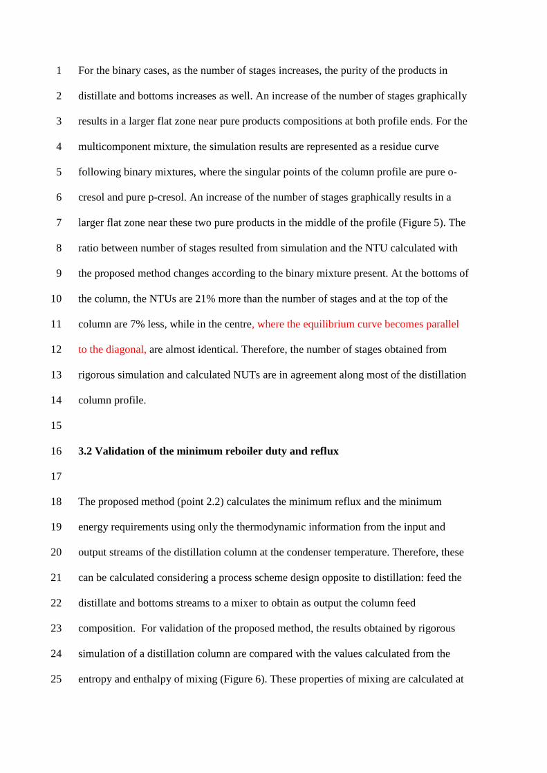
TRANSCRIPT
MINIMUM NUMBER OF TRANSFER UNITS AND REBOILER DUTY FOR 1
MULTICOMPONENT DISTILLATION COLUMNS 2
3
Valentin Pleşua, Alexandra Elena Bonet Ruiz
a*, Jordi Bonet
b, Joan Llorens
b, 4
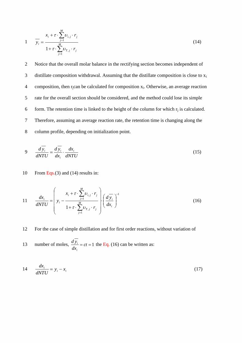
Petrica Iancua 5
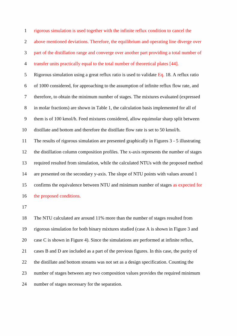
aUniversity POLITEHNICA of Bucharest, Centre for Technology Transfer in Process 6
Industries (CTTPI), 1, Gh. Polizu Street, Bldg A, Room A056, RO-011061 Bucharest, 7
Romania 8
bUniversity of Barcelona, Department of Chemical Engineering, 1, MartíiFranquès 9
Street, 6th
Floor, E-08028 Barcelona, Spain 10
11
Abstract 12
Some guidelines to evaluate distillation columns, considering only basic 13
thermodynamic data and principles, are provided in this paper. The method allows a 14
first insight to the problem by simple calculations, without requiring column variables 15
to ensure rational use of energy and low environmental impact. The separation system is 16
approached by two complementary ways: minimum and infinite reflux flow rate. The 17
minimum reflux provides the minimum energy requirements, and the infinite reflux 18
provides the feasibility conditions. The difficulty of separation can be expressed in 19
terms of number of transfer units (NTU). The applicability of the method is not 20
mathematically limited by the number of components in the mixture. Several mixtures 21
are rigorously simulated as illustrative examples, to verify the applicability of the 22
approach. The separation of the mixtures, performed by distillation columns, is feasible 23
if a minimum NTU can be calculated between the distillate and bottom compositions. 24
Once verified the feasibility of the separation, the maximum thermal efficiency depends 25
only on boiling point of bottom and distillate streams. The minimum energy 1
requirements corresponding to the reboiler can be calculated from the maximum 2
thermal efficiency, and the variation of entropy and enthalpy of mixing the distillate and 3
bottom streams. 4
5
Keywords: distillation column, thermal efficiency, minimum number of transfer units, 6
residue curve map, feasibility, minimum reboiler duty, infinite/infinite analysis. 7
8
*Corresponding author .Tel.: +4021-4023916; fax: +4021-3185900 9
E-mail address: [email protected] 10
11
Nomenclature 12
D distillate flowrate (kmol/h) 13
L reflux flowrate (kmol/h) 14
M number of chemical reactions 15
NC number of components in the system 16
Q overall thermodynamically calculated distillation column duty (kW) 17
Q’ distillation column duty required for mixture separation (kW) 18
Q” enthalpy of vaporization flow for the distillate stream (kW) 19
Qmin minimum distillation column duty, estimated by simulation (kW) 20
R ideal gas constant, 8.314 kJ/(kmol·K) 21
r reflux ratio (kmol/kmol distillate) 22
rj reaction rate of the reaction j (kmol/(kmol·h) 23
rmin minimum reflux ratio (kmol/kmol distillate) 24
S entropy (kJ/(kmol·K)) 25
T temperature (K) 1
TΔSsep entropic contribution to energy of mixing (kW) 2
xi mole fraction of component iin liquid phase 3
y vector of vapour mole fraction in direct contact with the liquid 4
yi mole fraction of component iin vapour phase 5
ΔHmixing enthalpic contribution to the energy of mixing (kW) 6
ΔSsep entropy of mixing/separation (kW/K) 7
8
Greek letters 9
dimensionless space coordinate 10
jT , net generation of moles from the reaction j 11
ji , stoichiometric coefficients for component i in chemical reaction j 12
η thermal efficiency of a Carnot cycle 13
Λ liquid hold-up in the rectifying section, m3 14
λ molar enthalpy of vaporisation (kJ/kmol) 15
τ retention time, h 16
17
Subscripts and superscripts 18
c condenser 19
dist distillate stream 20
feed feed stream 21
i component i 22
j chemical reaction j 23
min minimum 24
r reboiler 25

residue residue stream 1
2
Abbreviations 3
IA isoamylenes (2-methyl-1-butene + 2-methyl-2-butene) 4
MeOH methanol 5
MESH Mass Equilibrium Summation Enthalpy model 6
NTU number of transfer units 7
TAME tert-amyl-methyl- ether 8
9
1. Introduction 10
At early stages of process strategy for a new design, i.e. conceptual design step, it is 11
important to gather the required information to decide when it is worth to proceed to 12
further detailed studies, avoiding the possibility to obtain novel design with low 13
improvement potential. This first decision should be taken based on thermodynamic 14
data, before details about the process are available. This lack of data is compensated by 15
the fact that in early design stages, process operating parameters exact values are not 16
expected. Therefore, instead of fixing an arbitrary reflux to the column, it would be 17
preferable to fix it to infinite, or to its minimum value. Although it is not industrially 18
realistic, these assumptions provide the potential for the proposed process, and the 19
alternative processes to be compared easily, based on fast calculations. 20
One of the methods simplifying the distillation column model is the infinite/infinite 21
analysis. The Mass Equilibrium Summation Enthalpy (MESH) rigorous model used by 22
most of commercial process simulators usually has five degrees of freedom which 23
basically are covered by the following parameters: distillate flow rate, reflux ratio, 24
number of stages, feed stage and pressure, at a specified feed stream. Assuming an 25
infinite reflux flow rate, then the feed stream has no influence on the set of feasible 1
column profiles, only the pressure influences them. Once fixed the feed stream and the 2
distillate flow rate, the compositions of bottom and distillate streams are defined by 3
mass balance, that fulfils the condition of feasibility (existence of a column profile 4
between the distillate and bottoms compositions) and that the column profile contains a 5
singular point (pure component or azeotrope) according to the infinite/infinite 6
hypothesis [1]. The infinite/infinite analysis can provide easily interesting insights of 7
complicated processes that would be difficult to obtain by rigorous simulations, e.g. [2]. 8
The uncertainty between unfeasibility and mathematical convergence difficulties is 9
avoided. This analysis has been recently extended to study kinetically controlled 10
reactive distillation columns by Plesu et al [3], where the importance of energy savings 11
is underlined for any small improvement of the distillation process. The above 12
mentioned advantages of the infinite/infinite analysis allow tobe used and computer 13
implemented by important chemical companies [4]. 14
However, the assumption that some parameters are infinite, does not imply that all the 15
others must be also infinite, all the intensive variables, such as concentrations, degrees 16
of recovery, and temperatures, remain finite. In the same time, an infinite reflux flow 17
rate inside the distillation column, does not exclude finite input and output flow rates. 18
No output streams are obtained at total reflux (D=0), however these can be considered, 19
when the reflux flow rate is infinite (L → infinite). Similarly, an infinite reflux ratio can 20
be obtained when L → infinite, or D is zero (r=L/D), and the infinite/infinite analysis 21
assumes L infinite. At infinite reflux, a certain separation in two output compositions is 22
achieved by a minimum number of transfer units, who in turn can be infinite. The 23
infinite number of transfer units is generated by the presence of a singular point, and 24
their location is around this point, and not all along the column height. 25
Usually, the feasibility of a certain separation is checked by the so called residue curve 1
maps, which are assumed to represent graphically a set of composition column profiles 2
of a packed column, operated at infinite reflux flow rate [5]. The determination of the 3
number of transfer units (NTU) for these profiles provides a quantification of the 4
difficulty of the separation, which is not provided directly by the residue curves alone 5
[6, 7]. The agreement between residue curves and packed column profiles at infinite 6
reflux has been corroborated by some authors [8, 9] butfor reactive distillation it is not 7
always true [10]. 8
On the other hand, nowadays, the main drawback at the initial stage of process design is 9
the lack of a commonly used, non-iterative and fast method to estimate the energy 10
requirements of a distillation column [11], and usually these are determined later by 11
rigorous simulation (MESH model) [12]. A simultaneous approach is required to link 12
the models of the distillation columns with those of process heat exchange network 13
[13]. Estimation of distillation columns minimum energy requirements would be very 14
useful, as input for pinch analysis, which could provide an early value for the minimum 15
energy requirement of the global process. The environmental and economic aspects can 16
be assessed only after the energy requirements are determined. Energy efficiency 17
improvement for existing processes contributes to CO2 emissions reduction [14]. 18
Resource (energy) efficiency is a very important future trend in Process Systems 19
Engineering [15]. An exact cost value is very difficult to calculate, but a value 20
proportional to the cost can be provided for a distillation column, based on the 21
minimum number of transfer units (NUTmin) required and the minimum reboiler duty 22
[16]. 23
Hence, this paper focuses on the determination of minimum heat duty requirements of 24
an adiabatic distillation column, considering only thermodynamic data and principles, 25
as a basic method towards understanding and application to some more special schemes, 1
such as vapour recompression (e.g. [17], [18]), heterogeneous azeotropic distillation 2
[19], diabatic columns, divided wall column. Therefore, a divided wall column can be 3
modelled as combination of adiabatic distillation columns [20] or as a column globally 4
adiabatic [21] because the heat exchange takes place just internally. The lower energy 5
consumption of the divided wall columns can be related to higher second law efficiency 6
[22]. 7
8
9
2. Method development 10
11
2.1 Brief state of the art of methods to calculate distillation column parameters 12
13
The available methods to calculate distillation columns parameters are classified in 14
three main groups [24]: rigorous simulation models, stage by stage calculations and 15
analysis fixing parameters at limit conditions. The rigorous simulation models require 16
have as input data the reflux, number of stages (discrete variable) and feed plate among 17
the variables provided, e.g. MESH model [25] and the product purities are output data. 18
The resolution of these models requires a high computation effort as the model is made 19
of a large number of equations that are solved together until convergence is achieved. 20
Moreover, it is the key product purity that is usually known and not the column 21
parameters required by the model. 22
The second group, the stage by stage calculation models, deals with the sequential 23
resolution of the model as a consequence of using a product composition as input 24
parameter. This simpler resolution of the model is based on the fact that the data flow 25
can be inverted as long as the number of degrees of freedom of the distillation unit is the 1
same (Figure >>>>>>). The key-component composition in an output stream calculated 2
from the rigorous models is used now as input stream while the number of stages 3
becomes a calculated output. For binary mixtures, McCabe-Thiele method assumes 4
mass balances and constant molar overflow while Ponchon Savarit method takes into 5
account the energy balances e.g. [26]. The input data are the product key component 6
purity and an optimal feed plate condition that minimizes the required number of stages, 7
while the number of stages and optimal feed plate becomes output data. The reflux is 8
usually fixed according to a rule of thumb that calculates its optimum value starting 9
from its minimum value (in the interval of 1.2 to 1.5 times the minimum). The stage by 10
stage method can be extended to ternary mixtures, but in this case two degrees of 11
freedom are required to define the output stream, e.g. Boundary Value Method [27] 12
[28]. A further increase in the number of components cannot be easily handled due to 13
the limitation of the five degrees of freedom available in the distillation column. Three 14
degrees of freedom are fulfilled when specifying the pressure (affects thermodynamics), 15
reflux (direct influence on operation costs) and number of stages (direct influence on 16
capital costs), i.e. the reflux and number of stages are required to optimize the column. 17
These drawbacks appearing for multicomponent mixtures can be solved searching the 18
distillate composition that requires the shortest line from distillate to bottoms 19
composition becoming an optimization problem [29] [30]. This criteria of the shortest 20
line is an approximation of the lower number of stages criteria used by McCabe Thiele. 21
The above mentioned methods can be used to calculate the minimum reflux by 22
decreasing the reflux value until the number of stages becomes infinite. However, the 23
methods are simplifying from the beginning the model, assuming infinite number of 24
stages and require less computational effort to calculate the minimum reflux. 25
The third group of methods simplifies the model by fixing the number of transfer units 1
and/or reflux at boundary conditions, i.e. minimum or infinite values. Infinite reflux 2
means that for non-reactive packed column, its column composition profile matches a 3
section of a residue curve. Infinite NTUs means that the column composition profile 4
will reach a pinch point (non-evolution of the concentration). Infinite NTUs and infinite 5
reflux means that the pinch points reached are singular points. The Static Analysis [32] 6
assumes infinite reflux flow rate and minimum NTU. The Static Analysis is used to 7
provide a feasible value for distillate and bottoms streams compositions to be used in 8
the stage by stage calculation models, whose results are then employed as initialization 9
values of rigorous models [24]. The assumption of finite reflux and infinite NTU is used 10
by the pinch-based methods to calculate the minimum reflux under the Zero Volume 11
Criterion [32], Minimum Angle Criterion [33] or Eigenvalue Criterion [34]. All these 12
criteria suffer the drawback that the selection of the relevant pinch points can be rather 13
complicated, particularly for mixtures with more than three components. The 14
Rectification Body Method [34] [35] calculates all the pinch points for the rectifying 15
and stripping sections and defines a polyhedron body for each section where the pinches 16
are the vertex. The minimum reflux corresponds to the point where both bodies intersect 17
each other. When a column profile composition is known, this point can be used as 18
initial value for a stage by stage calculation model. This occurs in a distillation column 19
operated at minimum reflux characterized by a feed pinch. The feed pinch composition 20
can be calculated by the Rectification Body Method and then Feed Pinch Method [37] is 21
applied to perform the stage by stage calculation from feed pinch composition to both 22
column ends. The idea of using infinite NTU to calculate the minimum reflux was also 23
developed in the USSR literature [38]. The Feed Angle Method [39] is combining 24
elements of the above mentioned methods and an additional vertex is added to the 25
linearized rectification bodies to take into account the curvature providing very accurate 1
results for the minimum energy demand or reflux. Therefore, the nowadays available 2
methods to determine the minimum energy demand are based on a trial and error 3
method to find the minimum reflux that assures a feasible column profile from distillate 4
to bottoms composition under the infinite number of stages or transfer units assumption. 5
In a similar way as the infinite number of stages assumption at finite reflux, the 6
assumption of infinite reflux flow rate and infinite number of transfer units was 7
developed in USSR in 1971 [1], rediscovered in 1993 [40] achieving nowadays a high 8
grade of maturity [3]. 9
A new method in mid-way of the rigorous and shortcut models has recently been 10
proposed [31]. The mass/energy balance calculation for an overall distillation column as 11
well as certain key stages are incorporated into the short-cut model and solved 12
iteratively. It has solved successfully complex distillation systems. 13
In the present manuscript, an original non iterative method based on thermodynamic 14
efficiency is proposed. Composition profiles are determined for reactive packed 15
distillation columns operated at infinite reflux. The calculation of the minimum reflux 16
or energy demand of a distillation column is performed based on thermodynamic 17
efficiency, assuming a thermodynamic cycle. The number of stages and the reflux are 18
related by their minimum values [41] and therefore provides a base for more rigorous 19
computations. The aim of the proposed methodology is to provide additional fast and 20
easy to use tools for the conceptual design and not to substitute any of the existing 21
methods. It is recommended to explore an initial great number of alternatives, proceed 22
then with methods of increasing accuracy and then apply rigorous enough simulation 23
models. On the way, the alternatives with lower performance are disregarded and in the 24
end, the few most promising alternatives are subjected to a detailed evaluation. The 25
simplest existing methods to calculate the minimum number of stages and reflux are 1
useful for ideal mixtures, e.g. [42] [43], and the proposed method is able to solve any 2
multicomponent distillation process in a simplified way. 3
4
2.2 A method to estimate the minimum Number of Transfer Units (NTU) 5
6
Very often packed columns are modelled considering the concept of Number of 7
Transfer Units (NTU), according to a dimensionless expression [23]. The NTU 8
necessary for a given separation depends only on the composition column profile, and it 9
does not depend on the characteristics and performance of the packing. The NTU was 10
defined by [44] as: 11
2 2
1 1
y y
i iT
y y i i
d y d yNTU
y y y
(1) 12
where y is the vapour concentration in equilibrium with the liquid, and y is the vapour 13
concentration in direct contact with the liquid. The difference iiy y is the driving force 14
for the component i transfer from the liquid phase to the vapour phase. This expression 15
is used when the total number of transfer units along the overall height of the column is 16
fixed. Applying differentiation, it becomes: 17
i
i i
d ydNTU
y y
(2) 18
In this way, the dependence of the composition versus NTU is: 19
ii i
d yy y
dNTU
(3) 20
For a non-reactive distillation column, the mass balance on the rectifying section is: 21
D
i i iV y L x D x (4) 1
Where, V is the vapour molar flow rate, L is the liquid molar flow rate, and D is the 2
distillate flow rate. Assuming infinite reflux flow rate then L and V are infinite, whereas 3
D is a finite number and applying the l’Hôpital rule, 4
i iy x (5) 5
and, the NTU expression becomes, in the case of infinite reflux, the following equation: 6
i
i i
dxx y
dNTU
(6) 7
The similitude of this equation with the residue curve expression, without chemical 8
reaction, is obvious. The dimensionless time of the residue curve can be directly related 9
to the number of transfer units (NTU). 10
dNTUd (7) 11
The coincidence of the residue curve profile with the profile of a packed column 12
operating at infinite reflux, makes the residue curves useful to check the feasibility of 13
distillation systems, without chemical reaction. In this paper, the dimensionless time of 14
the residue curves has been equalised to NTU. This is one of the main contributions of 15
the present paper, as this fact has important implications. The agreement between 16
residue curves and packed column profiles at infinite reflux for non-reactive systems 17
has been corroborated by some authors [8, 9] but it was not previously identified in 18
literature that the dimensionless time of the residue curves matches the minimum NTU. 19
The residue curve maps are just used to check the feasibility of separation systems, but 20
as it is related to the NTU, it means that it is also possible to quantify how difficult is 21
the separation. 22
1
i i i
dNTU
dx x y
(8) 1
The value of NTU necessary to change the concentration of a component between 0
ix2
and xi is: 3
,0
xi
i
i ixi
dxNTU
x y
(9) 4
5
A similar equation for NTU dependence of composition can be also determined for 6
reactive systems. The molar balance for the rectifying section of a reactive distillation 7
column is: 8
,
1
MD
i i i i j j
j
V y D x L x r
(10) 9
where, Λ is the liquid hold-up in the rectifying section and rj is the reaction rate in 10
rectifying section. The overall molar balance is: 11
,
1
M
T j j
j
V D L r
where, ,
1
N
T j i j
i
ν ν
(11) 12
From the last two equations: 13
, ,
1 1
M MD
T j j i i i i j j
j j
D L r y D x L x r
(12) 14
From these equations, one obtains: 15
,
1
,
1
1
MD
i i i j j
j
i M
T j j
j
Dx x r
L Ly
Dr
L L
(13) 16
As L is infinite and D is a finite number, then D/L→ 0 and Λ/L corresponds to the 17
residence time (τ) on the column section: 18
M
j
jjT
M
j
jjii
i
r
rx
y
1
,
1
,
1
(14) 1
Notice that the overall molar balance in the rectifying section becomes independent of 2
distillate composition withdrawal. Assuming that the distillate composition is close to xi 3
composition, then rjcan be calculated for composition xi. Otherwise, an average reaction 4
rate for the overall section should be considered, and the method could lose its simple 5
form. The retention time is linked to the height of the column for which rj is calculated. 6
Therefore, assuming an average reaction rate, the retention time is changing along the 7
column profile, depending on initialization point. 8
dNTU
dx
dx
yd
dNTU
yd i
i
ii (15) 9
From Eqs.(3) and (14) results in: 10
1
1
,
1
,
1
i
i
M
j
jjT
M
j
jjii
i
i
dx
yd
r
rx
ydNTU
dx
(16) 11
For the case of simple distillation and for first order reactions, without variation of 12
number of moles, 1 ctdx
yd
i
i the Eq. (16) can be written as: 13
ii
i xydNTU
dx (17) 14
For systems of reactive distillation, the expression i
i
d yct
dx and is more complex. The 1
present study is focused on the simplified case when 1i
i
d yct
dx . In this case, Eq. (16) 2
becomes: 3
M
j
jjT
M
j
jjii
i
i
r
rx
ydNTU
dx
1
,
1
,
1
(18) 4
5
Therefore, in this paper, some new points of view related to residue curve maps are 6
introduced, such as the use of integration results in a NTU map, in addition to the 7
differential results in a residue curve map. This provides additional information about 8
the difficulty of the separation. 9
10
2.3 A method to determine the minimum reboiler duty and reflux 11
12
For a distillation column, a first approach to determine the minimum energy 13
consumption is assuming it proportional to the distillate flow rate [45], without taking 14
into account the reflux. This is in agreement with heuristic, that a direct separation 15
sequence is preferable to other topologies. 16
The product recovered by the bottom stream of the distillation column has been heated, 17
but the entire product collected by the distillate stream has been previously evaporated, 18
consuming more energy. The extractive agents used to enhance some distillation 19
processes usually have high flowrates, their boiling point is relatively high and they are 20
not evaporated, being recovered by the bottom stream. The refluxed flowrate which 21
represents a material stream making a closed cycle inside the column is not taken into 1
account (Figure 1). 2
The heat distribution taking place in the distillation column is schematically represented 3
in Figure 1. On one side there is the closed thermodynamic cycle in which the 4
separation takes place (black area). On the other side there is the energy required to 5
collect the distillate flowrate at the top of the column (grey area). According to this 6
distribution, the overall reboiler duty is calculated as a sum between the energy required 7
to perform the separation and the energy required to produce the distillate stream. The 8
thermodynamic cycle as represented is a simplification which allows us to estimate the 9
energy consumption induced by the reflux rate. In a real distillation column, there is the 10
mixing between liquid and vapour streams. The mixing between the descending liquid 11
and the ascending vapour generates irreversibility, which cannot be avoided, no matter 12
the number of stages or transfer units employed. Although the distillation column can 13
be considered having a great number of stages or transfer units, the change of 14
composition takes places only in a few stages and most of the column profile presents 15
wide sections where the compositions do not change. In order to avoid column profiles 16
calculations, as a first approximation, a reversible cycle can be assumed with no internal 17
mixing, where the feed stream does not produce a change of entropy in the feed plate. 18
The ideal (Carnot) efficiency is widely used for heat engines, e.g. [46], but it has never 19
been applied before to a distillation column, even though Carnot [47] already claimed 20
that any system consuming heat at a certain temperature and delivering it at a lower 21
temperature can be studied as a thermal cycle. In literature, the thermodynamic aspects 22
of distillation columns are studied from exergy point of view, e.g. [48], which provides 23
a performance value thatcannot be related to the reflux and does not provide any 24
information about the minimum heat requirements of the column. In a similar way, as in 25
the case of a thermal engine, the minimum heat consumption can be determined in 1
relation with the hot and cold temperatures to produce a certain work, for a distillation 2
column the minimum heat consumption can be calculated to achieve a certain 3
separation. In this section, the thermal cycle for a distillation column is presented, and 4
the minimum heat calculated. 5
For this purpose, a delimited number of moles circulating inside a distillation column is 6
considered to perform a thermodynamic cycle, as shown in the T-S diagram (Figure 2). 7
Due to the mass transfer, the composition of the delimited number of moles is changing 8
while ascending or descending along the column. This change of composition by itself 9
does not affect the performance of the cycle because the performance is independent of 10
the working fluid composition. A reversible process is assumed; therefore the heat is 11
provided at a small finite temperature difference above the reboiler temperature (Tr) and 12
eliminated at a small finite temperature difference below the condenser temperature 13
(Tc). There is an isothermal phase change in the reboiler and condenser (liquid/vapour) 14
(segments 1-2 and 3-4-5-6). The vapour decreases its temperature while ascending 15
(segment 2-3) by exchanging heat with the descending liquid (segment 6-1) whose 16
temperature increases. At any point inside the distillation column, the liquid and vapour 17
in contact are in equilibrium and therefore have the same temperature. Assuming that 18
the column is adiabatic, the heat eliminated by the ascending vapour must be equal to 19
the heat received by the descending liquid. Therefore, at any column height, the sum of 20
the entropy of the liquid and the vapour must be constant along the column. The change 21
of certain amount of entropy in the liquid is compensated by the same amount of 22
entropy in the vapour. According to this, the grey area under the segment 6-1 (area 6-1-23
5-8-7-6) should be equal to the grey area under the segment 2-3 (area 2-3-10-9-4-2). In 24
the same time, the process reversibility should be assured. The input and output streams 25
should be at the same specific entropy that the point to or from they are feed or 1
extracted. Hence, the optimal feed stage is the stage with the same specific entropy, as 2
the feed stream. 3
The overall heat provided to the cycle would be the area under 6-1-2-3 (area 6-1-2-3-10-4
9-8-7-6), but as there is a heat exchange between both grey areas (6-1 and 2-3), then the 5
heat duty provided is the area under the isotherm 1-2 (area 1-2-4-9-8-5-1). The overall 6
heat to be removed from the cycle is the area under the isotherm 3-6 (area 3-4-5-6-7-8-7
9-10) which should be considered entirely, as there is no regeneration section as for the 8
heat duty. The result is that the area under the isotherm 1-2 (area 1-2-4-9-8-5-1) is equal 9
to the area under the isotherm 3-6 (area 3-4-5-6-7-8-9-10), this implies that the heat 10
provided to the cycle is equal to the heat eliminated from the cycle. Hence, a distillation 11
column has not a net consume of energy, but it creates a decrease of energy quality. The 12
same heat provided to the reboiler is collected in the condenser, but at a lower 13
temperature (usually there is a small difference between these values, equal to the 14
enthalpy variation between input and output streams). Therefore: 15
QQQ cr (19) 16
According to the heat distribution illustrated in Figure 1, the distillation column heat 17
duty can be divided into the duty required to produce the distillate stream, and the duty 18
required to perform the separation. 19
ccrr QQQQ (20) 20
The heat eliminated to produce the distillate (Q”c) requires that the same amount that it 21
was provided to the reboiler (Q”r). 22
DQQQ cr (21) 23
As it is the same amount, the energy required by the vapour, which is collected as 1
distillate, to reach the top of the column is not considered in the following relations, 2
which take into account only the energy of separation. 3
QQQ cr (22) 4
65435412 SSTSSTSSTSST cccr (23) 5
As 5412 SSSS and 6543 SSSS 6
12
652SST
SS
TT
TT
rcr
cr
(24) 7
As rr QSST 12 , then: 8
r
cr
r
cT
TT
Q
SST
652 (25) 9
The thermal efficiency of Carnot cycle is: 10
r
cr
T
TT (26) 11
rc QSST 652 (27) 12
The distillation column uses the provided heat with the same thermal efficiency defined 13
by a thermal engine. However, instead of using it to produce work, the distillation 14
column uses it to produce a change of entropy, in other words, to produce the 15
separation. The degradation of thermal energy between reboiler and condenser makes 16
possible to lower the entropy of the material, which is the separation of a liquid mixture 17
[49].Then the term 652 SSTc should be equal to the difference of entropy 18
between the output streams and the input streams feed to the column at constant 19
temperature Tc. Therefore, the minimum heat required for a certain separation depends 20
on the increment of entropy of mixing the product streams to obtain the original feed 21
streams (change of entropy required by the separation) divided by the thermal efficiency 1
of Carnot. 2
sepc
r
STQ
(28) 3
For liquid ideal solutions, where the enthalpy of mixing is close to zero, the excess 4
entropy is negligible. The entropy of mixing of ideal liquids can be approximated to the 5
mixing entropy of gases [50], according to the following equation: 6
ln ln lnfeed feed distil distil residue residue
sep i i i i i iS R D B x x D x x B x x (29) 7
Notice that Q’r represents only the energy to perform the separation. Therefore, the heat 8
required by the distillate to reach the top of the column should be added to obtain the 9
overall minimum reboiler requirements. When two streams of different compositions 10
are mixed, there is entropy of mixing, but sometimes the enthalpy of mixing can be 11
significant enough to be taken into consideration. Therefore the energy provided to the 12
column corresponds to the reboiler duty, adding the enthalpy of mixing as a factor of 13
correction. 14
DST
HQsepc
mixingr
(30) 15
The reboiler duty of a distillation column should be higher than the previously 16
calculated value, due to the irreversibility produced when mixing the column internal 17
flows, and also when mixing the feed streams with the internal flows. The irreversibility 18
produced by the feed streams is obvious in multicomponent systems by the deviation of 19
the column profile around this point. 20
Another assumption in addition to the reversibility of the process is to consider a 21
constant molar overflow along the column. According to this, an estimate of the 22
minimum reflux ratio can be calculated as follows: 23
mixingHD
Lr
(31) 1
where 2
sepc STL
(32) 3
therefore: 4
mixing
sepc
HD
STr
(33) 5
6
In this case, the reflux represents the ratio between the energy to perform the separation 7
including the efficiency of Carnot and the energy required to collect the distillate stream 8
at the top of the column. 9
10
3. Validation of the method by rigorous simulation 11
12
3.1 Validation of the minimum Number of Transfer Units 13
14
There are no real stages or integral steps in a packed distillation column, and therefore 15
the NTU are different from the number of theoretical stages proposed by Daniels and 16
Alberty (1975) [51] and calculated discrete liquid vapour equilibrium changes at each 17
stage (it is not a continuous variation). These are only equal when the equilibrium curve 18
is parallel to the operation line, a condition rarely occurring. If the driving force values 19
increase (yi-xi in Eq. 3), fewer transfer units than theoretical plates are required; if 20
values of driving force decrease, the reverse is true. Therefore, a condition of equimolar 21
flow rate distribution between distillate and bottom is considered in the illustrative 22
examples used to check the NTU. The number of theoretical stages provided by 23
rigorous simulation is used together with the infinite reflux condition to cancel the 1
above mentioned deviations. Therefore, the equilibrium and operating line diverge over 2
part of the distillation range and converge over another part providing a total number of 3
transfer units practically equal to the total number of theoretical plates [44]. 4
Rigorous simulation using a great reflux ratio is used to validate Eq. 18. A reflux ratio 5
of 1000 considered, for approaching to the assumption of infinite reflux flow rate, and 6
therefore, to obtain the minimum number of stages. The mixtures evaluated (expressed 7
in molar fractions) are shown in Table 1, the calculation basis implemented for all of 8
them is of 100 kmol/h. Feed mixtures considered, allow equimolar sharp split between 9
distillate and bottom and therefore the distillate flow rate is set to 50 kmol/h. 10
The results of rigorous simulation are presented graphically in Figures 3 - 5 illustrating 11
the distillation column composition profiles. The x-axis represents the number of stages 12
required resulted from simulation, while the calculated NTUs with the proposed method 13
are presented on the secondary y-axis. The slope of NTU points with values around 1 14
confirms the equivalence between NTU and minimum number of stages as expected for 15
the proposed conditions. 16
17
The NTU calculated are around 11% more than the number of stages resulted from 18
rigorous simulation for both binary mixtures studied (case A is shown in Figure 3 and 19
case C is shown in Figure 4). Since the simulations are performed at infinite reflux, 20
cases B and D are included as a part of the previous figures. In this case, the purity of 21
the distillate and bottom streams was not set as a design specification. Counting the 22
number of stages between any two composition values provides the required minimum 23
number of stages necessary for the separation. 24
For the binary cases, as the number of stages increases, the purity of the products in 1
distillate and bottoms increases as well. An increase of the number of stages graphically 2
results in a larger flat zone near pure products compositions at both profile ends. For the 3
multicomponent mixture, the simulation results are represented as a residue curve 4
following binary mixtures, where the singular points of the column profile are pure o-5
cresol and pure p-cresol. An increase of the number of stages graphically results in a 6
larger flat zone near these two pure products in the middle of the profile (Figure 5). The 7
ratio between number of stages resulted from simulation and the NTU calculated with 8
the proposed method changes according to the binary mixture present. At the bottoms of 9
the column, the NTUs are 21% more than the number of stages and at the top of the 10
column are 7% less, while in the centre, where the equilibrium curve becomes parallel 11
to the diagonal, are almost identical. Therefore, the number of stages obtained from 12
rigorous simulation and calculated NUTs are in agreement along most of the distillation 13
column profile. 14
15
3.2 Validation of the minimum reboiler duty and reflux 16
17
The proposed method (point 2.2) calculates the minimum reflux and the minimum 18
energy requirements using only the thermodynamic information from the input and 19
output streams of the distillation column at the condenser temperature. Therefore, these 20
can be calculated considering a process scheme design opposite to distillation: feed the 21
distillate and bottoms streams to a mixer to obtain as output the column feed 22
composition. For validation of the proposed method, the results obtained by rigorous 23
simulation of a distillation column are compared with the values calculated from the 24
entropy and enthalpy of mixing (Figure 6). These properties of mixing are calculated at 25
a constant temperature corresponding to the condenser temperature. The enthalpy of 1
mixing is calculated according to the cooling required to bring the resulting mixed 2
stream back to condenser temperature. 3
The mass and energy balances inside the column, taking into account the irreversibility, 4
are calculated by distillation column rigorous simulation with AspenPlus®, considering 5
UNIFAC thermodynamic model. The ascending vapour is mixed with the descending 6
liquid and the entrance of feed streams produces irreversibility. To validate the data 7
collected by the simple mixer, a rigorous simulation of a distillation column at 1 bar 8
with a big number of stages (200 stages) with the feed stage in the middle is used. A 9
design specification changes the reflux ratio at the total condenser, for getting the 10
desired purity in the output streams. As the number of stages is big enough, the reflux 11
and reboiler duty should be close to their minimum values. The mixtures evaluated 12
(expressed in molar fractions) and design specifications are shown in Table 1, the 13
calculation basis implemented for all of them is of 100 kmol/h. Feed mixtures 14
considered, allow equimolar sharp split between distillate and bottom, and therefore the 15
distillate flow rate is set to 50 kmol/h. 16
The specific entropy for the input and output streams in the mixing process (Figure 6b) 17
and the heat duty to the cooler for each case (enthalpy of mixing) are presented in Table 18
2. The boiling points of the distillate and residue streams correspond to the temperatures 19
in the reboiler and in the column condenser, being presented in Table 3, together with 20
minimum reboiler duty and minimum reflux, estimated by rigorous simulation. The 21
column efficiency can be calculated using the condenser and reboiler temperatures in 22
the same way as for a thermal engine (Eq. 26); the results are presented in Table 4. The 23
energy loss due to mixing the streams (Figure 6b) is calculated between input and 24
output streams, as product of the specific entropy and flow rates for each stream 25
multiplied by the condenser temperature (see column T·ΔSsep in Table 4). The 1
reboilerduty required to separate again the mixture (Q’) is calculated according to (Eq. 2
28). Moreover, an additional reboiler duty Q’’ related to the distillate should be taken 3
into account (Eq. 20), according to the scheme in Figure 1, allowing to obtain the 4
overall reboiler duty Q (Table 4). The results of the minimum reboiler duty and 5
minimum reflux estimated by rigorous simulation are compared to their equivalent 6
values calculated by the proposed method (Table 5). The discussion of the results is 7
provided in the following paragraphs. 8
9
In the first case (A), a binary mixture of methanol and ethanol is evaluated (case A 10
Table 1). This is discussed in more detail, according to the proposed method. A stream 11
with 95% methanol and 5% ethanol at 1 bar, at its boiling point is mixed with another 12
stream containing 5% methanol and 95% ethanol at 1 bar and same temperature. Both 13
streams have same flowrate i.e. 50 kmol/h, (Figure 6b). In this way, both streams are at 14
the same temperature as the column distillate temperature (Tc = 337.8 K) (Figure 6a). 15
Due to the enthalpy of mixing, the temperature of the mixed stream increases slightly 16
(T=343.1 K). Therefore the heat exchanger B3 is used to cool this stream back to the 17
temperature of the feed streams. The heat consumed by this cooler corresponds to the 18
enthalpy of mixing (ΔHmixing = 4.57 kW). 19
Once mixed, a higher amount of energy is required to separate it again. This energy 20
must come from a distillation column that can be considered as a thermal machine 21
working between a hot and cold source, the reboiler being the hot source and the 22
condenser the cold source. As demonstrated previously, efficiency of Carnot is also 23
applicable to the distillation columns and therefore the required heat for the separation 24
(Q’ = -942.32 kW) represents the energy due to the entropy of mixing (TΔSsep = -33.52 25
kW) divided by the efficiency of the Carnot cycle (η = 0.0356) (Eq. 28). The entropy of 1
mixing and the efficiency are calculated as follows. 2
The entropy of each stream is calculated as product of its flow rate and specific entropy 3
(Table 2). The difference of entropy between the input and the output streams at 4
temperature Tc provides the entropy of mixing (-355.3 kJ·h-1
·K-1
). The product between 5
the entropy of mixing and the temperature Tcprovides the energy loss by the entropy 6
generated: 33.52 kW (Table 4). The temperature in the reboiler (Tr) is 350.26 K which 7
represents the boiling point of 95% ethanol stream. The temperature in the condenser 8
(Tc) is of 337.8 K (Table 3), representing the boiling point of 95% methanol stream. 9
Therefore, the efficiency calculated from the previous temperature values (Eq. 26) is of 10
3.56% (Table 4). 11
The reboiler duty (Q = -1,435.15 kW) is the sum of the energy required by the distillate 12
stream (Q’’= -492.83 kW) and the energy required to separate the mixture (Q’ = -13
942.32 kW) (Table 4). The enthalpy of mixing is added to the minimum reboiler duty 14
simulated (Qmin), but in this case its influence is negligible. By rigorous simulation of a 15
distillation column, the condenser duty resulted is of 1,640.40 kW, only 14% higher 16
than the one calculated thermodynamically. Using these results and the Eq.(33) to 17
determine the reflux, a calculated reflux of 1.9 is obtained versus a value of 2.3 18
estimated by rigorous simulation (Table 5). Therefore, the values thermodynamically 19
calculated are in very good agreement with the values estimated by rigorous simulation. 20
21
In case B, the same separation is considered as in case A (methanol and ethanol), but 22
they are separated to a higher purity of 99% (Table 1). The efficiency obtained is similar 23
to that obtained for case A (3.85%), but the enthalpy of mixing is not any more 24
negligible (-495.24 kW) (Table 2). The minimum thermodynamic reboiler duty is 25
greater than in case A, as expected (Q = -1,594.08 kW), but the simulated condenser 1
duty (Qmin = -1,779.50 kW) is 61.9% higher than the one thermodynamically calculated 2
(Table 4). When the enthalpy of mixing is added to the simulated minimum reboiler 3
duty, the difference between them is about 43%. These results show that when the 4
enthalpy of mixing is not negligible, the irreversibility inside the column is higher. 5
6
In case C separation of binary mixture benzene and toluene is considered to obtain 7
purity of 95% (Table 1). The enthalpic and entropic contribution to the mixing is similar 8
to the previous B case (Table 2 and 4), e.g. ΔSsep (C: 455.62 kJ·h-1
·K-1
and B:451.44 9
kJ·h-1
·K-1
) are almost the same. The higher difference between the condenser and 10
reboiler temperature (for case C: 353.8 – 381.1 K and for case B: 337.4-351.0 K) 11
produces a higher efficiency (7.15%) and the resulting Q’ required for the separation 12
becomes considerable smaller (-622.78 kW) (Table 4). When Q’ is compared to the 13
condenser duty value obtained by rigorous simulation of the distillation column (Qmin = 14
-932.17 kW), the difference is of 48.6%. When the enthalpy of mixing is taken into 15
account this difference becomes 29%. Also the reflux for case C is smaller than for case 16
B. The thermodynamically calculated reflux is of 1.08 and the estimated reflux value 17
obtained by rigorous simulation is of 1.16, which is in good agreement. Therefore, 18
higher is the difference between the distillate and bottoms temperatures, the process is 19
more efficient and a lower reflux is required. 20
21
In case D same binary system as in case C is considered, but at a higher purity of 99% 22
for the output streams (Table 1) is imposed. The enthalpy of mixing and energy required 23
for the distillate stream are almost similar to case C. But as the purities are higher, the 24
temperatures of distillate and bottom streams differ more, while the efficiency also 25
increases (7.8%). Nevertheless, the entropic contribution to the energy of mixing 1
increases at a higher extent resulting in a higher thermodynamic condenser duty (Q’) of 2
-726.35 kW (Table 4), although the efficiency is higher. The condenser duty estimated 3
by simulation is of -242.75 kW, the difference to the one calculated thermodynamically 4
being around 38.7% (Table 3). When corrected using the enthalpy of mixing, the 5
difference is of 25%. The calculated reflux is of 1.19 and the value estimated by 6
rigorous simulation is of 1.37, with only 15% of difference. Therefore, the higher 7
condenser duty and the reflux required to obtain a higher purity is mainly consequence 8
of the higher entropy of mixing. Notice that the minimum condenser duty to separate a 9
binary mixture in pure components is a finite value, and it can be used to calculate the 10
energy requirements of a process under the infinite/infinite assumption. 11
12
Once verified the obtained results with the estimated values by rigorous simulations for 13
binary mixtures, in case E (Table 1) the results obtained for an equimolar 14
multicomponent mixture of 100 kmol/h composed of phenol, o-cresol, m-cresol and 15
3,5-xylenol are presented. Phenol and o-cresol are separated in distillate stream with an 16
overall purity of 95% whereas m-cresol and 3,5-xylenol are separated in bottoms 17
stream, using a distillate flow rate of 50 kmol/h. The enthalpy of vaporization for the 18
distillate stream (Q’’) is -655.70 kW, the enthalpy of mixing is -2.63 kW and the energy 19
required for separation (Q’) is of -1,071.75 kW (efficiency of 5.14%) resulting in 20
condenser duty of -1,727.45 kW. The difference between calculated value and the value 21
resulted from rigorous simulation for the condenser duty (-2,599.91 kW) is of 51%. 22
This difference is quite high compared to the equivalent case A, with a negligible heat 23
of mixing. The irreversibility is caused by the perturbation produced by the feed stream. 24
This is illustrated by column composition profile. The feed position can be easily 25
identified in Figure 7 due to the deviations and break of the composition column 1
profiles near the feed point. 2
3
In case F, similar multicomponent separation problem to case E is proposed, but the 4
purity of product streams is imposed to 99% (Table 1). The entropic contribution to the 5
energy of mixing in this case increases, as expected, to a higher value (-67.40 kW), but 6
the main difference is that the enthalpy of mixing is not any more negligible (-656.27 7
kW). The calculated condenser duty (Q) is -1,907.66 kW and the estimated one by 8
rigorous simulation (Qmin) is -2,942.79 kW which becomes -3,599.40 kW (Table 5) 9
when taking into account the enthalpy of mixing. In this case, the difference is 89% 10
compared to the thermodynamically calculated one. The reason for the higher 11
discrepancy for multicomponent mixtures can be explained by the composition profiles 12
which present a remarkable break of the tendency for some of the components at the 13
feed plate. This leads to a high degree of irreversibility. Furthermore, the irreversibility 14
produced by the enthalpy of mixing is sharpened by the irreversibility produced at the 15
feed plate. A continuous computation of the packed columns would provide values 16
closer to the calculated ones, assuming a reversible separation instead of the rigorous 17
model implemented in the simulator which takes into account discrete stages. 18
19
4. TAME synthesis as illustrative example for the proposed method 20
21
The previously presented problems are easily studied directly by rigorous simulation, 22
but there are more complex processes not so easy to analyse. For instance, the synthesis 23
of TAME (tert-amyl-methyl-ether), an important gasoline additive, can be performed 24
using the technology of catalytic distillation (from methanol and isoamylenes) in a 25
hybrid reactive distillation column with the non-reactive section in the bottom. The 1
feasibility and the influence of several design parameters on the number of stages and 2
energy consumption of such a complex process is not an easy task to be analysedby 3
rigorous simulation. The convergence of the simulation environment requires a long 4
time of trials and the difficulty to reach a converged flowsheet is not always a sign of 5
non-feasibility of the configuration considered. To determine all the feasible 6
combinations of parameters influencing the system analysedis not always straight-7
forward. Therefore, the proposed method simplifies the model at the extreme conditions 8
to avoid the convergence problems and provide a fast insight of the problem behaviour. 9
This behaviouris reflected in two kinds of complementary maps: a map illustrating 10
feasibility and minimum number of stages and a map showing the distillation column 11
thermal efficiency. The first map is based on the assumption of infinite reflux flow rate 12
and the difficulty of the separation is reflected in the NTUs required according to the 13
Eq.(18). The second map is based on the thermal efficiency that defines the minimum 14
energy requirements of the distillation column and the minimum reflux. The thermal 15
efficiency of the distillation column depends only on the temperatures of distillate and 16
bottom streams. The aspect of both graphics is similar to a topographic map. The main 17
coincidence between them is that the maximum and minimum temperatures coincide 18
also with singular points (pure components or azeotropes) at which the difficulty of 19
separation is maximum as well. As differences, the temperature map topology does not 20
depend on the retention time inside the reactive distillation column, while the NTUs 21
map topology strongly depends on the retention time. Pressure influences both types of 22
map topology, but at different extent. These maps are discussed for this illustrative 23
example in more detail in the following paragraphs. 24
Figure 8 illustrates the maps at 4 bar. The NUTs map is composed of a set of curves 1
obtained when applying Eq.(18). Any feasible separation composition can be placed on 2
a common residue curve and the section of curve between them corresponds to the 3
distillation column composition profiles assuming a packed column operated at infinite 4
reflux flow rate. The minimum NTUs for the required separation are mathematically 5
obtained integrating Eq.(18). Graphically, the minimum NTUs can be directly obtained 6
when counting the number of circles in the section of curve corresponding to the 7
column profile. The NUTs map for TAME synthesis is divided in two distillation 8
regions with a common unstable node (isoamylenes/methanol azeotrope). Most of the 9
feasible column profiles depart from this azeotrope and converge to pure TAME vertex, 10
while some other column profiles converge to pure methanol. The optimum profile 11
corresponds to minimum NTUs required for a separation, fulfilling certain restrictions 12
to bottoms and distillate compositions. It is obtained when the profile crosses regions 13
where the separation is fastest (maximum difference between the yiterm and the rest in 14
Eq. 18) and the way is shortest (the overall NTUs resulted from integration). 15
Comparing both maps (Figure 8), the maximum temperatures correspond to stable 16
nodes, e.g. pure TAME, and the minimum temperature corresponds to the unstable 17
node, i.e. methanol/isoamyleneazeotrope. The column efficiency can be determined 18
easily from Eq.(26) as it only depends on temperature. Therefore, when the distillation 19
column is operated in the distillation region corresponding to methanol stable node, the 20
NTUs are small but the thermal efficiency is low. On the other hand, the operation in 21
the distillation region corresponding to TAME stable node requires more NTUs, but the 22
thermal efficiency is higher. The presence of the reaction term does not change the 23
column efficiency as the boiling points at each composition are the same. The enthalpy 24
of the reaction must be taken into account when the minimum reboiler duty is 25
calculated. However, the presence of reaction influences the topology of the NTUs map, 1
changing the position of the nodes and saddles and affecting the difficulty of separation 2
(Figure 9). 3
The temperatures map and the representation of NTUs on residue curve maps provide 4
an useful tool and a valuable additional information to propose more energy efficient 5
process schemes and designs. 6
7
5. Summary of the proposed method 8
9
The feasibility of a distillation process requires the fulfilment of the mass balances and 10
the existence of a column profile between the distillate and bottoms composition. The 11
existence of the column profile can be checked at infinite reflux using the following 12
expression (Eq. 16) for packed columns: 13
1
1
,
1
,
1
i
i
M
j
jjT
M
j
jjii
i
i
dx
yd
r
rx
ydNTU
dx
(16) 14
This expression is implemented in most of the commercial simulators but only for non-15
reactive mixtures and does not indicate the NTU. The NTU is an important parameter as 16
provides an insight of the capital costs associated to the separation. In a more 17
approximated manner, the capital costs associated can be considered related to the 18
residue curve or profile length. Eq. (16) is a general expression taking into account the 19
reaction kinetics, but it can be simplified for non-reactive systems to Eq. (6): 20
i
i i
dxx y
dNTU
(6) 21

The last expressions are the basis for the infinite reflux assumption analysis models, e.g. 1
infinite/infinite analysis, and therefore the output streams compositions and flow rate 2
can be determined. A separation is feasible only if the reflux is higher than its minimum 3
value, therefore the minimum reflux is valuable information that in turn is related to the 4
operational costs. The optimum reflux is usually calculated with rules of thumb that 5
relates it with its minimum value. The present paper presents an original way to 6
calculate it from thermodynamic assumptions (Eq. 33): 7
mixing
sepc
HD
STr
(33) 8
where 9
r
cr
T
TT
(26) 10
ln ln lnfeed feed distil distil residue residue
sep i i i i i iS R D B x x D x x B x x (29) 11
The results of this method (minimum NTU and reflux) can be used as initialization 12
values for iterative more rigorous methods. 13
6. Conclusions 14
This paper proposes a new expression to model the compositions profile of a packed 15
distillation column operated at infinite reflux flow rate. The results can be used to 16
determine the minimum Number of Transfer Units for a given separation. NUT is useful 17
to evaluate de difficulty of the separation, complementing the information from residue 18
curve maps for the feasibility of the separation. An original treatment is proposed to 19
evaluate feasibility/difficulty of separation for reactive distillation. On the other hand, it 20
is proposed an original method to calculate the minimum reboiler duty, based on the 21
thermodynamic efficiency of a distillation column, and the change of entropy between 22
the input and output streams. Higher the difference between the distillate and bottoms 23
compositions, more efficient is the distillation column. The separation leading to 24
streams of higher purity is associated to a higher efficiency. The entropic contribution to 1
the energy of mixing, increases the energy requirements at a higher extent than the 2
savings due to the increase of efficiency producing higher reboiler duty requirements. 3
The minimum reboiler duty to separate a binary mixture in pure components is a finite 4
value, but the number of transfer units to separate in pure components is considered 5
infinite. Therefore the method can be applied in combination with the infinite/infinite 6
analysis. 7
When the heat of mixing is negligible, the results are in very good agreement with the 8
values estimated by rigorous simulation. Otherwise, a higher difference is observed 9
between the minimum reboiler duty thermodynamically estimated, and the one 10
calculated by rigorous simulation. This is caused by irreversibility produced due to 11
mixing inside the distillation column between liquid and vapour flowing in opposite 12
directions. The irreversibility is sharpened in multicomponent mixtures due to the feed 13
stream that produces a clear perturbation of the composition profiles for several 14
compounds. Due to the irreversibility, the estimated minimum reboiler duty by rigorous 15
simulation can be several times bigger than the minimum thermodynamically calculated 16
value. 17
18
Acknowledgements The authors would like to thank the financial support of POSCCE 19
project ID 652 (Structural Funds for Development and Cohesion) and the project 20
CTQ2009-11465 (Ministry of Science and Innovation – Spanish Government) who 21
provided the opportunity to complete this research. 22
23
References 24
[1] F.B. Petlyuk, V.S. Avetyan, Investigation of the rectification of three-component 1
mixtures with infinite reflux, Theor.Found.Chem.Eng. 5(1971) 499–507. 2
3
[2] J. Bonet, R. Thery, X.-M. Meyer, M. Meyer, J.-M.Reneaume, M.-I. Galan, J. Costa, 4
Infinite/Infinite Analysis as a Tool for an Early Oriented Synthesis of a Reactive 5
Pressure Swing Process, Computers & Chemical Engineering 31(5-6) (2007) 487-495. 6
7
[3] A.E. Pleşu, J. Bonet, V. Pleşu, G. Bozga, M.-I.Galan, Residue Curves Map Analysis 8
for Tert-Amyl Methyl Ether Synthesis by Reactive Distillation in Kinetically Controlled 9
Conditions with Energy-Saving Evaluation, Energy 33 (10) (2008) 1572-1589. 10
11
[4] O. Ryll, S. Blagov, H. Hasse, ∞/∞-Analysis of Homogeneous Distillation Processes, 12
Chemical Engineering Science 84 (2012) 315–332. 13
14
[5] A.E. Bonet-Ruiz, J. Bonet Ruiz, V. Pleşu, G. Bozga, J. LlorensLlacuna, J. Costa 15
Lopez, New Contributions to Modelling and Simulation of TAME Synthesis by 16
Catalytic Distillation, Chemical Engineering Transactions 18 (2009) 959-964. 17
18
[6] A.E. Bonet-Ruiz, J. Bonet, G. Bozga, J. LlorensLlacuna, V. Pleşu, Number of 19
Transfer Units Information on Residue Curve Maps, Chemical Engineering 20
Transactions 21 (2010) 1417-1422. 21
22
[7] A.E. Bonet Ruiz, Modelling and Simulation of Continuous Catalytic Distillation 23
Processes, PhD Thesis, Bucharest, Romania, 2012, romdoc.upb.ro/record/623, accessed 24
18th
of November 2012. 25
1
[8] L. Laroche, N. Bekiaris, H.W. Andersen, M. Morari, Homogeneous Azeotropic 2
Distillation: Separability and Flowsheet Synthesis, Ind. Eng. Chem. Res. 31 (1992) 3
2190-2209. 4
5
[9] D.VanDongen, M. Doherty, Design and Synthesis of Homogeneous Azeotropic 6
Distillations 1: Problem Formulation for a Single Column, I&EC Fundamentals 24(4) 7
(1985) 454–463. 8
9
[10] A.E. Bonet-Ruiz, J. Bonet Ruiz, G. Bozga, J. LlorensLlacuna, V. Pleşu, A.Tuluc, 10
G. Bumbac, C. Muscalu, Modelling and Experiments for Application of Catalytic 11
Distillation to TAME Synthesis, Chemical Engineering Transactions 29 (2012) 1501 – 12
1507. 13
14
[11] A.E. Bonet-Ruiz, J. Bonet, V. Pleşu, G. Bozga, Environmental performance 15
assessment for reactive distillation processes, Resources Conservation and Recycling 16
54 (5) (2010) 315-325. 17
18
[12] Z. Varga, I. Rabi, K. KubovicsStocz, Process simulation for improve energy 19
efficiency, maximize asset utilization and increase in feed flexibility in a crude oil 20
refinery, Chemical Engineering Transactions 21 (2010) 1453-1458. 21
22
[13] R. Smith, M. Jobson, L. Chen, S. Farrokhpanah, Heat integrated distillation system 23
design, Chemical Engineering Transactions, 21 (2010) 19-24. 24
25
[14] L. Sikos, J. Klemeš, Reliability, availability and maintenance optimisation of heat 1
exchanger networks, Applied Thermal Engineering 30 (2010) 63-69. 2
3
[15] P. Glavič, Thirty Years of International Symposia on Process Systems Engineering, 4
Current Opinion in Chemical Engineering, 1 (2012) 421–429. 5
6
[16] J. Bonet Ruiz, A.E. Bonet-Ruiz, V.-C.Radu, J. LlorensLlacuna, J. Costa Lopez, A 7
simplified cost function for distillation systems evaluation, Chemical Engineering 8
Transactions 21 (2010) 1405-1410. 9
10
[17] K. Hirata, Heat integration of distillation column, Chemical Engineering 11
Transactions 18 (2009) 39-44. 12
13
[18] Y. Kansha, A. Kishimoto, A. Tsutsumi, A new design methodology for heat 14
integrated distillation column based on self-heat recuperation, Chemical Engineering 15
Transactions 21 (2010) 43-48. 16
17
[19]Y. Kansha, N. Tsuru, C. Fushimi, A. Tsutsumi, A new design methodology of 18
azeotropic distillation processes based on self-heat recuperation, Chemical Engineering 19
Transactions 18 (2009) 51-56. 20
21
[20] L. Szabó, M.G. Balaton, S. Németh, F. Szeifert, Modelling of divided wall column, 22
Chemical Engineering Transactions 21 (2010) 67-72. 23
24
[21] D.F. Mendoza, C.A.M. Riascos, Entropy minimization in design of extractive 1
distillation system with internal heat exchangers, Chemical Engineering Transactions 25 2
(2011) 405-410. 3
4
[22] F.O. Barroso-Muñoz, M.D. López-Ramírez J.G. Díaz-Muñoz, S. Hernández, J.G. 5
Segovia-Hernández, H. Hernández-Escoto, R.H.C. Torres, Thermodynamic analysis and 6
hydrodynamic behavior of a reactive dividing wall distillation column, Chemical 7
Engineering Transactions 17 (2009) 1263-1268. 8
9
[23] R. Taylor, R. Krishna, Multicomponent Mass Transfer, John Wiley and Sons Inc., 10
New York, USA, 1993. 11
12
[24] R. Thery, X.M. Meyer, X. Joulia, M. Meyer, Preliminary design of reactive 13
distillation columns, Chemical Engineering Research and Design 83 (2005) 379-400. 14
15
[25] R. Brunet, D. Cortes, G. Guillen-Gosalbez, L. Jimenez, D. Boer, Minimization of 16
the LCA impactof thermodynamic cycles using a combined simulation-optimization 17
approach, Applied Thermal Engineering 48 (2012) 367-377. 18
19
[26] E.W. Zavaleta-Aguilar, J.R. Simoes-Moreina, Thermal design of a tray-type 20
distillation column of an ammonia/water absorption, Applied Thermal Engineering 41 21
(2012) 52-60. 22
23
[27] S. Levy, D. Van Dongen, M.F. Doherty, Design and synthesis of homogeneous 1
azeotropic distillations: 2. Minimum reflux calculations for nonideal and azeotropic 2
columns, Industrial Engineering Chemical Fundam. 24 (1985) 463-474. 3
4
[28] L. Zhang, A.A. Linninger, Towards computer-aided separation synthesis, AIChE 5
Journal 52 (2006) 1392-1409. 6
7
[29] A. Lucia, A. Amale, R. Taylor, Distillation pinch points and more, Computers & 8
Chemical Engineering 32 (2008) 1342–1364. 9
10
[30] A.S. Amale, A. Lucia, Non-pinched, minimum energy distillation designs, 11
Chemical Engineering Research and Design 86 (2008) 892-903. 12
13
[31] N. Zhang, R. Smith, I. Bulatov, J.J. Klemes, Sustaining high energy efficiency in 14
existing processes with advanced process integration technology, Applied Energy 101 15
(2013) 26-32. 16
17
[32] M.I. Balashov, L.A. Serafimov, The static analysis of continuous combined 18
reactive distillation processes,Theoretical foundations of chemical engineering14 (1980) 19
803-808. 20
21
[32] V. Julka, M.F. Doherty, Geometric behavior and minimum flows for nonideal 22
multicomponent distillation, Chemical Engineering Science 45 (1990) 1801-1822. 23
24
[33] J. Kohler, P. Aguirre, E. Blass, Minimum reflux calculations for nonideal mixtures 1
using the reversible distillation model, Chemical Engineering Science 46 (1991) 3007-2
3021. 3
4
[34] P. Pollmann, S.B. Glanz, E. Blass, Calculating minimum reflux of nonideal 5
multicomponent distillation using Eigenvalue Theory, Comput.Chemical Engineering 6
18(Supplement) (1994) S49-S52. 7
8
[35] A. Harwardt, S. Kossack, W. Marquart, Optimal column sequencing for 9
multicomponent mixtures, In: B. Braunschwig, X. Joulia (Eds.) Proceedings for the 10
European Symposium on Computer Aided Process Engineering – ESCAPE 18, 11
Elsevier, Amsterdam, 2008, pp. 91-96. 12
13
[36] J. Bausa, R. von Wartzdorf, W. Marquardt, Shortcut methods for 14
nonidealmulticomponent distillation: 1. Simple columns,AIChE J. 44 (1998) 2181-15
2198. 16
17
[37] K. Kraemer, A. Harwardt, W. Marquardt, A novel shortcut method for the design 18
of heteroazeotropic distillation of multicomponent mixtures. In: M. El-Halwagi, A.A. 19
Linninger (Eds.) Proceedings of the Seventh International Conference on the 20
Foundations of Computer-Aided Process Design – FOCAPD, CRC Press, New York, 21
USA, 2009, pp. 1035-1052. 22
23
[38] F.B. Petlyuk, Distillation theory and its application to optimal design of separation, 1
Cambridge Series in Chemical Engineering, Cambridge University Press, Cambridge, 2
2004. 3
4
[39] K. Kraemer, A. Harwardt, M. Skiborowski, S. Mitra, W. Marquardt, Shortcut-5
based design of multicomponent heteroazeotropic distillation, Chemical Engineering 6
Research and Design 8 (2011) 1168-1189. 7
8
9
[40] N. Bekiaris, G. Meski, C. Radu, M. Morari, Multiple Steady States in 10
Homogeneous Azeotropic Distillation, I&EC Research 32 (1993) 2023 - 2038. 11
12
[41] E.R. Gilliland, Multicomponent rectification. Estimation of the Number of 13
Theoretical Plates as a Function of the reflux ratio, Industrial and Engineering 14
Chemistry 32 (1940) 1220-1223. 15
16
[42] A. Underwood, Fractional distillation of multi-component mixtures, Chemical 17
Engineering Progress 44 (1948) 603-614. 18
19
[43] M.R. Fenske, Fractionation of Straight-run Pennsylvania Gasoline, Industrial 20
Engineering Chemistry 24 (5) (1932) 482-485. 21
22
[44] T. H. Chilton, A. P. Colburn, Distillation and absorption in packed columns. A 23
convenient design and correlation method, Industrial and Engineering Chemistry 27 24
(1935) 255-260. 25
1
[45] J. Ulrich, M. Morari, Operation of homogeneous azeotropic distillation column 2
sequences, Ind. Eng. Chem. Res. 42 (20) (2003) 4512–4534. 3
4
[46] P. Saneipoor, I. Dincer, G.F. Naterer, Thermodynamic analysis of a new Marnoch 5
Heat Engine, Applied Thermal Engineering (2013) DOI: 6
dx.doi.org/10.1016/j.applthermaleng.2012.12.006. 7
8
[47] S. Carnot, Réflexionssur la puissance motrice du feu : et sur les machines propres à 9
développercette puissance, Lib. scientifique et technique A. Blanchard, Nouvelle éd., 10
Paris, 1953. 11
12
[48] T. Benali, D. Tondeur, J.N. Jaubert, An improved crude oil atmospheric distillation 13
process for energy integration: Part I: Energy and exergy analyses of the process when a 14
flash is installed in the preheating train, Applied Thermal Engineering 32 (2012) 125-15
131. 16
17
[49] M. Haragovics, P. Mizsey, Ranking of rectification structures separating 18
quaternary mixtures with exergy analysis, PeriodicaPolytechnica: Chemical 19
Engineering 56 (2012) 31-35. 20
21
[50] F. Daniels, R.A. Alberty, Physical Chemistry, fourth ed., Wiley, New York, USA, 22
1975. 23
24
[52] W.A. Peters, The Efficiency and Capacity of Fractionating Columns, Industrial 1
Engineering Chemistry 14 (1922) 476-479. 2
3
4
5
6

List of Tables 1
2
Table 1. Case studies 3
Table 2. Results of rigorous simulation for mixing (Figure 7b) 4
Table 3. Results of rigorous simulation for distillation (Figure 7a) 5
Table 4. Results for minimum heat duty calculated 6
Table 5. Method validation results 7
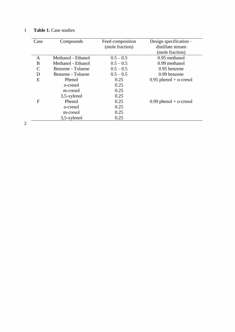
Table 1. Case studies 1
Case Compounds Feed composition
(mole fraction)
Design specification –
distillate stream
(mole fraction)
A Methanol - Ethanol 0.5 – 0.5 0.95 methanol
B Methanol - Ethanol 0.5 – 0.5 0.99 methanol
C Benzene - Toluene 0.5 – 0.5 0.95 benzene
D Benzene - Toluene 0.5 – 0.5 0.99 benzene
E Phenol
o-cresol
m-cresol
3,5-xylenol
0.25
0.25
0.25
0.25
0.95 phenol + o-cresol
F Phenol
o-cresol
m-cresol
3,5-xylenol
0.25
0.25
0.25
0.25
0.99 phenol + o-cresol
2
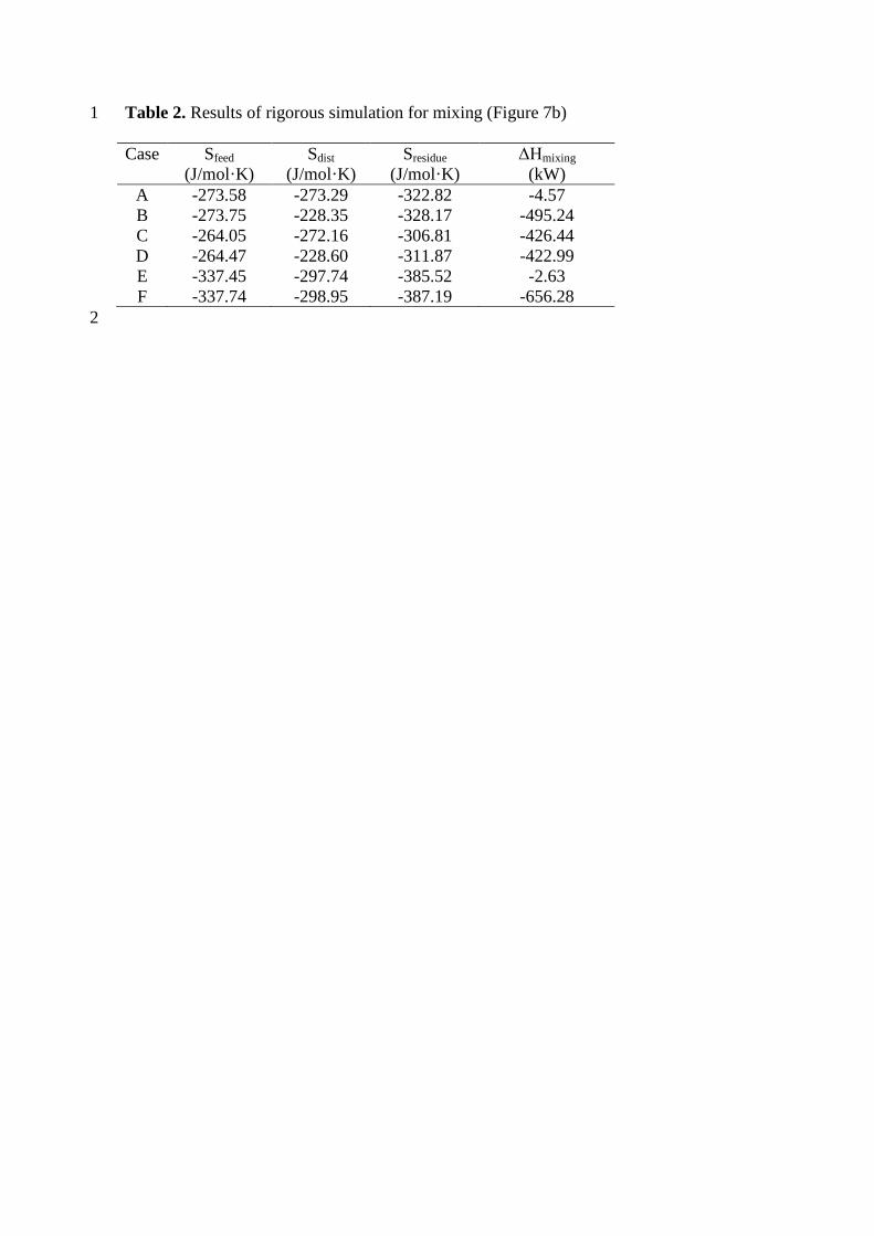
Table 2. Results of rigorous simulation for mixing (Figure 7b) 1
Case Sfeed
(J/mol·K)
Sdist
(J/mol·K)
Sresidue
(J/mol·K)
ΔHmixing
(kW)
A -273.58 -273.29 -322.82 -4.57
B -273.75 -228.35 -328.17 -495.24
C -264.05 -272.16 -306.81 -426.44
D -264.47 -228.60 -311.87 -422.99
E -337.45 -297.74 -385.52 -2.63
F -337.74 -298.95 -387.19 -656.28
2
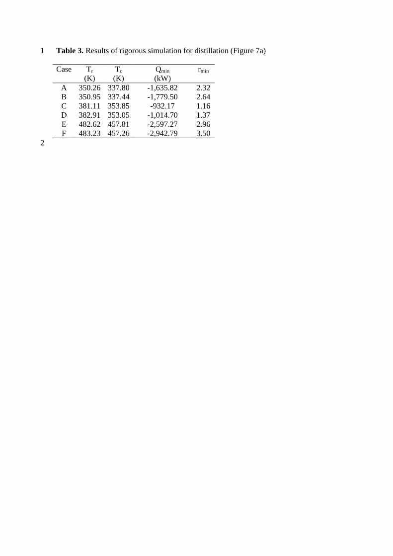
Table 3. Results of rigorous simulation for distillation (Figure 7a) 1
Case Tr
(K)
Tc
(K)
Qmin
(kW)
rmin
A 350.26 337.80 -1,635.82 2.32
B 350.95 337.44 -1,779.50 2.64
C 381.11 353.85 -932.17 1.16
D 382.91 353.05 -1,014.70 1.37
E 482.62 457.81 -2,597.27 2.96
F 483.23 457.26 -2,942.79 3.50
2
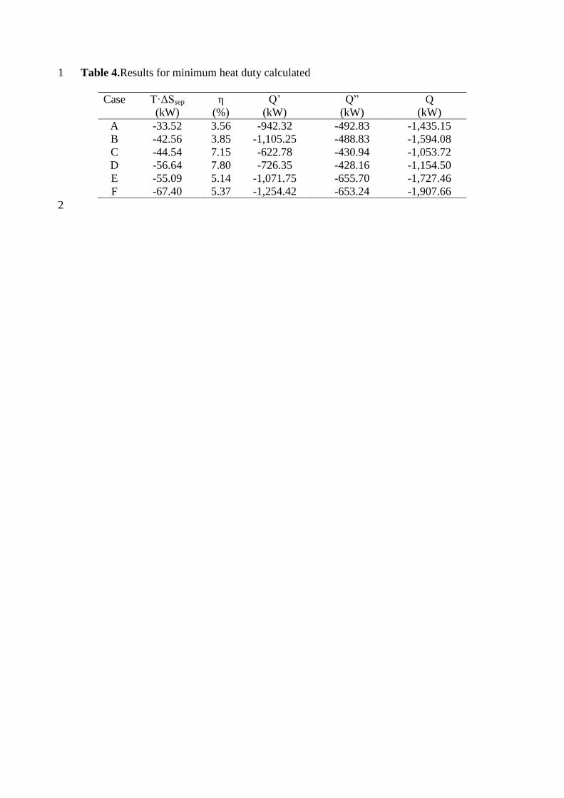
Table 4.Results for minimum heat duty calculated 1
Case T·ΔSsep
(kW)
η
(%)
Q’
(kW)
Q”
(kW)
Q
(kW)
A -33.52 3.56 -942.32 -492.83 -1,435.15
B -42.56 3.85 -1,105.25 -488.83 -1,594.08
C -44.54 7.15 -622.78 -430.94 -1,053.72
D -56.64 7.80 -726.35 -428.16 -1,154.50
E -55.09 5.14 -1,071.75 -655.70 -1,727.46
F -67.40 5.37 -1,254.42 -653.24 -1,907.66
2
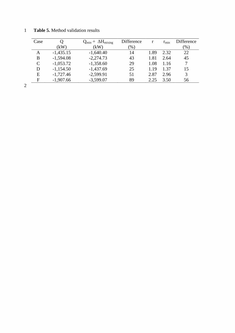
Table 5. Method validation results 1
Case Q
(kW)
Qmin + ΔHmixing
(kW)
Difference
(%)
r rmin Difference
(%)
A -1,435.15 -1,640.40 14 1.89 2.32 22
B -1,594.08 -2,274.73 43 1.81 2.64 45
C -1,053.72 -1,358.60 29 1.08 1.16 7
D -1,154.50 -1,437.69 25 1.19 1.37 15
E -1,727.46 -2,599.91 51 2.87 2.96 3
F -1,907.66 -3,599.07 89 2.25 3.50 56
2
List of Figures 1
2
Figure 1.Heat distribution in the distillation column 3
Figure 2. Thermal cycle for a distillation column 4
Figure 3.NTU validation for an equimolar mixture methanol/ethanol. 5
Figure 4.NTU validation for an equimolar mixture benzene/toluene. 6
Figure 5. NTU validation for an equimolar multicomponent mixture phenol, o-crezole, 7
p-crezole and 3,5-xylenol. 8
Figure 6. Process scheme considered for rigorous simulation 9
Figure 7. Composition column profile deviation near feed stage 10
Figure 8. Temperature and NUTs maps for ternary mixture 11
TAME/methanol/isoamylene at 4 bar. 12
Figure 9. Influence of the reaction term (residence time of 0.01 s) on the NUTs maps 13
for ternary mixture TAME/methanol/isoamylene at 4 bar. 14