minimum requirements for digital radiography …€¦ · ewert and zscherpel 1 ecndt requirements...
TRANSCRIPT

Ewert and Zscherpel 1Requirements for RT-DECNDTPraha, Oct. 20148.3Radiological
Methods
Minimum Requirements for Digital Radiography Equipment and Measurement Procedures by
Different Industries and Standard Organizations
Uwe Ewert and Uwe ZscherpelBAM Federal Institute for Materials Research and Testing,
Berlin, Germany

Ewert and Zscherpel 2Requirements for RT-DECNDTPraha, Oct. 20148.3Radiological
Methods
Introduction
- Film Radiography has been developed for quality assurance in industry over decades.
- It is basis for contractual agreements of Supplier and Purchaser.- Digital Radiography shall achieve the same image quality or better, but
with higher efficiency.
- Selected image quality requirements of different standards as ASTM, ASME and ISO are compared.
- The essential parameters for optimization and prediction of IQI visibility are discussed.
- Requirements for equipment selection are derived for CR and DDAs.
- Newly developed classification procedures for RT-D equipment are introduced.

Ewert and Zscherpel 3Requirements for RT-DECNDTPraha, Oct. 20148.3Radiological
Methods
Basic Requirements in Radiography Requirement Film DigitalStandards ISO, CEN, ASTM,
ASME ISO, CEN ASTM, ASME, MAI
Exposure Exceed minimum optical density
Exceed minimum required SNRN(Normalized Signal to Noise Ratio)
DDAs: Exceed minimum required CNRCR: expose to EPS plateau (MAI)
Detector requirements
Use required film system class or better
Use detectors which achieve the required SNRN anddo not exceed the detector unsharpness limit
Do not exceed image unsharpness limits
Maximum image unsharpness
Do not exceed the geometrical unsharpness limits
Do not exceed the image unsharpness limits
Do not exceed the image unsharpness limits
Image quality Achieve required IQI contrast sensitivity
Achieve IQI contrast sensitivity + duplex wire resolution
Achieve required IQI contrast sensitivity

Ewert and Zscherpel 4Requirements for RT-DECNDTPraha, Oct. 20148.3Radiological
Methods
Key Technologies for Film Replacement• Computed Radiography (CR) with storage
phosphor imaging plates
• Digital Detector Arrays (DDA)
CR DDA

Ewert and Zscherpel 5Requirements for RT-DECNDTPraha, Oct. 20148.3Radiological
Methods
Image Quality in Radiography- Influence of SNR and CNR -
Length
Inte
nsity Contrast
Signal(base material)
LengthIn
tens
ity Contrast
Signal(base material)
Notch visible!
Contrast/Noise is highSignal/Noise is high
Notch not visible!
Contrast/Noise is lowSignal/Noise is low
Notch is visible in the profile if C > 2.5 Noise

Ewert and Zscherpel 6Requirements for RT-DECNDTPraha, Oct. 20148.3Radiological
Methods
Typical noise sources in digital radiography:
1. EXPOSURE CONDITIONS: Photon noise, depending on exposure dose (e.g. mAs or GBqmin). This is the main factor! SNR increases with higher exposure dose.
2. Limitation for the maximum achievable SNR:
1. DETECTOR: Structural noise of DDAs and Imaging Plates also called fixed pattern noise (due to variations in pixel to pixel response and inhomogeneities in the phosphor layer).
2. OBJECT:1. Crystalline structure of material (e.g. nickel based steel,
mottling)
2. Surface roughness of test object
Noise Sources in Radiographic Images

Ewert and Zscherpel 7Requirements for RT-DECNDTPraha, Oct. 20148.3Radiological
Methods
Measurement of Contrast to Noise Ratio in DDA Practice
• CNR shall be measured in the 4T hole for proof of image quality.
• A minimum CNR of 2.5 is required by ASTM E 2698.
• This value needs to be revised!
CNR = 6.7C = I = 473Noise = 71SNR = 155
ASTM E 1025
I
I=contrastNoise
by ASTM E 2698

Ewert and Zscherpel 8Requirements for RT-DECNDTPraha, Oct. 20148.3Radiological
Methods
CNR = 2.5
CNR = 1.25
CNR = 0.625
Diameter0.12 0.25 0.5 1 2 mm
Noise = 1000Signal = 30000
50 µm pixel size
SRb image = 50 µm
Human Observer Model: Perception Threshold PT
CNRb
const SRdPT PTconst - constant human perception threshold 10
d – diameter of just visible holeCNR - contrast to noise ratioSRb – basic spatial resolution (effective pixel size)
Large area flaws are better visible than small ones at same Contrast-to-Noise Ratio
Each row has indications with same CNR = Cdepth/
Each column has holes with same diameter
Flat bottom holes of different depth and diameter
d - diameterof hole
Rose approach, 1946
ASTM E 2698 requires CNR > 2.5Needs revision!

Ewert and Zscherpel 9Requirements for RT-DECNDTPraha, Oct. 20148.3Radiological
Methods
ASTM Draft, “Practice for the Use of Digital Detector Arrays and Computed Radiology for Aerospace Casting Inspections” requires a minimum basic spatial resolution of the detector (SRb
detector) if images have been taken without magnification or
a minimum basic spatial resolution in the magnified image SRbimage).
System Selection for ASTM Standard Practice
9
imageb
SREffective pixel size of digital image ( )

Ewert and Zscherpel 10Requirements for RT-DECNDTPraha, Oct. 20148.3Radiological
Methods
ASTM Draft, “Practice for the Use of Digital Detector Arrays and Computed Radiology for Aerospace Casting Inspections” and E 2698 “Standard Practice for Radiological Examination Using Digital Detector Arrays” require for digital images with DDAs in the 2T IQI hole:
The ASTM E 2698 value (CNR = 2.5) is optimized for testing of thin objects with thickness < ½” and typical DDAs in the range of 0.1 mm < SRb < 130 µm.
Generally, CNRmin for all digital images can be described more accurate by the equation:
Verification of CNRmin for ASTM Standard Practice
holeIQI
imageb
diameterSRCNR
10min
5.2min CNR
Based on “old” Rose equation as shown before for PTconstant

Ewert and Zscherpel 11Requirements for RT-DECNDTPraha, Oct. 20148.3Radiological
Methods
Contrast Sensitivity as Required by Different Standards
Almost all standards require image quality indicators on each production radiograph.
The operator has to evaluate if the required image quality has been achieved.
He decides about acceptance or rejection of the production radiographs.
Different international standards require different contrast sensitivities, which yields different inspection quality.
The thickness sensitivity improves with material thickness.

Ewert and Zscherpel 12Requirements for RT-DECNDTPraha, Oct. 20148.3Radiological
Methods
Basic Requirements for IQI Visibility of International Standards in Comparison
ASME BPVC SC V, Ar. 2, andISO 17636-class A are about equivalent
ASTM E1742, E 2104, ISO 17636-class B are about equivalent below t=12 mm (1/2“)
Step Holes, ISO 17636-2, 2013Plate Holes, ASME BPVC SC V Ar. 2Plate Holes, ASTM E 1742, E 2104
ISO 19232-3
ISO 19232-2
ASTM E 1025

Ewert and Zscherpel 13Requirements for RT-DECNDTPraha, Oct. 20148.3Radiological
Methods
Additional Requirements for Unsharpness and Basic Spatial Resolution
In all film radiography standards the permitted geometric unsharpness (Ug) is limited and the film unsharpness is neglected.
In digital radiography the detector unsharpness (Udetector) contributes significantly to the image unsharpness (Uim) or total unsharpness(UT).
Therefore, the permitted detector unsharpness (Udetector) is limited in different standard systems, which is relevant for detector selection.
The detector unsharpness shall be always smaller than the permitted geometric unsharpness (Udetector < Ug).
The basic spatial resolution is defined as ½ unsharpness in digital radiography (SRb = ½ U).

Ewert and Zscherpel 14Requirements for RT-DECNDTPraha, Oct. 20148.3Radiological
Methods
Measurement of Basic Spatial Resolution
Duplex wire IQIISO 19232-5 ASTM E 2002
• The detector unsharpness udetector shall be controlled by reference exposures with the duplex wire IQI.
Dup
lex
Wire
IQI,
90 k
V,
1m S
DD
, sm
all f
ocus
ASTM E 2002Two new wire pairs

Ewert and Zscherpel 15Requirements for RT-DECNDTPraha, Oct. 20148.3Radiological
Methods
Standard ISO 17636-2 (2013): Table B.13, B.14 Maximum detector or image unsharpness (2SRb)
DD
A
CR

Ewert and Zscherpel 16Requirements for RT-DECNDTPraha, Oct. 20148.3Radiological
Methods
Unsharpness Requirements of Different International Standards – No International Harmonization -
0,00
0,01
0,02
0,03
0,04
0,05
0,06
0,07
0,08
0,0 1,0 2,0 3,0 4,0 5,0 6,0
Unsh
arpn
ess
in in
ch
Thickness in inch
Unsharpness requirements
E 1742 ISO 17636 class B ISO 17636 class A
MAI
E 1030 (2004)
E 1030, 1032
E 2104
Co-60, High Energy

Ewert and Zscherpel 17Requirements for RT-DECNDTPraha, Oct. 20148.3Radiological
Methods
Unsharpness Requirements in Different Int. Standards

Ewert and Zscherpel 18Requirements for RT-DECNDTPraha, Oct. 20148.3Radiological
Methods
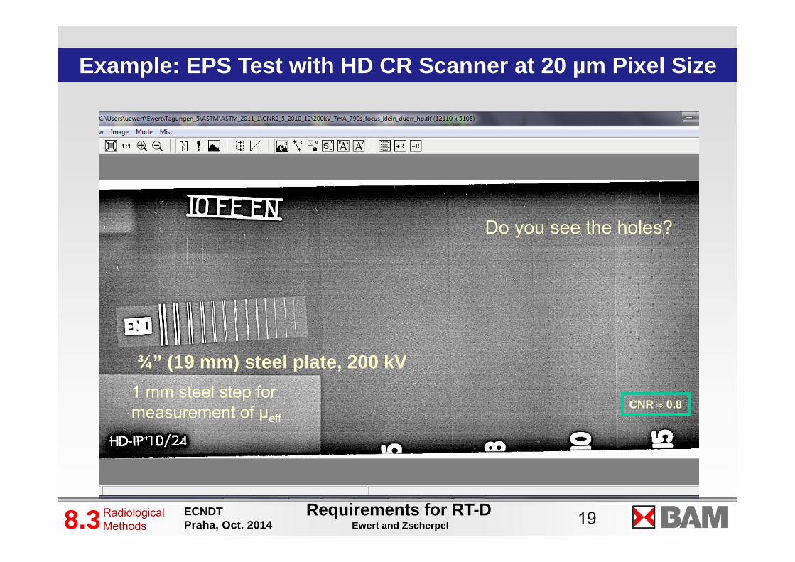
EPS – Procedure is proposed accepted for CR qualification inASTM E 20445/6 draft and the draft on “Practice for the Use of … Computed Radiology for Aerospace Casting Inspections” (USA: MAI – group)
- The EPS (equivalent penetrameter sensitivity) measurement is based on ASTM E 746
A smooth ¾ inch (19 mm) steel plate with a set of plate holes is radiographed at 200 kV in ≥ 1 m distance
The exposure is performed with different mAssettings
A graph is generated, see next pages The calculation of just visible hole diameter is
given by:
Qualification of CR-Systems- The EPS Concept -
SNRSRPTdeff
imageb
visible
PT depends slightly on operator and viewing conditionsµeff for 200 kV and 19 mm Fe is about 0,05 mm-1
ASTM E 746
New formulaEPS=
equ
ival
ent p
enet
ram
eter
sens
itivi
ty (s
ee A
STM
E 7
46, E
747
, E 1
025)
Ewert and Zscherpel 19Requirements for RT-DECNDTPraha, Oct. 20148.3Radiological
Methods
Example: EPS Test with HD CR Scanner at 20 µm Pixel Size
Do you see the holes?
¾” (19 mm) steel plate, 200 kV
CNR 0.81 mm steel step for measurement of µeff

Ewert and Zscherpel 20Requirements for RT-DECNDTPraha, Oct. 20148.3Radiological
Methods
Visibility of EPS holes (E 746)
Do you see the holes?
CNR 0.8

Ewert and Zscherpel 21Requirements for RT-DECNDTPraha, Oct. 20148.3Radiological
Methods
New Formula for Conversion of SNRN Measurements to EPS Values and Working Range for CR (ASTM Draft E 2033)
PT’ is about 2▪100 for visibility of the 2 T hole of IQIs corr. to ASTM E 1025 EPS by ASTM E 746 with 200 kV, t = 19 mm Fe plate and µeff = 0.05 mm-1
EPS= equivalent penetrameter sensitivity (see ASTM E 746, E 747, E 1025)
1
1,2
1,4
1,6
1,8
2
2,2
2,4
2,6
0 500 1000 1500 2000 2500 3000 3500 4000 450
EPS
Pixel value
EPS method for determination of performance levelsMeasured EPS,IP 1, Scanner 2 Best fit Level I level II
350
140
0 23 46 69 91 114 137 160 183 206
Dose / mGy
90% PVmax
aEPS = 1.16
SNRµSR
tPTEPS
eff
imageb
testplate
'
Level II: PV 140 – 4095
Level I: PV 350 – 4095
Plateau range

Ewert and Zscherpel 22Requirements for RT-DECNDTPraha, Oct. 20148.3Radiological
Methods
Old CR Classification Scheme
Classification scheme of ASTM; e 2446, EN
14784-1 and ISO 16371-1 by system classes.
The CR systems are classified by the
maximum achievable SNRN (IP 1 – 6) and the basic spatial detector
resolution SRbdetector (Y).
System class CEN
Minimum normalised SNR
IP 1/Y 130
IP 2/Y 117
IP 3/Y 78
IP 4/Y 65
IP 5/Y 52
IP 6/Y 43 Note 1: The normalized SNR values of Table 1 are similar to those of EN 584-1. They are calculated by SNR= log(e) (Gradient/Granularity) of Table 1 in EN 584-1. The measured SNR values are calculated from linearised signal data.

Ewert and Zscherpel 23Requirements for RT-DECNDTPraha, Oct. 20148.3Radiological
Methods
New CR Classification SchemeNew classification by performance levels as given in the
draft revision of ASTM E 2446 (2014).
Additionally, a specified EPS performance is required.
CR System Classification
Minimum SNRN (normalized to SRb=88.6 µm)
Maximum iSRb
detector
value [µm]
Maximum achieved EPS by E 746 [%]
CR Special 200 50 1.00 CR Level I 100 100 1.41CR Level II 70 160 1.66CR Level III 50 200 1.92

Ewert and Zscherpel 24Requirements for RT-DECNDTPraha, Oct. 20148.3Radiological
Methods
Qualification “Spidernet” Graph and Classification Statement
02468
101214
SRbdetector = 145µm
Csa = 0,8
aEPS@mag 1 = 1,65
Efficiency@1mGy = 115
ISO Speed@SNRN130 = 400
aSNRN = 88
Qualification of CR‐System XY
Performance level II
Achievable EPSSpecific for CR
Efficiency as defined for DDAs in E 2597
Speed as defined for film
Achievable SNRN for ISO 17636-2 user
Achievable CS for E 2597 user
Interpolated SRbdetector for
E 2795, ISO 17636-2 users

Ewert and Zscherpel 25Requirements for RT-DECNDTPraha, Oct. 20148.3Radiological
Methods
Required Test for ASTM E 2445/2446 Required ResultGeometric Distortion Fail if distortion > 2%Laser Jitter Not permitted, Laser Beam Scan Line Integrity Not permittedScan column dropout Not permittedScanner Slippage Not permittedImaging plate Artifacts Not permittedErasure Fail if > 2%Shading or banding Fail if more than ±10%
Test results shall be reported,classification is possible in case of exceeding the limits
Result to report
PMT Non-linearity Report if > 2%Burn-In Report if > 2%Spatial Linearity < 2%Imaging plate response variation Report if > ±10%
Optional test on request Result to reportImaging Plate Fading (no test object required), optional test Report fading in %,
New Qualification Procedures

Ewert and Zscherpel 26Requirements for RT-DECNDTPraha, Oct. 20148.3Radiological
Methods
Requirements for Digital Detector Arrays
DDAQualification by ASTM E 2597M

Ewert and Zscherpel 27Requirements for RT-DECNDTPraha, Oct. 20148.3Radiological
Methods
FujiFilm IX25SNRN ~ 265
PerkinElmer 1620SNRN ~ 1500Magn. = 3.5
DDA Technology provides better image quality than film with aspecial calibration procedure!
Best (slowest) NDT film
DDA exposure
Images high pass filtered for better presentation
BAM 5, 8mm steel

Ewert and Zscherpel 28Requirements for RT-DECNDTPraha, Oct. 20148.3Radiological
Methods
Qualification of Digital Detector Arrays- Management of Underperforming Pixels -
Definition and Test of Bad Pixels:6.2.1.1 Dead Pixel6.2.1.2 Over Responding Pixel6.2.1.3 Under Responding Pixel6.2.1.4 Noisy Pixel 6.2.1.5 Non-Uniform Pixel 6.2.1.6 Persistence/Lag Pixel 6.2.1.7 Bad Neighborhood Pixel
6.2.2 Types or Groups of Bad Pixels:
6.2.2.1 Single Bad Pixel6.2.2.2 Cluster of Bad Pixels 6.2.2.3 A cluster without any CKP is well correctable. 6.2.2.4 A cluster with CKP is labeled a relevant cluster. 6.2.2.5 A single bad line segment is a special irrelevant cluster.
A bad pixel can be corrected if it has at least 5 good neighbors
ASTM E 2597M

Ewert and Zscherpel 29Requirements for RT-DECNDTPraha, Oct. 20148.3Radiological
Methods
Qualification of Digital Detector Arrays- Pixel Coverage Recommendations -
ASTM E 2736

Ewert and Zscherpel 30Requirements for RT-DECNDTPraha, Oct. 20148.3Radiological
Methods
Qualification of Digital Detector Arrays- Management of Underperforming Pixels -
ASTM E 2736
Compensation Principles

Ewert and Zscherpel 31Requirements for RT-DECNDTPraha, Oct. 20148.3Radiological
Methods
Compensation Principle (II) of ISO 17636-2
Compensation of high detector unsharpness by increased SNR
• Unsharp digital systems may be applied for NDT if they enable to compensate the missing sharpness by increased SNR.
• That means, achieves a digital system not the required visibility of the separated duplex wires, it can be used for NDT, if one or two single wires more than required (see tables B.1 –B.12 of ISO/DIS 17636-2) can be seen clearly in the digital image for one or two missing duplex wire pairs. Compensation of 3 wires vs. wire pairs requires agreement of contracting parties.
• Compensation principle (II):• High detector unsharpness can be compensated by
increased SNR 31

Ewert and Zscherpel 32Requirements for RT-DECNDTPraha, Oct. 20148.3Radiological
Methods
Example : Compensation Principle (II) of ISO 17636-2
Compensate missing spatial resolution by increased single wire sensitivity:• A lower spatial resolution i.e. a lower double wire score (D)
may be compensated by a higher single wire sensitivity i.e. higher single wire score (W).
• Max. two (or three) single/double wire scores may be exchanged.
Required:
D12W14
NotOKD13W13
OK:
D11W15
OK
D10W16
OKby agreement
D9W17
Duplex wire score
Single wire score
Interesting for detectors with higher unsharpness

Ewert and Zscherpel 33Requirements for RT-DECNDTPraha, Oct. 20148.3Radiological
Methods
Qualification of Digital Detector Arrays- Efficiency Measurement -
Qualification by ASTM E 2597M
120 kV, 40 mm Al
220 kV, 40 mm Al
90 kV
50 kV160 kV
120 kV, 3 mm Cu

Ewert and Zscherpel 34Requirements for RT-DECNDTPraha, Oct. 20148.3Radiological
Methods
Qualification of Digital Detector Arrays- Image Lag -
Qualification by ASTM E 2597M
Important for CT and fast measurements as e.g. automated defect recognition (ADR).

Ewert and Zscherpel 35Requirements for RT-DECNDTPraha, Oct. 20148.3Radiological
Methods
Qualification of Digital Detector Arrays- Contrast Sensitivity by CNR-Step Wedge Measurement -
Qualification by ASTM E 2597M
Contrast sensitivity (CA) at 5% notch in a step wedge by 1/CNR
Step wedge with notch
Measure contrast and noise per step

Ewert and Zscherpel 36Requirements for RT-DECNDTPraha, Oct. 20148.3Radiological
Methods
Qualification of Digital Detector Arrays- Contrast Sensitivity by CNR-Step Wedge Measurement -
Qualification by ASTM E 2597M
Working range (4s)

Ewert and Zscherpel 37Requirements for RT-DECNDTPraha, Oct. 20148.3Radiological
Methods
Qualification of Digital Detector Arrays- SMTR by SNR-Step Wedge Measurement -
Qualification by ASTM E 2597M
Specific Material Thickness Range by SNR limits
SNR = 250
SNR = 130
Qualification by ASTM E 2597M

Ewert and Zscherpel 38Requirements for RT-DECNDTPraha, Oct. 20148.3Radiological
Methods
Qualification of Digital Detector ArraysDDAs are qualified by different tests of ASTM E 2597.Five relevant parameters shall be provided: Basic spatial resolution (SRb) Specific Material Thickness Range Efficiency Image lag Contrast sensitivity
38
Qualification by ASTM E 2597M

Ewert and Zscherpel 39Requirements for RT-DECNDTPraha, Oct. 20148.3Radiological
Methods
Conclusions Replacement of film radiography by digital techniques in NDT requires careful selection of
suitable digital detectors. Standards on digital radiography were published and revised since 2005 in ISO, CEN, ASTM
and ASME, defining requirements for image quality and detector selection. International standards define different requirements for image quality and detector selection. The image quality depends on the essential parameters: specific contrast µeff, SNR and basic
spatial resolution SRb. CR is accepted as film replacement technology:
The prove of image quality requires SNRN measurements and IQI visibility (ISO 17636-2).
CR classification and qualification is under major revision. Classification will consider SNRN, SRb
detector and EPS DDAs achieve a significantly better contrast sensitivity with suitable detector calibration than
film radiography. The prove of image quality requires CNR measurements and IQI visibility (ASTM practice
E 2798). DDAs are qualified by different but similar procedures than CR systems, because the DDA
detector calibration and image integration influences seriously the qualification, and DDAs provide currently better image quality than CR.

Ewert and Zscherpel 40Requirements for RT-DECNDTPraha, Oct. 20148.3Radiological
Methods
End