minimum sonic-boom overpressures for …...tech library kafb, nm nasa technical paper 1820 0334760...
TRANSCRIPT

"
NASA Technical Paper 1820
Charts for Determining Potential Minimum Sonic-Boom Overpressures for Supersonic Cruise Aircraft
Christine M. Darden
MARCH 198 1
https://ntrs.nasa.gov/search.jsp?R=19810012487 2020-03-27T01:49:32+00:00Z

TECH LIBRARY KAFB, NM
NASA Technical Paper 1820 0334760
Charts for Determining Potential Minimum Sonic-Boom Overpressures for Supersonic Cruise Aircraft
Christine M. Darden Lartgley Research Center Hampton, Virginia
National Aeronautics and Space Administration
Scientific and Technical Information Branch
1981

SUMMARY
Charts are presented which will provide a rapid estimation of minimum achievable sonic-boom levels for supersonic cruise aircraft. These charts were obtained by using a minimization method based on modified linear theory. Results are shown for several combinations of Mach number, altitude, and air- craft length and weight. For each of these conditions, overpressure and impulse values are given for two types of sonic-boom signatures: ( 1 ) a "flat-top" or minimum-overpressure signature which has a pressure plateau behind the initial shock and (2 ) a minimum-shock signature which allows a pressure rise after the initial shock. Some results are also given for the effects of nose shape. An example of the use of the charts has been included.
INTRODUCTION
Sonic-boom minimization research has led to the following significant developments. The concepts of "signature freezing" (ref. 1 ) and a far-field minimum boom (ref. 2) combined with the basic sonic-boom theory (refs. 3 and 4) led to the mid-field minimization theory of reference 5. These results, ini- tially limited to an isothermal atmosphere, were first modified to provide for signature propagation in the standard atmosphere (ref. 6) and then modified again to permit trade-offs between sonic-boom shock levels and nose bluntness by introducing the concept of "nose-length" ratios (ref. 7). The computer pro- gram incorporating the above theories, as presented in reference 7, calculates both the minimizing-pressure signature and the required equivalent-area distri- bution for a given cruise Mach number, altitude, and aircraft length and weight. Using area distributions from this program as constraints for the design of three low-boom wind-tunnel models, this minimization procedure has been verified experimentally (refs. 8 and 9) .
To allow rapid evaluation of the minimum sonic-boom characteristics avail- able at cruise for transport aircraft, this report provides a convenient series of charts which show overpressure levels, shock levels, and impulse levels for minimum-overpressure signatures and two different minimum-shock signatures. Also included are results for three different "nose-length" ratios. The charts cover a range of Mach numbers, altitudes, and aircraft lengths and weights which are believed to be typical values for future generation supersonic transports.
SYMBOLS
Values are given in both SI and U.S. Customary Units. The measurements and calculations were made in U.S. Customary Units.
Ae equivalent area
CD drag coefficient

h a i r p l a n e a l t i t u d e
I impulse of p res su re s igna tu re ,
k r e f l e c t i o n factor
1 equ iva len t l eng th
M Mach number
AP overpressure
W a i rp lane weight
X a x i a l d i s t a n c e
x nose-bluntness parameter
rl r e l a t i v e r ise i n p r e s s u r e b e h i n d t h e i n i t i a l s h o c k i n p r e s s u r e s i g n a t u r e ( 0 < rl < 1 , see r e f . 7)
Subsc r ip t s :
1 equ iva len t l eng th a t 1
0 minimum ove rp res su re s igna tu re
r r e fe rence cond i t ions
S minimum shock s ignature
max maximum o v e r p r e s s u r e i n minimum shock s igna tu re
MINIMUM SONIC BOOM
Types o f S igna tures
The term "minimum s o n i c b o o m " is ambiguous i n t h a t a t least t h r e e d i f f e r e n t va lues o f t he p re s su re s igna tu re may be minimized: ( 1 ) t h e i n i t i a l s h o c k , ( 2 ) t he ove rp res su re l eve l , and ( 3 ) the impulse. The d i f f e r e n c e s i n t h e result- ing s igna tu re shapes are q u i t e s ignif icant , depending on which value is mini- mized. R e s u l t s f o r t h e f i r s t two of t h e s e s i g n a t u r e s h a p e s are p r e s e n t e d i n t h i s paper. I f t h e o v e r p r e s s u r e is minimized, the asqociated pressure s i g n a t u r e is f l a t from t h e i n i t i a l shock to the expans ion r eg ion o f t he s igna tu re as i l lus t ra ted i n f i g u r e 1 . I f t h e s h o c k is minimized , then overpressure l eve ls are allowed t o rise fo l lowing t he i n i t i a l shock . The rate of rise i n t h i s s i g - n a t u r e is c o n t r o l l e d by rl which can have a value f rom 0 to 1 . O ( r e f . 7) . When rl has a value of 1 . O , t h e r e s u l t i n g s i g n a t u r e is an 'IN-wave." An q value of z e r o i n d i c a t e s a " f l a t - top" s igna tu re . Typ ica l va r i a t ions o f impu l se and i n i - t i a l shock with rl are shown i n f i g u r e 1 . Note t h a t t h e i n i t i a l shock Ap d e c r e a s e s l i n e a r l y w i t h q and t h a t impulse I i n c r e a s e s l i n e a r l y w i t h q.
2

Recent experimental w o r k a t the Un ive r s i ty o f Toron to on "outdoor- d i s t u r b a n c e " l e v e l s i n d i c a t e s t h a t p r e s s u r e rises f o l l o w i n g t h e i n i t i a l s h o c k add very l i t t l e a d d i t i o n a l d i s t u r b a n c e ( r e f . 1 0 ) . These pressure rises do, how- ever, produce large b e n e f i t s i n a i r p l a n e w e i g h t . I n t h e s e e x p e r i m e n t s , minimum- shock s ignatures developed by the methods of reference 7 were produced on a loud-speaker driven system and human r e a c t i o n to t h e boom l e v e l s were obtained.
Vehicle Parameters
The min imiz ing-area d i s t r ibu t ion and , thus , the resu l t ing p ressure s igna- tures are a f f e c t e d g r e a t l y by the a i rp lane l ength , weight , and "nose- length ." Resu l t s shown i n f i g u r e 2 c l e a r l y i n d i c a t e t h a t lower weights and/or increased l eng ths w i l l s i g n i f i c a n t l y i m p r o v e t h e sonic-boom c h a r a c t e r i s t i c s o f a n a i r c r a f t . T h e s e r e s u l t s were o b t a i n e d u s i n g t h e " f l a t - t o p " s i g n a t u r e , b u t t r e n d s are t h e same when t h e minimum-shock s i g n a t u r e is c a l c u l a t e d .
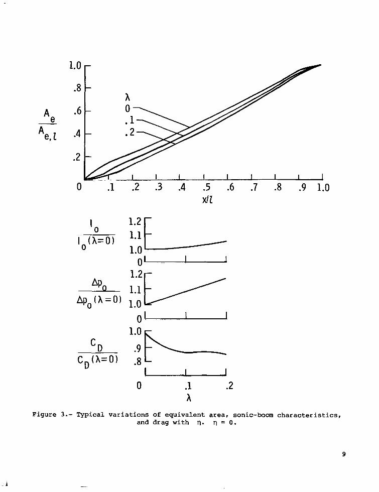
A s d i s c u s s e d i n r e f e r e n c e 5, t h e e q u i v a l e n t area f o r minimum s o n i c boom has an i n f i n i t e g r a d i e n t a t x = 0. Th i s b lun tness is no t cons i s t en t w i th shapes needed for l o w wave drag. As a compromise, a nose-bluntness parameter X or "nose-length" ra t io is d e f i n e d ( r e f . 8 ) . A va lue o f X = 0.1 i n d i c a t e s t h a t t h e area u p to 1/10 t h e t o t a l l eng th has been changed to a sharper c u s p l i k e reg ion as s e e n i n f i g u r e 3. Values of X normally range from 0 to 0.2. The e f f e c t s o f t h e s e c h a n g e s i n t h e n o s e e q u i v a l e n t area on drag, overpressure, and impulse are also shown i n f i g u r e 3. A s the nose-bluntness parameter X i n c r e a s e s , l e v e l s of drag decrease as expec ted , bu t t he re is a corresponding increase in the l eve ls o f overpressure and impulse . This s tudy was made w i t h bodies of revolut ion corresponding to these equ iva len t areas being used to g e t approximate drag increments.
F l i g h t C o n d i t i o n s
T y p i c a l e f f e c t s o f a l t i t u d e a n d Mach number on overpressure and impulse l e v e l s are shown i n f i g u r e 4 . Note t h a t o v e r p r e s s u r e l e v e l s i n c r e a s e w i t h Mach number o v e r t h e e n t i r e r a n g e shown and w i th a l t i t ude ove r most of the range shown. There is a decrease in impulse wi th Mach number but an increase i n t h e e q u i v a l e n t area causes t h e impulse to i n c r e a s e w i t h i n c r e a s i n g a l t i t u d e .
PRESENTATION OF CHARTS
Figures 5 to 1 6 o f t h i s report g ive results from the minimizat ion program f o r f l i g h t / d e s i g n parameters f o r t y p i c a l s u p e r s o n i c cruise a i r c r a f t . Mach num- bers range from 2.5 to 3.5, weights range from 180 000 k g t o 320 000 kg (400 000 l b to 700 000 l b ) , a l t i t u d e s r a n g e f r o m 1 5 km to 30 km (50 000 f t to 1 00 000 f t ) , and lengths range f ran 73 m to 11 0 m (240 f t to 360 f t ) . R e s u l t s are shown for minimum-overpressure signatures (Tl = 0 ) and for two minimum-shock s i g n a t u r e s (Tl = 0.5 and 0 . 9 ) . "Nose-length" ra t ios X of 0, 0.1, and 0 .2 are shown fo r eve ry case. A g round r e f l ec t ion f ac to r o f 2 has been used in a l l cases. Corresponding area d i s t r i b u t i o n s are no t p re sen ted bu t are a v a i l a b l e through use of the computer program of r e fe rence 7. The 1962 Standard Atmosphere
3

Tables ( r e f . 1 1 ) have been used i n a l l c a l c u l a t i o n s . The fol lowing table g i v e s a n o v e r v i e w o f a v a i l a b l e i n f o r m a t i o n p r e s e n t e d i n f i g u r e s 5 to 16:
r Figure
5
6
7
8
9
1 0
11
1 2
1 3
1 4
1 5
1 6
Reference to c h a r t s
Abscissa
2
h
W
h
W
2
M
h
W
M
M
1
Three va lues shown i n c h a r t s
h
2
h
W
1
W
h
M
M
W
1
M
The base values used f o r p e r t u r b a t i o n o f t h e s e parameters are M = 3 . 2 W = 283 495 kg (625 000 l b ) , 2 = 94.49 m (31 0 f t ) , h = 24.384 km (80 000 f t ) .
EXAMPLE OF CHART APPLICATION
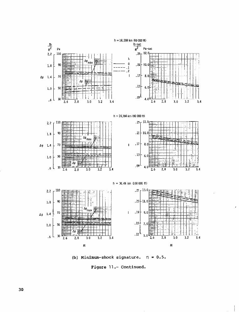
A s an example of the use of the char ts , consider the determinat ion of t h e b e s t a c h i e v a b l e sonic-boom leve l o f an a i r c ra f t wh ich is 94.49 m (310 f t ) i n length and which cruises a t a Mach number of 2.7 a t 18.288 km (60 000 f t ) . The s t a r t of cruise weight is 283 495 kg ( 6 2 5 000 l b ) . A sonic-boom estimate f o r these condi t ions us ing a minimum-overpressure signature is g i v e n i n f i g - ure 11 (a) . A t Mach 2.7 , t h e best ach ievab le Ap is a b o u t 47.3 Pa (0 .99 l b / f t 2 ) . For relaxed nose bluntness, x = 0.1 and 0.2, t he va lues o f Ap i n c r e a s e t o 51.1 and 55.2 Pa (1 .07 and 1 .15 l b / f t 2 ) , r e s p e c t i v e l y .
4

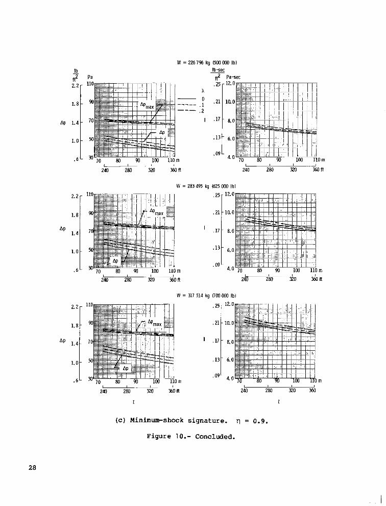
I f i n s t e a d o f t h e " f l a t - t o p " s i g n a t u r e , t h e i n t e r m e d i a t e f i n i t e - r i s e s i g - na tu re (Tl = 0.5) is chosen , the overpressure estimates are located i n f i g - u r e 11 (b) . For t h e b l u n t (x = 0) case, the shock overpressure Ap is about 43 Pa (0 .9 lb / f t2) and the cor responding maximum overpressure A h a x is about 72 Pa (1 .5 l b / f t 2 ) . A g a i n , s l i g h t i n c r e a s e s are shown as x increases to 0.1 and 0.2. V a l u e s of the shock Ap and t he maximum ove rp res su re fo r a very steep minimum-overpressure signature (q = 0.9) are s e e n i n f i g u r e 11 ( c ) . A t x = 0, t h e l e v e l of Ap is a b o u t 40 Pa ( 0 . 8 5 l b / f t 2 ) a n d t h e maximum overpressure l e v e l i n c r e a s e s to roughly 93 Pa (1 .94 l b / f t 2 ) . Impulse l e v e l s are r e a d i n a l i k e manner from the co r re spond ing f i gu res on t he r i gh t .
Q u i c k estimates, as p rev ious ly shown, c a n e a s i l y be made fo r o the r des ign / c r u i s e parameters. The complete p res su re s igna tu re and t he equ iva len t - a rea d i s - t r i b u t i o n c a n be ob ta ined by u s i n g t h e computer program of reference 7 . The des ign of an a i r c r a f t to match an equiva len t -a rea d i s t r ibu t ion is d e s c r i b e d i n r e fe rences 8 and 9 . This equ iva len t area is composed o f a i r c r a f t volume, l i f t - ing forces , d i sp lacement th ickness , and exhaus t plumes. Freedom is allowed i n the arrangement of these va r ious con t r ibu t ions t o t h e total-area d i s t r i b u t i o n .
The na ture o f the min imiz ing-area d i s t r ibu t ion sugges ts genera l des ign fea- tures which may be needed i n o r d e r to meet t h e t o t a l area cr i ter ia . Among t h e s e d e s i g n f e a t u r e s are an ex tended l i f t i ng su r f ace , b lun t nose r eg ion , l ong equ iv - a l e n t l e n g t h , and d ihedra l . Many of t h e s e f e a t u r e s p r e s e n t some problems and w i l l thus require some compromise.
Langley Research Center Nat ional Aeronaut ics and Space Adminis t ra t ion Hampton, VA 23665 February 1 9, 1 981
5

1. Hayes, Wallace D.: Linearized Supersonic Flow. Ph. D. Thesis, California Inst. Technol., 1947. (Also available as North American Aviation Rep. No. AL 222.)
2. Jones, L. B.: Lower Bounds for Sonic Bangs in the Far Field. Aeronaut. Q., vol. XVIII, pt. 1 , Feb. 1967, pp. 1-21 .
3. Whitham, G. B.: The Flow Pattern of a Supersonic Projectile. Commun. Pure & Appl. Math., vol. V, no. 3, Aug. 1952, pp. 301-348.
4. Carbon, H. W.; and Maglieri, D. J.: Review of Sonic-Boom Generation Theory and Prediction Methods. J. Acoust. SOC. America, vol. 51, no. 2, pt. 3, Feb. 1972, pp. 675-685.
5. Seebass, R.; and George, A. R.: Sonic-Boom Minimization. J. Ac0us.t. sot. America, vol. 51 , no. 2, pt. 3, Feb. 1 972, pp. 686-694.
6. Darden, Christine M.: Minimization of Sonic-Boom Parameters in Real and Isothermal Atmospheres. NASA TN D-7842, 1975.
7. Darden, Christine M.: Sonic-Boom Minimization With Nose-Bluntness Relaxa- tion. NASA TP-1348, 1979.
8. Mack, Robert J.; and Darden, Christine M.: Wind-Tunnel Investigation of the Validity of a Sonic-Boom-Minimization Concept. NASA TP-7421, 1979.
9. Mack, R. J.; and Darden, C. M.: Some Effects of Applying Sonic Boom Minimi- zation to Supersonic Cruise Aircraft Design. J. Aircr., vol. 17, no. 3 , Mar. 1 980, pp. 182-1 86.
10. Niedzwiecki, A.; and Ribner, H. S.: Subjective Loudness of "Minimized" Sonic Boom Waveforms. J. Acoust. SOC. America, vol. 64, no. 6, Dec. 1978, pp. 1622-1 626.
1 1 . U.S. Standard Atmosphere, 1962. NASA, U.S. Air Force, and U.S. Weather Bur., Dec. 1962.
6

Minim urn Minimum
0 .5 1.0
rl
Figure 1.- Typical variations of shock and impulse levels with rl.

I I r
Figure
"" Reference conditions:
*Pr I = 6.48 Pa-sec r
= 45.51 Pa
n
W = 272 155 kg
1 = 91.44 rn r
r
0 1 2 0 1 2
WIW r 111 r 2.- Variations in sonic-boom characteristics with airplane parameters.
M = 2.7; h = 18 288 m; 17 = 0.
8
A e
1.0
.8
.6
.4
.2
0
0 .1 .2 h
i
9

"" Reference conditions: h = 18 288 m M =2.7
r
! I I J
l o 8 r
I 1 I ~-
1 2 3 M
*% = 45.51 Pa
I r = 6.48 Pa-sec
r 1"""- I I
L 1 I .~ I
1 1 I I I
! I
I I I
"""_ """_
1 . - I I 0 1 2
h Ih
-
r Figure 4.- Variation of sonic-boom characteristics with operational parameters.
W = 272 155 kg; 2 = 91 .44 m; q = 0.
10

h = 18.288 km (60 OOO R)
loo i 1.6- 8 o L
4l 1.2- 601
1 L
.8-
4
2.0-
1.6 -
1.2 -
. 8 -
. b-
2.0 -
1.6 -
1.2 -
. 8 -
. 4 -
*I9- 9.0
A
.I
. 2
- I 7 - 8.0
' .15- 7.0
.13 - 6.0
.I1 - 5.0 O m
I I I I I , I I
240 280 320 3 6 O f f 240 280 320 ?aft
h=24.?84krn l 80000f l )
I
.21- IO.
.19- 9.
. 1 7 - 8.
.15-
* 13 6
I I I I I I
240 280 320 360 fl 240 280 320 360 fl
h = 30.48 krn (1OOooO ft)
100
80
60
40
2o 70 80 90 100 110 rn I I I I
240 280 320 360fl
I
.27 -
.25 -
.23 -
.21 -
.I9 70 80 90 100 110
1 rn
240 280 320 360 fl I I I
(a) "Flat-top" signature.
Figure 5.- Variation of overpressure and impulse with length. M = 3.2; k = 2.0; W = 283 495 kg (625 000 lb) .
11

4
4
2.0-
1.6 -
1.2 -
.8 -
. 4 -
2.0-
1.6 -
1.2 -
.8 -
.4’
2.0 -
1.6 -
1.2 -
.8 -
.4 -
”
h 0
.1
.2 I
Ib-sec ft2 Pa-sec .21 -
.19 -
.17 -
.15 -
.13 -
1 I I I I !
240 280 320 % O f t 240 280 320 360 ft
h=24.384km (8OooOftl
I
10.0
6.0 1 I I , I
240 280 320 % O f t 240 280 320 360 ft
h=M.48km(100000f t )
m
240 280 320 360 ft 1
I I
I
L m
240 280 320 360 ft 1
I I
(b) Minimum-shock signature. q = 0.5.
Figure 5.- Continued.
12

h = 18.288 km (60 OOO ff 1
Ib-sec f12 Pa-sec
2.0-
1.6-
1.2-
. 8 -
.4-
h 0
.1
. 2
I
"_" "_
m
.21-
.19-
10.
9.
- 8.
.15- 7.
.13- 6.
I I f J , I I
240 280 320 36Oft 240 280 320 mff
h = 24.384 km (80 OOO ff 1
I
.O m I I I
240 280 320 % O f t
h=?0.48km(100000f f )
"*" 70 80 90 1M) 110
2.0-
1.6 -
hp 1.2-
.8 -
.4- I I I
240 280 320 360 ff I
m I
280 320 360 ff
80 90 100 110 m I I
280 320 360R 2
(c) Minimum-shock signature. 0 = 0.9.
Figure 5.- Concluded.
13

2.0-
1.6-
4 1.2-
.a -
.A-
2.0.
1.6.
4 1.2.
. a .
.41
2 = 76.20 m (250 f t )
Ib-sw f12 Pa-sec
.27 - h
0 . 2 3 - ""_ . I .2 "_
I .I9 -
.15 -
.ll - km
I
Z = 106.68 m (350 f t )
4
2.0-
1.6-
1.2-
. 8 -
.4-
50 60 70 80 h
- 1 bo 1dox103 f t
I
.27-
.23-
.19-
.15-
.11-
50 60 7'0 io sb 1b0 X lo3 ft h
(a) "Flat-top" signature.
14

Z = 76.20 m (250 f t )
Ib-sec ft2 Pa-sec
5.0 15 19 23 27 31 km
h 0 _"" . 1
.2
I
"_
km
50 60 7 b rio do 1box 103, I I I I
50 60 7 b io 40 1dOx 103ft
Z = 94.49 m (310 f t )
2.0 - 100
1.6 - 80
Ap 1.2 - 60
. a - 40
. 4 - 2o 15 19 23 27 31 km km
Z = 106.68 m (350 f t )
5*0 15 19 23 27 31 km
(b) Minimum-shock signature. 0 = 0.5.
Figure 6.- Continued.
15

2 = 76.20 m (250 f t )
- Ib Pa, ft2
Ib-sec Pa-sec ft2
2.2 - 110 .n - 13.0 A
1.8 - .23-11.0 ""_ .1 .2 "_
dp 1.4 - 70 I .19- 9.0
1.0 - 50 ' I 5 - 7 .0
.6 30 15 19 23 27 31 km km
4
2.2 -
1.8 -
1.4 -
1.0 -
. 6
2.2 - 110
1.8 - 90
1.4 - 70
1.0 - 50
. 6 - 30
Z = 94.49 m 1310 f t )
I
.25-
.23-
.19-
.15-
.11-
1 1 1
M 60 70 80 ~
I = 106.68 m (350 f t )
I
.25- 13'
.23 - 11.
.19- 9.
.13- 7.
.ll- 5.
km h 6b 7'0 80 90 loOX103ft
I 1 " l
. knl
(c) Minimum-shock signature. ?l = 0.9.
Figure 6.- Concluded.
16

h=18.288km(60OOOft) Ib-sec ft2 Pa-sec
PP
2.0 - 100
1.6 - 8o
1.2 - 60
.8 - 40
. 4 - 20
A 0
. I
. 2 I
x lo3 kg
h = 24.384 km ( 8 0 OOO i t )
2.0- 100 .25 - 12.0
1.6 - .21 - I0.O
4 1.2 - 60
I - 8.0
.a - 40 - 6.0
x IO3 kg -09 - 4.0 0 x IO3 kg
4bo 5b 6b 7 h x I O 3 I b 4b 5 t h 6bO 7kIx1O3Ib
2.0- 1
1.6 -
Ap 1 .2 -
.8 -
.4L
I
x lo3 kg
.27 -
.23 -
.I9 -
.15 -
.I1 - x IO3 ks
(a) "Flat-top" signature.
I
Figure 7.- Variation of overpressure and impulse with weight. M = 3.2; k = 2.0; 1 = 94.49 m (310 ft).
17

.. -
h = 18288 km (60 OOO ft)
" Ib
,2 Pa *p5-12.0
A 0
.2 - 1 .21-10 .0
I -17 - 8.0
e l 3 - 6.0
'09- 4.0 160 200 240 280 MOx 103kg
400 500 600 i b o x 1031b - 400 5b0 6b0 & X 1031b
.21 - 10.0
I - 8.0
. 1 3 - 6.0
*09- 4.0 240 280 MOx lo3 kg
4bo 500 6bo 7bO X lo3 Ib I
h = 30.48 km (100ooO f t )
400 ;bo 800 i00x1031b 4bO 5b0 6bO 7bOx IO3 Ib
w w
(b) Minimum-shock signature. q = 0.5.
Figure 7.- Continued.
18

2.0-
1.6 -
1.2 -
.8 -
. 4 -
T 1, f T
-r I i 0
h = 18.288 km (60 Ktl ft)
Ib-sx ft* Pa-sec
."_
."
IO3 kq
h 0
. I
.2
I
12.0
, lo . 0
8.0
6.0
4.0 160 200 240 280 320
4b 500 6bo 7bOX 1031b 4do sbo $00 7b0x1O3Ib
h = 24.384 km (80 Ktl ft)
I
x IO3 kg
4k 5 k l 6bo 7 b X 1 0 3 1 b
.25-
.21 -
.17 -
.13-
.09- x lo3 ks
4bo 5&J Sdo 7boX 1O3Ib
w
(c) Minimum-shock signature. rl = 0.9.
Figure 7. - Concluded.
19

I
Ib Pa
W = 226 7% kg (500 MM Ib) Ib-see
#2 Pa-sec 2.2 -
1.8 - 90
Ap 1.4 - 70
1.0 - 50
- 6 - 3o 15 19 23 27 31 km 4'0 15 19 23 27 31 km
;O 60 70 80 90 lo0 X 103ft , I 50 i o i o 8b do 1b0 x 103ft
W = 283 495 kg (625 MM Ib)
W = 317 514 kg OOO Ib)
(a) "Flat-top" signature.
Figure 8.- Variation of overpressure and impulse with altitude. M = 3.2; k = 2.0; 1 = 94.49 m (310 ft).
20

Ib - fl2 2.2
1.8
Ap 1.4
1.0
.6
Pa
W = 226 7% kg (500 OOO Ib) Ib-sec
,,2 Pa-sec
A 0
.1
.2
I
""_ "_
km
T t :I: T T
1 T 19 23 27 31 km
AP
2.2 r
1.8 -
1.4 -
1.0 -
.6 -
50 60 70 b do ;oOX103fl ! , I
I
.25- 12.
.21- 10.
.17- 8.
.13- 6.
.09- 4.
2.2
1.8
AP 1.4
1.0
.6
W = 317 514 kg I700 OOO Ib) .n
.23
I .19
.I5
30 15 19 23 27 31 km .I1
50 60 70 bo bo lbo x 103fl P I ,
h
(b) Minimum-shock signature. ?l = 0.5.
Figure 8.- Continued.
21

Ib - f12
2.2-
1.8-
Lq 1.4-
1.0-
.6-
2.2-
1.8-
1.4-
1.0-
. 6 ~
Pa
W = 226 796 kg (500 OOO Ib) Ib-sec
fl2 Pa-sec
h 0
.1
.2 ""- "_
1
km
.25-
.21 -
.17-
.13-
.09-
50 60 70 -
w = 283 495 kg (625 OOO Ib)
1 ~
80 1
90
km
1
.25 - 12.0
.21 - 10.0
.17- 8.0
.13- 6.0
o o 9 - 4.0
50 60 70 80 90 1OOX 103ft I I I I I J
h
(c) Minimum-shock
1
.27-
.23-
.19-
.15-
.11-
signature. rl = 0.9.
Figure 8.- Concluded.
22

I =76.20m (250ft)
2.2-
1.8-
1.4-
1.0-
. 6 -
400
A
0 . I . 2 I
1~- " 500 600 7 0 0 ~ 1031b
1 = 94.49 in (310 ff)
0 x lo3 kg
(a) "Flat-top" signature.
Figure 9.- Variation of overpressure and impulse with weight. M = 3.2; k = 2.0; h = 24.384 km ( 8 0 000 ft).
23

- Ib .2 Pa
.25- 12.0 h
L8- 90 O .21- 10.0 . 1 .2
Ap 1.4- 70 I .17- 8.0
1.0 - 50 .13- 6.0
.6- .w- i
3 L I
4bo 500 700 X lo3 Ib
Z = 94.49 m (310 ft 1
.25 - 12.0
.21 - 10.0
I .17 - 8.0
.w- 0 x lo3 kg 4 0
4b sdo 600 7dox 1O3Ib 4bO 5b0 6bO 700x1031b .."
I = 106.68 m (350 f l )
0 x lo3 kg X lo3 kg
(b) Minimum-shock signature. ll = 0.5.
Figure 9 .- Continued.
24

Ap
R' 2.2 -
1.8 -
1.4 -
1.0 -
.6 1
2, . 2
I = 76.20 m 050 R)
Pa-sec
""_
!O x IO3 kg
h 0
. I
. 2 I
ft' .23 -
.21 -
. I 7 -
. I 3 -
.09 - X lo3 ks
X 1 !O 3
.25 -
.21 .
I . I7 .
. I 3 .
.09 -
1 = 106.68 m (350 f f )
2.2
1.8
Ap 1.4
1.0
.6
I
X : lo3
I25
.21
. I 7
. 1 3
.09
X I !03 kg
X lo3
(c) Minimum-shock signature. rl = 0.9.
Figure 9.- Concluded.
25

Ib
2. f
- f?
1.8
Ap 1.4
1.0
. 6
Pa
1.4 l . . I 70 9o
W = 226 796 kg (500 OOO Ib)
Ib-sec pa-sec n2
.25 - A
O .21- _"" . I . 2 "-
I .17-
.13 -
D m .09-
I
240 280 320 360ff - 1
W = 283 495 kq (625 000 Ib)
m
1
.25-
.21 -
. I 7 -
. 13 -
.09-
.2:
.21
I . I 7
.13
.09
l m I I 4
240 280 no % O f f
W = 317 514 kg ROO OOO Ib)
L I 1 m
I
240 280 320 360 ff
L I I I
240 280 320 360 ff 1
I I I
240 260 320 360 ff
1
(a) "Flat-top" s ignature.
Figure 10 . - Variat ion of overpressure and impulse with length. M = 3.2; k = 2.0; h = 24.384 km (80 000 f t ) .
26

Ib - ft2 2.2 -
1.8 -
Ap 1.4 -
1.0 -
.6 -
AP
2.2 -
1.8 -
1.4 -
1.0 -
.6 -
W = 226
Pa
""_ "_
10 m
7% kg (500 OOO Ib)
ft2 Pa-sec
h 0
. I
. 2 I
.25 - 12.0
.21 -10.0
.17 - 8.0
*13- 6.0
4.0 1 I I I I I I J 240 280 320 % O f t 240 280 320 % O f t
W = 283 495 kg (625 OOO Ib)
I
.25 - 12.
.21 - 10.
.17 - 8.
*13- 6.
.09- 4. I I I , I I I
240 280 320 % O f t 240 280 320 360 ft
W = 317 514 kg (700 000 Ib)
I
m I I I I
240 280 320 360 ft
1
.25-
.21 -
.17 -
.I3 -
.09-
I I I I 240 280 320 360 ft
1
i
(b) Minimum-shock signature. rl = 0.5.
Figure 10.- Continued.
27
ft' 2.2
1.8
Ap 1.4
1.0
.6
W = 2267% kg (500000 Ib) Ib-sec
ft2 Pa-sec
""_ "_
m
240 280 320 360 ft -I1 I
A
0 . 1 . 2
I
.25
.21
.17
. I 3
.09
W = 283 495 kg (625 000 Ib)
I I
240 280
I I I
240 280 320 360ft
I
.25 -
.21 -
.17 -
.13 -
.09 -
12.0
10.0
8.0
6.0
4*0 70 80 90 100 110 rn
240 280 320 ' ? a f t
1 I I I
W = 317 514 kg 6'00 000 Ib)
AP
2.2 -
1.8 -
1.4 -
1.0 -
.6- I I I I
240 280 320 % O f t
I
I
m
.25 -
.21 -
.17 -
.13-
.09-
I I I I
240 280 320 ?&I
I
(c) Minimum-shock signature. q = 0 .9 .
Figure 10.- Concluded.
28

Ib ft2 Pa -
2.2 -110
1 . 8 - 90
1.4 - 70
1 . 0 - 50
. 6 - 3o
h = 18.288 km (60 OOO f l)
f12 Pa-sec
AP
4
."
x 0
. 1
. 2
I
.a 12. r
.21 -10.
-17 - 8.
. 13 - 6.
* O9 - 4.
. o
. o
. o
. o 2.6 2.8 3.0 3.2 3.4
h = 24.384 km (80 000 ft)
2.2
1.8
-12.0 -110 .25
-10.0 - 90 .21
Ap 1.4 - 70 1 .17 - 8.0
1 . 0 - 50 . 13 - 6.0
* 6 - 3 0 2.6 2.8 3.0 3.2 3.4 'O?" 4.0
AP
2.2
- 90 1.8
- 110
1.4 - 7o
1.0- 50
. 6 ~ 3
I
2.6 2.8 3.0 3.2 3.4 2.6 2.8 3.0 3.2 3.4
M M
(a) "Flat-top" signature.
Figure 1 1 . - Variat ion of overpressure and impulse with Mach number. k = 2.0; 2 = 94.49 m (31 0 f t ) ; W = 283 495 kg (625 000 l b ) .
29
4
AP
- Ib ft2 Pa
2.2
1.8
1.4
1.0
.6
2.2
1.8
1.4
1.0
.6
2.2
1.8
Ap 1.4
1.0
.6
110
90
70
50
110
90
70
50
30
"_ "
4
h = 24.384 km (80 OOO f t )
m -~ 2.6 2.8 3.0 3.2
M
h = 18.288 km (60 COO f t ) Ib-sec ft2 Pa-sec
- ." .-
A
0 . I .2
I
.2f
.21
.I1
.1:
.05
1 2
10.
8.
6.
4." 2 6 2.8 3.0 3.2 3.4
I
h = 30.48 km (1OOooO f t )
.27
.25
I .I5
.15
. I1
M
(b) Minimum-shock s igna tu re . rl = 0.5.
F igure 11 .- Continued.
30

h = 18.288 km (60oOO f t )
2.2 -
1.8 -
A P 1 .4 -
1.0 -
.6-
AP
2.2-
1.8-
1.4-
1.0-
.6-
1
Ib-sec ,2 Pa-sec
I1
h .25[ 0
.2 ""_ .1 .211 "_
I .I7 -
.13 .
4 .09'
- 12.
- 10.
8.
6
4.
h = 24.384 km (80 OOO ft)
J"
2.6 2.8 3.0 3.2 3.4
I
.25- 12.
.21- 10
.17- 8
.13- 6.
.09- 4
I
.27-
.23-
.19-
.15-
.11-
M M
(c) Minimum-shock s ignature . rl = 0 . 9 .
Figure 1 1 . - Concluded.
31

- Ib Pa
2.2 -
1.8 -
& 1.4-
1.0 -
. 6 -
110 A
90 0 . 1 . 2
70 I
50
30 km
I
km
.25- 12.
.21- 10.
.17- 8.
1 * 0 9 4. km
M = 3.5
.21- 10.0
I .17- 8.0
-13- 6.0
km *09' 4.0
km
(a) "Flat-top" signature.
Figure 12.- Variation of overpressure and impulse with altitude. k = 2.0; I = 94.49 m (310 ft); W = 283 495 kg (625 000 lb).
32

M = 2.5
4
4
- ft2 Ib Pa
2.2- 110
1.8-
1.4- 70
L O - 50
l .4/ 70
'.Ot 50 . 6 L 3 0
1.4 l . 1 1
_""
km
h .n-
. I 'O . 2 3 -
.2 I .19-
.15 -
.11- km
M = 3.2
km
sb 6b j 0 d0 sb lbox103ft
I
.25 -
.21 -
.17 -
. 1 3 -
. 0 9 -
M = 3.5
1
, I I 50 60 70 80 90 lobX103ft
h
(b) Minimum-shock signature. T l = 0.5.
Figure 12.- Continued.
33

M = 2.5
4
dp
- ft2 Ib Pa
2.2 - 110
1 . a - 90
1.4- 70
1.0- m
. 6 - 30
1.4- 70
1.0- 50
.6 - 30
90
1.
"_ ""_
km
Pa-sec ft2 .n 14.0
A
0 .25-12 .0 1 2
1 .21
- a. o '17
- 10.0
' 1 3 - 6.0 km I I I I I 50 60 70 80 90 h x lo3,
M = 3.2
I
km
M = 3.5
I
15 19 23 27 31 km
;O Qo ;O h do I'M x lo3 R h
. a r 12.
.21 - 10.
.I7 - a.
. 1 3 - 6.
* 0 9 - 4.
.21 10 t
(c) Minimum-shock signature. rl = 0.9.
Figure 12.- Concluded.
34

Ib
2.2
- ft2
1.8
4 1.4
1.0
. 6
2.2 - 110
1 .8 -
bg 1.4
" 1 .0 -
- 70
.6 - 3o
1
M = 2.5
Pa-sec
""_ "_
200 240 280 320x lo3 kq
T T
4
h
2
4.0 I
500 6b 7b0x1031b
M = 3.2
240 280 3220 x lo3 kg I
'00
Id0 500 6bo 7 h x 1 O 3 I b
200 240 280 320
M = 3.5
T T 1
.61 3
-11
x 10 ka 3
& 5bo sbo 7d0x1031b
r X 10 kg 3
4bo 5bo Sdo 7b0x1O3Ib
x lo3 kg
4dO 5bO 600 700 x 1O3Ib & 500 ab0 7d0x1031b
W W
(a) "Flat-top" signature.
Figure 13.- Variat ion of overpressure and impulse with weight. k = 2.0; Z = 94.49 m (310 f t ) ; h = 24.384 Ian (80 000 f t ) .
35

- Ib *2 Pa
M = 2.5
-S€€
hp
1 . 8 -
1.4- 70
1 . 0 - !x-l
.6- 30
h
_"" . 1
I I I 4M) 500 600 7d0 X IO3 Ib
M = 3.2
M = 3.5
2.2 - 110
1 . 8 - 9o
70 Ap 1.4-
1 . 0 - !x-l
.6- ?O 0 x lo3 kg "1 400 500 600 7d0x1031b
W W
36
(b) Minimum-shock signature. rl = 0.5.
Figure 13.- Continued.

I
4
4
4
2.2 -
1.8 -
1.4 -
1.0 -
. 6 -
2.2 -
1.8-
1.4-
1.0-
. 6 -
h 0
. I
.2 I
.25
.21
.17
. I 3
.09
M = 3.2
I
x IO3 kg
.25
.21
.I7
.13
.09
I
1- x lo3 kg
4k1 500 600 700x1031b W
.25
.21
.17
. I 3
.09
0 x IO3 kg
x IO3 kg
4bO 5do 6& 7b0x1031b
x lo3 kq
(c) Minimum-shock signature. Tl = 0.9.
Figure 13.- Concluded.
37

W = 226 796 kg (500 OOO Ib)
dp
- Ib ff2 2.2 - 1.8 -
1.4 -
1.0 -
.6 -
2.2 -
1.8 -
1.4 -
1.0 -
.6 -
2.2 -
1.8 -
1.4 -
1.0 -
.6
Pa
""_ "_
W = 283 495 kg (625 OOO Ib)
I
.25- 12.
.21- 10.
.17- a.
-I3- 6.
* 0 9 - 4.
W = 317 514 kg (700 OOO Ib)
I
6.
* 0 9 4. t
M M
(a) "Flat-top" signature.
Figure 14.- Variation of overpressure and impulse with Mach number. k = 2.0; 2 = 94.49 m (310 ft); h = 24.384 km (80 000 ft).
38

W = 226 796 kg (5W OOO Ib)
Ib - ft2
2.2
1.8
Ap 1.4
1.0
.6
2.2
1.8
Ap 1.4
1.0
.6
2.2
1.8
Ap 1.4
1.0
.6
"-" "-
Ap
2.8 3.0 3.2 3.4
W = 283
2.6 2.8 3.0 3.2 3.4
A 0
.1
.2 I
A95
.25
.21
I .17
.13
.09
2.8 3.0 3.2
W = 317 514 kg ROOOOO Ib)
M M
(b) Minimum-shock signature. T l = 0.5.
Figure 14.- Continued.
39

W = 226 796 kg (Hx) OOO Ib)
W = 283 495 kg (625 OOO Ib)
4
W = 317 514 kg OOOOOO Ib)
2.2-
1.8-
1 .4-
1 .0-
.6-
I
.21- 10.0
.17- 8.0
e l 3 - 6 .0
'09- 4 .0 2.6 2. a 3. o 3.2 3.4
M M
(c) Minimum-shock signature. = 0.9.
Figure 1 4 .- Concluded.
40

Z = 76.20 m (250 f t )
2.2- 110
1.8-
1.4 - 70
1.0.- H,
. 6 - 30
2.2-
1.8-
1.4-
1.0-
.6-
2.2
1.8
4 1.4
1.0
.6
h 0
.1
.2 I
""_ "_
4
.25 - 12.
.21 - 10.
.17 - a.
* 1 3 - 6.
4.
110
90
70
50
2.6 2.8 3.0 3.2 3.4
2 = 94:49 m (310 f t )
I
Z = 106.68 m (350 f t )
.25
.21
I .17
.13
.09
" 2.6 2.8 3.0 3.2 3.4
M
(a) "Flat-top" signature.
M
Figure 15.- Variation of overpressure and impulse with Mach number. k = 2.0; h = 24.384 km (80 000 ft) ; W = 283 495 kg (625 000 lb) .
41

I = 76.20 m (250 f t )
2.2
1.8
Ap 1.4.
1.0.
. 6 -
Ap
2.2-
1.8-
1.4-
1.0-
. 6 ~
2.2-
1.8-
1.4-
1.0-
.6-
"
A 0
.1
.2 I
Z = 94.49 m (310 f l )
I
.25-
.21 -
.17 -
. I 3 -
.09' <..
2.6 2.8 3.0 3.2 3.4
I = 106.68 m (350 f l )
I
.25 -
.21 -
.17 -
. I 3 -
.09 -
M M
(b) Minimum-shock signature. q = 0.5.
Figure 15.- Continued.
42

Z = 76.20 rn (250 f t )
AP
2.2, 1
1.8 -
Ap 1.4-
1.0 -
.6-
2.2 -
1.8 -
1.4 -
1.0 -
.6 -
h
0 .1 .2
I
- "_ "
.21 - 10.0
.17 - 8.0
- 6.0
.09 - 4- O 2.6 2. a 3. o 3.2 3.4
Z = 94.49 m (310 f t )
I
2.6 2.8 3.0 3.2 3.4
2 = 106.68 rn (350 f t )
I
.25 -
.21 -
.17 -
.13 -
.09-
M M
(c) Minimum-shock signature. ?l = 0.9.
Figure 1 5 .- Concluded.
43

M = 2.5
2 2 - 110 .25- 12.0 A
1.8- 90 0 .21- 10.0 ""_ .1 . 2 "_
Ap 1.4- 70
1.0- *13- 6.0
**- . 6 - 70 80 90 100 110m 4.0
70 80 90 100 110m I I I J I I I I
240 280 no 360ff 240 280 320 % O f t
M = 3.2
1.8- 90
4 1 . A - 70
1.0 - 50
. 6 - 30 Om 4'0 70 80 90 100 110m 1 t I 1 I I I I
240 280 320 360 ft 240 280 320 360 ft
M = 3.5
4
2 2 . -
1.8 -
1.4 -
1.0 -
. 6 - 30 70 80 90 100 110 m I I 1 I
240 280 320 360 ff
1
I
.B- 12
.21 - 10.
8.
'13- 6.
.09- 4. I
240 280 320 360 fl
1
(a) "Flat-top" signature.
Figure 16.- Variation of overpressure and impulse with length. k = 2.0; h = 24.384 km (80 000 ft) ; W = 283 495 kg (625 000 lb) .
44

4
110
90 -
- "
70
50
u) 70 80 90 100 110m
2.2- 110
1.8- 90
1.4- 70
1.0- 50
.6r 20
2.2-
1.8-
1.4-
1.0-
. 6 -
M=2.5
Ib-sw: ft2 Pa-sec
h
0 . I .2
I
.25-
.21-
.17-
.13-
.09- 70 80 90 100 110 m
I I I 2 I , 0 I
240 280 320 360 ft 240 280 320 mft M=3.2
I , I
240 280 320 36oft
I I I I
240 280 320 360 ft
2
I
.25 - 12.
.21 - 10,
.17 - 8.
- 6.
.09 - 4. m
240 280 320 mft I I I
M = 3 . 5
. 25 -
.21-
.17-
.13-
.09- I r n
240 280 320 36oR I I
2
(b) Minimum-shock signature. = 0.5.
Figure 16.- Continued.
45

M = 2.5
- Ibsec Pa-sec ..2
R' 2.2 -
1.8 - 90 "_ ""-
Ap 1.4 - 70
1.0 - 54
.6 - .O rn .- t L
240 "
280 no ?aft 240 2io MhJ - "-r 360 ft
M = 3.2
90 - 1.8
Ap 1.4 - 70
1.0 - 50
.6 - I I I- " - 1
240 280 no ?an
M = 3.5 .25- 12.0
.a- 10.0
I *17- 8.0
.13- 6.0
10 rn I I 1 J
240 280 320 ?aft Z
(c) Minimum-shock signature. rl = 0.9.
Figure 16.- Concluded.
46

1. Report No. I 2. Government Accession No.
4. Title and Subtitle
NASA TP-1820 "" ~. I " . . "
(XIARTS FOR DETERMINING POTENTIAL MINIMUM SONIC-BOOM OVERPRESSURES FOR SUPERSONIC CRUISE AIRCRAFT
~- - ~ . ". .
7. Author(s1 . ~" "-
Christine M. Darden . . - - - .. - ..
9. Performing Organization Name and Address "" ~. - "" -
NASA Langley Research Center Hampton, VA 23665
~ ~ _ _ _ ~ .__~ .. ". "" - " - - . ~ " .
12. Sponsoring Agency Name and Address . " ."
National Aeronautics and Space Administration Washington, DC 20546
3. Recipient's Catalog No.
5. Report Date March 1981
6. Performing Organization Code 533-01 -43-04
- 8. Performing Organization Report No.
- ." ~ - - -
L-14190 10. Work Unit No
11. Contract or Grant No. "
13. Type of Report and Period Covered
Technical Paper ~- ~ ~ ~.
14. Sponsoring Agency Code
_ _ _ _ . " - ___ 16. Abstract
Charts are presented which will provide a rapid estimation of minimum achievable sonic-boom levels for supersonic cruise aircraft. These charts were obtained by using a minimization method based on modified linear theory. Results are shown for several combinations of Mach number, altitude, and aircraft length and weight. For each of these conditions, overpressure and impulse values are given for two types of sonic-boom signatures: (1 ) a "flat-top" or minimum-overpressure signature which has a pressure plateau behind the initial shock and (2) a minimum-shock signature which allows a pressure rise after the initial shock. Some results are also given for the effects of nose shape. been included.
.- ~= I . . -.
7. Key Words (Suggested by Author(s)) ".
Overpressure Sonic boom
An example of the use of the charts has
. "_ . . "
18. Distribution Statement
Unclassified - Unlimited
9. Security Classif. (of this report) 20. Security Classif. (of this page) 1 21. NO. of Pages 22. Rice
Unclassified -~ Unclassified ." 1 46 I "" A03 ~~ - "
For sale by the National Technical Information Service, Springfield, Vlrglnla 22161
NASA-Lanoley, 1981

National Aeronautics and Space Administration
Washington, D.C. 20546 Official Business Penalty for Private Use, $300
T H I R D - C L A S S B U L K R A T E Postage and Fees Paid National Aeronautics and Space Administration N A S A 4 5 1 C
3 1 IU,A, 032381 S00903DS DEPT OF T H E AIB FOBCE A P WEAPONS L A B O R A T O R Y
K I R T L R N D APB N M 87317 ATTN: TECHNICAL L I B R A R Y (SOL)
W A
I I,
POSTMASTER: If Undeliverable (Section 158 Postal Manual) Do Not Return
. ... I