minstry-of-defence control system hazop
DESCRIPTION
Nice literatureTRANSCRIPT

Ministry of Defence Defence Standard 00-58
Issue 2 Publication Date 19 May 2000
HAZOP Studieson
Systems ContainingProgrammable Electronics
Part 2General Application Guidance

AMENDMENT RECORD
Amd No Date Text Affected Signature and Date
REVISION NOTE
This standard is raised to Issue 2 to update its content.
HISTORICAL RECORD
This standard supersedes the following:
Defence Standard (Def Stan) 00-58 Part 2 Issue 1 dated 26 July 1994
DEF STAN 00-58 PART 2/2
1
CONTENT
Description Page
Content 1Preface 3Main Text 4
SECTION 1 GENERAL REQUIREMENTS
0 Introduction 41 Scope and Applicability 42 Warning 53 Related Documents 54 Definitions 55 Abbreviations 5
SECTION 2 CARRYING OUT A HAZOP STUDY: THE GENERAL ISSUES
6 Overview of the HAZOP Study Process 67 HAZOP Studies Throughout the Life of a System 68 Initiation of the Study 79 Definition of the Scope and Objectives of the Study 7
SECTION 3 CARRYING OUT A HAZOP STUDY: THE TECHNICAL ISSUES
10 Design Representation 911 Attributes 1212 Guide Words: Exploring Deviations from Design Intent 1313 Interpretations of Attribute-Guide-Word Combinations 14
SECTION 4 CARRYING OUT A HAZOP STUDY: THE CONTROL ISSUES
14 Roles of Team Members 1615 Selecting the Study Team 1916 Preparatory Work 2017 The Conduct of a HAZOP Study Meeting 2118 Recording the Results of the Study 2519 Follow-up Work 2720 Auditing 28
Table 1 Guide Word Interpretations 14Table 2 Guide Word Interpretations for ‘value’ 15Table 3 Roles of HAZOP Study Team Members 16Table 4 Example Attribute-Guide-Word Interpretations for Flow Diagrams 32Table 5 Example Attribute-Guide-Word Interpretations for State Transition
Diagrams 33

DEF STAN 00-58 PART 2/2
2
CONTENT
Description Page
Table 6 Example Attribute-Guide-Word Interpretations for Timing 34Table 7 Example Attribute-Guide-Word Interpretations for Repetition
and Response Time 34Table 8 Example Attribute-Guide-Word Interpretations for Entity Relationship 36Table 9 Matrix of Example Attributes and Guide Word Interpretations for a
Communication System 41Table 10 Matrix of Example Attributes and Guide Word Interpretations for
Digital Hardware 42Table 11 Matrix of Example Attributes and Guide Word Interpretations for the
Mechanical Parts of a System 43Table 12 Sample HAZOP Study Sheets 46Table 13 Example HAZOP Study for Helicopter On-Board Diagnostics 55Table 14 Example HAZOP Study for a Collision Avoidance System 66
Fig 1 Data Flow/Control Flow Diagram 30Fig 2 The Convention for State Transition Diagrams 33Fig 3 Simple Example Showing Relationship Between man and Dog 35Fig 4 Entity Relationship Diagram 35Fig 5 Example Object Communication Model 37Fig 6 Example Object Access Model 38Fig 7 Train Carried ATP Equipment 45Fig 8 Object Oriented Design Notation Example 52Fig 9 Top-level View of Helicopter On-board System 53Fig 10 Part of On-board System in More Detail 54Fig 11 Extract from Fig 10 Relevant to Item 2 61Fig 12 Extract from Fig 10 Relevant to Item 23 62Fig 13 Context for Collision Avoidance System 64Fig 14 Top-level Decomposition for Collision Avoidance Showing Data
Input to Low Speed Logic 64Fig 15 Low Speed Logic State Transition Diagram for Collision Avoidance
System 65Fig 16 Extract from Fig 15 Relevant to Item 24 71Fig 17 Extract from Fig 15 Relevant to Item 29 72
ANNEX A Example Guide Word Interpretations 29ANNEX B Example HAZOP Study at System Block Diagram Level 44ANNEX C Example HAZOP Study for Helicopter On-board Diagnostics 48ANNEX D Example HAZOP Study for Collision Avoidance System 63

DEF STAN 00-58 PART 2/2
3
PREFACE
Standards for Defence
HAZOP Studies on Systems Containing Programmable ElectronicsPart 2: General Application Guidance
a. This standard contains guidance on the requirements contained in Part 1. Thisguidance serves two functions: it elaborates on the requirements in order to makeconformance easier to achieve and assess, and it provides procedural background.
b. This Standard is one of a family of standards dealing with safety, being developed oradopted by the MOD, taking into account international standardization activities andsupporting research and development and has been produced for MOD with assistance frominterested industrial contributors. Its technical content has been commented on by membersof the Hazard Analysis Interest Group, which arose out of the Department of Trade andIndustry's SafeIT initiative, and by others.
c. This standard has been agreed by the authorities concerned with its use and isintended to be used whenever relevant in all future designs, contracts, orders etc. andwhenever practicable by amendment to those already in existence. If any difficulty ariseswhich prevents application of the Defence Standard, the Directorate of Standardization(DStan) shall be informed so that a remedy may be sought.
d. Any enquiries regarding this standard in relation to an invitation to tender or acontract in which it is incorporated are to be addressed to the responsible technical orsupervising authority named in the invitation to tender or contract.
e. Compliance with this Defence Standard shall not in itself relieve any person from anylegal obligations imposed upon them.
f. This standard has been devised solely for the use of the Ministry of Defence (MOD)and its contractors in the execution of contracts for the MOD. To the extent permitted bylaw, the MOD hereby excludes all liability whatsoever and howsoever arising (including,but without limitation, liability resulting from negligence) for any loss or damage howevercaused when the standard is used for any other purpose.

DEF STAN 00-58 PART 2/2
4
TEXT
Standards for Defence
HAZOP Studies on Systems Containing Programmable ElectronicsPart 2: General Application Guidance
SECTION 1 GENERAL REQUIREMENTS
0 INTRODUCTION
0.1 This part of the Standard provides additional guidance and information on therequirements of Part 1. The information provided here is for the assistance of those who donot have significant experience in the conduct of HAZOP Studies or only have experienceon non-programmable equipment. From Clause 1 onwards, it is organised in accordancewith the main headings used in Part 1. Wherever practical, the subclauses numbers relate tothe corresponding subclauses in Part 1. In some cases, in order to allow sub-subclausenumbering to follow this pattern, dummy subclause numbers have been included; some withan appropriate title, others with a colon to indicate the following sub-subclauses.
0.2 Where additional guidance is not appropriate or applicable to a Part 1 clause, this ismarked as 'No further guidance' against the corresponding Part 2 clause.
1 SCOPE AND APPLICABILITY
1.1 This Standard is a self-contained guide for MOD contractors and others carryingout HAZOP Studies. It extends previous guides by providing specific advice on applyingHAZOP Studies to systems which include a PES.
1.2 There are a number of existing guides on the conduct of HAZOP Studies.However, guides which are widely available focus on the chemical and oil industries, anddo not address the specific needs or peculiarities of PES-based systems.
1.3 No further guidance.
1.4 No further guidance.
1.5 No further guidance.
1.6 No further guidance.

DEF STAN 00-58 PART 2/2
5
SECTION 1 GENERAL REQUIREMENTS
2 WARNING
The Ministry of Defence (MOD), like its contractors, is subject to both United Kingdomand European laws regarding Health and Safety at Work, without exemption. All DefenceStandards either directly or indirectly invoke the use of processes and procedures that couldbe injurious to health if adequate precautions are not taken. Defence Standards or their usein no way absolves users from complying with statutory and legal requirements relating toHealth and Safety at Work.
3 RELATED DOCUMENTS
3.1 The publications shown below are referred to in the text of this standard.Publications are grouped and listed in alpha numeric order (refer also to documents listed inPart 1 of this standard).
Designation Title
CCPS Guide Guidelines for Hazard Evaluation Procedures(ISBN 0 8169 0491 X)
CIA Guide A Guide to Hazard and Operability Studies
- HAZOP and HAZAN, Kletz, T.A. (ISBN 1 56032 276 4)
IEC Publication 812 Analysis Techniques for System Reliability - Procedure forFailure Modes and Effects Analysis (FMEA)
3.2 Reference in this standard to any related document means in any invitation totender or contract the edition and all amendments current at the date of such tender orcontract unless a specific edition is indicated.
3.3 In consideration of 3.2 above, users shall be fully aware of the issue andamendment status of all related documents, particularly when forming part of an invitationto tender or contract. Responsibility for the correct application of standards rests withusers.
3.4 DStan can advise where related documents are obtained from. Requests for suchinformation can be made to the Dstan Helpdesk. How to contact the helpdesk is shown onthe outside rear cover of Def Stans.
4 DEFINITIONS
No further guidance.
5 HAZARD AND SAFETY ANALYSIS
No further guidance.

DEF STAN 00-58 PART 2/2
6
SECTION 2 CARRYING OUT A HAZOP STUDY: THE GENERIC ISSUES
6 OVERVIEW OF THE HAZOP STUDY PROCESS
No further guidance.
7 HAZOP STUDIES THROUGHOUT THE LIFE OF A SYSTEM
7.1 It is recommended that several HAZOP Studies should be carried out during theproject life cycle of a system, except for systems in the lowest risk class. It should be noted,however, that a guarantee can never be given that all hazards have been found. The initialStudy should be a high-level one and should be carried out to identify the fundamentalhazards of the system, with the system being represented within its environment as a blackbox.
7.2 Systems in a Higher Risk Class
7.2.1 If implementation of the system can lead to modifications of its design, a HAZOPStudy needs to be carried out on the 'as built' system.
7.2.2 There needs to be some consistency in the team across the successive Studies, orhazards may be missed. This consistency should be provided by a core team - preferablyincluding the leader and one or more experts. Team selection should strike a balancebetween allowing change in order to bring in the right expertise (technical efficiency),maintaining a core team (continuity), and keeping the size down to a cost-effective andmanageable level (effectiveness).
7.2.3 The above guidance assumes that successive HAZOP Studies will becomplementary. However, there are times when it is desirable to have contrasting ratherthan complementary Studies, for instance if there is reason to doubt the results of a previousStudy. Then, the Study team for the second Study may need to be different from those ofthe first, and the results of the first would not be used as input to the second.
7.3 It is recommended that the HAZOP Study results should be reviewed and updatedwhen the system is phased out, disposed of, or otherwise removed from service. There arehazards associated with the phasing out or disposal of many equipments (the problem of de-commissioning nuclear submarines is an obvious example). In many cases a review ofearlier HAZOP Study results, and of potential generic hazards associated with disposal, willidentify the need for specific HAZOP Studies covering de-commissioning and/or disposal.
7.4 HAZOP Studies and Design Detail
7.4.1 When High-Level System Representation Exists:
a. It is recommended that the overall design is approached in layers, which isfacilitated if the design documentation is hierarchical.
b. The layered approach facilitates the evaluation of the effectiveness of riskreduction measures which have been taken and the identification of any newhazards which might have been introduced.

DEF STAN 00-58 PART 2/2
7
SECTION 2 CARRYING OUT A HAZOP STUDY: THE GENERIC ISSUES
c. In successive Studies, there is an increasing amount of technical detail and itis also likely that the design notations will be different at the various stagesof the development life cycle. HAZOP Studies are recommended for thehigher and intermediate levels of design.
d. It is recommended that when a HAZOP Study is being carried out at onelevel and a more detailed level of design exists, the Study leader shouldensure that the Study remains at the level defined in the scope of the Study soas to avoid the use of excessive time.
7.4.2 Detailed Level of Study:
a. For some systems under development, much design detail may be availablewithout safety analysis. The temptation to begin safety analysis by a HAZOPStudy at the most detailed design level available should be avoided. AnyHAZOP Study should approach the design in a top-down fashion as in 7.4.1a. above. This ensures that effort is concentrated on the potentiallyhazardous parts.
b. There are two main reasons for not carrying out a HAZOP Study at a detailedlevel unless higher levels have previously been addressed. First, the processis only likely to be cost-effective for those parts targeted by a systematicidentification of hazards at a higher level. Carrying out a full HAZOP Studyat a detailed level of design can be extremely time-consuming, and effortshould be concentrated on those areas that higher level analysis has shownare most likely to lead to hazards. Second, a HAZOP Study may not beappropriate to the examination of some types of failure (such as, thosefailures more easily addressed by an FMEA). For example, use of a HAZOPStudy to identify hazards at the software source statement level of a softwareconfiguration item is unlikely to be cost effective.
8 INITIATION OF THE STUDY
8.1 No further guidance.
8.2 The authority of the Study initiator may also be required for securing theappropriate team members for the Study and in dealing with the follow-up actionsrecommended during the Study, as the necessary resources are frequently at the disposal ofthe Study initiator rather than the Study leader.
9 DEFINITION OF THE SCOPE AND OBJECTIVES OF THE STUDY
9.1 Scope Issues which should be considered by the Study initiator when determiningthe scope include the following:
a. the stage of the system's life cycle;b. the level of detail of the design to be studied;c. the physical boundary of the system to be studied;

DEF STAN 00-58 PART 2/2
8
SECTION 2 CARRYING OUT A HAZOP STUDY: THE GENERIC ISSUES
d. the nature of the risks to be managed;e. the nature of the design representation;f. the number of design representations to be studied;g. the number and outcomes of previous HAZOP Studies and other safety
analyses carried out on the system.;h. any legislation which applies to the project or product liability;i. the purpose to which the results of the Study will be put, for example:
1. choosing the location of the system;2. refining the PES architecture;3. designing for safety;4. defining questions to ask a supplier;5. improving the safety of a new or existing operation.
j. whether the Study is complementary to other Studies or a contrasting Studyto check or confirm previous results;
k. where the system under investigation is being integrated with existingsystems, the scope should at least include the types of hazards associated withthe new system and those associated with the interactions between the newsystem and existing systems.
9.2 Objectives
9.2.1 The objectives of a HAZOP Study depend on a number of factors, for example:
a. the stage of the life cycle at which the HAZOP Study is to be carried out;b. the required safety level of the system;c. the types of hazard of importance in the Study.
9.2.2 Objectives of subsequent Studies would typically include determining that safetymeasures are in place to mitigate previously identified hazards and to identify any newhazards which might have been introduced.

DEF STAN 00-58 PART 2/2
9
SECTION 3 CARRYING OUT A HAZOP STUDY: THE TECHNICAL ISSUES
10 DESIGN REPRESENTATION
10.1 Nature of the Representation
10.1.1 :
a. A diagram may not be to scale, and a line representing the logicalinterconnection of two components may not indicate their physical locationsor distances apart. Yet, the existence of a hazard may depend on thesefactors, so it should be made clear whether the representation is of the logicalor the physical design.
b. It is recommended that a design representation for use in a HAZOP Studyshould not be derived from another design representation specifically for usein the HAZOP Study. The process of translation can introducemisinterpretations which mask hazards.
10.1.2 :
a. Each type of representation has its own set of conventions; the symbols oneach have predefined meanings. Thus, there is a certain type of informationwhich each presents naturally. For example, a block diagram naturallyexpresses the logical relationships between components and a data flowdiagram naturally expresses the flows of information between components.Neither explicitly expresses attributes of the flow such as 'timing', 'bit rate' or'sequence'. The attributes relevant to the functioning and safety of thesystem, and thus to the Study, which are expressed by the representation,should be listed clearly, either on the appropriate interconnections on therepresentation or on a separate list to be used by the Study leader. Relevantattributes which are not expressed by the representation should also be listed.
b. There are times when one design representation is more appropriate thananother. Annexes B, C and D provide examples of the use of state transitiondiagrams, object oriented design diagrams and system-level block diagramsin HAZOP Studies.
c. There are occasions in PES design representations where a singleinterconnection represents the flow of a number of entities. An example is adata highway carrying both information data and control signals. In all suchcases, each entity should be clearly identified.
10.1.3 Some users may not be familiar with some electronic and software representations.It is recommended that such users receive sufficient training in the representation notationso they can make a full contribution to the Study.

DEF STAN 00-58 PART 2/2
10
SECTION 3 CARRYING OUT A HAZOP STUDY: THE TECHNICAL ISSUES
10.1.4 A wide variety of PES design representations are in use and it is possible for any ofthem to be the basis of a HAZOP Study. Clearly, some representations are easier to usethan others and pictorial representations have proven convenient for many practitioners.Annex A gives some examples of common representations and associated guide wordinterpretations. The use of mathematically formed representations for safety-relatedsoftware systems is increasing and these too can be used for a HAZOP Study. However,care must be exercised in ensuring that preparatory work is carried out thoroughly and thatall team members understand the representation. Examples of PES design representationsare:
a. block diagrams;b. flow charts;c. data flow diagrams;d. object oriented design diagrams;e. state transition diagrams;f. timing diagrams;g. logic diagrams;h. electrical circuit diagrams.
10.2 Completeness of the Representation
10.2.1 :
a. The representations used should cover all aspects of the system which couldrelate to hazards. If a single design representation does not, or cannot, coverall the relevant attributes or credible failures, then one or more other forms ofrepresentation should be used.
b. The following issues are relevant in the decision of whether or not a furtherdesign representation is necessary:1. where a HAZOP Study makes use of the results of an earlier Study of
the same system, one test of the adequacy of a representation is whetherit allows the identification and study of the hazards discovered in theprevious Study, particularly if it was the initial highest-level hazardidentification study;
2. a complete representation requires logical, infrastructure (such asoperating system and library functions), and physical information (but aHAZOP Study at an early design stage in the system life cycle may nothave physical information available);
3. if dynamic behaviour is critical, such that hazards may result fromincorrect sequencing, a representation such as a state transition diagrammay be necessary;
4. if the system has multiple states (such as start-up, normal operation,and shut-down) then representations of all of them should be available;
5. if the timing of events is crucial, such that hazards could arise fromtiming deviations, a timing diagram is necessary;

DEF STAN 00-58 PART 2/2
11
SECTION 3 CARRYING OUT A HAZOP STUDY: THE TECHNICAL ISSUES
6. if during a Study a question arises regarding the possibility of a hazard,and this cannot be answered by considering the attributes available onthe design representation being studied, there is a likelihood that afurther representation is necessary;
7. operating instructions or procedures should be included in therepresentation to be studied;
8. when a further design representation is to be introduced, care should betaken to ensure that it adds value (such as throwing up differentattributes) and does not simply provide what the previousrepresentation provided. The two should be consistent andcomplementary. Some design methodologies provide integratedrepresentations which ensure consistency.
C. There are occasions when it may not be possible to acquire a complete designrepresentation, for example in the case of off-the-shelf software or hardwarecomponents. If such an off-the-shelf component is to be used in the safety-related part of a system, the ideal option would be to acquire a completedesign representation from its designers, along with the results of any safetyor hazard analyses which had been carried out on it. When this is notpossible, the effects of its failures should be assessed in the context of thesystem's safety requirements. This can be done by treating the product as a'black box' during the hazard identification process, with its inputs andoutputs known. If deviations in its outputs are shown to have an adverseeffect on safety, then a hazard identification of a more detailed designrepresentation may be required. Efforts should be made to obtain evidenceof its achieved safety integrity from the supplier and to check that evidence.If the necessary information is not obtained, a risk should be identified andrecorded in the Hazard log.
10.2.2 It should also be remembered that the environment can be the source of hazardousevents which can lead to accidents (for example, via lightning or electro-magneticinterference). As it is unlikely that these hazardous events will be included on a designrepresentation, a list of them should be prepared.
10.3 Continuity
10.3.1 If during a HAZOP Meeting it is recognised that an additional designrepresentation is required, then:
a. the new representation should not be introduced into the current Meeting,even if it is available, because its preparation for study by the planning of itsentities, attributes, guide words, and attribute-guide-word interpretationswould not have been carried out;
b. the current Meeting should continue with its planned design representations;c. a further schedule of Meetings may be required to address the additional
representation;

DEF STAN 00-58 PART 2/2
12
SECTION 3 CARRYING OUT A HAZOP STUDY: THE TECHNICAL ISSUES
d. a log should be made of issues to be addressed in further Meetings. Thisshould include all questions raised and recommendations made.
10.3.2 When a further HAZOP Study is being planned, continuity between the twoStudies should be ensured. The following are relevant:
a. a list of the attributes identified as relevant but not considered in the firstStudy should be used in assessing the new design representation;
b. the log of issues raised during the original schedule of Study Meetings shouldbe used at the subsequent Study;
c. before it is used in a Study, the new design representation should becompared with the previous one to ensure that their scope is the same;
d. the Study leader should keep a log of issues which need to be resolved,should mark them as they are resolved, and should ensure that before the endof the Study every entry has been accounted for;
e. if it is not possible or appropriate to assemble the same team, then thereshould be at least two of the Study team members from the first Study team,preferably including the Study leader, in the second Study team.
11 ATTRIBUTES
11.1 Entities and Their Attributes
11.1.1 It is the responsibility of someone familiar with the design, at the planning stage ofa HAZOP Study, to identify and document, for each component and interconnection oneach design representation, the entities and their attributes, and also the attributes of anycomponents to be studied. It is the Study leader's responsibility to distribute thedocumented information on the attributes to be used in the HAZOP Study to the Study teamin advance of the first Study Meeting.
11.1.2 In a PES, it is common for there to be several types of data flow between twopoints. For example there may be both information and control data. Thus, when theinterconnection between two points is being studied, each type of flow should be identifiedas an entity in its own right, and every attribute relevant to each entity should be listed andstudied.
11.2 No further guidance.
11.3 Deviations from Design Intent
11.3.1 A HAZOP Study may often concentrate on the interactions and only addresscomponents in detail if an understanding of their failure modes is essential to theassessment of deviations from design intent on interconnections.

DEF STAN 00-58 PART 2/2
13
SECTION 3 CARRYING OUT A HAZOP STUDY: THE TECHNICAL ISSUES
11.3.2 If components are to be studied, then their associated attributes need to beidentified. It should be noted that 'components' is meant in the broadest sense and includeshardware, software, mechanical, electrical and electronic elements. The examination ofcomponents is not unique to HAZOP Studies, but this technique provides a systematicmeans of reviewing their possible failure causes and consequences. The deviations fromdesign intent on the interactions are, however, the novel feature of HAZOP Studies.Indeed, a Study of the interactions between components is useful as a preliminary techniqueif the failure modes of the components are not known or are very complex.
12 GUIDE WORDS: EXPLORING DEVIATIONS FROM DESIGN INTENT
12.1 The principle of the use of guide words is as follows. Once a component orinterconnection on the design representation has been selected for study, an entity on it(there may be one or more) and an attribute of the entity are chosen. Then a guide word isapplied to the attribute. For example, if the guide word 'more' is applied to the attribute'data value', it generates the questions 'What are the possible causes of the value of this dataentity being greater than the design intent?' and 'What are the consequences?' Inquiries aremade into these questions and the results recorded. This process is repeated for each guideword in turn, and the whole process is then carried out for each other attribute of the entitybeing studied.
12.2 No further guidance.
12.3 List of Guide Words and Interpretations
12.3.1 The choice of guide words should be considered carefully, as a guide word whichis too specific may limit ideas and discussion, and one which is too general may not focusthe HAZOP Study efficiently. The interpretation of the guide words in the context of therepresentation and the attributes is described further in clause 13 of Part 2, and in AnnexA. Some generic guide words may be inappropriate to a particular Study, and these shouldbe removed from the Study list during the planning stage.
12.3.2 The guide words in Table 1 are normally adequate for a given Study. It is theresponsibility of the Study leader to produce the proposed list of guide words, confirm itsadequacy and distribute it to the Study team in advance of a Study.
12.3.3 Guide words may be interpreted differently in different industries, at differentstages of the system life cycle, and when applied to different design representations. Whenguide words are chosen for a HAZOP Study, their interpretations should be defined. Eachguide word may have more than one interpretation in the context of its application to thedesign representation. The Study leader should list all relevant interpretations. It isimportant that all interpretations are listed during the planning of the Study, distributed toteam members and reviewed at the beginning of the Study. Discussion and debate about theinterpretations should not take place during the Study Meetings as this leads to confusingresults and inefficiency.
DEF STAN 00-58 PART 2/2
14
SECTION 3 CARRYING OUT A HAZOP STUDY: THE TECHNICAL ISSUES
12.3.4 On occasions it may become apparent during a Study that a thorough investigationrequires the addition of a guide word or a new interpretation not in the Study list. Then theguide word should be justified and introduced at the discretion of the Study leader.Introducing a new guide word or interpretation in the middle of a Study means that it hasnot been applied during the earlier part of the Study, so it is recommended to apply the newguide word retrospectively to the interconnections already studied.
13 INTERPRETATIONS OF ATTRIBUTE-GUIDE-WORD COMBINATIONS
13.1 :
13.1.1 A matrix may be a convenient way of expressing attribute-guide-wordcombinations and examples of a matrix and other ways of expressing combinations aregiven in Annex A. This provides examples and possible interpretations of the guide wordsin the context of some common forms of design representation and the attributesappropriate to those representations.
13.1.2 Combinations of specific guide words and attributes need interpretation.Interpretations should be guided by the generic meanings given in Table 1 of Part 1 in thecontext of the particular design representation. For example the guide word 'more' appliedto the attribute 'data value' may be interpreted as 'greater'. Similarly, if 'more' is applied tothe attribute 'bit rate', it needs to be interpreted as 'higher'.
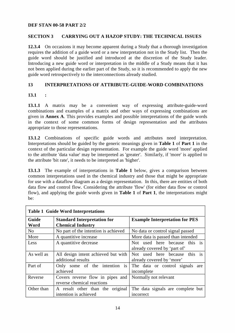
13.1.3 The example of interpretations in Table 1 below, gives a comparison betweencommon interpretations used in the chemical industry and those that might be appropriatefor use with a dataflow diagram as a design representation. In this, there are entities of bothdata flow and control flow. Considering the attribute 'flow' (for either data flow or controlflow), and applying the guide words given in Table 1 of Part 1, the interpretations mightbe:
Table 1 Guide Word Interpretations
GuideWord
Standard Interpretation forChemical Industry
Example Interpretation for PES
No No part of the intention is achieved No data or control signal passedMore A quantitive increase More data is passed than intendedLess A quantitive decrease Not used here because this is
already covered by ‘part of’As well as All design intent achieved but with
additional resultsNot used here because this isalready covered by ‘more’
Part of Only some of the intention isachieved
The data or control signals areincomplete
Reverse Covers reverse flow in pipes andreverse chemical reactions
Normally not relevant
Other than A result other than the originalintention is achieved
The data signals are complete butincorrect

DEF STAN 00-58 PART 2/2
15
SECTION 3 CARRYING OUT A HAZOP STUDY: THE TECHNICAL ISSUES
Table 1 Guide Word Interpretations (Continued)
GuideWord
Standard Interpretation forChemical Industry
Example Interpretation for PES
Early Not used The signal arrives too early withreference to clock time
Late Not used The signal arrives too late withreference to clock time
Before Not used The signal arrives earlier thanintended within a sequence
After Not used The signal arrives later thanintended within a sequence
13.1.4 As the example of the guide word 'reverse' shows (in Table 1, above), there will besome of the generic guide words which do not have a meaningful interpretation for aparticular attribute. There may be others, however, that need more than one interpretation.
13.1.5 For the attribute 'value' for a single data entity, guide words that are consideredrelevant are 'more' and 'less'. Their interpretations are as in Table 2.
Table 2 Guide Word Interpretations for ‘value’
Guide Word Example InterpretationMore The data value is too highLess The data value is too low
13.1.6 See examples in Annex A.

DEF STAN 00-58 PART 2/2
16
SECTION 4 CARRYING OUT A HAZOP STUDY: THE CONTROL ISSUES
14 ROLES OF TEAM MEMBERS
14.1 A HAZOP Study is a creative process. It is key to the success of a Study that theteam dynamics work, and the role of the Study leader is important to enable creativeexploration of deviations.
14.2 Processes and Skills
14.2.1 For each consideration of an attribute-guide-word interpretation, there is a processof:
a. postulation of a possible deviation from design intent;b. exploration of how it could occur and what its possible causes and
consequences might be;c. explanation of the protection and alarm mechanisms in place or planned, of
the behaviour of the system, of problems known with similar systems, and ofother relevant factors;
d. drawing conclusions about whether a hazard exists;e. recording the results.
14.2.2 Each stage of the process requires a particular skill, and there need to be teammembers with the appropriate skills. Two or more roles may be combined in one person,particularly on simple systems. However, it is not recommended that the HAZOP Studyleader role be combined with that of recorder.
14.2.3 The typical roles of the team members in carrying out the process are summarizedin Table 3. However, it is more important that there is a team member capable of carryingout each role of the process than that each role should be the responsibility of a particularteam member.
Table 3 Roles of HAZOP Study Team Members
Postulate Explore Explain Conclude RecordLeader Yes Possibly Possibly YesExpert Yes YesDesigner Possibly YesUser Possibly YesRecorder Possibly Yes
14.3 Role of the Study Leader
14.3.1 In planning a HAZOP Study, the Study leader should attend to practicalarrangements such as agreeing the details of the Study with the Study team and securingaccommodation for the full schedule of Study Meetings.

DEF STAN 00-58 PART 2/2
17
SECTION 4 CARRYING OUT A HAZOP STUDY: THE CONTROL ISSUES
14.3.2 In conducting the HAZOP Study Meetings, the Study leader should ensure that:
a. team members are informed of the Meeting conventions;b. meetings are controlled according to the agreed Meeting conventions;c. the technical aspects of the Study are carried out thoroughly. This includes:
1. covering the system systematically;2. clearly stating the attribute, guide word and interpretation being
considered at any time;3. controlling the Study to ensure that it remains focused on the matter in
hand;4. summarising the conclusions on each item for the recorder.
d. effort is applied effectively, for instance, by ensuring that team members arenot becoming tired or bored;
e. effort is applied efficiently, for instance, by ensuring that all team membersare contributing to the process;
f. the results are documented;g. the documented results are agreed by the full team, or, if consensus cannot be
achieved, that all sides of a disagreement are recorded;h. the Meeting documentation is signed off;i. there is consistency across the full schedule of Study Meetings;j. the Study documentation is distributed to appropriate persons.
14.3.3 In checking that follow-up work has been done, the Study leader should ensure thatthe results of all questions raised are reported back and raised at a later Study Meeting.
14.3.4 In controlling the Study Meetings, the Study leader:
a. should be able to assist the other team members to understand the designrepresentation, if this becomes necessary;
b. may delegate to the recorder the duty of ensuring that the results of previoushazard analyses on the system being studied are available during the planningof the Study and at the Study Meetings;
c. may delegate to the recorder the duty of finding out about previous hazardanalyses of connected systems and ensuring that the relevant results areavailable both at the planning of the Study and at the Study Meetings.
14.3.5 The Study leader has the authority and the duty to terminate or suspend the StudyMeeting at any time if it becomes unproductive - for example, if it is recognised that thedesign representation has not previously been reviewed, or if the team members or theStudy leader have lost concentration.
14.3.6 The Study leader should exclude any team member from the Meeting, at any time,if the member is obstructive, or is in any way compromising the effectiveness or efficiencyof the Meeting.

DEF STAN 00-58 PART 2/2
18
SECTION 4 CARRYING OUT A HAZOP STUDY: THE CONTROL ISSUES
14.3.7 It is recommended that, in order to minimise the chance of problems occurringduring the planning or execution of a HAZOP Study, an organisation carrying out HAZOPStudies should have a standard checklist of the Study leader's functions.
14.4 Role of the Recorder
14.4.1 The responsibilities of the recorder are to:
a. be familiar with the HAZOP Study process;b. understand the design representation used and have an appreciation of the
application's operating environment;c. at the direction of the Study leader, ensure the availability of data and
subsidiary documentation needed for the HAZOP Study and any results ofprevious hazard analyses on the system being studied or connected systems;
d. understand the nature of the documentation to be prepared, as defined in theobjectives of the Study;
e. follow the discussion and participate in the Study;f. document, in concise prose and in the appropriate style, the hazards
identified, their possible causes and consequences, any recommendationsmade, any action for follow-up work, and any cross-references to otherdocuments.
14.4.2 It is recommended that the recorder creates the Study documentation at theMeeting. It should be recognised that the recorder's role is crucial to the success of theStudy.
14.5 Role of the Designer
14.5.1 Ideally, the designer should come from the system design team. At the StudyMeetings, the designer should be able to answer questions about the design, the designrepresentation, and the design intent.
14.6 Role of the User
14.6.1 The choice of the most appropriate user should be guided by the scope and purposeof the HAZOP Study. This means that in some cases a single person cannot cover thecomplete user's role.
14.6.2 The user may be someone who has used, operated or maintained the system; or, ifthe system is still in development, someone who will use, operate or maintain it and whounderstands and can explain its proposed operational environment and context.
14.6.3 The user's role is to advise on the effects, on system operation, of deviations fromdesign intent, and to help in deciding whether or not there is likely to be a safety issue.
DEF STAN 00-58 PART 2/2
19
SECTION 4 CARRYING OUT A HAZOP STUDY: THE CONTROL ISSUES
14.7 Role of the Expert Members
14.7.1 Expert members need to be capable explorers of cause and effect who possessrelevant operating environment knowledge and expertise.
14.7.2 The key role of an expert member is to explore the postulated deviations fromdesign intent, determining whether a hazard exists and, if it does, what its causes andconsequences are likely to be.
14.7.3 Designers and users can often be good explorers, if they can overcome thetemptation to be defensive about the system..
15 SELECTING THE STUDY TEAM
15.1 Team Selection Criteria
15.1.1 It is the Study leader's responsibility to choose the team membership for eachHAZOP Study, but it may be necessary for the Study initiator to make the necessaryarrangements for the availability of the team members.
15.1.2 The Study leader should determine what expertise is necessary for a successfulStudy and select the expert members accordingly. Typical areas of expertise which may beuseful or necessary are: supplier, applications software developer, operator, maintainer,independent expert. Reviewing the design prior to the Study might be a good way ofdeciding what skills are necessary, especially when knowledge of subsystems is required.
15.1.3 The Study leader should also consider the need to choose members who betweenthem possess the abilities to postulate, explore, explain, conclude, and record.
15.1.4 The viewpoints of designer and user are always required on the Study, althoughdifferent personnel may be needed to represent these viewpoints, depending on theparticular stage of the life cycle at which the Study is carried out.
15.1.5 Expert members must be competent explorers of cause and effect. They should bechosen for their wide experience of systems such as the one being studied and of thefunctions and hazards that may be associated with them.
15.1.6 The role of the recorder is important. It should be given to someone whounderstands the representation and the system under review and who has the capability ofparticipating in the exploration of deviations.
15.1.7 When inviting team members, the Study leader should be specific in naming thepersons required, having taken appropriate advice. Representatives of invited membersshould not be accepted unless it is demonstrated that they can contribute to the Study aseffectively as the invited member.

DEF STAN 00-58 PART 2/2
20
SECTION 4 CARRYING OUT A HAZOP STUDY: THE CONTROL ISSUES
15.2 Team Size
15.2.1 A Study team of five members allows each of the identified roles to be representedseparately, and a team of seven allows for extra expertise where needed without excessivelydecreasing the cost-effectiveness of the Study.
15.2.2 When a number of HAZOP Studies are carried out on different representations orstages of the same system, hazards may be missed if there is a lack of team consistencybetween the various Studies. There therefore needs to be a core team which should includethe leader and one or more experts. The team may grow and shrink as specific designers,users, maintainers or experts are called in to answer given questions or for analysis of givenparts of the design. Once systems are in operation, the role of the maintainer will becomeincreasingly important. Maintainers are likely to be either 'users', who carry out repairs tothe system, or 'designers', who change the design of the system in response to operationalfeedback. There needs to be a balance between allowing change in order to bring in theright expertise, maintaining a core team, and keeping the size of the team to a cost-effectiveand manageable level.
15.3 It is recommended that training for a Study leader should include being a recorderat a number of HAZOP Studies.
16 PREPARATORY WORK
16.1 Preparatory Work on the Representation
16.1.1 The Study leader should ensure that appropriate, reviewed design representationsare available. If significant flaws are discovered in the design or a representation, the StudyMeeting should be postponed until the design representations are of adequate quality.
16.1.2 Preparatory Work on Technical Issues:
a. The Study leader should ensure that the results of previous hazardidentification work are available for the Study and are used to guide thechoice of attributes and the level of detail of the representation;
b. the Study leader should work with the designer to identify and list the entitiesand attributes for components and interconnections in the designrepresentation;
c. the Study leader should choose the guide words and define theirinterpretations for each attribute in the context of the present HAZOP Study,taking advice from designers as appropriate;
d. the Study leader, in the light of experience and the defined scope of theStudy, should assess the adequacy of the attributes and guide words for athorough analysis. If they are inadequate, a further design representationshould be provided.

DEF STAN 00-58 PART 2/2
21
SECTION 4 CARRYING OUT A HAZOP STUDY: THE CONTROL ISSUES
16.1.3 Preparatory Work on Planning the Study:
a. The Study leader should plan the Study (which may comprise a number ofMeetings) in consultation as necessary with the designer and the Studyinitiator;
b. in planning, the question of whether more than one design representation isneeded should be taken into account;
c. it should be decided what level of recording is required - the recording ofeverything which transpires at the Meeting, or only exception reporting; alsowhether what is recorded is a full report of the activities and their results, oronly a summary;
d. it should be decided what rules will apply (for example, see clause 17.1.1 ofPart 2) so as to ensure efficiency and effectiveness of Study Meetings;
e. the availability of all team members should be assured for the full schedule ofStudy Meetings. Substitute members with the appropriate credentials shouldbe identified to cover unexpected absences.
16.2 Briefing the Team
16.2.1 It is recommended that the distribution of a briefing pack should take place at leasttwo weeks prior to the first Study Meeting.
16.2.2 It is recommended that an organisation using HAZOP Studies should design astandard form for the Study leader to use in preparing the plan and issuing a call to the teammembers.
16.3 Room Layout and Facilities
16.3.1 In planning the Study, attention should be paid to the room layout and facilities. Inparticular:
a. the room should have sufficient space for the easy movement of all teammembers;
b. the design representation being examined needs to be in such a position thatall team members are able not only to see it, but also to use it for reference indiscussion;
c. there should be means for public generation of text and diagrams (such as aflip chart or white board) to clarify points or focus discussion.
17 THE CONDUCT OF A HAZOP STUDY MEETING
17.1 Discipline for Maintaining Progress and Achieving Efficiency
17.1.1 The progress of a Study Meeting is impaired by prolonged discussion or argument.The Study leader should therefore enforce the following discipline:
a. discussion should stick to the point;

DEF STAN 00-58 PART 2/2
22
SECTION 4 CARRYING OUT A HAZOP STUDY: THE CONTROL ISSUES
b. discussion should not stray towards the design or redesign of the system: thepurpose of a HAZOP Study is to find hazards and their causes, not to solveproblems;
c. only one person should speak at a time;d. a maximum of 10 minutes should be spent on the discussion of any one point.
After that, a question should be raised and the matter listed for follow-upwork. (Note that it should be rare to spend 10 minutes on a single point.);
e. the Study leader should stop the Meeting, or call a break, if it has becomeineffective, for example, through people becoming tired or bored or if therepresentation being studied is revealing no new hazards.
17.1.2 Because the success of HAZOP Study Meetings depends on alertness andconcentration, the following discipline should apply:
a. there should be a time limit of three hours on a Study Meeting, but Meetingsof two hours may prove more effective;
b. there should be a break of about five minutes at the end of each hour, and thetime of this break will need to be controlled by the Study leader;
c. there should be a maximum of two Study Meetings in a day;d. two Meetings in the same day should be separated by at least one and a half
hours;e. two Meetings per day should be held for a maximum of three consecutive
days, after which there should be a break of at least two days.
17.2 The Study Process
17.2.1 Initial Activities:
a. At the start of a HAZOP Study Meeting, the Study leader should:1. conduct introductions of all the team members and ensure that their
names are recorded;2. briefly review the Study plan to ensure that all team members are
familiar with the system and its background, with the nature of aHAZOP Study, with the relevant technical issues, and with the conductof the particular Meeting.
b. Additional tasks which the Study leader should perform at the start of aHAZOP Study Meeting are to review the technical and recording issues:1. describe the conventions used on the design representations and ensure
that team members have a common understanding of them;2. briefly describe the attributes on the design representation, the guide
words to be used, and the attribute-guide-word interpretations to beapplied;
3. define whether recording will be done in total or by exception.

DEF STAN 00-58 PART 2/2
23
SECTION 4 CARRYING OUT A HAZOP STUDY: THE CONTROL ISSUES
c. When the Study team is unfamiliar with carrying out a HAZOP Study on thetype of design representation being studied, it is recommended that a brieftraining HAZOP Study be carried out on a simple but complete example ofthat type of design representation.
d. Having set the scene for the Study Meeting, the Study leader should ask thedesigner to give an overview of the design, its context, and its intent.
17.2.2 Progress of the Study Meeting
a. The hazard identification process derives its power from a step-by-stepprocedure.
b. It is suggested that the analysis proceeds forward from inputs to outputs,choosing interconnections in a logical sequence.
c. One form of marking which has been found useful is to trace over thecomponent or interconnection with a highlighting pen of one colour when itis chosen and to go over it again with one of a different colour when its studyhas been completed. Alternatively, on-line support for the representationmay be helpful here and during the subsequent steps of the Study. Displayshould be visible to all team members.
d. When more than one representation is being used, it may be efficient to studya given component or interconnection on all of them at the same time.
e. From the list of entities (there may only be one) on a component orinterconnection, the Study leader chooses one and marks it as being understudy. Then the Study leader chooses one of the attributes of that entity andmarks it. The Study leader next identifies which guide word is to be appliedand identifies the applicable attribute-guide-word interpretations.
f. Using an attribute-guide-word interpretation as a prompt, the Study teamleader postulates a deviation. This is then explored by the team, usually bythe expert team members and possibly by the Study leader, the designer orthe user. If it is considered a credible deviation, its causes and consequencesare explored, usually by the designer, the user or an expert member.
g. If the Study leader considers that an identified hazard would be betteraddressed under a different guide word, the team leader should note this inwriting and ensure that it is covered when the appropriate guide word israised.
h. The Study team should identify those elements of the system which help toprevent, detect, or give an indication of the hazard.
i. The Study leader may choose to make notes of the summary on the displayeddesign representation, thus facilitating subsequent comparison and discussionwith the recorder.
j. The Study leader then either proposes a recommendation or raises a questionto be answered outside the Meeting. The Study leader may invite the team topropose the recommendation or question, and this is refined until consensusis reached and it is documented.

DEF STAN 00-58 PART 2/2
24
SECTION 4 CARRYING OUT A HAZOP STUDY: THE CONTROL ISSUES
k. In exceptional circumstances, consensus may be impossible to achieve. Insuch a case, the Study leader should direct the recorder to document thevarious opinions, raise a question or recommendation, and then proceed withthe Study.
l. It should be noted that it is not unusual for the first day (one or two StudyMeetings) of a HAZOP Study with a new team to proceed slowly. Efficiencyimproves as the team members come to understand the process and eachother, and learn to minimise extraneous discussion.
17.2.3 The first applicable attribute-guide-word interpretation is then applied in order tosee if there is a credible deviation of the attribute from the design intent. If a credibledeviation is identified, it is examined for possible causes and consequences.
17.2.4 Any previous hazard identification studies should be made use of at this stage.
17.2.5 The presence of protection or indication mechanisms must not stop identifiedhazards being explored and listed. If such mechanisms exist, the team may explore theirefficacy in reducing the probability or mitigating the consequences of the hazard, if this isappropriate. The conclusion or recommendation shall be noted in the HAZOP Studydocumentation.
17.2.6 Risk assessment of the hazards identified should not be carried out during theHAZOP Study, but as a separate activity as specified in DEF STAN 00-56.
17.2.7 The Study leader concludes the examination of the chosen attribute-guide-wordinterpretation by summarising the results, which are documented by the recorder.
17.2.8 The process is then repeated for all the attribute-guide-word interpretations for thatguide word; then for each other guide word; then for each other attribute of the entity understudy. Finally, each other entity on that component or interconnection is treated in the sameway. Then the component or interconnection is marked as having been studied and theStudy leader chooses another on which to repeat the whole process (see Fig 2).
17.3 HAZOP Study Process
17.3.1 A HAZOP Study should not be used as a design review. If the design or the designrepresentation is inadequate or incorrect, the Study may be compromised. The success of aHAZOP Study depends on a thorough design review having previously been carried out.
17.4 Team Dynamics
17.4.1 A HAZOP Study is only as good as the team taking part. Like most team activities,the personal knowledge and skills of the team members are important to success. The waythe team members work together is crucial. One of the advantages of the process is that theteam can build on a comment by one team member and explore unusual interactions. AHAZOP Study is therefore a creative activity. In order for this creative resonance to beachieved, the Study leader's control and leadership is vital.

DEF STAN 00-58 PART 2/2
25
SECTION 4 CARRYING OUT A HAZOP STUDY: THE CONTROL ISSUES
17.4.2 It is often useful for learners of the HAZOP Study process to attend HAZOPmeetings as silent observers. Experiencing the creative interaction of the team is anexcellent way to reinforce information received in formal training.
17.5 Study Examples
17.5.1 Annex B gives an example of a HAZOP Study of a simple high-level systemdesign. Annex C and Annex D give examples of two small, but real, HAZOP Studies ofsoftware designs.
18 RECORDING THE RESULTS OF THE STUDY
18.1 Recording Style
18.1.1 The full recording style is to record every transaction during the Study - that is tosay, the results of applying every attribute-guide-word combination to all the variouscomponents and interconnections on the design representation. This style provides thebasis of proof that a HAZOP Study has been thorough. If done well, it is likely to satisfymost audit requirements.
18.1.2 The alternative style is to record by exception only, which implies recording onlythe discovered hazards and their causes, and the actions for follow-up work. This results inmore easily manageable documentation, and it does not necessarily diminish the value ofthe Study. However, it does not demonstrate the thoroughness of the Study and is thereforeless useful for audit purposes or for future proof of what was done. It should therefore beused with care.
18.1.3 In setting the objectives for a HAZOP Study, the Study initiator should decidewhich style is to be used. Examples of factors which are relevant to this decision are:
a. relevant corporate policy;b. regulatory requirements which might apply (the Study initiator should
therefore be aware of the relevant regulations in force);c. contractual obligations;d. the likely auditing requirements;e. the possible future need for proof of what was done in the Study;f. the magnitude of risks from the system.
18.2 Study Output
18.2.1 At each Study Meeting, the Study leader should ensure that the necessarydocumentation is produced by selecting a capable recorder, briefing the recorder before theStudy, ensuring the recorder's familiarisation with any software package which is to be usedfor recording or display, and checking the work of the recorder from time to time during theMeeting.

DEF STAN 00-58 PART 2/2
26
SECTION 4 CARRYING OUT A HAZOP STUDY: THE CONTROL ISSUES
18.2.2 The Study leader, working with the recorder, should decide on the most appropriatemethod of recording. This will reflect personal experience as well as any organisationguidelines that may be in place.
18.3 Recorded Information
18.3.1 There are instances when it is not clear whether a hazard could occur, for examplewhen the designer is unsure about certain aspects of the design. Then the Study cannoteither dismiss the possibility of a hazard or conclude with a recommendation, so it may beappropriate to raise a question. As a HAZOP Study should not end on a question, the issueshould be studied subsequent to the Meeting at which it is raised. The Study leader shouldreview the results given as replies to questions and decide whether the question may beclosed, a recommendation raised, or the results presented at a future Meeting.
18.3.2 The following apply to recorded information:
a. when protection or alarm mechanisms exist in the system, there may be arecommendation for further work to explore their efficacy in the light of thehazards found. The hazard is recorded notwithstanding the protection oralarm mechanism;
b. every question raised for study after the Meeting by the team should berecorded, with the individual responsible for carrying out the work beingidentified, as well as the date of completion;
c. unique and exhaustive numbering of all Study result items allows latertraceability of items in audits, in the hazard log, and when follow-up work ischecked;
d. it is recommended that an organization carrying out HAZOP Studies shouldhave a standard form on which to record results.
18.4 All identified hazards should be recorded in the hazard log. Whereas it isimportant to have a defined documentation method within the Study, all safety-relatedsystems should have associated with them a mandated method of recording all identifiedhazards.
18.5 Documentation Review
18.5.1 Some HAZOP Study practitioners have found it an advantage if the recorder is acompetent typist and inputs the Study documentation to an electronic medium during theStudy Meeting. There now exist software packages and other tools for immediate recordingand display. These may be considered for use in HAZOP Studies because the signing off ofthe recorded information requires the agreement of all team members present. If they canread the documentation and agree it before the end of each Meeting, time and effort aresaved.
18.5.2 The following are examples of the way in which the Meeting documentation maybe prepared and presented to the Study team for its agreement:

DEF STAN 00-58 PART 2/2
27
SECTION 4 CARRYING OUT A HAZOP STUDY: THE CONTROL ISSUES
a. having recorded the information on paper, the recorder reads it out, sheet bysheet, to the team at the end of the Meeting;
b. if the information is being recorded on an electronic medium, it may beprojected onto a screen throughout the meeting. This can achieve immediateagreement, but it often gives rise to trivial editing which is time-consuming.The Study leader needs to ensure that time is used effectively;
c. having recorded the information onto an electronic medium during theMeeting, the recorder projects it onto a screen at the end of the Meeting.With a good recorder this method saves a great deal of time;
d. the Study leader checks and edits the documentation overnight and presents itto the Study team at the beginning of the next day's Meeting. This methodmay also require an additional Meeting arranged only for achievingagreement to the documentation of the final Study Meeting. (The Studyleader needs to remain alert during Meetings so should not use the breakbetween two Meetings on the same day for the checking of documentation.).
18.5.3 It is preferable to obtain the agreement of the Study team to the Meetingdocumentation before the team disperses at the end of a Meeting.
18.5.4 The Study documentation should be stored permanently and referenced by thehazard log.
18.5.5 An electronic medium may be used both for the initial recording of the informationand for obtaining agreement on the documentation, but signing-off by the Study leader willnormally require a print out of all sheets.
18.5.6 When consensus has been impossible to achieve (see 17.2.2 k. in Part 2) thevarious opinions should be recorded.
19 FOLLOW-UP WORK
19.1 Follow-up Meeting
19.1.1 The Study leader may need to arrange a follow-up Meeting of the Study team tocontinue the Study in the light of the feedback from the follow-up work. At this Meeting,the same responsibilities and rules apply as at the Study Meetings in the original schedule.
19.1.2 As answers are often found between Study Meetings, and thus taken intoconsideration during the original scheduled Meetings in the Study, the outstandingquestions should be reviewed by the Study leader at the end of the original schedule ofStudy Meetings to assess the need for a follow-up Meeting to complete the Study. Asdescribed in 18.3.1 of Part 2, the Study leader may close questions between Meetings.

DEF STAN 00-58 PART 2/2
28
SECTION 4 CARRYING OUT A HAZOP STUDY: THE CONTROL ISSUES
19.2 It is not usual for the Study leader to have the direct authority to ensure that theStudy team's recommendations are acted on, and the help of the Study initiator may beneeded (see 8.2 in Part 2). However, the system safety certification will make use of theHAZOP report thus giving 'authority' to the Study leader by implication. In addition, allhazards identified in the Study will be entered into the system Hazard Log and theprocedure called for in DEF STAN 00-56 will help ensure that recommendations are actedon.
20 AUDITING
20.1 Auditing Criteria
20.1.1 Having an independent safety auditor (ISA) to observe and audit some HAZOPStudies should be considered. This provides not only independence of the audit but alsoencouragement to the Study leader to ensure an auditable Study.
20.1.2 In laying down criteria against which to audit a HAZOP Study and its results, thefollowing are relevant:
a. personnel issues:1. do adequate procedures exist for carrying out HAZOP Studies?2. were there suitable team members at the Study to support the defined
team roles?3. were the appropriate team members (with the right knowledge) chosen?4. was the leader trained?5. was the preparatory work carried out thoroughly?
b. were there adequate procedures in place to ensure that:1. all attributes were identified?2. all relevant guide words were applied to all attributes?3. the Study was carried out in a technically appropriate manner?
c. documentation and follow-up issues:1. was a Study plan distributed to the Study team in advance of the Study?2. was the design representation verified before use in the Study?3. was recording carried out in accordance with the instructions?4. were all hazards, questions and recommendations clearly labelled and
numbered?5. was every sheet of results signed off by the Study leader?6. were the results of all questions for Study by the Study team fed back to
a Meeting of the team?7. was a follow-up Meeting held?
20.2 The above are examples only and do not comprise an exhaustive checklist for theauditing of the Study process. Thorough checks of the technical aspects of the Study arerecommended.
20.3 No further guidance.

DEF STAN 00-58 PART 2/2
29
ANNEX A
ANNEX A
EXAMPLE GUIDE WORD INTERPRETATIONS
A.1 INTRODUCTION
A.1.1 This Annex gives example interpretations of the HAZOP Study guide words in thecontext of the attributes arising from the application of HAZOP Studies.
A.1.2 Where considered necessary to explain the context for the choice of guide wordand interpretation, the notation for the design representation is also described.
A.1.3 In the context of this Annex, design is used as a generic term to cover thedevelopment process. In particular, it is possible, and often appropriate, to use a HAZOPStudy to identify hazards at the requirements capture stage of a project.
A.1.4 Guide word interpretations are given for the software design representations of dataflow diagrams, state transition diagrams and object oriented design. Suggested attributesand guide word interpretations for electronic hardware, communication networks andelectromechanical systems are included. Also given are some considerations for the choiceof attributes and the interpretation of guide words when timing information is available.
A.1.5 Interpretations of guide words should be made in the context of the system beingstudied and its representation. It is important that the set of attributes, guide words andinterpretations is understood by the team using it, applied consistently, and sufficient toexplore plausible deviations from design intent.
A.1.6 The set of guide words and interpretations given in this Annex are examples whichhave been found to work on particular HAZOP Studies. Other guide words andinterpretations are not precluded and, in fact, may be more appropriate for particularstudies. This is an important point. The purpose of the guide word is to facilitate thecreative exploration of deviations by a team.
A.1.7 In clauses A.2 to A.5 , the attributes, guide words and interpretations are given intables. In the later sections, they are given as matrices. Individual organisations shouldchoose an appropriate and convenient method.
A.1.8 For ease of reference the set of guide words given in clause 12 of Part 1 is repeatedhere. The generic list of guide words is:
No: This is the complete negation of the design intention. No part of theintention is achieved and nothing else happens.
More: This is a quantitative increase.
Less: This is a quantitative decrease.

DEF STAN 00-58 PART 2/2
30
ANNEX A
As well as: All the design intention is achieved together with additions.
Part of: Only some of the design intention is achieved.
Reverse: The logical opposite of the intention.
Other than: Complete substitution, where no part of the original intention is achievedbut something quite different happens.
Early: Something happens earlier than expected relative to clock time.
Late: Something happens later than expected relative to clock time.
Before: Something happens before it is expected, relating to order or sequence.
After: Something happens after it is expected, relating to order or sequence.
A.2 GUIDE WORD INTERPRETATIONS FOR DATA FLOW/CONTROLFLOW DIAGRAMS
A.2.1 Data flow diagrams are well established and have been found easy to understand bythose who are not familiar with software design techniques. The diagram given below is acommon convention, using a sub-set of the Hatley-Pirbhai methodology [1], modified toshow the entities of data flows and control flows on the same diagram, rather than onseparate ones.
DATA STORE Name 1
Fig 1 Data Flow/Control Flow Diagram
1
ProcessName 1
2
ProcessName 2
Data flow 1
Control flow 1
Data flow 2 Data flow 3

DEF STAN 00-58 PART 2/2
31
ANNEX A
A.2.2 A design using data flow diagrams will usually be presented in a hierarchicalmanner with high-level processes being decomposed into lower-level processes, withassociated greater levels of detail for some of the data flows. Thus a HAZOP Study oflower levels of a design will, in fact, begin to ‘look inside’ the processes defined at thehigher level.
A.2.3 It is convenient to think of data flows as being intermittent or continuous. Controlflows are data flows with a control context and are modelled as separate entities in manymethodologies. Because of their context, in the Hatley-Pirbhai methodology they arealways intermittent flows. During a HAZOP Study it may be useful to distinguish betweenthese different types when examining credible deviations.
A.2.4 Data flows may be anything from a single item, to a group of any number of items.The name at a group level is usually descriptive of that whole group. Group flowsdecompose into sub-group flows and eventually into primitive, single-item flows: thisdecomposition often happens as the group passes from a parent to a child diagram. Withgroup flows, there may be a need, sometime during the HAZOP Study, to look at theprimitive flows. This may be when the decomposition reaches a level at which theprimitive flows become apparent, or earlier at the discretion of the HAZOP Study leader.For example, if the exploration of deviations of group flows leads to discussion of theprimitive flows, this may indicate a need to look at the primitive flows rather than the groupflows.
A.2.4 When a group flow splits between processes, such that one part of the group goesto one receiving process and the remainder to another receiving process, the HAZOP Studyshould address them as separate data flows between the sending process and the tworeceiving processes. Similarly, a two-way flow between processes should be addressed asflows in each direction.
A.2.6 Table 4 gives the attributes that might be explored for deviations as well as somepossible interpretations for the guide words associated with those attributes. Note that formany of the attributes, only a few of the standard guide words are considered to havemeaningful interpretations. Also note that the table is applicable to generic data flows. It ispossible to derive more detailed interpretations for particular data types.

DEF STAN 00-58 PART 2/2
32
ANNEX A
Table 4 Example Attribute-Guide-Word Interpretations for Data Flow Diagrams
Attribute Guide Word InterpretationFlow (of data or control) No No information flow.
More More data is passed than expected.Part of The information is passed incomplete
(for group flows).Reverse Flow of information in wrong
direction (normally not credible).Other than Information complete, but incorrect.Early Flow of information occurs before it
was intended.Late Flow of information occurs after it
was required.Data rate More The data rate is too high.
Less The data rate is too low.Data value More The data value is too high (within or
out of bounds).Less The data value is too low (within or
out of bounds).
A.3 GUIDE WORD INTERPRETATIONS FOR STATE TRANSITIONDIAGRAMS
A.3.1 Finite state machines [1] recognize that many processes may be in a number ofstates (an aircraft, say, could be in the states of ‘stationary’, 'taxi-ing', 'taking-off' , 'in-flight'or 'landing'). Finite state machines (often using state transition diagrams) give the 'rules' forhow transitions between states occur. In any given ‘state’, when an ‘event’ occurs that isassociated with a transition from that state, the machine will go to the state indicated by thattransition and will perform the associated 'action'. With the Mealy model [1] for statetransition diagrams, the actions are associated with the transition and so are convenient forexploration using a HAZOP Study.
A.3.2 Fig 2 shows a typical convention for a state transition diagram (taken from Hatley-Pirbhai). 'States' are shown as rectangular boxes containing the state names. 'Transitionarcs' are lines with arrowheads showing the directions of the transitions. 'Events' are theinitiating conditions for transitions shown by name as labels on the arcs of the transitionsthey cause. 'Actions' are shown by name, adjacent to the events that cause them with thetwo separated by a line e.g. event/action. One event is shown as the start state.
A.3.3 Table 5 shows example interpretations for state transition diagrams, using the twoattributes of event and action. If additional information on timing issues is available, thendeviations may be explored as in A.4 of this Annex.

DEF STAN 00-58 PART 2/2
33
ANNEX A
STATE 1
Event/Action
STATE 2
Fig 2 The Convention for State Transition Diagrams
Table 5 Example Attribute-Guide-Word Interpretations for State TransitionDiagrams
Attribute Guide Word InterpretationEvent No Event does not happen.
As well as Another event takes place as well.Other than An unexpected event occurs instead
of the anticipated event.Action No No action takes place.
As well as Additional (unwanted) actions takeplace.
Part of An incomplete action is performed.Other than An incorrect action takes place.
A.4 GUIDE WORD INTERPRETATIONS FOR TIMING INFORMATION
A.4.1 Timing of Events and Actions
A.4.1.1 When timing information is available together with the state transition diagramthen the additional attribute of timing may be associated with the attributes of event andaction, giving rise to the possible interpretations in Table 6.

DEF STAN 00-58 PART 2/2
34
ANNEX A
Table 6 Example Attribute-Guide-Word Interpretations for Timing
Attribute Guide Word InterpretationTiming of Event or Action No Event/action never takes place.
Early Event/action takes place before it isexpected.
Late Event/action takes place after it isexpected.
Before Happens before another event oraction that is expected to precede it.
After Happens after another event or actionthat is expected to come after it.
A.4.2 Repetition and Response Time
A.4.2.1 Timing issues in many designs are given in terms of the attributes of repetitiontime and response time. Repetition time is the time between successive updates of externalprimitive outputs. Response time is the time from input to output. An example of repetitiontime is the need to update commands to the control surfaces of an aircraft every 100 msecs.An example of response time is the time to initiate closure of a valve after an operatorpresses a close switch. Table 7 below gives example interpretations for relevant guidewords for the two attributes.
Table 7 Example Attribute-Guide-Word Interpretations for Repetition andResponse Time
Attribute Guide Word InterpretationRepetition time No Output is not updated.
More Time between outputs is longer thanrequired.
Less Time between outputs is shorter thanrequired.
Other than Time between outputs is variable.Response time No Never happens (time is infinite).
More Time is longer than required.Less Time is shorter than required.Other than Time is variable.
A.5 GUIDE WORD INTERPRETATIONS FOR OBJECT ORIENTED DESIGNS
A.5.1 The use of object oriented design methods has increased rapidly in recent years.There are many different notations and approaches used: in this section the notationproposed by Shlaer-Mellor [2] is used. A complete design using the Shlaer-Mellorapproach comprises four basic models:
DEF STAN 00-58 PART 2/2
35
ANNEX A
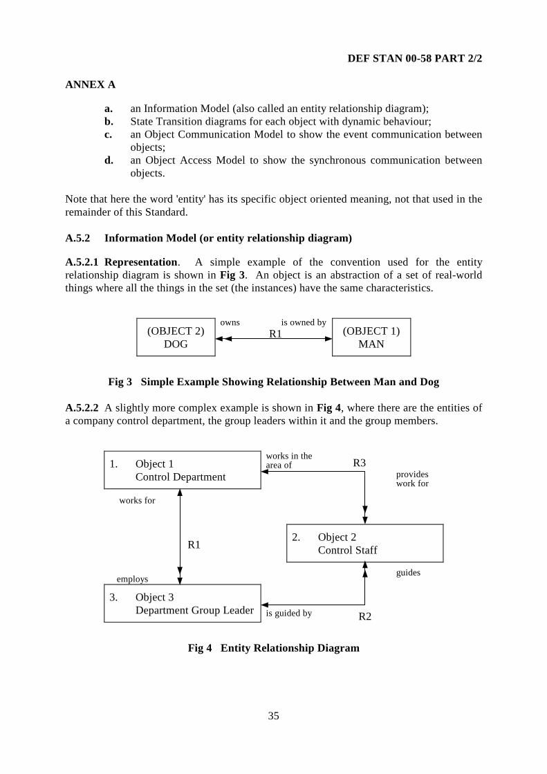
a. an Information Model (also called an entity relationship diagram);b. State Transition diagrams for each object with dynamic behaviour;c. an Object Communication Model to show the event communication between
objects;d. an Object Access Model to show the synchronous communication between
objects.
Note that here the word 'entity' has its specific object oriented meaning, not that used in theremainder of this Standard.
A.5.2 Information Model (or entity relationship diagram)
A.5.2.1 Representation. A simple example of the convention used for the entityrelationship diagram is shown in Fig 3. An object is an abstraction of a set of real-worldthings where all the things in the set (the instances) have the same characteristics.
(OBJECT 2)DOG
owns is owned by R1 (OBJECT 1)
MAN
Fig 3 Simple Example Showing Relationship Between Man and Dog
A.5.2.2 A slightly more complex example is shown in Fig 4, where there are the entities ofa company control department, the group leaders within it and the group members.
1. Object 1Control Department
works in thearea of
provideswork for
works for
R12. Object 2
Control Staff
employsguides
3. Object 3Department Group Leader is guided by
Fig 4 Entity Relationship Diagram
R3
R2

DEF STAN 00-58 PART 2/2
36
ANNEX A
A.5.2.3 From the point of view of a HAZOP Study relationships are what can causedeviations. Relationships are unconditional where every instance of an object is required toparticipate in the relationship as in the examples below. In a conditional relationship, thereare instances of objects that do not participate. Relationships may be of the followingforms:
a. one-to-one, where a single instance of an object is associated with a singleinstance of another (e.g. husband and wife);
b. one-to-many, where a single instance of an object is associated with one ormore instance of another, and each instance of the second is associated withjust one instance of the first (e.g. the man and dog relationship of Fig 3);
c. many-to-many, where a single instance of an object is associated with one ormore instances of another and each instance of the second object is associatedwith one or more instances of the first (e.g. house and owner).
A.5.2.4 Interpretation of Guide Words Possible guide word interpretations for theattribute of relationship are shown in Table 8. Note that here there are two differentinterpretations for two of the guide words.
Table 8 Example Attribute-Guide-Word Interpretations for Entity Relationships
Attribute Guide Word InterpretationRelationship No Relationship does not take place.
More/less Wrong cardinality in a relationship(for example it is one-to-one insteadof one-to-many).
Part of (i) The set of relationships held by anentity shows incompatibilitiesbetween individual relationships.
Part of (ii) There is a required relationship that isnot shown on the design.
Other than (i) The wrong relationship is definedbetween objects (i.e. there should bea relationship between the objects butnot the one given).
Other than (ii) Relationship is wrong (i.e. thereshould not be a relationship betweenthe objects even though one is given).
A.5.3 STATE TRANSITION DIAGRAMS.
A.5.3.1 The Shlaer-Mellor approach uses the Moore state model [2] (as opposed to theMealy one used in A.3 above). The main difference from Mealy is that the actions areaccomplished when an instance arrives in a state, rather than being associated with thetransition between states.

DEF STAN 00-58 PART 2/2
37
ANNEX A
A.5.3.2 From a purist point of view, in this case the actions are 'hidden’ in the states and soa HAZOP Study might not consider them if it is concentrating on the interactions.However, in practice, a HAZOP Study would be likely to explore deviations of the actionsas well as the events.
A.5.3.3 Exploring deviations may be addressed as described in A.3 above (and A.4 ifadditional information on timing is available).
A.5.4 Object Communication Model
A.5.4.1 When a state model generates an event, the target state model receives the eventsome time after the action in which the event was generated is complete. The objectcommunication model gives a summary of such event communication between state modelsand external entities, i.e., the asynchronous communication between state models in thesystem. Each state model is represented by an oval labelled with the name of the statemodel. Each external entity (such as switches or actuators) that can generate or receiveevents is depicted by a box.
EXTERNALENTITY 1
EXTERNALENTITY 2
EXTERNALENTITY 3
Fig 5 Example Object Communication Model
STATE MODEL 1
STATE MODEL 2 STATE MODEL 3

DEF STAN 00-58 PART 2/2
38
ANNEX A
A.5.4.2 An event that is generated by one state model or external entity and received byanother is shown by an arrow from the generating component to the receiver, annotated withthe event label, meaning and (optionally) event data. An example is given in Fig 5.
A.5.4.3 The object communication model has the attribute of 'event' that can be addressedduring a HAZOP Study. Exploring deviations of events may be addressed as described inA.3 above (and A.4 if additional information on timing is available).
A.5.5 Object Access Model
A.5.5.1 The object access model gives a summary of the synchronous communicationbetween state models and data of object instances. When a state model accesses the data ofan instance of another object through an accessor process, the data access takes place duringthe time that the action is running. An object is represented by a flattened oval labelledwith the name of the object. The oval represents both the data describing the instances ofthe object and the state model.
A.5.5.2 If a state model (say state model A) makes use of an accessor assigned to anotherobject (object B), an arrow is drawn from object A to object B, labelled with the processidentifier of the accessor as shown in Fig 6. The diagram provides a summary of thesynchronous communications between state models and object instance data.
Fig 6 Example Object Access Model
A.5.5.3 A HAZOP Study of this model can treat each interaction as a data flow, with thesame set of potential deviations as described in A.2 above.
A.6 GUIDE WORD INTERPRETATIONS FOR COMMUNICATION SYSTEMS
A.6.1 In looking at a communications network or a specific communications link, thereare attributes to examine such as the topology of the network, the encoding of the data andthe data rate.
STATE MODEL BCooking Items
STATE MODEL COven
STATE MODEL AOven Automatic Controls
B1
C1C2
Find correct oven for item
Find temperature of ovenFind heater of oven

DEF STAN 00-58 PART 2/2
39
ANNEX A
A.6.2 Table 9 shows a matrix of attributes and guide word interpretations appropriate foruse in a HAZOP Study of the communications of a system.
A.6.3 The matrix has the standard guide words as the headings for each column, theattributes being examined at the left hand of each row, and the interpretations filling eachelement.
A.6.4 A communication system has a topology, that is the connectivity between a set ofnodes, and also encompasses whether a node is a transmitter, a receiver or both. Thistopology may range from static, through dynamic due to failure, to fully dynamic wherenodes can be freely connected or disconnected. The communication system will have oneor more masters which control activity on the network. The other masters may be present toincrease reliability by redundancy or the system may support multi-masters, e.g. Ethernet.
A.6.5 The data transferred will be encoded to improve the reliability of the system byproviding error detection or error correction capability. The protocol defines how the datais transferred between nodes, for example, whether transmission starts following a requestfrom another node, or from an internal event. The system has a bandwidth or data capacitywhich at a simple level will affect response time, which will in turn vary according to themessage priority.
A.6.6 Whether the communication system is synchronous (locked to a central clock) orasynchronous, the data rate is a key attribute.
A.7 GUIDE WORD INTERPRETATIONS FOR DIGITAL ELECTRONICHARDWARE
A.7.1 In carrying out a HAZOP Study on a representation of the design of digitalelectronics there is a need to define appropriate attributes and interpretations of the guidewords. Taking a simple example of an electrical connection between two component partsof an electrical design, a matrix of possible attributes and interpretations is shown inTable 10.
A.7.2 In this example there are two parts of an electrical design. These parts may bediscrete components or complex digital systems.
A.7.3 The first attribute is the relationship between the ground (0V) potentials of the twoparts. On a printed circuit board with a ground plane this is not an issue. However, itbecomes important in systems, for example, with separate ground regimes, large physicalseparation or high data rates.
A.7.4 The connection between these parts gives the remainder of the attributes. Thephysical connection attribute looks at the number of connections, the possibility of wrongconnection and the likelihood and effects of crosstalk and shorting between carriers.

DEF STAN 00-58 PART 2/2
40
ANNEX A
A.7.5 The voltage and current attributes compare the drive capability of one end, with theloading and impact requirements of the other. The protocol attributes cover which end maydrive the link for bi-directional signals, and how the signal is transferred relative to a timingreference. Finally, the capability of the carrier is questioned.
A.8 GUIDE WORD INTERPRETATIONS FOR ELECTRO-MECHANICALSYSTEMS
A.8.1 Frequently, PES are included in systems together with electro-mechanical parts anda HAZOP Study will need to address those aspects. A typical mechanical sub-system mightinclude components such as motors, shafts and gearboxes. In Table 11 some sampleattributes are given for the mechanical parts of such a system, together with exampleinterpretations of guide-words to explore deviations.
References:
[1] Hatley D and Pirbhai I. Strategies for real-time system specification.Dorset House, 1988. ISBN 0-932633-11-0
[2] Shlaer S and Mellor S. Object lifecycles: Modelling the world in states.Yourdon Press, 1992. ISBN 0-13-629940-7

Table 9 Matrix of Example Attributes and Guide Word Interpretations for a Communication System
NO MORE LESS AS WELL AS PART OF REVERSE OTHER THAN EARLY LATE BEFORE AFTER
GenericMeanings
No part of theintention isachieved.
A quantitiveincrease.
A quantitivedecrease.
All designintent but withadditionalresults.
Only some ofthe intentionis achieved.
The logicalopposite ofthe intention.
Result otherthan originalintention isachieved.
Relative toclock time.
Relative toclock time.
Relative toorder orsequence.
Relative toorder orsequence.
PhysicalTopology
N/A There aremore nodesthan required.
There are fewernodes thananticipated orrequired.
N/A Ability totransmit orreceive butnot both, e.g.duplexbecomessimplex.
N/A Rogue nodemisbehaving_____________
Wrongarchitecture
N/A N/A N/A N/A
MasterNo masternode isidentified
More activemasters thanplanned.
Less mastersactive thanplanned.
N/A N/A N/A Master is otherthan the oneexpected to be incontrol.
N/A N/A N/A N/A
Encoding forReliability
Encodingmissing.
Greaterreliability atbandwidth.
Less reliabilitythan required.
N/A N/A N/A Corruption ofthe encoding.
N/A N/A N/A N/A
Protocol
No protocolimplemented.
N/A N/A Otherhandshakes orother controlsignals.
Partialcommand orresponse.
Transmitswhen shouldbe receivingor vice versa.
Protocol signalspresent butwrong.
Relative toclock time.
Relative toclock time.
Relative toorder orsequence.
Relative toorder orsequence.
Bandwidthof Signals
N/A More thanexpected(slower or noresponse).
Less data thanexpected (fasterresponse).
N/A N/A N/A N/A N/A N/A N/A N/A
Data rate
No data istransferred.
Data rate istoo high.
Data rate is toolow.
Inappropriateloading of asharedchannel.
N/A N/A Variable N/A N/A N/A N/A

Table 10 Matrix of Example Attributes and Guide Word Interpretations for Digital Hardware
NO MORE LESS AS WELL AS PART OF REVERSE OTHER THAN EARLY LATE BEFORE AFTER
GenericMeanings
No part of theintention isachieved.
A quantitiveincrease.
A quantitivedecrease.
All designintent but withadditionalresults.
Only some ofthe intentionis achieved.
The logicalopposite ofthe intention.
Result otherthan originalintention isachieved.
Relative toclock time.
Relative toclock time.
Relative toorder orsequence.
Relative toorder orsequence.
VoltageDifferenceBetweenGrounds
Undefined. Too high adifference.
N/A N/A N/A N/A Grounds thoughtto be static thatare moving.
N/A N/A N/A N/A
NumberofConnections
Missing orbrokenconnection.
N/A Lessconnectionsthan signalsneeded.
Crosstalk. N/A Twisted buse.g. (0-15) ->(15-0).
Shorting. N/A N/A N/A N/A
Voltage Drivevs Loading
No signal. Over voltage. Under voltage. N/A N/A Inverted logic(i.e. in theoppositerange).
Outside validrange but notsufficient tocause change.
N/A N/A N/A N/A
Current Drivevs Loading
No signal. Excessivecurrent.
Insufficientdrive for load.
N/A N/A Current inreversedirection.
Outside definedrange ofcurrents.
N/A N/A N/A N/A
Bi-directionalSignals
No drive at allhence nosignal.
N/A N/A More than oneoutput.
N/A N/A The incorrectoutput driving.
N/A N/A N/A N/A
TimingRelative to aReference
Missingreference.
N/A N/A N/A N/A N/A N/A Relative toclock time.
Relative toclock time.
Relative toorder orsequence.
Relative toorder orsequence.
WireCapability
Missing orbroken wire.
Too highvoltage.___________Too highcurrent.
Too low acurrent.
Interference orEMI.
N/A Acting as atransmissionline.
Wrong wireleading to wrongsignals at farend.
N/A N/A N/A N/A

Table 11 Matrix of Example Attributes and Guide Word Interpretations for the Mechanical Parts of a System
NO MORE LESS AS WELL AS PART OF REVERSE OTHER THAN EARLY LATE BEFORE AFTER
GenericMeanings
No part of theintention isachieved.
A quantitiveincrease.
A quantitivedecrease.
All designintent but withadditionalresults.
Only some ofthe intentionis achieved.
The logicalopposite ofthe intention.
Result otherthan originalintention isachieved.
Relative toclock time.
Relative toclock time.
Relative toorder orsequence.
Relative toorder orsequence.
Torque No torqueappears.
Higher thanexpected.
Lower thanexpected.
N/A N/A Torque isreversed.
Torque is cyclic(fluctuating).
N/A N/A N/A N/A
Load No load. Higher thanexpected.
Lower thanexpected.
N/A N/A N/A Load is inunexpecteddirection._____________Fluctuating.
N/A N/A N/A N/A
Speed No Overspeed. Underspeed. N/A N/A N/A Fluctuating. N/A N/A N/A N/AForce No More than
expected.Less thanexpected.
N/A N/A N/A In wrongdirection.
N/A N/A N/A N/A
Temperature No tempmeasurement.
Higher thanexpected.
Lower thanexpected.
N/A N/A N/A Increasing._____________Decreasing.
N/A N/A N/A N/A
Material Completefailure.
N/A Less of material(wear).
Corrosion ispresent.
Fatigue N/A Creep._____________Failure.
N/A N/A N/A N/A
Containment Completefailure ofcontainment.
N/A N/A N/A Partial loss ofcontainment.
N/A N/A N/A N/A N/A N/A
Torque Rate Torque isstatic.
Increasing. Decreasing. N/A N/A N/A Unexpected. N/A N/A N/A N/A
Load Rate Load is static Increasing. Decreasing. N/A N/A N/A Unexpected. N/A N/A N/A N/AAcceleration Constant
speed.Higher thanexpected.
Lower thanexpected.
N/A N/A Changing inwrongdirection.
Unexpected._____________Fluctuating.
N/A N/A N/A N/A
Change ofForce
Constantforce.
Higher thanexpected.
Lower thanexpected.
N/A N/A Changing inwrongdirection.
Unexpected._____________Fluctuating.
N/A N/A N/A N/A
Change ofTemperature
Constanttemperature.
Higher thanexpected.
Lower thanexpected.
N/A N/A Changing inwrongdirection.
Unexpected. N/A N/A N/A N/A

DEF STAN 00-58 PART 2/2
44
ANNEX B
ANNEX B
EXAMPLE HAZOP STUDY AT SYSTEM BLOCK DIAGRAM LEVEL
B.1 GENERAL
B.1.1 The purpose of this Annex is to give a small example of a typical HAZOP Study atthe System Block Diagram level to illustrate some of the points in this Standard.
B.1.2 The example in this Annex will be presented in two sections:
a. a brief description of the system and a block diagram;b. sample HAZOP worksheets exploring some of the potential deviations,
reported 'by exception only' (see Table 12).
B.1.3 It should be noted that the design used in this example is of a system at a high levelof abstraction. The design and the sample HAZOP Study worksheets are illustrative onlyand are not taken from a real system. They are included to show the process and are notclaimed to be complete.
B.1.4 The example illustrates how a HAZOP Study can explore deviations of someattributes of the system components themselves, as well as of the entities flowing on theconnections between them.
B.2 THE APPLICATION
B.2.1 System Purpose The application concerns train-carried equipment for automatictrain protection (ATP). This is a function implemented on many Metro trains and somemainline trains. ATP monitors the speed of the train, compares that speed with the plannedsafe speed of the train and automatically initiates emergency braking if an overspeedcondition is recognised. On all ATP systems there is equipment on both the train and track-side whereby information is transferred from the track-side to the train. There are manydifferent ATP systems in existence, all differing in the detail of how they fulfil the basicrequirement.
B.2.2 System Description On board the train there are one or more antennae whichreceive signals from the trackside giving information on safe speeds or stopping points.This information goes through some processing before being passed to a PES. The othermajor input to the PES is from tachometers or other means of measuring the actual speed ofthe train. The major output of the PES is a signal to safety relays such as the onecontrolling the emergency brake. Fig 7 gives a simple block diagram of this.

DEF STAN 00-58 PART 2/2
45
ANNEX B
TRAIN BODY BOGIEMOUNTED
PES
EMERGENCYBRAKE
TACHOGENERATORS
TACHOPROCESSING
POWERSUPPLY
ANTENNAPROCESSING ANTENNAE
SIGNALSFROM
TRACKSIDE
Fig 7 Train Carried ATP Equipment

Table 12 Sample HAZOP Study SheetsHAZOPITEM PART ATTRIBUTE
GUIDEWORD CAUSE
CONSEQUENCE/IMPLICATION
INDICATION/PROTECTION
QUESTION/RECOMMENDATION
1 Input toAntenna.
Amplitude. More Mounted too closeto rail.
May damageequipment.
Installationchecks.
R1: Add check to installationprocedure.
2 Input toAntenna.
Amplitude. Less Mounted too farfrom rail.
Signal may bemissed.
Installationchecks.
R2: Add check to installation.
3 Input toAntennaProcessing.
Frequency. Other than Pick-up of signalfrom adjacenttrack.
Incorrect valuepassed to processor.
Q3: Is action taken to protect againstthis?
4 AntennaCabling.
Signal to ATP. Other than Pick-up fromnearby cabling.
Valid but incorrectsignal may be actedon.
R4: Ensure cabling interference isguarded against.
5 Antenna. Voltage. More. Antenna shorts tolive rail.
Antenna and otherequip becomes live.
Q5: Is there protection against this?
6 Antenna. Position. Other than Failure ofmountings.
May hit track. R6: Ensure that cable will keepAntenna clear of track.
7 Tachometer Outputvoltage.
No Axle locked. R7: Check implications of this.
8 TachometerOutput.
Signal. As well as. Other signalsmixed in.
Q8: Is this a credible failure?
9 TachometerOutput.
Frequency. More. Design fault. May indicate wrongspeed.
R9: Check maximum frequency.
10 TachometerOutput.
Speed. As well as Sudden changes inoutput caused bywheel spin.
May show wrongspeed.
R10: Check this is not a problem inpractice.

Table 12 Sample HAZOP Study Sheets (continued)HAZOPITEM PART ATTRIBUTE
GUIDEWORD CAUSE
CONSEQUENCE/IMPLICATION
INDICATION/PROTECTION
QUESTION/RECOMMENDATION
11 TachometerOutput.
Speed No Sudden wheellock.
May show zerospeed.
R11: Check protection against this.
12 TachometerOutput.
Speed No Sudden release oflocked wheelgives confusingsignal.
May show wrongspeed.
R12: Check protection against this.
13 Signal toEmergencyBrake.
Voltage More Stuck at fault inelectronics.
May prevent brakeinitiation.
R13: Check protection against this.
14 Signal toEmergencyBrake.
Voltage More Failure of part ofelectronics.
May prevent brakeinitiation.
R14: Check protection against this.
15 Signal toEmergencyBrake.
Voltage More Cable fault. May prevent brakeinitiation.
R15: Check wiring integrity.
16 Powersupply totrainequipment.
Voltage More Short circuit indrivetransformers.
Overvoltage on otherequipment.
Q16: Confirm drive transformerisolation?
17 Powersupply toPES.
Frequency As well as Oscillatingfrequency of PSU.
Interference leadingto unreliableoperation.
R17: Check that oscillation frequencywill not cause interference.

DEF STAN 00-58 PART 2/2
48
ANNEX C
ANNEX C
EXAMPLE HAZOP STUDY FOR HELICOPTER ON-BOARD DIAGNOSTICS
C.1 GENERAL
C.1.1 The purpose of this Annex is to show some of the source material and the outputsof a small but real HAZOP Study as an example illustrating some of the points in thisstandard.
C.1.2 The example in this Annex will be presented in three sections:
a. a description of the application and of the design of the system;b. the HAZOP worksheets as produced by the HAZOP recorder;c. some samples of typical dialogue associated with particular items from the
HAZOP.
C.1.3 It should be noted that the designs used in this example is of a system at theprototype stage. The HAZOP sheets are taken from real HAZOP Study sessions and areincluded to illustrate the process, not to be the 'perfect' solution.
C.2 THE APPLICATION
The application concerns on-board fault diagnosis in a helicopter. Various events andsymptoms (pieces of 'evidence') occur, deriving from instrument readings or pilot actions.They are used to reason about the state of the helicopter and to identify faults. Faults arenotified to the pilot by highlighting a Fault Central Warning Panel (FCWP) and displaying atext description. If a fault is suspected but is not unambiguously identified then a warningpanel will be highlighted. The pilot may be asked to perform some Actions to assist in thediagnosis; for example, 'Reduce collective'. Some actions might be recommended as aconsequence of a completed diagnosis; for example, 'Land as soon as practicable'. The pilotcan ask for the explanation of a fault by clicking on the FCWP.
C.3 DESCRIPTION OF THE DESIGN
C.3.1 Object Orientation Object-orientation aims to overcome the separation of datafrom operations which process the data. It divides up the functionality required of a systemaccording to the types of entity which have been identified in the system. Data structuresand (parts of) function definitions are therefore combined into the definition of a 'class',which acts as a template for creating 'instances'. An object is a module that combines stateinformation with processing capability. The terminology used to describe the basics ofobject-orientation varies. The state information is held in 'instance variables', or 'attributes',or 'slots'; the processing capability is provided in 'methods', or 'operations' and so on. Anobject does not, strictly speaking, directly access the data or invoke the functions of another.Instead it 'sends a message' to another object which names the information or processingthat is required. Details of how the information or the processing is provided are hidden,leading to a more modular implementation that is easier to revise.

DEF STAN 00-58 PART 2/2
49
ANNEX C
C.3.2 Shlaer-Mellor Object Oriented Development The Shlaer-Mellor approach toobject oriented development consists of two activities:
a. object oriented analysis (OOA);b. a technique for object oriented design (OOD) called 'recursive design' (RD).
C.3.2.1 A more detailed account of the Shlaer-Mellor approach can be found in [1].
C.3.2.2 The OOA activity produces three main types of model:
a. information models describing objects, their attributes and their relationships;b. state models consisting of state machine descriptions of object life cycles,
together with object communication models exhibiting the asynchronouscommunication between object;
c. process models consisting of data flow diagrams detailing object actions,together with object access models exhibiting the synchronouscommunication between objects.
C.3.2.3 The OOD activity largely consists of defining implementable classes from objectsidentified in the OOA. Object oriented design language (OODLE) is used to describe fourtypes of model:
a. inheritance diagrams;b. dependency diagrams;c. class diagrams;d. class structure charts.
C.3.3 The Design Description Describing the design of the helicopter fault diagnosissystem in OODLE would produce a representation which is too complicated for thepurposes of the Study. Instead, simplified versions of class diagrams and dependencydiagrams have been produced. (The design does not exploit inheritance relations, whileaccurate class structure charts would be too complicated for present purposes).
C.3.3.1 Classes Fig 8 illustrates a design notation for classes with reference to the keyEvidence class:
a. hexagons indicate object attributes or state variables ('instance variables');b. oblongs indicate operations the object can perform.
C.3.3.2 Dependencies And Connections Fig 9 is a top-level view of the system, showingthe connections between objects. (The objects Helicopter, Pilot and Developer are viewedas external objects, or objects of another operating environment).
C.3.3.2.1 The object connections are of three types:
a. invoking of an operation on another object, where the invocation (given thecurrent implementation) involves a transfer of control;

DEF STAN 00-58 PART 2/2
50
ANNEX C
b. accessing the attribute values of another object;c. sending a message to an object, where the receiving object treats this as an
event to be dealt with at a later date.
C.3.3.2.2 Apart from the cases of c., which are indicated in the diagram, the figure can beconsidered a dependency diagram, as described in reference [1].
C.3.3.3 Detailed Interactions Fig 10 elaborates on the picture contained in the top-leveldiagram. They show the operations used by the classes involved in the object connectionson which the HAZOP focused. The conventions are as follows:
a. invocation of an object operation is shown by an arrow from an operation ofone object to an operation of another object;
b. object accesses which require a result to be returned are shown with bi-directional arrows;
c. a dotted line indicates an operation that generates an event to which the targetobject eventually responds with the target operation;
d. arrows are given a label which names the parameter, or group of parameters,passing between the objects.
C.3.4 Intended Operation of the System
C.3.4.1 The following describes the role of each object in producing the behaviour of thesystem. Fig 9 shows the top-level view of the system. The names of the object classes arecapitalised. The HAZOP analysis concentrated on a small number of connections betweenobjects (see Fig 10). For those connections, the operations are indicated in italics:
a. the external Helicopter object sends instrument readings and status reports(send_value) into the fault diagnosis system to be received by the DataChannel objects (store_value);
b. the Data Channel object responds to these values (with handle_value) by:1. updating the internal description of the helicopter (Aircraft Parameters,
with update_parameters);2. arranging for the creation of a piece of evidence (Evidence, with
instantiate_evidence, which returns an object reference);3. arranging for a new piece of evidence to be posted where it is visible
(in Evidence Pool).c. the Context object provides an extra layer of control to the diagnosis process;d. the Aircraft Parameters object tells (notify_changes) the Diagnosis Rules
object of the changes it has handled;e. the Evidence object tells (notify_changes) the Diagnosis Rules object of the
piece of evidence it has constructed;

DEF STAN 00-58 PART 2/2
51
ANNEX C
f. the Diagnosis Rules object performs the diagnostic reasoning. It responds tothe reported changes with its processing operations (for example,process_evidence). This response is enabled by an event from the SystemObject (invoking the run operation on Diagnosis Rules). It results in acomplex operation which invokes operations on many other objects:1. a new 'control record' (Context) may be created;2. the 'control record' may be switched;3. evidence may be created (Evidence, with instantiate_evidence, returns
an object reference);4. evidence may be associated with a fault hypothesis;5. evidence may be posted (into Evidence Pool);6. a new fault diagnosis record (Fault Hypothesis) may be created;7. the fault diagnosis record may be updated;8. a fault hypothesis record may incorporate new evidence;9. a request for pilot action might be displayed (on Pilot Display);10. a diagnosis record may be posted (into Expert Pool).
g. the Fault Hypothesis object records the progress of the diagnosis. It invokesoperations on Reason Display and Pilot Display to display information on therecord, and feeds back changes to the record into Diagnosis Rules;
h. the Pilot Display takes the parameters passed by Diagnosis Rules or FaultHypothesis when they invoke its operations. It also handles events derivingfrom actions by the (external) Pilot object. It analyses the messages itreceives, divides the parameters it receives and sends different parts toappropriate displays:1. Fault Text Monitor handles the text underneath the 'Fault' caption;2. Action Monitor handles the text underneath the 'Actions' caption;3. FCWP Monitor controls the highlighting of fault indicators;4. Warning Monitor controls the highlighting of the Warning strip;5. Explanation Monitor handles the EXPLAIN indicator and the textunderneath the Explanation caption.
i. the Reason Display takes the parameters passed by Evidence and FaultHypothesis when they invoke its operations. It analyses the messages itreceives, divides the parameters it receives and sends different parts toappropriate displays;
j. the Expert Pool object acts as an area where the Diagnosis Rules object postsinformation on the diagnosis record;
k. the Evidence Pool object acts as an area where the Data Channel andDiagnosis Rules objects posts information on pieces of evidence;
l. the System Object responds to an instruction from the (external) Developerobject, invokes operations on Evidence Pool and Expert Pool to check forchanges in those data areas, and enables the Diagnosis Rules object.

DEF STAN 00-58 PART 2/2
52
ANNEX C
Fig 8 Object Oriented Design Notation Example
C.4 HAZOP STUDY SHEETS
These are shown in Table 13.
Evidence
data
source
timecreated
instantiateevidence
notifychanges
Keyclass name
operation
instancevariable

Fig 9 Top-level View of Helicopter On-board System
FCWP Monitor Fault Text Monitor
Warning Monitor Action Monitor
Explanation Monitor
Pilot Display
PILOT
Reason Display
Evidence Monitor FHO Monitor
Context AircraftParameters
Diagnosis Rules
Evidence
Data Channel
Fault Hypothesis
Evidence Pool
Expert Pool
System Object
DEVELOPER
HELICOPTER

DEF STAN 00-58 PART 2/2
54
1217
Fig 10 Part of On-board System in More Detail
AircraftParameters
update parameters notify changes
Diagnosis Rules
Data ChannelHELICOPTER
send value store value handle value
instrumentvalue process aircraft
parameters
process evidence
Evidence
instantiateevidence
notifychanges
evidenceitem
new evidencedetails
evidenceid
invokingoperation
invokedoperation
accessingoperation
accessedoperation
eventgenerator
eventhandler
input parameter(s)
input
output
processedreadings
new attributevalues
Key

Table 13 Example HAZOP Study for Helicopter On-Board DiagnosticsHAZOP:Diagram:Date:Leader:Recorder:Team Members:
Helicopter Fault Warning SystemFigure 1011-Aug-94ABCXYZZ, Z2, Z3, Z4
Description: HAZOP of object oriented design for a faultwarning system for helicopter pilots
HAZOPITEM
INTERCONNECTION ATTRIBUTE GUIDEWORD CAUSE CONSEQUENCE/IMPLICATION
INDICATION/PROTECTION
QUESTION/RECOMMENDATION
ANSWERS/COMMENT
1 Helicopter send value todata channel store value.
Data flow No Failure of send valuemethod or instrumentsensor.
System will not knowthat this has occurredand may makemisdiagnosis, fail todiagnose fault, etc. as itwill not receive updatedvalues.
R1 Means should beprovided to warn the pilotthat the system is notreceiving the instrumentalvalues it requires tofunction as designed.
2 Helicopter send value todata channel store value.
Data flow As well as Other interference fromthe operatingenvironment.
Data values arecorrupted byinterference.
R2 This is beyond thescope of this particularstudy but it isrecommended that it isexamined in another study.
3 Helicopter send value todata channel store value.
Data flow Other than Value is received in thecorrect form but isincorrect value, i.e. outof range.
Diagnosis may be basedon incorrect values.
Some data is checkedwithin data channel toensure it is within legalvalues (plausibilitycheck).
R3 Ensure that all criticalsensor values are includedin the plausibility check.
4 Helicopter send value todata channel store value.
Data flow Other than A value is receivedwhich is in the validrange but is incorrect.
Diagnosis may be basedon incorrect data.
Plausibility checks willnot realise that this datais erroneous.
R4 Consider checks toeliminate spurious changes,for example, a rate ofchange check.
continued on page 56

Table 13 Example HAZOP Study for Helicopter On-Board Diagnostics (continued)HAZOPITEM
INTERCONNECTION ATTRIBUTE GUIDEWORD CAUSE CONSEQUENCE/IMPLICATION
INDICATION/PROTECTION
QUESTION/RECOMMENDATION
ANSWERS/COMMENT
5 Helicopter send value todata channel store value.
Data flow Other than Corruption in the datachannel reference source.
The correct value may besent to the wrong object.If there is a permanentchange in reference thiswould lead to loss ofdata.
Recommendations 3 and4 would help preventincorrect data beingused. Recommendation1 would help if no datawere sent.
N5 See previousrecommendations R1, R3and R4.
6 Helicopter send value todata channel store value.
Data flow Other than Helicopter may not havechecks on the data whichis sent to the system.
Erroneous data may bepassed to the system.
R6 Carry out a study toidentify the safety criticalaspects of the sensor valuesand to ensure an adequatedegree of integrity of sensorand data channel.
7 Helicopter send value todata channel store value.
Data flow Before/after Incorrect sequencing ofdata values received.
System will use incorrectevidence in makingdiagnosis.
R7 Data sequencingshould be considered aspart of the study carried outunder R6.
8 Helicopter send value todata channel store value.
Data rate More Data rate is too high andso data items may bemissed out.
System will makediagnosis based on out ofdate data.
R8 Consider incorporatingdata rate verification andwarning in data channelobject, and also includedata synchronization inhelicopter study under R6.
continued on page 57

Table 13 Example HAZOP Study for Helicopter On-Board Diagnostics (continued)HAZOPITEM
INTERCONNECTION ATTRIBUTE GUIDEWORD CAUSE CONSEQUENCE/IMPLICATION
INDICATION/PROTECTION
QUESTION/RECOMMENDATION
ANSWERS/COMMENT
9 Helicopter send value todata channel store value.
Data store No Rate of input is too highand data store becomesfull.
System would not beable to process newvalues and diagnosiswould become out ofdate
System is designed tokeep on reasoning withavailable data
R9 A study should beconducted to determine theimplications of each faulton helicopter safety and theconsequences of late ormissing diagnoses. Thesystem should issue awarning to the pilot if thisoccurs.
Drawing Number#A7 Dat Cha Msg.
10 Data Channel handlevalue to Instantiateevidence
Data flow No Failure of the handlevalue method.
No evidence created sono or incorrect diagnosiswill be made.
Relies on the integrity ofthe code
R10 The handle value codeshould be subject tosufficient verification andvalidation.
11 Data Channel handlevalue to Instantiateevidence.
Data flow All deviations Failure of the handlevalue method.
Integrity of code inhandle value method indata channel object iskey for a correctdiagnosis.
R11 A safety criticalmethod and assessmentshould be used in thedevelopment of handlevalue method. See R10.
12 Data Channel handlevalue to Instantiateevidence.
Data flow Other than Incorrect implementationof the rules fordesignating values asevidence. These rulesare fixed in the system.
New evidence details arenot recognized andtransmitted.
R12 When handle valuecode is implemented,consider how to validatethe parameters that are usedto define what is newevidence.
continued on page 58

Table 13 Example HAZOP Study for Helicopter On-Board Diagnostics (continued)HAZOPITEM
INTERCONNECTION ATTRIBUTE GUIDEWORD CAUSE CONSEQUENCE/IMPLICATION
INDICATION/PROTECTION
QUESTION/RECOMMENDATION
ANSWERS/COMMENT
13 Data Channel handlevalue to Instantiateevidence.
Data rate More Evidence is passed at toohigh a rate.
System may becomeoverwhelmed and fallover.
N13 The rate of newevidence updating is notconsidered likely tooverwhelm the faultdiagnosis: the critical rateis set by informationreceived from thehelicopter.
14 Data Channel handlevalue to Instantiateevidence.
Data flow No Lack of pilot action orfailure of handle value togenerate new evidence.
System will wait foraction or evidence.
R14 Provide time out onpilot actions and indicationif evidence has notchanged.
15 Data Channel handlevalue to Instantiateevidence.
Data flow Part of Generation of messagesis event driven and soevidence might bemissed.
Algorithms fail torecognize a criticalevent.
R15 The criticality ofevidence should beconsidered and criticalevidence should bereceived repetitively.
16 Data Channel handlevalue to Instantiateevidence.
Data flow Before/After Handle value passesvalues to some but notall objects (should passvalues to aircraftparameters, evidence andevidence pool).
Data is not current in allobjects and amisdiagnosis may bepossible as there ismissing or incorrect data,or diagnosis rules is nottold to take action.
R16 Implementation ofhandle value must beverified to ensure thecorrect sequence, i.e.instantiate evidence beforeadd evidence.
17 Data Channel handlevalue to aircraftparameters.
Data flow After New evidence wasnotified to evidence poolbut aircraft parameterswere not updated in time.
Diagnosis rule will beginto process with incorrectvalues risking incorrectdiagnosis.
R17 Consider ways tocheck that the aircraftparameters have beenupdated when newevidence is entered into theevidence pool.
continued on page 59

Table 13 Example HAZOP Study for Helicopter On-Board Diagnostics (continued)HAZOPITEM
INTERCONNECTION ATTRIBUTE GUIDEWORD CAUSE CONSEQUENCE/IMPLICATION
INDICATION/PROTECTION
QUESTION/RECOMMENDATION
ANSWERS/COMMENT
18 Data Channel handlevalue to aircraftparameters.
Data flow No Old parameters inaircraft parameters havenot been updated and aresent to diagnosis rules.
An inappropriatehypothesis may begenerated.
R18 See previousrecommendation R17.
19 Data Channel handlevalue to Instantiateevidence.
Data flow Other than Incorrect object referencereturned by Instantiateevidence.
Incorrect object referenceis associated withevidence.
R19 Code for InstantiateEvidence should be subjectto appropriate verificationand validation.
Drawing Number#BA evi msg.
20 Evidence notify changesto Diagnosis rules.
Data flow No Evidence change detailsare not passed toDiagnosis rules.
Diagnostic rules are notupdated
If evidence relates to apotentially hazardoussituation it will not becommunicated.
R20 Apply checks withindiagnostic rules to checkthat evidence and aircraftparameters are consistent,and to take appropriateaction if they are not.
21 Evidence notify changesto Diagnosis rules.
Data flow Other than Details relating to anincorrect evidence arepassed.
Diagnostic rules mayproduce a false diagnosiswhich could behazardous.
R21 See previousrecommendation R20.
22 Evidence notify changesto Diagnosis rules.
Data flow Other than Incompatibility betweenthe evidence that isnotified and the newparameter that isnotified.
Diagnostic rules mayproduce a false diagnosiswhich could behazardous.
R22 See previousrecommendation R20.
continued on page 60

Table 13 Example HAZOP Study for Helicopter On-Board Diagnostics (continued)HAZOPITEM
INTERCONNECTION ATTRIBUTE GUIDEWORD CAUSE CONSEQUENCE/IMPLICATION
INDICATION/PROTECTION
QUESTION/RECOMMENDATION
ANSWERS/COMMENT
23 Evidence notify changesto Diagnosis rules.
Data flow After Evidence objects queuefor processing. Aircraftparameters updated morerapidly.
Evidence and aircraftparameters would beinconsistent.
N23 Data rate issufficiently slow to preventtoo large a queue forming.
24 Evidence notify changesto Diagnosis rules.
Data flow Other than Problem ofsynchronizing evidenceand aircraft parametersas previously, or due tospurious evidence.
A hypothesis is rejectedon a false evidence. Thesystem will then not beable to reconsider thishypothesis if newevidence is received andmay be unable to reach aconclusion.
N24 Consider means bywhich diagnostic rule canrecover a discardedhypothesis if new evidenceis received.
25 Evidence notify changesto Diagnosis rules.
Data flow Other Diagnosis rule considersit has made a diagnosisand awaits pilot actionwhen new evidencediscounting hypothesis isreceived.
New evidence is ignored. Q25 Is diagnostic rule ableto process new informationafter a diagnosis hasreached a completed stage?
A25 Systemwill start a newdiagnosis. Thismay lead to anew fault withnew actionsbeing requested.Considerimplications onpilot confidence.
concluded

DEF STAN 00-58 PART 2/2
61
ANNEX C
C.5 EXAMPLE DIALOGUE
C.5.1 Example Dialogue 1
Item 2
Leader: Consider the data flow between Helicopter send value method and channelstore value method and consider the deviation as well as. How can we getother information in this data flow?
Member: Any interference from outside the system from the helicopter.
Member: Do we know anything about that, for example, would the system beprotected against this?
Designer: No, the data may become corrupted by interference which could cause thesystem to malfunction.
Leader: Would the interference be caused by anything within the system or externalto the system?
Designer: External to the system in this case, for example, other parts of thehelicopter.
Leader: Then we need not go into detail about the causes or solution to thesefactors as they are outside the scope of this study. Lets record that theyshould be investigated and move on.
Designer: Recommend that a further study be carried out as I think this is importantto the system.
[Recorder notes the item and the study moves on]
Fig 11 Extract From Fig 10 Relevant to Item 2
HELICOPTER Data Channel
send valueinstrument
value store value handle value

DEF STAN 00-58 PART 2/2
62
ANNEX C
C.5.2 Example Dialogue 2.
Item 23
Leader Consider the data flow from evidence, notify changes method to Diagnosisrules and consider the deviation after. How can this occur?
Member: If there is a lot of evidence what does the system do?
Designer: The evidence items would be placed in a queue for processing.
Member: What if aircraft parameters are updated whilst evidence data is queuing?
Member: Is it possible that the system will work with inconsistent data if is usingmore up to data aircraft parameters than evidence?
Leader: Shall we record that as a hazard then?
Designer: No, the system may act incorrectly if this occurs, but the data rate ofevidence is fairly slow so I can't conceive of how a large queue would formthat could not be processed in time. I don't think it is a likely occurrence.
Leader: OK, we'll just record a note then as we have discussed it and then we’llmove on.
Fig 12 Extract From Fig 10 Relevant to Item 23
Reference
[1] Shlaer S and Mellor S. Object lifecycles: Modelling the world in states. Yourdon Press,1992. ISBN 0-13-629940-7
Diagnosis Rules
process evidence
evidenceitemEvidence
instantiateevidence
notifychanges

DEF STAN 00-58 PART 2/2
63
ANNEX D
ANNEX D
EXAMPLE HAZOP STUDY FOR A COLLISION AVOIDANCE SYSTEM
D.1 GENERAL
D.1.1 The purpose of this Annex is to show some of the source material and the outputsof a small but real HAZOP Study as an example illustrating some of the points in thisstandard.
D.1.2 The example in this Annex will be presented in three sections:
a. a design description of the system using the extended state machine logic(ESML) real time in Yourdon-De Marco notation;
b. the HAZOP Study worksheets as produced by the HAZOP recorder;c. some samples of typical dialogue associated with particular items from the
HAZOP Study.
D.1.3 It should be noted that the designs used in this example is of a system at theconcept stage. The HAZOP sheets are taken from real HAZOP Study session and areincluded to illustrate the process, not to be the 'perfect' solution.
D.2 COLLISION AVOIDANCE SYSTEM DESCRIPTION
D.2.1 System Purpose The collision avoidance system is designed to alert the driver ofa vehicle of an impending collision at low speeds. The most usual situation is that of adriver of the second or third car at a roundabout. The driver observes the car in front startto move off, looks right to check clearances, the driver in front brakes and a collisionoccurs.
D.2.2 System Description The system comprises a radar sensor mounted centrally onthe front of the car with a fan shaped sensor beam. The geometry of the beam is such as tominimize detection of cars in adjacent lanes. The sensor system will only alert the driverwhen the speed is below a minimum speed of 5 mph. The system uses road speed sensedfrom a car's normal sensor and also detects use of brake. The system will alert the driver ifhe is moving slowly forward (creep) and there is a vehicle in front on which he is closing.If no action is taken then a higher level of alert is used (auditory warning). When an alert isinitiated a recorder is also initiated to record car data for use in the event that a collisionoccurs. Fig 15 gives the state transition diagram for the system and its relationship to therest of the system is shown in Figs 13 and 14.
D.3 HAZOP STUDY SHEETS
These are shown in Table 14.

DEF STAN 00-58 PART 2/2
64
ANNEX D
1220
Fig 13 Context for Collision Avoidance System
1221
Fig 14 Top Level Decomposition for Collision AvoidanceShowing Data Input to Low Speed Logic
Collisionsensor
Engine
Brakingsystem
Roadspeedsensor
Instrumentpanel
.1CollisionWarningsystem
Vehiclepresent
Distance
Speedindication
Totalthrottlesetting
Brakingaction
Brakeactive
Brakeeffort
Roadspeed
Driverintervention
Speedindicatio
Throttlesetting
Speedindication
Brakeaction
Collisionstatus
.1Driverdisplay
DistanceCurrent-time
Brakeactive
Vehiclepresent
Brakeeffort
Alarmhigh
Driverwarning
Roadspeed
Actiontime out
Timeout
value
Lowspeedlogic
.2Actiontimer
D E
.3Record
data

Initialized
I:(Road speed = 0) I:(Road speed > MIN)
I:(Road speed < MIN)O:Creep on
Stationary Ready Creep low speed
I:(Road speed > 0) I:(Road speed > MIN)I:(Road speed = 0) I:(Road speed < MIN)I:(Vehicle present = TRUE)O:driver warning: = SETO:<E> Action timer
AlertingI:(time out = TRUE) driverO:<E> record dataO:alarm high = TRUE
I:(brake active = TRUE)O:<D> Action timer
High I:((Road speed = O)(brake active = TRUE))alert O:<D> record data
O:alarm high = FALSE
AvoidanceI:(vehicle present = FALSE)O:driver warning := CLEAR
Fig 15 Low Speed Logic State Transition Diagram for Collision Avoidance System

Table 14 Example HAZOP Study for a Collision Avoidance SystemHAZOP:Diagram:Date:Leader:Recorder:Team Members:
Collision Avoidance SystemFigure 155-Aug-94A SmithB SmithC smith, D Jones, E Brown, F White
Description: HAZOP of state transition diagram of mainstates of collision avoidance system
HAZOPITEM
INTERCONNECTION ATTRIBUTE GUIDEWORD CAUSE CONSEQUENCE/IMPLICATION
INDICATION/PROTECTION
QUESTION/RECOMMENDATION
ANSWERS/COMMENT
1 Initialized to stationary Event No Failure of road speedsensor.
No hazardousconsequences
2 Initialized to stationary Event More No meaning
3 Initialized to stationary Event Less No meaning in thiscontext
4 Initialized to stationary Event As well as If the vehicle isstationary then thesystem will not beoperated.
Car ahead can roll backwithout warning
System is not designed forthis type of collision.
5 Initialized to stationary Event Part of No meaning
6 Initialized to stationary Event Other than No meaning
7 Initialized to stationary Event Early/Late No meaning
8 Initialized to stationary Event Before/After No meaning
9 Initialized to ready Event No No meaning
10 Initialized to ready Event More No meaning
11 Initialized to ready Event Less No meaning
12 Initialized to ready Event As well as No meaning
13 Initialized to ready Event Part of No meaning
14 Initialized to ready Event Other than No meaning
15 Initialized to ready Event Earl/Late No meaning
16 Initialized to ready Event Before/After No meaning
continued on page 67

Table 14 Example HAZOP Study for a Collision Avoidance System (continued)HAZOPITEM
INTERCONNECTION ATTRIBUTE GUIDEWORD CAUSE CONSEQUENCE/IMPLICATION
INDICATION/PROTECTION
QUESTION/RECOMMENDATION
ANSWERS/COMMENT
17 Initialized to Creep orStationary to Creep
Event No Road speed sensorfaulty.
Vehicle enters Stationarymode not Creep state.
Warning system notactivated if there is atarget.
R17 Evaluate reliability ofroad sensor to determinerisk of failure.
18 Initialized to Creep Event No Road speed equals zeromeeting condition fortransition to bothStationary and Creep.
System may be confusedand choice of state willbe implementationdependent.
R18 Change the conditionso the system has noambiguity if Road speed =min.
19 Initialized to Creep Event More No implication.
20 Initialized to Creep Event Less Coasting with ignitionoff. Starting the enginejust before collision.
Time taken to initializethe system may beinsufficient to warnagainst collision.
R20 Ensure initializationtime is in line with thepreset speed and distancecriteria.
21 Initialized to Creep Event As well as No hazardousconsequence.
22 Initialized to Creep Event Part of Sensor fault so that roadspeed indicated is lowerthan actual speed.
If Creep mode entered athigh speed thenaccelerator vibration atspeed may be hazardous.
R22 Considerconsequences of warningsystem being activated athigh speed, e.g. whiletailgating on the motorway.
23 Initialized to Creep Event Other than Additional pulsesleading to a false highreading of speed.
Fail to creep whenshould do.
24 Initialized to Creep Event Other than Wheel spin causes roadspeed sensor to recordhigher speed than actualspeed.
System is not activatedunder conditions when itdesirable for it to be.
R24 Logic to detectexcessive accelerationshould be provided.
25 Initialized to Creep Event Early/Late Variable time forprocessor to initialize.
R25 Ensure the variabilityin the initialization of theprocessor, e.g. enginemanagement system, isacceptable to permit thewarning system to beavailable promptly.
26 Initialized to Creep Event Before/After
continued on page 68

Table 14 Example HAZOP Study for a Collision Avoidance System (continued)HAZOPITEM
INTERCONNECTION ATTRIBUTE GUIDEWORD CAUSE CONSEQUENCE/IMPLICATION
INDICATION/PROTECTION
QUESTION/RECOMMENDATION
ANSWERS/COMMENT
27 Creep to Alerting driver Event vehiclepresent
No Vehicle is present butsystem fails to detect it.
Sensor may have failed. R27 Provide sensor testfacility and warning light toindicate failure.
28 Creep to Alerting driver Event vehiclepresent
No Vehicle moves into lanefrom side. Vehicle is toohigh to be detected.
R28 Test that the sensorcan detect a car enteringfrom near side or off sideand can detect the wheelson high vehicles.
29 Creep to Alerting driver Event vehiclepresent
No Target too small, e.g.cyclist or motorcycle.
Collision with vulnerabletarget not sensed.
R29 Design radar sensorsuch that motorcycles canbe detected.
30 Creep to Alerting driver Event vehiclepresent
More A transient passage, e.g.passing car or even bird,initiates to alert.
Transit from driver alertonly possible if brakepressed.
R30 Filter sensor signal fortransients. Consider addingan extra transition so thatthe alert is cancelled whenthe sensor signal is nolonger detected forsufficient period of time,e.g. a few seconds. Disabletimer when alerting Driveris left.
31 Creep to Alerting driver Event vehiclepresent
Less Filter damps reactiontime of system.
Crash is not avoided. R31 Investigate responseprofiles and brakingprofiles of drivers to ensuresystem response time isadequate.
32 Creep to Alerting driver Event vehiclepresent
Less Range gate incorrectlyset or corrupted so thatvehicle present = True isregistered too slowly.Distance registered isincorrectly interpreted asgreater so that responseis too slow.
R32 Investigate range gatesetting so that slowresponse caused bycorruption or false echoesis eliminated.
continued on page 69

Table 14 Example HAZOP Study for a Collision Avoidance System (continued)HAZOPITEM
INTERCONNECTION ATTRIBUTE GUIDEWORD CAUSE CONSEQUENCE/IMPLICATION
INDICATION/PROTECTION
QUESTION/RECOMMENDATION
ANSWERS/COMMENT
33 Creep to Alerting Driver Event As well as Detection of distantobjects as if they werenear.
Spurious alert. R33 The pulse repetitionrate and the receive windowof the sensor should be setto reduce phantom targets.
34 Creep to Alerting Driver Event As well as Spurious detection ofmini-roundabouts, cattlegrids, etc.
Spurious alert. R34 Optimize beamgeometry so as to reducealerts from low objects.
35 Creep to Alerting Driver Event Less Minimum speedincorrectly set forperformance of car.
Failure to alert. R35 Minimum value mustbe set according to theperformance of the vehicle.
36 Creep to Alerting Driver Event Part of No meaning.
37 Creep to Alerting Driver Action. Driverwarning
Other than Failure of sensor orB(uilt) I(n) T(est).
No warning given. R37 Recommend thatFMEA is carried out onsensor and Built In Test.
38 Creep to Alerting Driver Action Early/Late May be too late if cyclicprocesses rather thaninterrupts are used toeffect transition.
Warning given too late. R38 A timing analysis isrequired to ensure the alertstate is reached soonenough.
39 Creep to Alerting Driver Action Before/After Speed exceeds min asvehicle present = true.
Action is not clear in thiscase and the outcomewill be implementationdependent.
R39 Ensure vehiclePresent = True takespriority.
40 Alerting Driver to HighAlert
Event. Time out No Time out does not occur. No data is recorded andcrash occurs withouthigh alert.
R40 Time out depends ondriver response time whichneeds to be very fast.Consider if High Alertserves a practical purpose.Consider initiating datarecording at alerting driver.
41 Alerting Driver to HighAlert
Event More Time out too quick sosystem enters high alertimmediately after lowalert.
Driver starts to ignorewarnings.
R41 Verify timing isadjusted so that repetitivetransit to high alert doesnot occur.
continued on page 70

Table 14 Example HAZOP Study for a Collision Avoidance System (continued)HAZOPITEM
INTERCONNECTION ATTRIBUTE GUIDEWORD CAUSE CONSEQUENCE/IMPLICATION
INDICATION/PROTECTION
QUESTION/RECOMMENDATION
ANSWERS/COMMENT
42 Alerting Driver to HighAlert
Event More Target vanishes, forexample accelerates afterhigh alert instigated.
No exit path other thanbraking.
R42 Consider Target falseexit from high alert with atime out on it.
43 Alerting Driver to HighAlert
Event As well as No meaning.
44 Alerting Driver to HighAlert
Event Part of No meaning.
45 Alerting Driver to HighAlert
Event Other than If brake active = trueoccurs with time out =true action is unclear.
Outcome will beimplementationdependent.
R45 Brake active = trueshould have priority overtime out = true.
46 Alerting Driver to HighAlert
Event Early/Late The time interval on thetimer is important. Ifthis is long in relation tothe response time of thedriver the recordingsequence may not beinitiated.
R46 If implementation is acyclic process the timing ofthe cycle should beinvestigated to ensure thatit is compatible withresponse time required ofthe driver and system.
47 Alerting Driver to HighAlert
Event Before/After Not applicable.
concluded

DEF STAN 00-58 PART 2/2
71
ANNEX D
D.4 EXAMPLE DIALOGUES
D.4.1 Example Dialogue 1
Item 24
Leader: Consider the system moving from initialised state to creep state andconsider the attribute action and the deviation as well as. How can wehave additional action occurring in this transition?
Member: What happens if you pull out and get into a wheel spin?
Designer: The road speed sensor could think that the vehicle is moving a lot fasterthan it actually is, as it measures from the wheels.
Member: The system may not be activated when it was designed to be because itcould think the vehicle was going faster than 5 mph.
Designer: Yes, the system will only work below 5 mph.
Leader: So this is a hazard then which needs to be recorded.
Designer: Yes, the system needs to measure the rate of acceleration and if this is largeto compensate for this against the measured road speed.
Leader: Let's not solve it now, but record and move on.
Initialized
I:(Road speed < MIN)O:Creep on
Creep low speed
Fig 16 Extract From Fig 15 Relevant to Item 24

DEF STAN 00-58 PART 2/2
72
ANNEX D
D.4.2 Example Dialogue 2
Item 29Leader: Consider the system moving from Creep state to Alerting Driver and
consider the attribute action and the deviation no. How can the system failto move into alerting driver when it is required to?
Member: What range has the radar sensor got?Designer: It is designed to pick up a vehicle directly ahead, the range is one lane
width at 20 metres.Member: Would it pick up a small target?Designer: Yes, if it was directly ahead.Leader: What about a motorbike which was at the side of the vehicle just ahead?Designer: Yes, I suppose it could be missed. The system would not warn the driver of
its presence then as the condition to move into this state requires vehiclepresent = TRUE.
Leader: That sounds like a major hazard, lets recommend that the design of theradar sensor be evaluated.
[Recorder notes item and HAZOP moves on]
Creep low speed
I:(vehicle present = TRUE)O:driver warning : = SETO:<E> Action timer
Alertingdriver
Fig 17 Extract From Fig 15 Relevant to Item 29

Inside Rear Cover

© Crown Copyright 2000
Copying Only as Agreed with DStan
Defence Standards are Published by and Obtainable from:
Defence Procurement AgencyAn Executive Agency of The Ministry of Defence
Directorate of StandardizationKentigern House65 Brown Street
GLASGOW G2 8EX
DStan Helpdesk
Tel 0141 224 2531/2 Fax 0141 224 2503
Internet e-mail [email protected]
File Reference
The DStan file reference relating to work on this standard is D/DStan/00/58/2.
Contract Requirements
When Defence Standards are incorporated into contracts users are responsible for their correctapplication and for complying with contractual and statutory requirements. Compliance witha Defence Standard does not in itself confer immunity from legal obligations.
Revision of Defence Standards
Defence Standards are revised as necessary by up issue or amendment. It is important thatusers of Defence Standards should ascertain that they are in possession of the latest issue oramendment. Information on all Defence Standards is contained in Def Stan 00-00 Standardsfor Defence Part 3 , Index of Standards for Defence Procurement Section 4 ‘Index of DefenceStandards and Defence Specifications’ published annually and supplemented regularly byStandards in Defence News (SID News). Any person who, when making use of a DefenceStandard encounters an inaccuracy or ambiguity is requested to notify the Directorate ofStandardization (DStan) without delay in order that the matter may be investigated andappropriate action taken.