mips (risc) design principles - about...
TRANSCRIPT

1
MIPS (RISC) Design Principles
Simplicity favors regularity
• fixed size instructions
• small number of instruction formats
• opcode always the first 6 bits
Smaller is faster
• limited instruction set
• limited number of registers in register file
• limited number of addressing modes
Make the common case fast
• arithmetic operands from the register file (load-store machine)
• allow instructions to contain immediate operands
Good design demands good compromises
• three instruction formats
MIPS (originally an acronym for Microprocessor without Interlocked
Pipeline Stages) is a reduced instruction set computer (RISC) instruction
set architecture(ISA) developed by MIPS Computer Systems (now MIPS
Technologies).

2
MIPS-32 ISA
Instruction Categories
• Computational
• Load/Store
• Jump and Branch
• Floating Point
- coprocessor
• Memory Management
• Special
R0 - R31
PC
HI
LO
Registers
op
op
op
rs rt rd sa funct
rs rt immediate
jump target
3 Instruction Formats: all 32 bits wide
R format
I format
J format

3
Aside: MIPS Register Convention
Name Register Number
Usage Preserve on call?
$zero 0 constant 0 (hardware) n.a.
$at 1 reserved for assembler n.a.
$v0 - $v1 2-3 returned values no
$a0 - $a3 4-7 arguments yes
$t0 - $t7 8-15 temporaries no
$s0 - $s7 16-23 saved values yes
$t8 - $t9 24-25 temporaries no
$gp 28 global pointer yes
$sp 29 stack pointer yes
$fp 30 frame pointer yes
$ra 31 return addr (hardware) yes

4
MIPS Arithmetic Instructions
MIPS assembly language arithmetic statement
add $t0, $s1, $s2
sub $t0, $s1, $s2
Each arithmetic instruction performs one operation
Each specifies exactly three operands that are all contained in
the datapath’s register file ($t0,$s1,$s2)
destination source1 op source2
Instruction Format (R format)
0 17 18 8 0 0x22
5
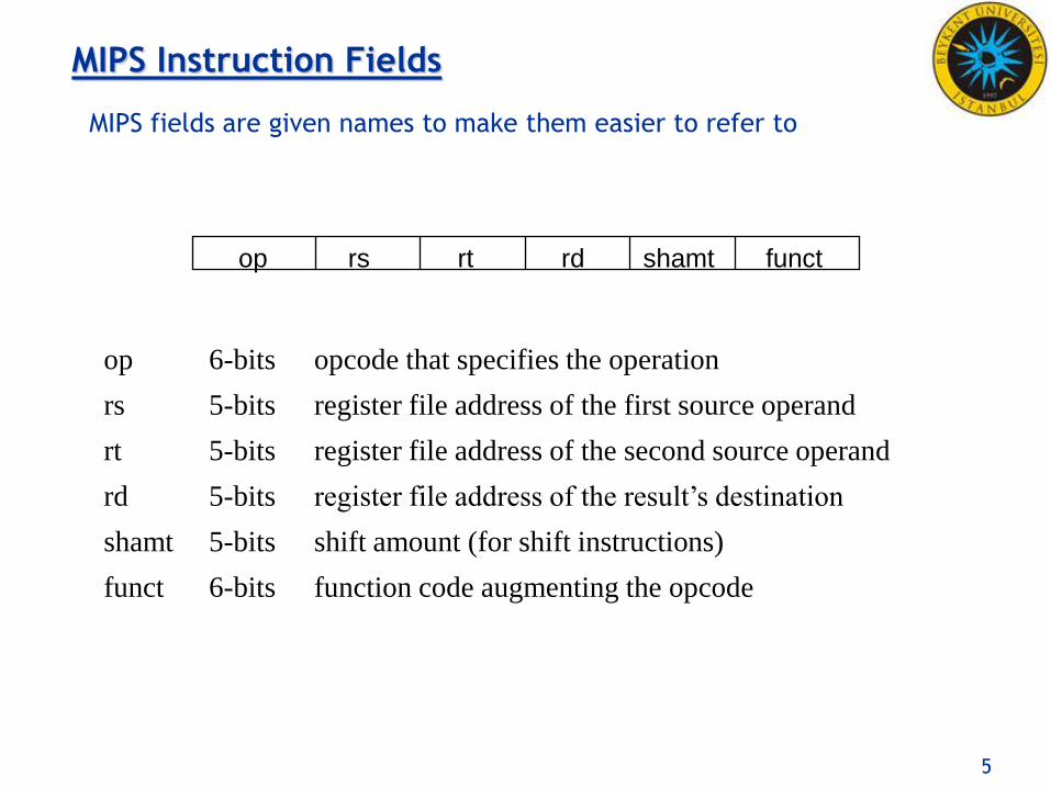
MIPS fields are given names to make them easier to refer to
MIPS Instruction Fields
op rs rt rd shamt funct
op 6-bits opcode that specifies the operation
rs 5-bits register file address of the first source operand
rt 5-bits register file address of the second source operand
rd 5-bits register file address of the result’s destination
shamt 5-bits shift amount (for shift instructions)
funct 6-bits function code augmenting the opcode
6
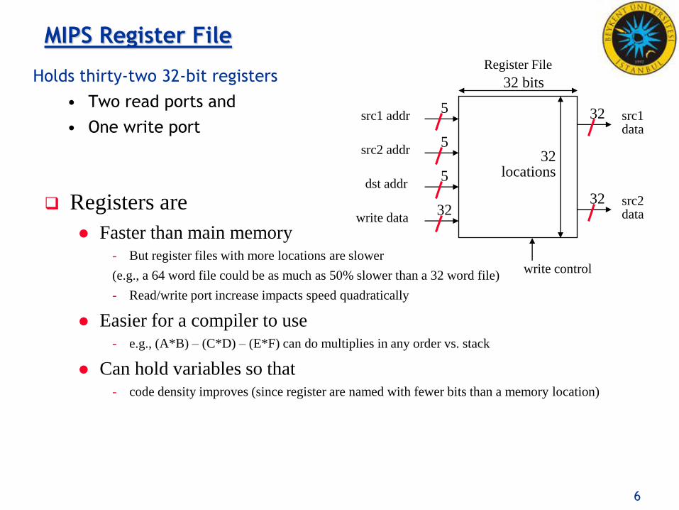
MIPS Register File Register File
src1 addr
src2 addr
dst addr
write data
32 bits
src1 data
src2 data
32 locations
32 5
32
5
5
32
Holds thirty-two 32-bit registers
• Two read ports and
• One write port
Registers are
Faster than main memory - But register files with more locations are slower
(e.g., a 64 word file could be as much as 50% slower than a 32 word file)
- Read/write port increase impacts speed quadratically
Easier for a compiler to use - e.g., (A*B) – (C*D) – (E*F) can do multiplies in any order vs. stack
Can hold variables so that - code density improves (since register are named with fewer bits than a memory location)
write control

7
MIPS Memory Access Instructions
MIPS has two basic data transfer instructions for accessing memory
lw $t0, 4($s3) #load word from memory
sw $t0, 8($s3) #store word to memory
The data is loaded into (lw) or stored from (sw) a register in the register file – a 5 bit address
The memory address – a 32 bit address – is formed by adding the contents of the base address register to the offset value
A 16-bit field meaning access is limited to memory locations within a region of 213 or 8,192 words (215 or 32,768 bytes) of the address in the base register

8
Load/Store Instruction Format (I format):
lw $t0, 24($s3)
Machine Language - Load Instruction
35 2410
Memory
data word address (hex)
0x00000000
0x00000004
0x00000008
0x0000000c
0xf f f f f f f f
$s3 0x12004094
2410 + $s3 = 0x120040ac
$t0

9
addi $sp, $sp, 4 #$sp = $sp + 4
slti $t0, $s2, 15 #$t0 = 1 if $s2<15
Machine format (I format):
MIPS Immediate Instructions
0x0A 18 8 0x0F
Small constants are used often in typical code
Possible approaches?
put “typical constants” in memory and load them
create hard-wired registers (like $zero) for constants like 1
have special instructions that contain constants !
The constant is kept inside the instruction itself!
Immediate format limits values to the range +215–1 to -215

10
MIPS Shift Operations
Need operations to pack and unpack 8-bit characters into 32-bit words
Shifts move all the bits in a word left or right
sll $t2, $s0, 8 #$t2 = $s0 << 8 bits
srl $t2, $s0, 8 #$t2 = $s0 >> 8 bits
Instruction Format (R format)
Such shifts are called logical because they fill with zeros
Notice that a 5-bit shamt field is enough to shift a 32-bit value 25 – 1
or 31 bit positions
0 16 10 8 0x00

11
MIPS Logical Operations
There are a number of bit-wise logical operations in the MIPS ISA
and $t0, $t1, $t2 #$t0 = $t1 & $t2
or $t0, $t1, $t2 #$t0 = $t1 | $t2
nor $t0, $t1, $t2 #$t0 = not($t1 | $t2)
Instruction Format (R format)
andi $t0, $t1, 0xFF00 #$t0 = $t1 & ff00
ori $t0, $t1, 0xFF00 #$t0 = $t1 | ff00
Instruction Format (I format)
0 9 10 8 0 0x24
0x0D 9 8 0xFF00

12
MIPS conditional branch instructions:
bne $s0, $s1, Lbl #go to Lbl if $s0$s1 beq $s0, $s1, Lbl #go to Lbl if $s0=$s1
• Ex: if (i==j) h = i + j;
bne $s0, $s1, Lbl1
add $s3, $s0, $s1
Lbl1: ...
MIPS Control Flow Instructions
Instruction Format (I format):
0x05 16 17 16 bit offset
How is the branch destination address specified?

13
Specifying Branch Destinations
Use a register (like in lw and sw) added to the 16-bit offset
• which register? Instruction Address Register (the PC)
- its use is automatically implied by instruction
- PC gets updated (PC+4) during the fetch cycle so that it holds the address of the next instruction
• limits the branch distance to -215 to +215-1 (word) instructions from the (instruction after the) branch instruction, but most branches are local anyway
PC Add
32
32 32
32
32
offset
16
32
00
sign-extend
from the low order 16 bits of the branch instruction
branch dst
address
?
Add
4 32

14
We have beq, bne, but what about other kinds of branches (e.g., branch-if-less-than)? For this, we need yet another instruction, slt
Set on less than instruction:
slt $t0, $s0, $s1 # if $s0 < $s1 then
# $t0 = 1 else
# $t0 = 0
Instruction format (R format):
Alternate versions of slt
slti $t0, $s0, 25 # if $s0 < 25 then $t0=1 ...
sltu $t0, $s0, $s1 # if $s0 < $s1 then $t0=1 ...
sltiu $t0, $s0, 25 # if $s0 < 25 then $t0=1 ...
In Support of Branch Instructions
0 16 17 8 0x24

15
More Branch Instructions
Can use slt, beq, bne, and the fixed value of 0 in register $zero to create other conditions
• less than blt $s1, $s2, Label
• less than or equal to ble $s1, $s2, Label
• greater than bgt $s1, $s2, Label
• great than or equal to bge $s1, $s2, Label
slt $at, $s1, $s2 #$at set to 1 if $s1 < $s2
bne $at, $zero, Label

16
MIPS also has an unconditional branch instruction or jump instruction: j label #go to label
Other Control Flow Instructions
Instruction Format (J Format):
0x02 26-bit address
PC
4
32
26
32
00
from the low order 26 bits of the jump instruction

17
MIPS procedure call instruction: jal ProcedureAddress #jump and link
Saves PC+4 in register $ra to have a link to the next instruction for the procedure return
Machine format (J format):
Then can do procedure return with a
jr $ra #return
Instruction format (R format):
Instructions for Accessing Procedures
0x03 26 bit address
0 31 0x08

18
MIPS Instruction Classes Distribution
Frequency of MIPS instruction classes for SPEC 2006
(Standard Performance Evaluation Corporation)
Instruction Class Frequency
Integer Ft. Pt.
Arithmetic 16% 48%
Data transfer 35% 36%
Logical 12% 4%
Cond. Branch 34% 8%
Jump 2% 0%

19
Addressing Modes Illustrated
1. Register addressing
op rs rt rd funct Register
word operand
op rs rt offset
2. Base (displacement) addressing
base register
Memory
word or byte operand
3. Immediate addressing
op rs rt operand
4. PC-relative addressing
op rs rt offset
Program Counter (PC)
Memory
branch destination instruction
5. Pseudo-direct addressing
op jump address
Program Counter (PC)
Memory
jump destination instruction ||

20
MIPS Organization So Far
Processor Memory
32 bits
230
words
read/write
addr
read data
write data
word address
(binary)
0…0000 0…0100 0…1000 0…1100
1…1100 Register File
src1 addr
src2 addr
dst addr
write data
32 bits
src1 data
src2 data
32 registers
($zero - $ra)
32
32
32
32
32
32
5
5
5
PC
ALU
32 32
32
32
32
0 1 2 3
7 6 5 4
byte address
(big Endian)
Fetch
PC = PC+4
Decode Exec
Add 32
32 4
Add 32
32 branch offset

21
Six Steps in Execution of a Procedure
1. Main routine (caller) places parameters in a place where the procedure (callee) can access them
• $a0 - $a3: four argument registers
2. Caller transfers control to the callee
3. Callee acquires the storage resources needed
4. Callee performs the desired task
5. Callee places the result value in a place where the caller can access it
• $v0 - $v1: two value registers for result values
6. Callee returns control to the caller
• $ra: one return address register to return to the point of origin

22
Determinates of CPU Performance
CPU time = Instruction_count x CPI x clock_cycle
Instruction_count
CPI clock_cycle
Algorithm
Programming language
Compiler
ISA
Core organization
Technology X
X X
X X
X X
X
X
X
X
X

23
32-bit signed numbers (2’s complement): 0000 0000 0000 0000 0000 0000 0000 0000two = 0ten 0000 0000 0000 0000 0000 0000 0000 0001two = + 1ten ...
0111 1111 1111 1111 1111 1111 1111 1110two = + 2,147,483,646ten 0111 1111 1111 1111 1111 1111 1111 1111two = + 2,147,483,647ten 1000 0000 0000 0000 0000 0000 0000 0000two = – 2,147,483,648ten 1000 0000 0000 0000 0000 0000 0000 0001two = – 2,147,483,647ten ...
1111 1111 1111 1111 1111 1111 1111 1110two = – 2ten 1111 1111 1111 1111 1111 1111 1111 1111two = – 1ten
Number Representations
maxint
minint
Converting <32-bit values into 32-bit values
copy the most significant bit (the sign bit) into the “empty” bits 0010 -> 0000 0010
1010 -> 1111 1010
sign extend versus zero extend (lb vs. lbu)
MSB
LSB

24
MIPS Arithmetic Logic Unit (ALU)
Must support the Arithmetic/Logic operations of the ISA
add, addi, addiu, addu
sub, subu
mult, multu, div, divu
sqrt
and, andi, nor, or, ori, xor, xori
beq, bne, slt, slti, sltiu, sltu
32
32
32
m (operation)
result
A
B
ALU
4
zero ovf
1 1
With special handling for
sign extend – addi, addiu, slti, sltiu
zero extend – andi, ori, xori
overflow detection – add, addi, sub