mirko castagnetti deliverable d2 · 1 mirko castagnetti deliverable d2.1 screening of suitable...
TRANSCRIPT

1
Deliverable D2.1
Screening of suitable mooring systems
Barbara Zanuttigh Luca Martinelli
Mirko Castagnetti

2
Screening of suitable mooring systems
by
Barbara Zanuttigh
Luca Martinelli Mirko Castagnetti
Aalborg University Department of Civil Engineering
Structural Design of Wave Energy Devices

3
Index
PREFACE .............................................................................................................................................. 4
1. INTRODUCTION ............................................................................................................................. 4
2. REGULATIONS AND NORMS ....................................................................................................... 5
3. FUNCTION REQUIREMENTS OF F-WEC MOORING .................................................................. 6
4. AN APPROACH TO DESIGN OF F-WEC MOORING.................................................................... 7
4.1 DESIGN PHASE .............................................................................................................................. 8
4.1.1 CHOICE OF MOORING SYSTEM TYPE .............................................................................................. 8
4.2 GENERAL LAYOUT, SHAPE AND NUMBER OF MOORING LINES ............................................................... 11
4.3 CABLE COMPOSITION ................................................................................................................... 12
4.3.1 VERTICAL LAYOUT ................................................................................................................. 12
4.3.2 THE CHAIN .......................................................................................................................... 14
4.3.3 THE CATENARY ..................................................................................................................... 16
4.3.4 SYNTHETIC LINES ................................................................................................................... 17
4.3.5 WIRE ROPES ........................................................................................................................ 20
4.3.6 COST OF THE LINE ................................................................................................................. 22
4.4 ANCHOR POSITIONING ................................................................................................................. 23
4.5 VERIFICATION PHASE ................................................................................................................... 25
4.5.1 EVALUATION OF FLOATING BODY MOVEMENTS ............................................................................. 25
4.5.2 VERIFICATION OF LINE AND ANCHOR .......................................................................................... 26
4.5.3 NUMERICAL MODELS ............................................................................................................. 28
CONCLUSIONS .................................................................................................................................. 29
REFERENCES ..................................................................................................................................... 30

4
Preface
Objectives of this report are to provide and overview of the mooring systems and specifically
to answer the following questions:
What are the needs? Function requirements of moorings for Wave Energy Converters (WECs).
What is it? Description of mooring systems.
Which software can be used. List commercial software to evaluate the real behavior of
moored device under extreme wave loads.
1. Introduction
The loads acting on WECs are very high and at the same time difficult to compute a priori
(Sannasiraj et al., 1998; Zanuttigh et al., 2009, Martinelli et al., 2008; Loukogeorgaki and Angelides,
2005). If the device is installed offshore, in deep water, it can convert a big quantity of energy,
because a very little part is lost by friction with the seabed. Although nearshore devices may result
competitive at the present state of development (Boccotti, 2003), offshore WECs are exposed to a
stress undoubtedly greater than nearshore ones (Ruol et al., 2009). Extreme loads, to which the
device must resist, are higher and are directly responsible for the costs of WECs (Masuda et al.,
2002), while the energy to be sold is produced in ordinary load conditions (Falcão and Rodrigues,
2002).
Moreover, the offshore placement of WECs may result in lower attenuation of the waves
approaching the shore. Such aspect represents an interesting investigation field to integrate
energy conversion systems and coastal protection measures.
The mooring design has been known in engineering’s field for some years by the experience
from offshore structures (Isaacson & Nwogu, 1987) and shipbuilding. Despite this fact, a relatively
high rate of floating WECs have failed in their efforts because the mooring system was unable to
anchor. Functional and structural inadequacy may affect also the efficiency of energy conversion
(Martinelli et al., 2009). In fact, the moorings must ensure that the device remains close to the
point where it was originally placed, but at the same time, they must allow the relative movement
of the device to convert a sufficient quantity of energy.
There is no experimental database that allows systematic analysis of working conditions of
WECs. Some large-scale prototype scale (see also www.pelamiswave.com,

5
www.oceanpowertechnologies.com, www/wavegen.co.uk) could provide in the coming years a
significant deepening of construction technology through monitoring campaigns.
The existing models have not provided so far criteria for design, stability, durability and
reliability of devices and moorings, so that field data based on physical model tests are required, in
order to fully evaluate the device behavior.
More reliable devices and lower management costs would certainly result in more
competitive energy production from wave energy market, leading to the benefits previously listed.
2. Regulations and norms
In the past, regulations, guidelines and norms have been provided by several authorities
whose their specific aims were to ensure the station keeping to offshore gas and oil platforms
under extreme environmental loads (waves, winds, currents):
DNV (Det Norske Veritas): rules and regulations for the classification of ships, mobile offshore
platforms and other floating marine structures were established (see also www.dnv.com).
Classification and design criteria for mooring systems and their specific parts (chains, anchors,
etc.):
DNV-OS-E301 - Position Mooring;
DNV-OS-E302 - Offshore Mooring Chain;
DNV-OS-E303 - Offshore Mooring Fibre Ropes;
DNV-OS-E304 - Offshore Mooring Steel Wire Ropes;
DNV-RP-E304 - Damage Assessment of Fibre Ropes for Offshore Mooring.
API (American Petroleum Institute): regulations and guidelines for offshore oil and gas
platforms (floating and fixed) were provided. Issues as design and planning criteria for floating
structures, materials, station keeping, mooring and anchoring systems, fabrication,
installation and inspection, risk management, etc., are included into such regulations (see also
www.api.org).
ISO (International Organization for Standardization): standards and design criteria were
provided for anchoring and mooring systems of ships and offshore structures (ISO 3505:1975,
ISO 3730:1988, ISO 19900:2002, ISO 15084:2003, ISO 19901-6:2009).
ABS (American Bureau of Shipping): ABS offers practical standards for design, construction,
operation and maintenance of offshore installations:
Rules for building and classing of single point moorings (1996)

6
Guide for certification of Offshore mooring chain (1999)
Guidance notes on the application of synthetic ropes for offshore mooring (1999)
In general, the tolerable failure risk is much higher for offshore oil and gas installations rather
than for F-WECs (they are usually unmanned, so that F-WEC failure does not lead to a loss of
human life). However. redundancy, durability and reliability represent essential factors for a safe
employing of such devices. The mentioned norms and guidelines can be also adopted for F-WEC
mooring design.
More recently, Carbon Trust (2006) has provided recommended practices and a guide to
assessment and application of engineering standards for F-WECs. In such publication, guidance on
concept development, design, construction and life cycle processes during F-WECs in-service life
are provided.
3. Function requirements of F-WEC mooring
Floating Wave Energy Converters (F-WECs) require a mooring system in order to ensure
station keeping, and more specifically to limit the drift, ensure alignment of directional WECs with
the prevailing wave conditions, avoid impact with other structures and excessive loads on the
electric power umbilical.
In details the requirements are:
to maintain the floating structure on station within specified tolerances under normal
operating load and extreme storm load conditions, that is generally more severe and frequent
than for normal mooring installations;
the excursion of the device must not permit tension loads in the electrical transmission
cable(s) and should allow for suitable specified clearance distances between devices in
multiple installations; contact between mooring lines, or contact with the device itself must
be avoided;
the mooring system must be sufficiently compliant to the environmental loading to reduce
the forces acting on anchors, mooring lines and the device itself to a minimum (unless the
stiffness of the mooring itself is an active element in the wave energy conversion principle
used);
the mooring have to be sufficiently compliant to accommodate the tidal range at the
installation location, and sufficiently stiff to allow berthing for inspection and maintenance
purposes;

7
The mooring system should also require as little inspection and maintenance as possible over
the in-service life of the device. It should be possible to remove the F-WEC from the site (or
remove one F-WEC from energy farm), with easy re-installation, without damaging any
components or reducing the service life of the system.
The system should limit the environmental impact as much as possible. Environmental factors
to be considered include damage to the local environment, visual impact, and any effect on the
local eco-system.
4. An approach to design of F-WEC mooring
The design process concerns the configuration of the individual lines, their interaction with
the bottom (through drag embedded, pile, gravity, plate anchors), and the overall layout, i.e. the
disposition of the lines that is responsible of the correct orientation of the F-WEC relatively to the
predominant waves and of the possible weathervaning.
The design procedure can be articulated in design and verification phases (Fig.4.1).
Figure 4.1 - Conceptual scheme of design procedure for F-WECs mooring systems
8
4.1 Design phase
4.1.1 Choice of mooring system type
First, it is necessary to define a proper functional and geometrical classification for mooring
types:
Functional Classification
Passive mooring, if the station keeping is the only purpose and movements have a limited
effect on the device efficiency.
Active mooring, if the system stiffness is an important factor for the dynamic response of
the device. Such effects can offer resonance conditions in order to produce much more
energy;
Reactive mooring, if the mooring provides a reaction force. They are suited especially when
the Power Take Off (PTO) exploits the relative movements between the body and the fixed
ground.
Geometrical Classification:
Mooring systems can be basically classified on the basis of the layout configuration in: Spread,
Single Point and Dynamic Moorings.
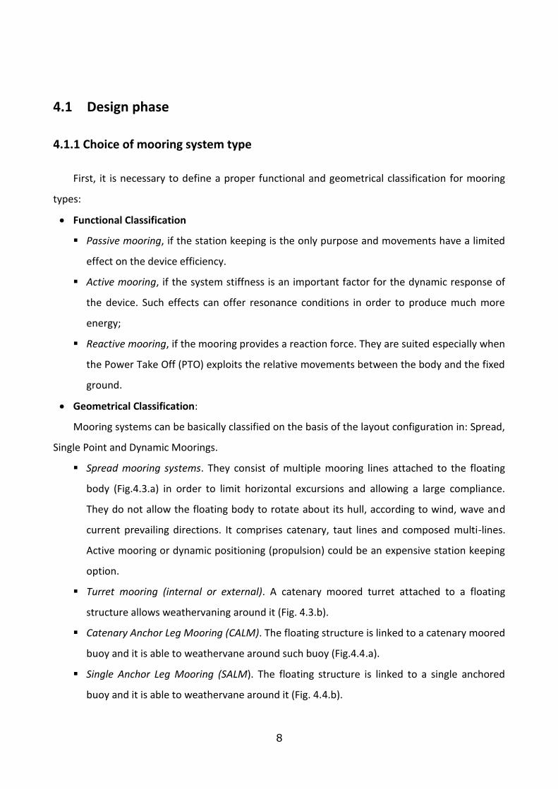
Spread mooring systems. They consist of multiple mooring lines attached to the floating
body (Fig.4.3.a) in order to limit horizontal excursions and allowing a large compliance.
They do not allow the floating body to rotate about its hull, according to wind, wave and
current prevailing directions. It comprises catenary, taut lines and composed multi-lines.
Active mooring or dynamic positioning (propulsion) could be an expensive station keeping
option.
Turret mooring (internal or external). A catenary moored turret attached to a floating
structure allows weathervaning around it (Fig. 4.3.b).
Catenary Anchor Leg Mooring (CALM). The floating structure is linked to a catenary moored
buoy and it is able to weathervane around such buoy (Fig.4.4.a).
Single Anchor Leg Mooring (SALM). The floating structure is linked to a single anchored
buoy and it is able to weathervane around it (Fig. 4.4.b).

9
Articulated Loading Column (ALP). The floating structure can weathervane around a
bottom hinged column, which has a swivel above the water line.
Fixed Tower Mooring. The floating structure is able to weathervane around the mooring
point which is composed by an anchored tower into the seabed.
A more liable alternative is the introduction of configurations typical of flexible risers such as
Lazy S, Steep S, Lazy Wave, Steep Wave or Pliant Wave could decrease the system stiffness
thereby reducing the mooring loads. The use of these multi-catenary mooring configurations could
provide flexibility in particular modes of motion required to improve the energy extraction for
wave activated F-WEC designs.
The most economic option for the lines is the free hanging catenary configuration.
Unfortunately this may not be able to allow for a sufficient extension without excessive loads
when the tidal range is large. Another disadvantage of such a configuration could be the
restraining stiffness affecting the F-WEC dynamic (Harris et al., 2004).
First and second classification can be combined to chose the best F-WEC mooring type.
(Fig.4.2).
Figure 4.2. – Comparison of the functional and geometrical classification.
Selection of the of proper mooring can be done using traditional methods in case of the
passive and reactive type. For active moorings, i.e. when the system stiffness is fundamental, the
process involves many iterative steps. The overall efficiency needs to be evaluated and – if not
correct - the design have to be reconsidered.
Fitzgerald (2009) proposes 3 examples of F-WECs and compares compliance and costs. From
his research, there should be a tendency to keep large structures to maintain mooring and
operational costs down. He also shows that costs of the mooring are quite essential in the F-WEC
sector (see Fig. 4.5). It may be concluded that, during F-WEC design, a detailed analysis of the
mooring system is fully justified.

10
a) b)
Figure 4.3. – Spread mooring system (a) and internal turret mooring (b) (API, 1987).
a) b)
Figure 4.4. – CALM (a) (Sagrilo et al.,2002) and SALM (b) (API, 2001)
Figure 4.5 Cost breakdown and relevance of mooring system for Oil floating platforms and for F-WECs (Fitzgerald, 2008).

11
4.2 General layout, shape and number of mooring lines
In this design step, the horizontal layout of mooring lines has to be chosen, considering the
2DH mooring system stiffness.
Line orientations are based on the hull geometry and on the prevailing directions of winds,
waves and currents. Several schemes to moor floating structures are currently provided, but they
can be ideally summarized as follows:
symmetric layouts;
asymmetric layouts.
Generally, the asymmetric mooring schemes are to be avoided, adopted only where strong
winds or currents come from one direction only or for steep bed variations, whereas the
symmetric ones are especially employed when the prevailing wind and current directions are very
variable. The most commonly used patterns are the 30-60° eight line and the symmetric eight line
(Fig. 4.6).

12
Figure 4.6. – An overview of the most used horizontal layout for mooring systems (API, 1987)
4.3 Cable composition
Lines are composed in general of a combination of metallic chains, metallic or synthetic wires.
Chains (see SubSection 4.3.2) are typically the first choice due to low cost and reliability. Synthetic
lines are used for special cases when low weights are required. It is frequently required that the
fraction of mooring line at the touchdown point is formed by a chain, more resistant to wear.
4.3.1 Vertical layout
Each individual line may be formed by a composition of different parts made of chain or wire,
with the addition of floats, clumps, or chain tails (drag chains) used as an alternative to a clump
weight.
The lines may be displaced in several configurations, possibly in combinations with a spring
buoy (e.g. surface buoy) which offer advantages such as reduced loads on F-WEC devices and
increased vertical F-WEC clearance. Figures 4.7 - 4.11 show the possible chain configurations
according to Fitzgerald ( 2009), which mainly differ for the horizontal/vertical load-displacement
curves: it is evident that in some cases the vertical load depends on the displacement in a non-
linear way (cases in Fig. 4.7 and 4.11), in other cases is almost negligible (Fig. 4.9 and 4.10) and on
other cases it is important but essentially constant (Fig. 4.10).
The stiffness matrix, more precisely the mixed terms in the horizontal, vertical and rotational
degrees of freedom (DOF), can significantly change due to different vertical adopted layouts.
Figure 4.7 - Simple Catenary mooring (Fitzgerald, 2009)

13
Figure 4.8 - Catenary mooring with added surface buoy (Fitzgerald, 2009
Figure 4.9 - Catenary mooring with added surface buoy and clump weight (Fitzgerald, 2009
Figure 4.10 - Vertical loaded anchor with compliance using weights and buoys (Fitzgerald, 2009

14
Figure 4.11 - Tension tether. Vertically loaded anchor with compliance using cable elasticity (Fitzgerald,
2009
4.3.2 The chain
The chain has shown durability in offshore operations. It has better resistance to bottom
abrasion and contributes significantly to anchor holding capacity. Moreover, the chain provides a
good catenary mooring stiffness to comply horizontal and vertical excursions. It is also particularly
suitable for long term mooring systems but it requires periodic inspections and maintenance to
keep it clean from bio-fouling that can increase the weight per unit and also damage the chain due
to excessive abrasion, caused by relative rotation of the links (API, 1999). Moreover, cathode
corrosion represents a possible threaten for chain integrity. Possible methods to avoid cathode
corrosion can be essentially divided into active or passive methods. Active ones include the
possibility to use an external cathode which focuses the corrosion over it. Passive ones consist of
an outer chain cover by a polymeric layer (jacket) that isolates the chains from undesired electric
currents. Nevertheless, passive cathode protection tends to be infrequently adopted, since the
outer polymeric layer will be quickly removed due to relative movements of the chain elements
(Harris et al.,2004).
At present, two types of chain are commonly employed:
open link (Fig. 4.12.a);
stud link (Fig. 4.12.b)
Studless steel chains are usually used, being reliable also in terms of fatigue, although stud
link chains tend to get entangled less than open links.
Chains can be obtained in several grades, which are characterized by a different proof tensile
strength (Tab. 4.1). In general, three grades (RQ3, RQ3S and RQ4) are provided for offshore

15
mooring systems, whereas grade RQ5 is characterized by the highest proof tensile strength (ABS,
1999.a). Oil Rig Quality (ORQ) or RQ3 chain has been sold in large quantities industry wide and has
generally performed well.
Figure 4.12 – Chain types (ABS 1999.a)
Figure 4.13 – Chain standard dimensions (ABS 1999,a)
Figure 4.14 – Chain quality grades (ABS 1999,a)

16
4.3.3 The catenary
An idealized hanging chain or cable in static conditions when supported at its ends and acted
on only by its own weight assumes a catenary shapes. Such curve is the graph of the hyperbolic
cosine function, and has a U-like shape, superficially similar in appearance to a parabola (though
mathematically quite different).
Figure 4.15. Catenary formulation
First of all, a general formulation of the catenary equations has to be provided (Fig. 4.15). In
such formulation, it is assumed that the catenary is hanging in points A and B. The point V
accounts for the lowest point of the catenary, whereas a generic point P on the arch between V
and B is taken. Horizontal and vertical forces in P are then are considered, respectively t and a.
A relation between p and t by means of tan can be given through Eq. [1]:
dx
dyttp tan
[1]
At the same time, p can be written as the weight of VP arch, considering a constant linear density
0:
P
V
x
x
dxdx
dygp
2
0 1
[2]
By matching Eq.s [1] and [2], the following equation can be obtained:
x
xV
dxdx
dyg
dx
dyt
2
0 1
[3]
By deriving first and second member along x axis, Eq. [3] becomes:
2
02
2
1
dx
dyg
dx
ydt
[4]

17
or alternatively:
kt
g
dx
dy
dx
yd
0
2
2
2
1
[5]
By solving the differential equation [5], the catenary formulation also for mooring lines can be
given:
1cosh
c
x
c
z [6]
c
x
c
ssinh [7]
w
Fc h [8]
where:
z = vertical coordinate [m]
s = line coordinate [m]
x = horizontal coordinate [m]
Fh = the constant horizontal force [N]
w = weight per unit length [N/m]
In actual practice, the chain is generally subject to other loads beside the weight, such as
those due to the direct wave action and the fairlead is connected to a moving body. In short, the
line does not behave like a pure catenary. The design should therefore account for at least the
following additional loads:
the inertia forces due to the chain accelerations;
drag and inertia forces due to the different velocity of the moving chain with respect to the
adjacent water, generally a combination of irregular wave with a coherent vertical structure
but quite variable in time and currents usually stratified in the vertical direction but rather
constant in time.
4.3.4 Synthetic lines
In order to minimize the vertical load on F-WECs, the alternative solution to chains are
synthetic line. Most common materials are nylon, polyster, polipropilene, kevlar, high density

18
polyetilene (Dyneema). Conversely from chains, where the resistant force is due to their weight,
the synthetic lines offer a resistance which depend on their elastic characteristics.
The weight and elasticity properties of the ropes make them more common for very deep
water tether applications. Axial compression and hysteretic heating may reduce the initial rope
resistance (although considerable change in axial stiffness after installation could require one or
more re-tensioning). Fish bites can represent a serious problem (Harris et al, 2004). Therefore,
fibre rope segments in mooring lines are normally protected by an outer jacket, which has an
adequate resistance to hydrolysis, chemical corrosion, creep phenomena, fish bites, friction and
shear, with a proper flexibility at minimum exposure temperatures in order to meet the
requirement to protect the rope core.
Figure 4.16 - Structure of a synthetic line
A synthetic line results from the assembly of different components in a hierarchic structure
which follows the production line, starting from the fibre that composes the line (Fig. 4.16).
The elastoplastic response of the line is very complex: a first permanent deformation occurs at
the first loading, which stretches the fibers for the first time; an important non-linear elastic
response is present at each successive loading, mixed to a plastic deformation or creep which is
due to a microscopic re-aligning of the fibers and that dissipates energy.
Such behavior can be described by the axial rigidity EA [N], which gives the proportionality
constant in the stress-strain relation. E is the elastic modulus and is not constant and, as
explained above, depends on the past load history (Fig. 4.17).
The design of the line section is carried out on the basis of the minimum breaking load (MBL).
Fig. 4.18 shows a comparison of MBL for different lines Vs diameter, for different materials:
polyester, steel and special polyester with high rigidity (HMPE), similar to that of steel itself.
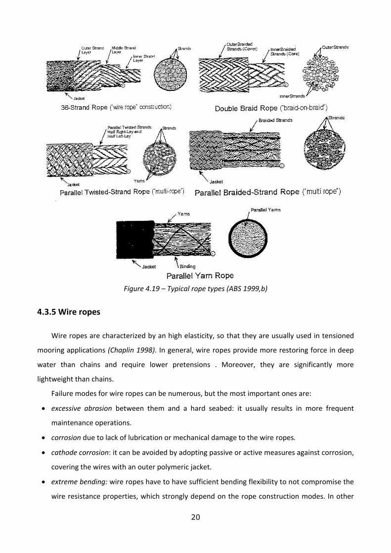
Examples of typical rope construction are given in Fig. 4.19.

19
Figure 4.17 - Qualitative stress-strain curve for a mooring line.
Figure 4.18- MBL function of line diameter, for different materials
20
Figure 4.19 – Typical rope types (ABS 1999,b)
4.3.5 Wire ropes
Wire ropes are characterized by an high elasticity, so that they are usually used in tensioned
mooring applications (Chaplin 1998). In general, wire ropes provide more restoring force in deep
water than chains and require lower pretensions . Moreover, they are significantly more
lightweight than chains.
Failure modes for wire ropes can be numerous, but the most important ones are:
excessive abrasion between them and a hard seabed: it usually results in more frequent
maintenance operations.
corrosion due to lack of lubrication or mechanical damage to the wire ropes.
cathode corrosion: it can be avoided by adopting passive or active measures against corrosion,
covering the wires with an outer polymeric jacket.
extreme bending: wire ropes have to have sufficient bending flexibility to not compromise the
wire resistance properties, which strongly depend on the rope construction modes. In other

21
terms, wire section shape is very important to ensure an adequate resistance to the bending
and torsion.
The most common used wire ropes are:
Spiral Strand (Fig.4.20.a) is the simplest of rope constructions. It consists of concentric helical
layers of wires. The outer layers of a spiral strand, which constitute the bulk of the cross
section, generally have wires of the same diameter, disposed in opposite helical senses and
with the same or similar helix angle. The outer surface is cylindrical, so that it facilitates the
cover by polymeric jacket to provide long-term protection. Moreover, spiral strands offer high
strength and stiffness for a given diameter and wire grade.
Six Strand (Fig. 4.20.b). This is a wire rope type widely used for general engineering purposes,
especially for offshore installation, as a component of mooring systems. Six or eight strand
ropes can be twisted around a core to form the strands (fibre or wire rope cores are
commonly used). For any given ultimate breaking load, this six strand wire rope tends to be
the cheapest of all. Despite this fact, since the outer layer are not cylindrical, it is not possible
to cover it with a polymeric jacket, so that these ropes are not generally selected for very long
term exposure to seawater. This rope has also good resistance to torsion loads.
Multi Strand ropes (Fig. 4.20.c) have two or more layers of strand, that are sometimes
compacted to improve the outer profile of the rope and the strand to strand contact stresses.
These ropes are commonly used offshore for applications requiring bending flexibility and
high tensional and torsion resistance. Such ropes have smaller outer wires than other ropes of
comparable strength, so that they tend to have lower corrosion resistance. Moreover, since
the contact area between the strands in different layers is much greater than other ropes,
fatigue damages tend to develop internally without any externally visible sign, leading to
unexpected strength loss and consequently to the mooring failure. Multi Strand ropes are
more expensive than conventional six strand ropes of similar strength.
Figure 4.20 – Typical wire ropes (Chaplin 1998)

22
Figure 4.21 – Typical failure modes. On the left, characteristic damage induced in spiral strand due
to torsion load, whereas on the right, damage of a six strand mooring wire ropes (Chaplin 1998).
4.3.6 Cost of the line
Figure 4.22 is the product of the SUPERGEN project. Companies were asked to provide price
information for chain, wire and fibre ropes. In Figure 4.23 the price per metre length is plotted
against the minimum breaking load. From the figure it can be seen cost differences between chain,
wire ropes and synthetic ropes are negligible: the choice for a mooring line material would be
more likely to be based on physical attributes and technical issues rather than cost. Assuming that
the mooring system is safe, costs are to be further related to instalment, maintenance, dismissal.
Fibre ropes require high safety factors since long term experience is not yet available, with the
result of higher installation costs.
The polymeric jacket protecting wire ropes should provide ideal long term mechanical
properties and higher maintenance periods. Chains have the advantage of ideal bending
properties and good seabed abrasion qualities, with predictable maintenance intervals and
inherent costs (Harris et al, 2004).

23
Figure 4.22 – Cost of different types of cable (Refer to Marlow Ropes, Sanmar Ltd. and ScanRope
AS for details).
4.4 Anchor positioning
The location and the use of a specific mooring configuration or mooring line material often
requires a specific anchor type (Musial et al, 2004):
Gravity anchor. Horizontal holding capacity is generated by one or more dead weights
providing friction force between seabed and anchor . The raw material is inexpensive but
massive amounts are needed to achieve the desired capacity in case of WECs.
Drag-Embedment Anchor. Horizontal holding capacity is ensured in the main instalment
direction by the embedment of the anchor in the seabed. Such anchors are suitable for
applications where anchor movements over time may not be critical. The weight of the chain
attached to the shank causes line tension to drive the fluke deeper. It is one of the lowest cost
anchor types and may be suited for catenary moored systems where placement precision is of
the order of a few meters and horizontal mooring forces do not exist.
Driven Pile/Suction Anchor. Horizontal and vertical holding capacity is generated by forcing a
pile mechanically or from a pressure difference into the ground, providing friction reaction
along the embedded length of the pile. Driven pile are the most commonly used anchors for
offshore oil production units, since many years of experience has proven that piles are very
reliable and can achieve high load capacity. Driven piles are installed vibrating the pile into the

24
seabed. Suction anchors, shown in Figure 4.23.b, are a commonly used alternative to the
driven-pile embedment anchor. The mooring line is directly attached to the upper part of the
pipe. Suction anchor is suited for catenary and taut mooring lines.
Vertical load anchor. Horizontal and vertical holding capacity is generated due to a specific
embedment anchor, allowing loads not only in the main instalment direction. These anchors
are designed to carry high vertical loads and can be more suitable for anchoring F-WECs which
have a dynamic response to environmental loads that characterize high vertical excursion.
Drilled and grouted anchor. Horizontal and vertical holding capacity is generated by grouting a
pile in a rock with a pre-drilled hole. The pile is similar in size and shape to a driven pile.
Drilled and grouted piles are more reliable and can achieve higher vertical loads than driven
piles, but are more expensive because they require heavy installation equipment.
Driven Anchor plate. The principle of this system is quite similar to that of the suction anchor.
One of the key advantages is that when tension loads are applied to the plate, it rotates in the
soil, allowing to involve a much larger wedge of soil with respect to suction anchor. Driven
plates can absorb very high vertical loads and they are particularly suited for taut mooring
lines.
a) b) c)
d) e)
Figure 4.23 a) Drag embedment anchor; b) suction anchor; c) driven pile; d) driven plate anchor all
from Musial et al, 2004; e) drilled pile anchors (from united states patent, June 1979)
25
4.5 Verification phase
This phase aims at evaluating the position and the stress on the mooring lines.
Main line loads are related to the movements of the fairlead of each line that are strongly
dependent from the movements of the floating body.
4.5.1 Evaluation of floating body movements
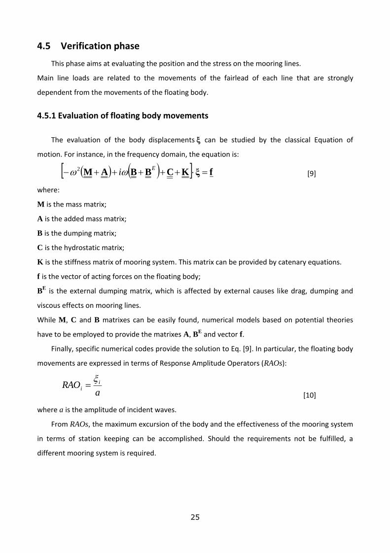
The evaluation of the body displacements can be studied by the classical Equation of
motion. For instance, in the frequency domain, the equation is:
fξKCBBAM E
i2 [9]
where:
M is the mass matrix;
A is the added mass matrix;
B is the dumping matrix;
C is the hydrostatic matrix;
K is the stiffness matrix of mooring system. This matrix can be provided by catenary equations.
f is the vector of acting forces on the floating body;
BE is the external dumping matrix, which is affected by external causes like drag, dumping and
viscous effects on mooring lines.
While M, C and B matrixes can be easily found, numerical models based on potential theories
have to be employed to provide the matrixes A, BE and vector f.
Finally, specific numerical codes provide the solution to Eq. [9]. In particular, the floating body
movements are expressed in terms of Response Amplitude Operators (RAOs):
aRAO i
i
[10]
where a is the amplitude of incident waves.
From RAOs, the maximum excursion of the body and the effectiveness of the mooring system
in terms of station keeping can be accomplished. Should the requirements not be fulfilled, a
different mooring system is required.

26
4.5.2 Verification of line and anchor
The equation of motion of a cable is given by:
1,,
,ft
vststT
st
st [11]
where t is the time variable, s is the curvilinear abscissa, v is the velocity vector, t is the tangential
vector, L is the length of the unstretched cable, is mass per unit length of unstretched cable, T
is tension, is strain and f is the sum of external forces (per unit length of unstretched cable)
acting on cable. By introducing the position vector r, we get
s
rt
1
1
[12]
so that
1
1
12
2
frr
sst [13]
an applying Hooke’s law, Eq. [13] leads to:
1
102
2
frr
sEA
st [14]
where E is Young’s modulus and A0 is the cross-sectional area of the unstretched cable.
Dynamic stress on all parts of the system can be computed after the F-WEC movements are
determined.
In general, a full dynamic analysis has to be performed and the equation of motion of the
body Eq. [9] can be coupled to the Eq. of the line dynamics (Eq. [14]).
In order to solve Eq.[14] the line may be divided in a finite number of elements (Fig.4.24.a).
For each element, constrains and DOFs are considered (Kreuzer et al., 2003). Element and node
tensions, relative motions, node positions and velocities and cable energy can be evaluated by the
implementation of the equation of motion for each element (Figure 4.24.b).
Snatching phenomena for mooring cable have to be avoided. Cable “snatching” can occur
when a cable is excited dynamically. Here, as the attachment point undergoes motion down
and/or horizontally towards the anchor, the slackening cable falling through the viscous fluid
reaches a terminal velocity and zero tension and a “slack” condition results (Fitzgerald, 2009). As
the attachment point then moves back up and/or horizontally away from the anchor, the falling
cable mass may stop and reverse its velocity, resulting in rapid accelerations of the cable mass and
corresponding impulsive tensions in the cable (Fig. 4.25). The impulse loads can be very high and

27
their magnitude are partly dependent on longitudinal elasticity of the cable, a property which can
slow down the impulsive accelerations (Fitzgerald, 2009), and partly on the cable kinetic energy
(Martinelli et al., 2009), so that infinitely large Young modulus is still associated to a finite load.
Finally, different external load conditions may be considered, including possible loss of one or
more cables, in order to assess also the reliability of the mooring system.
a) b)
Fig. 4.24 Subdivision of mooring line into a finite number of elements (Kreuzer et al., 2003).
Fig. 4.25 Dynamic tensions and “snatching” of simple chain catenary cable with attachment point
orbiting at a radius of 6 m at a period of 7 seconds in 50m water depth and for 3 scopes. The scope
is defined as the ratio of cable length to the water depth, d (Fitzgerald, 2009).

28
4.5.3 Numerical models
The assessment of the moored device behavior, in terms of mooring loads, mooring stiffness,
station keeping, is usually performed through experimental tests and/or numerical modeling. In
particular, experimental data are very useful to calibrate numerical models, in order to provide a
better description of the acting loads, cable stresses and line movements.
Numerical codes can be divided in two types, each focusing on one of the steps of the
complete analysis:
Model based on the irrotational wave theory to determine added masses, damping and wave
forces on F-WECs, i.e. the loads acting on floating bodies;
MSD models, solving the dynamic equations for a possibly large number of degrees of
freedom. They evaluate the joint dynamic behavior of the F-WECs and the mooring systems,
i.e. all the lines, the floaters and the clump weights.
In this section, an overview of the currently available numerical codes is provided.
WAMIT is a software that belongs to the first type of numerical codes. It implements the
linear and second-order potential theory to analyze floating or submerged bodies under ocean
waves. The BIEM method (Boundary Integral Equation Method) is used to solve for the velocity
potential and fluid pressures on the submerged surfaces of the bodies and simultaneously
accounts for the diffraction and radiation effects. Through such analysis, hydrodynamic
parameters like added-mass, damping coefficients, exciting forces, fluid pressure, fluid velocity
and RAOs can be easily established.
Another (free) software that is included into first type is SHIPSIM (available from
www.shipsim.com).
ORCAFLEX is included into second type of software. The full tridimensional modeling of
floaters and mooring systems can be performed using a finite element model with 6 DOFs. First
and second order wave theories are implemented to define acting wave loads on floaters. It has a
very broad range of applications and carries out very effective analysis, firstly for mooring system
(jetty mooring systems, turret moored systems, single point moorings, oceanographic and
aquaculture mooring systems), for buoy systems (catenary anchor leg mooring buoys, SPAR buoys,
Metocean buoys) and above all for F-WECs (wave power systems, offshore wind farm installation,
wind turbine modelling and power cable take-off).
MSC software, especially Ariane-3D, provides a complete time and frequency domain analysis
for mooring systems, including a nonlinear time domain dynamic analysis of individual lines. This

29
software is also suitable for shallow water mooring problems and for non-linear and multi-
elasticity component of mooring systems.
Finally, Ansys AQWA is a complete software package that includes both a first and a second
type numerical code. By implementing the first type code an engineering analysis of wave effects,
winds and currents on floating (buoys, ships, platforms, and still F-WECs) or fixed structure can be
performed. By implementing the second type code (Cable Dynamics) an analysis capabilities for
global performance of moorings and connecting systems subject to random sea loads, by static or
dynamic simulations, in the frequency and time domain can be carried out.
Figure 4.26 shows an AQWA application to the DEXA wave energy converter.
Figure 4.26 Example of application of AQWA to the DEXA wave energy converter.
Conclusions
Every mooring system is strongly site and device specific. Design requires knowledge on a vast
variety of different configurations. This report presented the most relevant mooring types for the
point of view of the floating wave energy converters. Unfortunately, the practical experience
relative to mooring of WECs is limited (and not published), so that knowledge in this field is still
limited. Reference was made to mooring systems of ships and floating oil and gas platforms, that
have slightly different characteristics and requirements. For instance, requirements of F-WECs
mooring systems are not only to maintain the device station keeping, but also to be sufficiently
compliant to reduce the WEC movements and reduce tension loads on the umbilical. A complete
list of characteristics is given above.

30
The design process has been described, as a cyclic procedure articulated in two phases: design
and verification. The procedure needs to be repeated since it must integrate to the design of the
hydrodynamics, the PTO and electrical control, and the wave by wave prediction.
In the design phase a selection was provided of the most suited mooring system among a
broad variety of types, which can be basically classified on the basis of geometrical and functional
aspects. Mooring materials (chains, synthetic ropes, wire ropes), 2DV (catenary, taut line) and 2DH
line configurations (symmetric or asymmetric disposition) have to be chosen to define the global
mooring system stiffness. Finally, basing on the acting forces on attachment point, the anchor type
is designed.
The second phase includes the static and dynamic analysis of the line movements and
stresses, in order to describe mooring behavior and, at the same time, identify the critical points
of the mooring system and possible failure modes that have to be avoided. Such analysis can be
performed by implementing governing equations into numerical codes. At present, most of these
codes are developed into commercial software, briefly recalled.
References
ABS (American Bureau of Shipping), 1996. Rules for Building and Classing Single Point Moorings, New York.
ABS (American Bureau of Shipping), 1999.a. Certification of offshore mooring chain, New York.
ABS (American Bureau of Shipping), 1999.b. Guidance note on the application of synthetic ropes for
offshore, New York.
API (American Petroleum Institute), 2001. Recommended Practice for Planning, Designing, and Constructing
Floating Production Systems, API recommended practice 2FPS, first edition.
API (American Petroleum Institute), 1987. Recommended Practice for the Analysis of Spread Mooring
Systems for Floating Drilling Units, RP 2P.
Boccotti P., 2003. On a new wave energy absorber. Ocean Engineering. 30, 1191-1200.
Chaplin C.R., 1998. Torsional failure of a wire rope mooring line during installation in deep water,
Engineering Failure Analysis 6, 67-82
DNV, 2005. Guidelines on design and operation of wave energy converters, Commissioned by the Carbon
Trust and carried out by DNV.
Falcão A., R. Rodrigues, 2002. Stochastic modelling of OWC wave power plant performance, Applied Ocean
Research, 24 (2), 59-71.
Fitzgerald J., 2009. Position mooring of wave energy converters,PHD thesisat the Chalmers Univerisity of
Technology, Goteborg, Sweden.

31
Harris R.E., Johanning L., Wolfram J., 2004. Mooring systems for wave energy converters: A review of
design issues and choices, Heriot-Watt University, Edinburgh, UK. (downloadable from
www.oreg.ca/docs/MooringSystems.pdf)
Isaacson M, Nwogu OU, 1987. Wave loads and motions of long structures in directional seas. Journal of
Offshore Mechanics and Arctic Engineering 1987; 109:126_32.
Kreuzer E., Wilke U.,2003. Dynamics of mooring systems in ocean engineering, Archive of Applied
Mechanics 73 (2003) 270 – 281 Springer-Verlag, DOI 10.1007/s00419-003-0288-3
Loukogeorgaki E, Angelides D, 2005. Stiffness of mooring lines and performance of floating breakwater in
three dimensions. Applied Ocean Research 2005; 27(4-5):187-208.
Martinelli, L., Zanuttigh, B. & J. P. Kofoed, 2009. Statistical analysis of power production from OWC type
wave energy converters, Proc. EWTEC 2009, su CD.
Martinelli L., P. Ruol, B. Zanuttigh, 2009. Impulsive loads on interconnected floating bodies, Proc OMAE, 8
pp, electronic version.
Masuda Y., T. Kuboki, T. Lewis, X. Liang and P. Sun, 2002. Prospect of Economical Wave Power Electric
Generator by the Terminator Backward Bent Duct Buoy (BBDB), Proceedings of XII ISOPE, Kitakyushu,
Japan, May 26–31, 607-613.
Musial W., Butterfield S., Boone A., 2004. Feasibility of Floating Platform Systems for Wind Turbines, To be
presented at the 23ASME Wind Energy SymposiumReno, Nevada January 5–8, (downloadable from
www.nrel.gov/docs/fy04osti/34874.pdf)
Ruol, P. Martinelli, L. & B. Zanuttigh, 2009. Loads on floating breakwaters: effects of layouts under oblique
waves, Proc. Coastal Eng. 2008, 5, 3875-3887.
Sagrilo L.V.S.,Siqueira M.Q., Ellwanger G.B., Lima E.C.P., Ferreira M.D.A.S., Mourelle M.M., 2002. A coupled
approach for dynamic analysis of CALM systems, Applied Ocean Research 24 47–58
Sannasiraj SA, Sundar V, Sundaravadivelu R. 1998. Mooring forces and motion responses of pontoon-type
floating breakwaters. Ocean Engineering; 25(1):27_48.
Winterstein S. R, Jha A. K., Kumar S., 1999. Reliability of floating structures: extreme response and Load
factor design, Journal of Waterway, Port, Coastal and Ocean Engineering, Vol. 125, No. 4, pp. 163-169
(downloadable from www.rms-group.org/RMS_Papers/pdf/alok/jcoastal99.pdf).
Zanuttigh, B., Margheritini L., Gambles, L. & L. Martinelli, 2009. Analysis of wave reflection from wave
energy converters installed as breakwaters in harbours, Proc. EWTEC 2009.