mission and vision of the department vision of mechanical
TRANSCRIPT

Mission and vision of the Department
Vision of Mechanical Department
To establish the state of the art learning center in Mechanical Engineering
which will impart global competence, enterprising skills, professional
attitude and human values in the student.
Mission of Mechanical Department
1. To impart quality technical education to the students.
2. To develop comprehensive competence in the students through various modes of
learning.
3. To enable students for higher studies and competitive examinations.
4. To facilitate students and industry professionals for continuous improvement and
innovation.
Program Educational Objectives:
[1] Use core competence acquired in various areas of Mechanical
Engineering to solve techno-managerial issues for creating innovative
products that lead to better livelihoods & economy of resources.
[2] To establish themselves as effective collaborators and innovators to
address technical, managerial and social challenges.
[3]To equip students for their professional development through lifelong
learning and career advancement along with organizational growth.
[4] Serve as a driving force for proactive change in industry, society and
nation.
PROGRAM SPECIFIC OUTCOMES
Student should have
1) An ability to work professionally in mechanical systems including design,
analysis, production, measurement and quality control.
2) An ability to work on diverse disciplinary tasks including manufacturing,
materials, thermal, automobile, robotics, mechatronics, engineering software
tools, automation and computational fluid dynamics.

EXPERIMENT NO. :-01
TITLE: - To generate involute tooth profile with help of rack on gear blank
AIM: - Generation of involute tooth profile using involute gear blank
PROCEDURE:-
1) Paper cut in circular form is fixed on circular disc having graduation on it.
2) Set the lower rack scale to zero position
3) By pencil mark out position of rack on paper
4) Rotate the disc by one graduation & again draw rack on paper.
5) Follow same procedure for number of time
6) Finally we will get tooth profile on paper.

• Pitch surface: The surface of the imaginary rolling cylinder (cone, etc.) that replaces
the toothed gear.
• Pitch surface: The surface of the imaginary rolling cylinder (cone, etc.) that replaces
the toothed gear.
• Pitch circle: A normal section of the pitch surface.
• Addendum circle: A circle bounding the ends of the teeth, in a normal section of the
gear.
• Dedendum circle or Root circle: The circle bounding the spaces between the teeth,
in a normal section of the gear.
• Addendum: The radial distance between the pitch circle and the addendum circle.
• Dedendum: The radial distance between the pitch circle and the root circle.
• Clearance: The difference between the Dedendum of one gear and the addendum of
the mating gear.
• Face of a tooth: That part of the tooth surface lying outside the pitch surface.
• Flank of a tooth: The part of the tooth surface lying inside the pitch surface.
• Top land: The top surface of a gear tooth.
• Bottom land: The bottom surface of the tooth space.
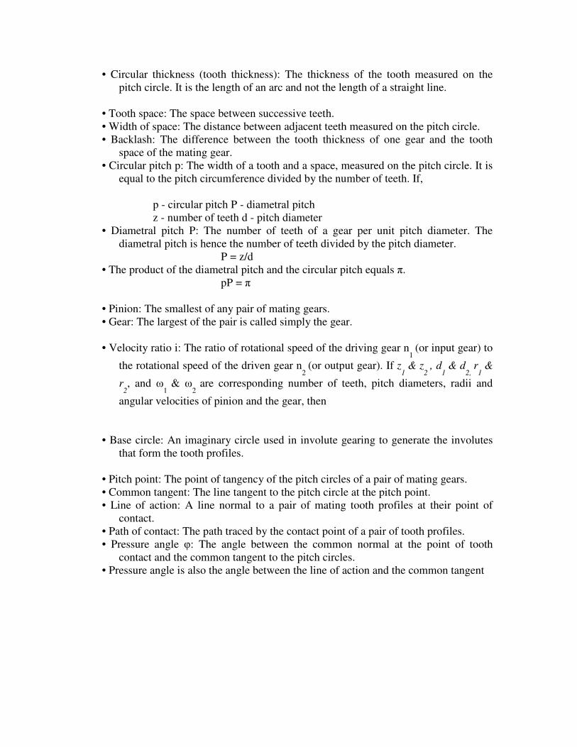
• Circular thickness (tooth thickness): The thickness of the tooth measured on the
pitch circle. It is the length of an arc and not the length of a straight line.
• Tooth space: The space between successive teeth.
• Width of space: The distance between adjacent teeth measured on the pitch circle.
• Backlash: The difference between the tooth thickness of one gear and the tooth
space of the mating gear.
• Circular pitch p: The width of a tooth and a space, measured on the pitch circle. It is
equal to the pitch circumference divided by the number of teeth. If,
p - circular pitch P - diametral pitch
z - number of teeth d - pitch diameter
• Diametral pitch P: The number of teeth of a gear per unit pitch diameter. The
diametral pitch is hence the number of teeth divided by the pitch diameter.
P = z/d
• The product of the diametral pitch and the circular pitch equals π.
pP = π
• Pinion: The smallest of any pair of mating gears.
• Gear: The largest of the pair is called simply the gear.
• Velocity ratio i: The ratio of rotational speed of the driving gear n1
(or input gear) to
the rotational speed of the driven gear n2
(or output gear). If z1
& z2
, d1
& d2,
r1
&
r2, and ω
1 & ω
2 are corresponding number of teeth, pitch diameters, radii and
angular velocities of pinion and the gear, then
• Base circle: An imaginary circle used in involute gearing to generate the involutes
that form the tooth profiles.
• Pitch point: The point of tangency of the pitch circles of a pair of mating gears.
• Common tangent: The line tangent to the pitch circle at the pitch point.
• Line of action: A line normal to a pair of mating tooth profiles at their point of
contact.
• Path of contact: The path traced by the contact point of a pair of tooth profiles.
• Pressure angle φ: The angle between the common normal at the point of tooth
contact and the common tangent to the pitch circles.
• Pressure angle is also the angle between the line of action and the common tangent


EXPERIMENT NO.02
Title :- Study Of Interference & Under Cutting
Theory :- To study of Interference & Under Cutting in toothed gearing.
“The Phenomenon when the tip of the tooth under cuts the root on it’s mating
gear is Known as interference.”
The radius of addendum of circle of pinion is increased on O1N the point of the
contract L will come or move from L to N when this radius is further increased L will be
inside the base of circle of the Wheel. The tip of the tooth will be under cut the tooth of
the wheel and remove part of the involutes profile of the tooth on the wheel this effect is
known as Interference and occur when the teeth are begin to cut.
If the radius of addendum circle of the wheel increases beyond O2N. Then the tip
of tooth of the wheel will cause interference with the tooth on the pinion. The points M
& N are called as interference points.
The interference may be avoided if point of contact between two teeth is always
as a involutes profile and both teeth in other word the interference may be prevented if
the addendum circle of the two mating gear cut the curve in tangent to the base circle
between the point of tangents.
MP = r sing φ; PN = R sin φ
Maximum length of contact = (R + r) sin φ
Are of contact = (R+ r) sin φ / cos φ = (R +r) tan φ

INVOLUTE GEAR TOOTH PROFILE

Minimum number of teeth on pinion in order to avoid interference
In order to avoid interference the addendum circle for both mating gears must
cut the common tangent to the base circle between point of tangency.
Let t = Number of teeth on pinion
T = Number of teeth on wheel.
M = Module of the teeth.
R = pitch circle radius of pinion.
G = Gear ratio = T/t = R/r
φ = Pressure angle or obliquity angle.
For O1N P,
=(O1N)2 = (O1P)
2 + (PN)
2 – 2 O1P PN cos O1NP
= r2 +R
2 – 2r. R sin φ = cos (90 + φ) [PN = O1P sin φ = R sin φ]
= r2 +R
2+sin
2φ + 2 r R sin2 φ ]
= r2 [1 + R
2sin
2φ / r2 + 2R sin
2φ/r]
= r2 [1 + R/r (R/r + 2) sin
2φ ]
Limiting radius of the pinion addendum circle
21 1 / ( / 2)sinO N r R r R r φ= + +
Let ApM = addendum of pinion where Aap is fraction by which the standard
addendum of one module for pinion should be multiplied in order to avoid
interference.
Addendum of pinion = O1 N – O1 P
2/ 2 1 / ( / 2)sin / 2ApM mt T t T t mtφ= + + −
2/ 2{ 1 / ( / 2) sin 1}mt T t T t φ= + + −
21 / ( / 2) sin 1
Apt
T t T t φ=
+ + −
The equation gives the minimum number of teeth required on the Wheel in order to
avoid interference.

Minimum number of teeth on wheel in order to avoid interference
Let T = Minimum number of teeth required on wheel to avoid interference.
Aw = Addendum of wheel, where Aw is fraction which the standard addendum for
wheel should be multiplied.
Let t = Number of teeth on pinion
T = Number of teeth on wheel.
M = Module of the teeth.
R = pitch circle radius of pinion.
G = Gear ratio = T/t = R/r
φ = Pressure angle or obliquity angle.
For O2M P,
=(O2M)2 = (O2P)
2 + (PM)
2 – 2 O2P PM cos O2MP
= R2 +r
2 – 2r. R sin φ X cos (90 + φ) [PM = O2P sin φ = r sin φ]
= R2 +r
2+sin
2φ + 2 R r sin2 φ ]
= R2 [1 + r
2sin
2φ / R2 + 2r sin
2φ/R]
= R2 [1 + r/R (r/R + 2) sin
2φ ]
Limiting radius of the wheel addendum circle
22 1 / ( / 2)sinO M R r R r R φ= + +
2/ 2 1 / ( / 2)sinMT t T t T φ= + +
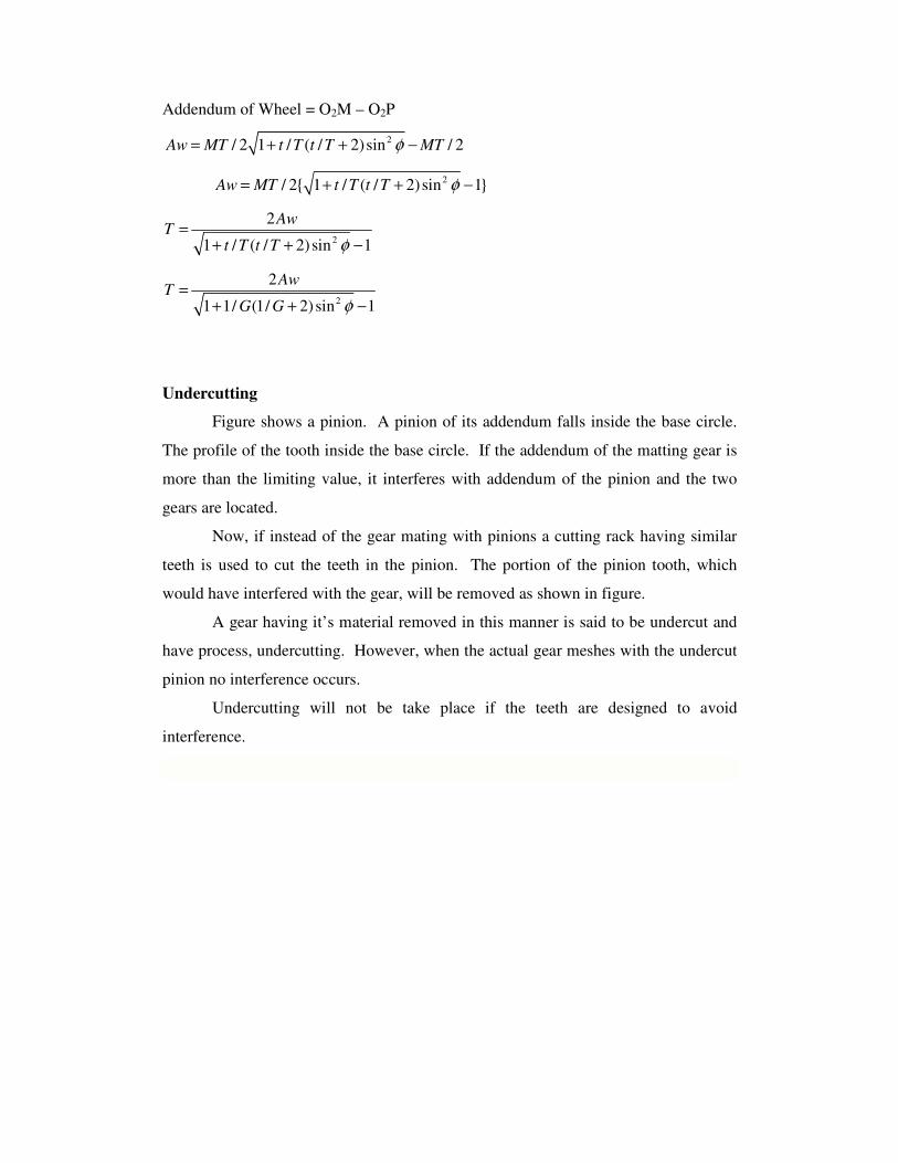
Addendum of Wheel = O2M – O2P
2/ 2 1 / ( / 2)sin / 2Aw MT t T t T MTφ= + + −
2/ 2{ 1 / ( / 2)sin 1}Aw MT t T t T φ= + + −
2
2
1 / ( / 2) sin 1
AwT
t T t T φ=
+ + −
Undercutting
Figure shows a pinion. A pinion of its addendum falls inside the base circle.
The profile of the tooth inside the base circle. If the addendum of the matting gear is
more than the limiting value, it interferes with addendum of the pinion and the two
gears are located.
Now, if instead of the gear mating with pinions a cutting rack having similar
teeth is used to cut the teeth in the pinion. The portion of the pinion tooth, which
would have interfered with the gear, will be removed as shown in figure.
A gear having it’s material removed in this manner is said to be undercut and
have process, undercutting. However, when the actual gear meshes with the undercut
pinion no interference occurs.
Undercutting will not be take place if the teeth are designed to avoid
interference.
2
2
1 1/ (1/ 2) sin 1
AwT
G G φ=
+ + −

Experiment No.03
Title:- Study Of Governor
The function of a Governor is totally different to that of a Flywheel. The former is
required to control the mean speed of a engine over a period of time as opposed to a
flywheel which is used to limit the almost inevitable fluctuations in speed, which
occur during one cycle. A good example of this is the single cylinder Four stroke
engine. There is only one power stroke to two revolutions of the crankshaft. Without a
flywheel, the speed would either fluctuate, within one cycle, by an unacceptable
amount or the engine would not work at all since the energy stored in the flywheel is
required to carry the engine through to the next Power Stroke.
A Boulton and Watt Rotative Engine made in 1797.
The Watt type Governor can be seen at the top of the picture.
A change in load on a engine will almost certainly lead to a change in speed and the
Governor is required to alter the supply of energy to the engine to bring the speed
back to its original value. This is achieved by connecting the rotating parts of the
governor, through suitable levers, to a sleeve on its axis of rotation. Any change in the
speed causes a change in the position of the rotating parts and consequently to the
sleeve and this movement actuates the fuel supply valve ( This includes Compressed
air; Steam or water) of the particular engine or turbine. This function is of particular
importance in A.C. electric generators since it is important to maintain the correct
number of cycles per second from the generator who's load may change rapidly and
unpredictably.
Generally Governors can be classified as either Centrifugal or Inertia

Centrifugal Governors
The effort of the governor is obtained from the change in centrifugal force on
(usually) two rotating masses known as Balls, when an increase or decrease in
governor speed occurs. Two main types can be distinguished.
Dead-weight Governors:
The radius of the ball path is controlled by lever and weights the latter being
usually attached to the sleeve as in the (a)"Watt" (b)"Porter" or (c) "Proell"
governors.
The equilibrium position can usually be determined by considering the
forces acting on one ball and the arm or arms to which it is attached. ( See
Examples 1,2 and 5)

Spring-loaded Governors.:
The balls are controlled by springs acting on them or the sleeve. Three
examples are shown in the diagram.
The Hartnell governor (a) is a well known example of this type. Each ball is
attached at one end of a bell-crank lever and at the other end to the actuating sleeve.
The method of analysis is to take moments about the pivot of the lever ( See
Examples 6,7 and 8)
Inertia Governors
Inertia Governors work on a different principle. The governor balls are arranged so
that the inertia forces caused by angular acceleration or retardation of the governor
shaft tend to alter their positions. The amount of the displacement of the balls is
controlled by springs and the governor mechanism to alter the supply of energy to the
engine.
The advantage of this type of Governor is that the positions of the balls are affected
by the rate of change of speed of the governor shaft. Consequently a more rapid
response to a change of load is obtained, since the action of the governor is due to
acceleration and not to a finite change of speed. The advantage is offset, however by
the practical difficulty of arranging for a complete balance of the revolving parts of
the governor. For this reason centrifugal governors are much more frequently used.
EXPERIMENT NO.04
Title: - To determine moment of inertia of uniform
rod by using -
A. Compound pendulum.
B. Bifilar suspention.

(A) Compound Pendulum Method
Aim: - To determine the mass moment of inertia of a uniform rod by
Using compound pendulum method.
Discription Of Set Up: - the compound pendulum consist of a steel
Bar. The bar is supported by knife-edge. It is possible to change the
Length of suspended pendulum by supporting the bar in different
Holes.
Procedure: -
1. Support the rod in any of the one hole.
2. Note the length of suspended pendulum and determine O to G.
3. Allow the bar to oscillate and determine time (t), by knowing the time
for 10 oscillations.
4. Repeat same procedure.
Theory: -
From fig.
Angular acceleration = α = d2θ/dt
2 = θ.
Torque T= Ioα =I o θ.
Restoring couple = mgx.
The magnitude of torque and restoring couple is same but there direction are
opposite.
Ioθ = - mgx.
Ioθ +mgx =0 .
But from fig
X = L sin θ = Lθ as θ is very small.
θ = β sin ωt
θ = β ω cos ωt
θ = -β ω2 sin ωt
= -β ω2 sin ωt
Io = - MgL
Io(-β ω2 sin ωt) = - MgLβ sin ωt
- ω2 Io = MgL = MgL/ ω2
ω= 2Πf BUT FREQUENCY = No of Oscillation / Time
Io = MgL/ 2Πf

Ig = Io - ML2
Observation -:
1. Mass of rod = m = gm
2. Length of O to G = L = cm
3. G = 9.81 M/S2
Observation Table
Sr,NO Oscillation Time
Calculation -:
FREQUENCY = F = No of Oscillation / Time
Io = MgL/ ( 2Πf ) 2
Ig = Io - ML2
IG = Kg .M 2
Result -:The mass moment of inertia of uniform rod = Kg m2
[B] Bifilar Suspension.
Aim -: To determine mass moment of inertia of uniform rod (Plate) by
Bifilar suspension method

Description Of Set Up : A uniform rectangular section bar is suspended from
pendulum support frame by two parallel cords. Top end of the card passes through the
two small chucks fitted at the top. Other ends are secured in the bifilar bar it is
possible to adjust the length of the card by loosening the chucks.
Procedure: 1) Suspended bar from chuck and adjust the length of the cord
conveniently. Note the suspension length of the each cord must be same
2) Allow the bar to oscillate about the vertical axis passing through the center and
measure the periodic time T by knowing the time for 10 oscillations.
Theory -: Let
T- be the tension in the string.
Arc - Lθ
Φ- Angular displacement of the string
θ- Angular displacement of the plate
g- Gravitational acceleration
a- Distance of C.G from string.
IG – M.M.I of plate about C.G. G
We have T = Mg /2
Arc LΦ = aθ Φ = aθ/ L
Torque = IGθ
Restoring couple = (TsinΦa)2a =TΦ2a [sinΦ = Φ]
= T(aθ/ L) 2a
Torque = Restoring couple
IGθ = - T(aθ/ L) 2a θ = β ω cos ωt
IGθ + T(aθ/ L) 2a = 0 θ = -β ω2 sin ωt
- IG ω2 + Mg a
2 /L =0 = -β ω2
sin ωt
IG = Mg a2 /Lω2
[ω = 2Π f ]
Frequency = No. Oscillation / Time Hz
Observations-:
1. Mass of the plate = M= gm
2. Length of plate = 2a = cm

3. Gravitational force = g= 9.81 M/ S2
Observation table -:
Sr. No Length Oscillation Time
1
2
4
Calculation -:
For L = cm
Frequency = No. Oscillation / Time Hz
= Hz
IG = Mg a2 /L2Π f
Result -: The mass moment of inertia of given body by bifilar method Kg M 2
EXPERIMENT NO.05
Title: - To determine moment of inertia of disc by using -
[a ] Trifilar suspention
[b ] Single rotor system
[a ] Trifilar suspention
Aim – To determine mass moment of inertia of disc by using trifler suspension
THEORY -: Suspended by three long flexible wire A, B, C as shown in fig when the
body is twisted about its axis through a small angle θ and then release will oscillate
with simple harmonic motion
For small displacement rθ = LΦ
Φ = rθ /L
Since the thee wire are attached symmetrically with respect to the axis there fore the
tension in each wire will be one third of weight of body
Tension in each wire = Mg / 3
Components at the tension in each perpendicular to r = Mg sinΦ /.3 = Mg rθ / 3L
Torque applied to each wire to restore the body to its initial equilibrium position
T = Mg rθ / 3L * r = Mg r2θ / 3L
Total restoring torque applied to three wires T == 3 Mg r2θ / 3L = Mg r
2θ / L ---[1]
We have disturbing torque = I∝ = MK2 ∝
θ / ∝ = L K2 / g r
2
Angular displacement
= L K2 / g r
2
Angular acceleration

Observation :-
1. Mass of disc is = kg
2. Radius r = cm
Observation Table :–
Sr. No. Length Oscillation Time
Calculation :-
1. Frequency = No. of oscillation / time Hz.
2. Mass moment of inertia = mk2
Frequency = f = r/ 2π k X g/L
Result :-
Mass moment inertia of the disc is kgm2.

(B) Single Rotor System
Aim :- To determine mass moment inertia of disc
Description Of Set Up :- One end of the shaft is griped in the chuck and heavy
flywheel free to rotate in ball bearing is fixed at the other end of the shaft.
The bracket with fixed end of shaft can be clamped at any convenient position
along lower beam. Thus length of the shaft can be varied during the expt specially
designed chuck are used for clamping end of the shaft the ball bearing support to the
flywheel provided negligible damping during expt. The bearing housing is fixed to
side member of mainframe.
Procedure: - 1) Fix the bracket at convenient position along the lower beam.
2) Grip one end of the shaft at the bracket by chuck.
3) Fix the rotor on the other end of the shaft
4) Twist the rotor through some angle and release.
5) Note down the time required for 10 to 20 oscillations
Theory :- d = diameter of the shaft
L = Length of shaft
Kt = Stiffness of rod
W = Wight of disc
Inertia torque = Iθ
Restoring torque = -Kt θ
Inertial torque and restoring torque both are equal but opposite in direction.
Iθ = -Ktθ
Iθ + Ktθ = 0
-w2 + Kt / I = 0
w = /Kt I
w = 2π f
Frequency = 1 / 2 π /Kt I
Observation :-
1) Shaft diameter =d= 0.4 cm
2) Diameter of disc = D = 25 cm
3) Weight of Disc = w = 4.2 kg
4) Modulus of rigidity for shaft G= 0.8 X 10⁶ Kg/cm
2
Observation Table :-
Sr. No. Length No. of Oscillation Time
1
2
3
Calculation :-
Determination of Torsional stiffness Kt = T/θ = GIp / L
Ip= Polar M.I. of Shaft = πd4/32
F= 1/2π /Kt I
Result :- Mass moment of inertia of disc = kg-m2

EXPERIMENT NO.06
Title :- To determine equivalent mass of a spring for a spring mass system.
Description Of Set Up :-
The arrangement is shown in fig. It is designed to study free forced damped and
undamped vibrations. It consists of M.S. rectangular beam supported at one end by a
trunnion pivoted in ball bearing. The bearing Housing is fixed to the side member of
the frame. The other end of the beam is supported by the lower end of helical spring.
Upper end of spring is attached to the screw.
The exciter unit can be mounted at any position along the beam additional known
weights may be added to the wt. Platform under side the exciter.
PROCEDURE :
1) Support one end of the beam in the slot of turnnion and clamp it by means
of screw.
2) Attach the other end of beam to the lower end of spring.
3) Adjust the screw to which the spring is attached such that beam is
horizontal in the above position.
4) Weight the exciter assembly along with discs and bearing and weight
platform.
5) Clamp the assembly at any convenient position.
6) Measure the distance L1 of the assembly from pivo. Allow system to
vibrate freely.
7) Measure the time for any 10 osc and find the periodic time and natural
frequency of vibrations.
8) Repeat the experiment by varying L1 and by also putting different weights
on the platform.
NOTE : It is necessary to clamp the slotted weights to the platform by means of out so
that weights do not fall during vibrations.
Calculations :
First calculate M.I. of the weight around the pivot.
w
I = (L1)2
g
where W = weight of exciter assembly along with weight and platform in Kg.
i.e. W= (‘m’ + added wt. in platform)
L1 = Distance of W from pivot in cm
K = Stiffness of the spring in Kg/cm.
L = Distance of spring from pivot = length of beam in cm
m = Mass of exciter assembly along with wt. platform.
∴ M= Kg.
∴ T(Theoretical) = 2πMe
K
where Me = equivalent mass at the spring = M[L12
/ L2]
Result :-
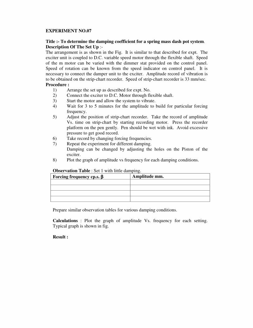
EXPERIMENT NO.07
Title :- To determine the damping coefficient for a spring mass dash pot system.
Description Of The Set Up :-
The arrangement is as shown in the Fig. It is similar to that described for expt. The
exciter unit is coupled to D.C. variable speed motor through the flexible shaft. Speed
of the m motor can be varied with the dimmer stat provided on the control panel.
Speed of rotation can be known from the speed indicator on control panel. It is
necessary to connect the damper unit to the exciter. Amplitude record of vibration is
to be obtained on the strip-chart recorder. Speed of strip-chart recorder is 33 mm/sec.
Procedure :
1) Arrange the set up as described for expt. No.
2) Connect the exciter to D.C. Motor through flexible shaft.
3) Start the motor and allow the system to vibrate.
4) Wait for 3 to 5 minutes for the amplitude to build for particular forcing
frequency.
5) Adjust the position of strip-chart recorder. Take the record of amplitude
Vs. time on strip-chart by starting recording motor. Press the recorder
platform on the pen gently. Pen should be wet with ink. Avoid excessive
pressure to get good record.
6) Take record by changing forcing frequencies.
7) Repeat the experiment for different damping.
Damping can be changed by adjusting the holes on the Piston of the
exciter.
8) Plot the graph of amplitude vs frequency for each damping conditions.
Observation Table : Set 1 with little damping.
Forcing frequency cp.s. ββββ Amplitude mm.
Prepare similar observation tables for various damping conditions.
Calculations : Plot the graph of amplitude Vs. frequency for each setting.
Typical graph is shown in fig.
Result :

EXPERIMENT NO.09
Title : Determination Of Gyroscopic Couple.
Theory : Consider a disc with an angular velocity “W” rad/sec about the axis of
spin ox in anticlockwise direction when seen from the front as shown in fig. Since
the plane in which the disc is rotating in parallel to the plane xoz is a horizontal
plane and the axis of spin rotates in a plane parallel to the horizontal plane about
an axis oy in other word the axis of spin is said to be rotating or processing about
an axis oy at an angular speed Wp rad/sec. This horizontal plane of processing
and oy is the axis of precision.
Let I = Mass moment of the Inertia of the disc about ox
W =Angular velocity of the disc
Angular Momentum of the disc = Iw
Since the angular Momentum is a vector quantify, therefore it may be
represented by vector ox as shown in fig. B the axis of spin ox is also rotating
anticlockwise when seen from the top about the axis oy let the axis ox is turned in
the plane xoz through a small angle so radians to the position ox in the time in sec.
Assuming the angular velocity w to be constant time angular momentum will now
be constant the angular momentum will now be represented by vector ox
Change of momentum = ox’ – ox = ox. dθ = I w dθ
Rate of change of angular momentum = Iw X dθ /dt
Since, the Rate of change of angular momentum will result by the application
of couple to the disc, therefore the couple applied to the disc causing precession.
C = Limit Iw X dθ /dt
st 0
C = I w X dθ / dt
C = I w wp wp = dθ /dt
Where wp = Angular velocity of precession of the axis of the spin ox the speed
of the rotation fo the axis of the spin about the axis of precession oy.
In si unit the unit of couple (c) N.M. Where I is kg-m2.
Observation :-
1) Mass of rotor = 7.1 Kg.
2) Diameter of rotor = 300mm = 0.3m
3) Distance of weight pan = 21cm =0.21
4) Thickness of disc = 11mm
Observation Table :
Sr. No. Speed
rpm
Weight
on pan
K.g.
dθθθθ
radi
dt
sec
Tact Tth

Calculation :-
Tact = Iwwp
Moment of Inertia of disc = I = Mr2
Angular velocity = w = 2πn / 60
Précis ional axis velocity wp = dθ /dt
Tth =w * L
Conclusion :- Verify the relationship T = Iwwp actually and theoretically.

EXERIMENT NO.08
Title :- To Obtain Experimentally
A) Frequency Response Curves
B) Transmissibility Curves
A) Frequency Response Curves:-
The equation of motion can be written as mx + cx + kx = F sin wt
This is the second order linear differential equation with constant coefficent. The
general solution of the above equation is
2 2
1 12 2 2
sin( )cos( 1 / )
[1 ( / ) ] [(2 / ) ]
nt sn
n n
X tx A e r t
ζω ω φε ω φ
ω ω εω ω
− −= − + +
− +
TOTAL RESPONSE :- The first part of equation vanishes with time while the second
part remains into existence. The amplitude remains constant due to second part and it
is called steady vibration. The vibration because of first part is called transient and it
occurs at the damped natural frequency of the system.
The complete solution of equation is the superposition of transient and steady
state vibrations which is shown in fig.
Characteristic Curves
The ration w/wn is called the frequency ration where w is the frequency of
excitation. Similarly, A/Xs is known as magnification factor or amplitude ration.
A curve between frequency ratio and magnification factor is known as
frequency response curve. Similarly a curve between phase angle and frequency ratio
is known as phase-frequency response curve. Both curves which are drawn with the
help of equations as shown in fig.
The following points are noted from these equations and figures
1. At zero frequency magnification is unity and damping does not have any
effect on it.
2. Damping reduces the magnification factor for all values of frequency.
3. The maximum value of amplitude occurs a little towards left of resonant
frequency.
4. At resonant frequency the phase angle is 900.
5. The phase angle increases for decreasing value of damping above
resonance.
6. The amplitude of vibration is infinite at resonant frequency and zero
damping factor.
7. The amplitude ratio is below unity for all values of damping which are
more than 0.70.
8. The variation in phase angle is because of damping. Without damping it is
either 1800 or 0.

B) Transmissibility Curves
Let us consider fig. For analysis. The spring and damping forces are kx and
cx respectively.
The amplitude of vibration is A, so the maximum value of these forces will be
kA and cwA respectively. The forces are perpendicular to each other because of
phase difference of 900 so their resultant FT is given as
2 2 2 2 2( ) ( ) ( )TF kA c A A k cω ω= + = +
In the above equation FT is the force transmitted to the foundation. The
disturbing force is F. The ratio of FT to F is called transmissibility. So it can be
expressed mathematically, as
T.R. = FT / F
From equation we have
2 2 2[1 ( / ) ] [2 / ]n nF Ak ω ω εω ω= − +
Substituting the values of F and FT in equation, we have 2 2 2
2 2 2. .
[1 ( / ) ] [2 / ]n n
A k cT R
Ak
ω
ω ω εω ω
+=
− +
2 2 2
2 2 2
(1 /
[1 ( / ) ] [2 / ]n n
c kω
ω ω εω ω
+=
− +
2
2 2 2
1 (2 / ). .
[1 ( / ) ] [2 / ]
nT
n n
FT R
F
εω ω
ω ω εω ω
+= =
− +
If FT/F = 0.25, then the system is said to have 25% transmissibility.
The following informations are available from equation :
1. The area of vibration isolation starts when transmissibility is less than
unity and w/wn > 2 . Thus when the frequency w of exciting force is
given, the isolation mounts can be designed such that w/wn > 2 . If w is
small the value of wn should be small and the value of natural frequency
( )n
k
mω = results from high value of mass or low value of stiffness.
Thus if the disturbing frequency w is low the isolation can be
accomplished by adding certain amount of mass to the system.
2. Damping is important specially at resonance otherwise TR will be
excessively large.
3. In the vibration isolation region w/wn > 2 , so equation in absence of
damping can be written as
2
1. .
( / ) 1n
T Rω ω
=−
4. Unity value of T.R. occurs at two points where w/wn is zero and 2 for all
values of damping.
5. Under ideal operating conditions, T.R. must be zero. Hence, w/wn should
be as large possible. Thus, the natural frequency of the system should be
small i.e. weak spring with fairly heavy mass.