mission impact through neuro-inspired design (mind ...the mission impact through neuro-inspired...
TRANSCRIPT

Mission Impact Through Neuro-Inspired Design (MIND)
Laboratory: Design Principles and Performance
Characteristics
by Christopher C. Stachowiak and Bruce E. Amrein
ARL-TR-6600 September 2013
Approved for public release; distribution is unlimited.
NOTICES
Disclaimers
The findings in this report are not to be construed as an official Department of the Army position unless
so designated by other authorized documents.
Citation of manufacturer’s or trade names does not constitute an official endorsement or approval of the
use thereof.
Destroy this report when it is no longer needed. Do not return it to the originator.

Army Research Laboratory Aberdeen Proving Ground, MD 21005-5425
ARL-TR-6600 September 2013
Mission Impact Through Neuro-Inspired Design (MIND)
Laboratory: Design Principles and Performance
Characteristics
Christopher C. Stachowiak and Bruce E. Amrein Human Research and Engineering Directorate, ARL
Approved for public release; distribution is unlimited.

ii
REPORT DOCUMENTATION PAGE Form Approved OMB No. 0704-0188
Public reporting burden for this collection of information is estimated to average 1 hour per response, including the time for reviewing instructions, searching existing data sources, gathering and maintaining the data needed, and completing and reviewing the collection information. Send comments regarding this burden estimate or any other aspect of this collection of information, including suggestions for reducing the burden, to Department of Defense, Washington Headquarters Services, Directorate for Information Operations and Reports (0704-0188), 1215 Jefferson Davis Highway, Suite 1204, Arlington, VA 22202-4302. Respondents should be aware that notwithstanding any other provision of law, no person shall be subject to any penalty for failing to comply with a collection of information if it does not display a currently valid OMB control number.
PLEASE DO NOT RETURN YOUR FORM TO THE ABOVE ADDRESS.
1. REPORT DATE (DD-MM-YYYY)
September 2013
2. REPORT TYPE
Final
3. DATES COVERED (From - To)
2011–2013 4. TITLE AND SUBTITLE
Mission Impact Through Neuro-Inspired Design (MIND) Laboratory: Design
Principles and Performance Characteristics
5a. CONTRACT NUMBER
5b. GRANT NUMBER
5c. PROGRAM ELEMENT NUMBER
6. AUTHOR(S)
Christopher C. Stachowiak and Bruce E. Amrein
5d. PROJECT NUMBER
5e. TASK NUMBER
5f. WORK UNIT NUMBER
7. PERFORMING ORGANIZATION NAME(S) AND ADDRESS(ES)
U.S. Army Research Laboratory
ATTN: RDRL-HRS-D
Aberdeen Proving Ground, MD 21005-5425
8. PERFORMING ORGANIZATION REPORT NUMBER
ARL-TR-6600
9. SPONSORING/MONITORING AGENCY NAME(S) AND ADDRESS(ES)
10. SPONSOR/MONITOR’S ACRONYM(S)
11. SPONSOR/MONITOR'S REPORT NUMBER(S)
12. DISTRIBUTION/AVAILABILITY STATEMENT
Approved for public release; distribution is unlimited.
13. SUPPLEMENTARY NOTES
14. ABSTRACT
The Mission Impact through Neuro-Inspired Design (MIND) Laboratory is an all-inclusive environment for neuroscience
research designed for studying Soldier-system interactions in support of the U.S. Army Research Laboratory’s (ARL’s)
neuroscience research. It provides three acoustically treated and electrically shielded chambers and a control room for
conducting multiple simultaneous human research studies in an environment that enables flexible environmental control. The
laboratory enables collaborative work among research personnel and facilitates the efficient use of research space and resources
while providing a comfortable environment for researchers and research participants. In the long term, the versatility afforded
by the MIND Laboratory provides increased flexibility for adapting to the changing research requirements that are driven by
rapid advances in neurotechnology.
15. SUBJECT TERMS
MIND laboratory, neuroscience, research facility
16. SECURITY CLASSIFICATION OF: 17. LIMITATION OF ABSTRACT
UU
18. NUMBER OF PAGES
80
19a. NAME OF RESPONSIBLE PERSON
Bruce E. Amrein a. REPORT
Unclassified
b. ABSTRACT
Unclassified
c. THIS PAGE
Unclassified
19b. TELEPHONE NUMBER (Include area code)
410-278-3529
Standard Form 298 (Rev. 8/98)
Prescribed by ANSI Std. Z39.18
iii
Contents
List of Figures v
List of Tables vii
Acknowledgments viii
1. Introduction 1
2. Background 1
3. Research Focus 2
3.1 MIND Experimental Suite Overview ..............................................................................3
3.1.1 Control Room (Chamber C) ................................................................................6
3.1.2 Crew Station and Driving Research Simulation Chambers
(Chambers A and B) ........................................................................................................7
3.1.3 Universal Research Area (Chamber D) ...............................................................7
4. Materials and Construction 8
4.1 Walls and Roof Panels ....................................................................................................8
4.2 Doors .............................................................................................................................12
4.3 Floor ..............................................................................................................................13
4.4 AC Power and Communications Circuit Isolation ........................................................14
4.5 HVAC ............................................................................................................................14
4.6 Lighting .........................................................................................................................15
4.7 Jack Panels ....................................................................................................................15
5. Testing 18
5.1 Acoustic Testing ............................................................................................................18
5.2 Radio Frequency Isolation Testing................................................................................24
6. MIND Laboratory Support Areas 27
6.1 Experimentation Clean-Up Area ...................................................................................27
6.2 Multifunction Collaboration Room ...............................................................................27
iv
6.3 Linux Laboratory ...........................................................................................................28
7. Conclusion 28
8. References 29
Appendix A. Fiberglass Panel Test Report 31
Appendix B. APG MIND Lab Noise Transmission Test Report 37
Appendix C. Radio Frequency Isolation Report 49
Distribution List 69

v
List of Figures
Figure 1. Basement floor plan: MIND Laboratory space and supporting facilities. ........................3
Figure 2. MIND Laboratory space before installation. (U.S. Army photo by Ron Carty.) .............5
Figure 3. MIND Laboratory chambers. ...........................................................................................6
Figure 4. MIND Laboratory: typical elevation view showing electrical and communications raceway, sound-absorbing wall panels, suspended ceiling, and roof. (Adapted from Noise Barriers, LLC, 2011.) .................................................................................................................9
Figure 5. Fabrication details: typical wall panel joint (plan view). (Adapted from Noise Barriers, LLC, 2011.) ...............................................................................................................10
Figure 6. Fabrication details: top of wall. (Adapted from Noise Barriers, LLC, 2011.) ...............10
Figure 7. Fabrication details: bottom of wall. (Adapted from Noise Barriers, LLC, 2011.) .........11
Figure 8. Fabrication details: typical interior wall intersection with roof. (Adapted from Noise Barriers, LLC, 2011.) ....................................................................................................11
Figure 9. Fabrication details: typical door sill construction. (Adapted from Noise Barriers, LLC, 2011.) ..............................................................................................................................12
Figure 10. Fabrication details: typical door seals (plan view). (Adapted from Noise Barriers, LLC, 2011.) ..............................................................................................................................13
Figure 11. Fabrication details: typical floor isolation fabrication technique. (Adapted from Noise Barriers, LLC, 2011.) ....................................................................................................13
Figure 12. MIND Laboratory RF filters. Panel A: communications filters; panel B: typical AC power filters. (U.S. Army photos by Ron Carty.) .............................................................14
Figure 13. Typical patch panel configuration. ...............................................................................16
Figure 14. MIND Laboratory: typical RF shielding, lighting controls, and patch panel installation. (U.S. Army photo by Ron Carty.) ........................................................................17
Figure 15. MIND Laboratory: typical instrumentation for acoustic testing. .................................18
Figure 16. Acoustic test measurement locations. ...........................................................................19
Figure 17. Leq equivalent measured airborne noise reduction (dB re: 20 µPa) in Chamber A. (Chart and graph adapted from Brune, 2013.) .........................................................................20
Figure 18. Leq equivalent measured airborne noise reduction (dB re: 20 µPa) in chamber B. (Chart and graph adapted from Brune, 2013.) .........................................................................21
Figure 19. Leq equivalent measured airborne noise reduction (dB re: 20 µPa) in chamber C. (Chart and graph adapted from Brune, 2013.) .........................................................................22
Figure 20. Leq equivalent measured airborne noise reduction (dB re: 20 µPa) in chamber D. (Chart and graph adapted from Brune, 2013.) .........................................................................23
Figure 21. Reverberation times (Brune, 2013). .............................................................................24

vi
Figure 22. MIND Laboratory: typical RF configurations and instrumentation. Panel A: loop antennas for magnetic field tests; panel B: log periodic antennas for plane wave tests; panel C: Giga-tronics RF signal generator; panel D: Hewlett-Packard spectrum analyzer. (U.S. Army photos by Ron Carty.) ..........................................................................................25
Figure 23. RF test measurement locations. ....................................................................................26
Figure 24. RF isolation test data, compared to required performance. (E = electric field; M = magnetic field; PW = plane wave field.) Error bars = ±1 standard deviation. .................26
Figure 25. MIND Laboratory. Panel A: main entrance to the control room; panel B: universal research area; panel C: crew station and driving research simulation chamber (typical); panel D: control room. (U.S. Army photo by Ron Carty.) ......................................................28

vii
List of Tables
Table 1. Typical patch panel configuration (quantity and type). ...................................................17
Table 2. Acoustic performance: test data, compared to specifications. .........................................23
Table 3. RF isolation test data, compared to required performance. .............................................27

viii
Acknowledgments
Based on operational needs outlined by members of the U.S. Army Research Laboratory’s
Translational Neuroscience Branch, the authors developed the technical requirements,
performance characteristics, and scope of work for fabrication and installation of the Mission
Impact through Neuro-inspired Design Laboratory space. The primary contractor for this work
was TechStar Industries, LLC (a division of Mid-Atlantic Acoustics), of Baltimore, MD; Noise
Barriers, LLC, of Libertyville, IL, designed the acoustically treated and electromagnetic
interference/radio frequency (EMI/RF) shielded chambers; Kibart, Inc.—Consulting Engineers,
of Towson, MD, —designed the heating, ventilation, and air conditioning and electrical systems;
Hi-Tech Services, Inc., of Ferndale, WA, installed the shielded chambers and performed the
EMI/RF testing; and Brune Consulting, LLC, of Towson, MD, performed the acoustic testing.

1
1. Introduction
The Mission Impact through Neuro-inspired Design (MIND) Laboratory is an environment
designed to accommodate the U.S. Army Research Laboratory’s (ARL’s) neuroscience research.
It provides a single flexible space for conducting multiple human research studies in an
environment that enables flexible environmental control for scientific experiments; it fosters
collaborative work among research personnel and facilitates the efficient use of research space
and resources while providing a comfortable environment for researchers and research
participants. The MIND Laboratory is located at Aberdeen Proving Ground, MD.
2. Background
Funding for the MIND Laboratory was provided by the Director of ARL in response to an
infrastructure upgrade proposal submitted by ARL’s Human Research and Engineering
Directorate (ARL-HRED) for improvements to laboratory spaces in one of ARL-HRED’s
buildings. This proposal was submitted in September 2010 to address necessary technological
advancements and growth in ARL-HRED’s research areas and changes to ARL-HRED’s
research spaces resulting from extensive renovations in the building.
Primarily, two issues caused inadequacies in the former neuroscience research facilities used by
ARL-HRED’s Translational Neuroscience Branch and ARL’s Neuroscience Strategic Research
Initiative (SRI). These issues include technological advancement in the state-of-the-art in
neuroscience and significant growth in the number of personnel utilizing the research spaces.
(There has been an eight-fold increase in on-site neuroscience personnel over the last five years.)
The research requirements for the MIND Laboratory have shifted since the former MIND
Laboratory facilities were originally developed for computer simulation and not for ARL-
HRED’s evolving focus on neuroscience as a primary research area. Facility inadequacies
included: lack of dedicated space, inadequate sound attenuation and electromagnetic
interference/radio frequency interference (EMI/RFI) shielding, necessary to conduct repeatable
experiments without the influence of confounding environmental variables, and external signal
contamination.
In the long-term, the versatility afforded by the MIND Laboratory provides increased flexibility
for adapting to the changing research requirements that are driven by rapid advances in
neurotechnology. Advancing these technologies will continue to be the basis of ARL’s
translational neuroscience efforts and will enable broad-reaching neuro-inspired system designs

2
that range from computer screen design to robotic control to brain-computer interfaces (BCIs). In
the mid-term, this newly installed research facility is the centerpiece for work on fundamental
neurocognitive performance and the development of methods and analysis techniques that can be
fielded for use in operational environments. The facility supports in-house research as well as
collaborations with numerous partners. Most notably, the MIND Laboratory is a primary
research facility for work conducted with the Cognition and Neuroergonomics Collaborative
Technology Alliance (CaN CTA), which is a collaborative effort between ARL, and private
industrial and academic partners (Oie et al. 2012).
3. Research Focus
The MIND Laboratory is an all-inclusive environment for neuroscience research designed for
studying Soldier-system interactions at multiple levels of inquiry with research paradigms
relevant to a range of basic and applied domains.
One of the primary areas of research within the MIND Laboratory is the study of the nature of
the interactions between Soldiers and systems within realistic operational environments. A
significant effort within this topic area focuses on improving our understanding of relevant
cognitive and perceptual processes revealed through the physiology of the nervous system.
With a focus on incorporating neuroscience-based concepts and tools, the research facility is
designed to ease subject testing while remaining extremely flexible as research requirements
change in the future. This space will be used for studies focusing on, but not limited to:
• Brain-computer interaction technologies,
• Soldier performance prediction,
• Multisensory information processing,
• Stressor effects on neurocognitive task performance,
• Individual differences in neurocognition,
• Visual scanning behavior,
• Adaptive information displays, and
• Cognitive metrics development and validation.
To support these research efforts, it is important to have controlled environments that are
acoustically and electronically shielded, and contain logistically suitable facilities for studying
participants in a variety of laboratory settings. Specifically, the goal is to move from more

3
simple, controlled-task environments to more complex simulated operational scenarios. This
space is used to conduct a significant portion of on-site ARL-HRED neuroscience research; as
such, it must be conducive to a wide spectrum of studies and research methodologies.
3.1 MIND Experimental Suite Overview
Because much of the research work focuses on a full spectrum of sensory, perceptual, and
cognitive studies, the laboratory spaces are acoustically isolated from each other and from the
main building, hallways, and surrounding offices to create environments suitable for
conducting repeatable experiments free from external distracters. In addition, the focus on
electroencephalography (EEG) and on advanced cognitive metrics, operator state classification,
and modeling of neural data requires the ability to limit and control the sources of electrical noise
that can interfere with participant EEG data collection.
The MIND Laboratory space is a 952-ft2 (88.4-m
2) portion of a suite of research and supporting
facilities located in the basement of the building. The partial basement floor plan is shown in
figure 1.
Figure 1. Basement floor plan: MIND Laboratory space and supporting facilities.

4
The MIND Laboratory space consists of modular acoustically treated and electrically shielded
chambers constructed from pre-engineered “QuietMod”* panel systems including wall and
ceiling panels, doors, windows, and silenced ventilation systems. These systems are
manufactured by Noise Barriers, LLC, of Libertyville, IL.
The MIND Laboratory space is approximately 28 ft (8.5 m) long and 34 ft (10.4 m) wide. The
elevation of the roof of the laboratory space is 10.33 ft (3.2 m) above the finished floor. This is
the maximum height permitted by the existing building structure.
Ambient lighting in the experimental rooms is provided by ceiling-mounted light-emitting diode
(LED) fixtures that are dimmable and digitally controllable from both the individual
experimental rooms and from the central control room.
The laboratory includes an independent heating, ventilating, and cooling (HVAC) system for
each chamber, sufficient to handle the large amount of personnel, equipment, and computing
activity expected in the MIND Laboratory. The systems also allow the heating and cooling
cycles to be controlled year-round regardless of outdoor temperature.
Throughout the laboratory, computer network and audio/video connections allow for: (1) easy
access to the laboratory intranet, (2) video monitoring of the experimental areas from multiple
areas within the control room and separate multifunctional rooms, and (3) audio communications
between the experimental areas and the control room.
The chambers are integrated into the life safety systems installed in the building (including
sprinkler, fire alarm, and mass-notification systems). Piping required for the sprinkler system
uses dielectric couplers at each penetration of the chambers to eliminate electromagnetic fields
created by currents in the piping. The entire MIND Laboratory was installed as an “equipment-
in-place” system. (Equipment-in-place is defined by the U.S. Army as personal property
consisting of capital equipment and other equipment of a movable nature which has been fixed in
place or attached to real property, but which may be severed or removed from buildings without
destroying the usefulness of the structures [DA PAM 420–11, 2010]).
Prior to installation of the research chambers, the basement space was an unused “fallout
shelter.” Figure 2 shows the space prior to installation of the MIND Laboratory space.
*QuietMod is a trademark of Noise Barriers, LLC, Libertyville, IL.

5
Figure 2. MIND Laboratory space before installation. (U.S. Army photo by Ron Carty.)
The floor plan of the MIND Laboratory chambers is shown in figure 3. The characteristics of
each chamber are described in the following sections.

6
Figure 3. MIND Laboratory chambers.
3.1.1 Control Room (Chamber C)
The control room is the primary experiment observation/oversight area for the entire laboratory.
It allows for experiment observation and communication within the experimental chambers and
houses specialized data acquisition and experiment control equipment (e.g., EEG, eye-trackers,
driving simulator). Additionally, this space serves as the primary area for informational tours and
VIP visits. The control room contains the hub of the MIND video/audio system. The control
room has the following characteristics:
• Dimmable ceiling-mounted recessed LED lighting system
• Double doors installed on each end of the control room provide a minimum sound
transmission class* of STC-50
*Sound Transmission Class (or STC) is an integer rating of how well a building partition attenuates airborne sound (ASTM
E90, 2009).

7
• All doors between the chambers provide a minimum of STC-50 isolation and RFI/EMI
shielding between spaces when closed
• Four “data drops,” each consisting of four CAT6 cables, are terminated in the control room
chamber. All cables are filtered at the entry points to maintain EMI/RFI integrality of the
research chambers
• Filtered 120-VAC, 20-A duplex receptacles are placed around the perimeter of the space
3.1.2 Crew Station and Driving Research Simulation Chambers (Chambers A and B)
The primary research capabilities in the MIND Laboratory include the crew-station modules and
driving simulators. They each require a separate chamber and areas for computer hardware and
experimental control in the control room. The studies conducted in these chambers require the
use of neurophysiological measures (e.g., EEG) and other physiological measures (e.g.,
electromyography [EMG] and electro-oculography [EOG]). These research spaces consist of two
sound-attenuated and electrically isolated/shielded chambers each having the following
characteristics:
• Dimmable ceiling-mounted recessed LED lighting system
• One filtered-jack panel to the control room
• One filtered-jack panel between the two crew station and simulation chambers
• Filtered 120-VAC, 20-A double-duplex receptacles centered in each wall
3.1.3 Universal Research Area (Chamber D)
The universal research area (URA) is a large reconfigurable area designed to permit
experimentation within a large space or for simultaneous experimentation in three portable and
reconfigurable sound isolation booths (WhisperRooms)* that can be installed as needed.
Additionally, many studies conducted in the URA require the use of neurophysiological
measures (e.g., EEG) and other physiological measures (e.g., EMG, EOG). The URA is a sound
and electrically isolated chamber with the following characteristics:
• Dimmable ceiling mounted recessed LED lighting system
• Three filtered-jack panels through to the control room
• Filtered 120 VAC, 20-A double-duplex receptacles every 8 ft around the perimeter of the
space
*WhisperRooms is a registered trademark of WhisperRoom, Inc., Morristown, TN.

8
4. Materials and Construction
4.1 Walls and Roof Panels
The prefabricated wall sections were assembled on top of the shielded floor. All walls of the
MIND Laboratory are constructed of 4-in- (10.2-cm)-thick modular panels rated as STC-50 with
16-gauge solid-steel sheets on both the exterior and interior of each panel. The interior space of
each panel is packed with insulation for acoustic attenuation. The roof panels are of the same
type of construction as the wall panels. Figure 4 shows an elevation view of typical chamber
construction. The space between the suspended ceiling and the underside of the roof panels
contains ductwork, electrical wiring, and sprinkler piping.
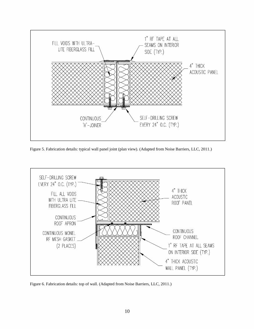
Panels are connected to each other with steel H-joiners, floor track, and roof channels that
provide a U-shaped channel into which each panel is inserted to provide a consistent acoustic
and EMI/RF seal between the H-joiner and the edges of the panels. Figures 5–8 show typical
joint connections between the various modular components.

9
Figure 4. MIND Laboratory: typical elevation view showing electrical and
communications raceway, sound-absorbing wall panels, suspended ceiling,
and roof. (Adapted from Noise Barriers, LLC, 2011.)
~ T/ROOF PANEL ( + )10'-4"
~ BOT/DROP CEILING (+)9'-0"
~ BOT/FABRIC PANEL (+)1'-8" ~
~ BOT /RACEWAY C (+)1'-4"
,1.. FINISHED FLOOR v (±)0'-0"
,.
\_ SUPPLYjR£1\JRN AIR GRILLE
DROP-IN GRID CEILING llLES
QUIETMOD H/ H-50 L_ 4" THICK ROOF PANELS
' 1" THICK FABRIC WRAPPED ;V SOUND ABSORBING WALL PANEL
: QUIETMOD H/H-50 1---- 4" THICK WALL PANELS
ELECllRICAL/COMMUNICAllON 'MRE RACEWAY (SUPPLIED AND INSTALLED BY OTHERS)
tf . 1" THICK FABRIC WRAPPED iV SOUND ABSORBING WALL PANEL
• FINISHED FLOOR .'
4" V1NYL BASEBOARD r (BY CONllRACTOR TYP. I SEE DETAIL 4/10)
10
Figure 5. Fabrication details: typical wall panel joint (plan view). (Adapted from Noise Barriers, LLC, 2011.)
Figure 6. Fabrication details: top of wall. (Adapted from Noise Barriers, LLC, 2011.)
11
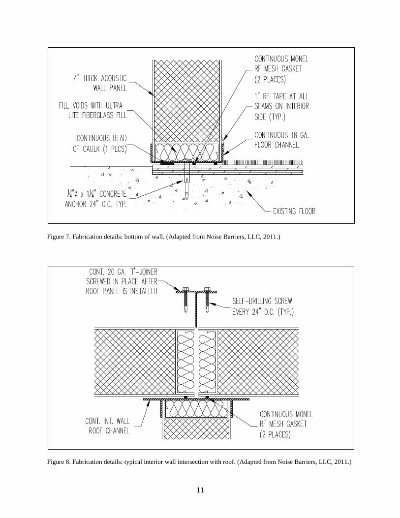
Figure 7. Fabrication details: bottom of wall. (Adapted from Noise Barriers, LLC, 2011.)
Figure 8. Fabrication details: typical interior wall intersection with roof. (Adapted from Noise Barriers, LLC, 2011.)

12
The inherent RF isolation characteristics of the steel walls are further enhanced with the use of
copper tape with conductive adhesive applied to all joints. RF gaskets were applied under the
wall sections and at all two-, three-, and four-way joints.
A suspended ceiling was installed approximately 8 in (20.3 cm) from the underside of the
chamber roof in all of the areas except for the first 4 ft (1.2 m) of the laboratory space (nearest
the corridor). This 4-ft bulkhead area was necessary to accommodate existing sprinkler and
sanitary sewer pipes and spans across chamber A, the control room, and chamber D. The finished
ceiling height inside the chambers is 9 ft (2.7 m) above the finished floor.
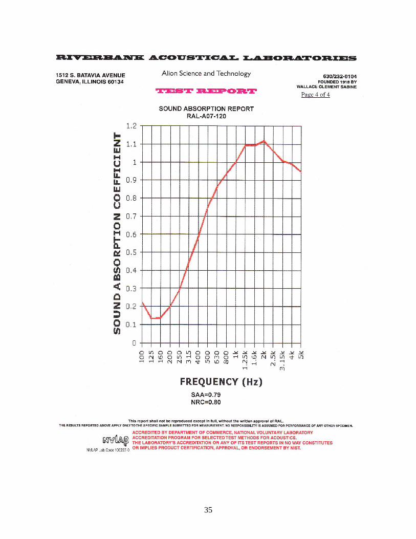
The interior of all wall surfaces from the floor to the underside of the suspended ceiling are
covered in 1-in-thick, cloth-wrapped fiberglass acoustic panels with a density of 6 lb/ft3
(96.1 kg/m3). These panels are attached with hook and loop fasteners and magnets to prevent
compromising the RF and acoustic integrity of the chambers. These fiberglass panels are
manufactured by Leading Acoustics, LLC, of Libertyville, IL. The acoustic characteristics of a
typical panel are shown in appendix A.
4.2 Doors
All doors are STC-50 rated and utilize cam-lift butt-type hinges. They include RF-conductive
mesh-covered acoustic foam to form a perimeter seal around the door frame. RF copper tape was
applied to the door surface making contact with the RF mesh to provide enhanced conductivity
and to prevent corrosion. The bottom of each door includes two individually adjustable seals;
one is a standard acoustic seal and the second uses RF finger seals to create an EMI/RF seal
when the door is closed. Doors from the control room chamber to the corridors each contain
lites; the other doors are solid. Door construction and sealing techniques are shown in figures 9
and 10.
Figure 9. Fabrication details: typical door sill construction. (Adapted from Noise Barriers,
LLC, 2011.)
13
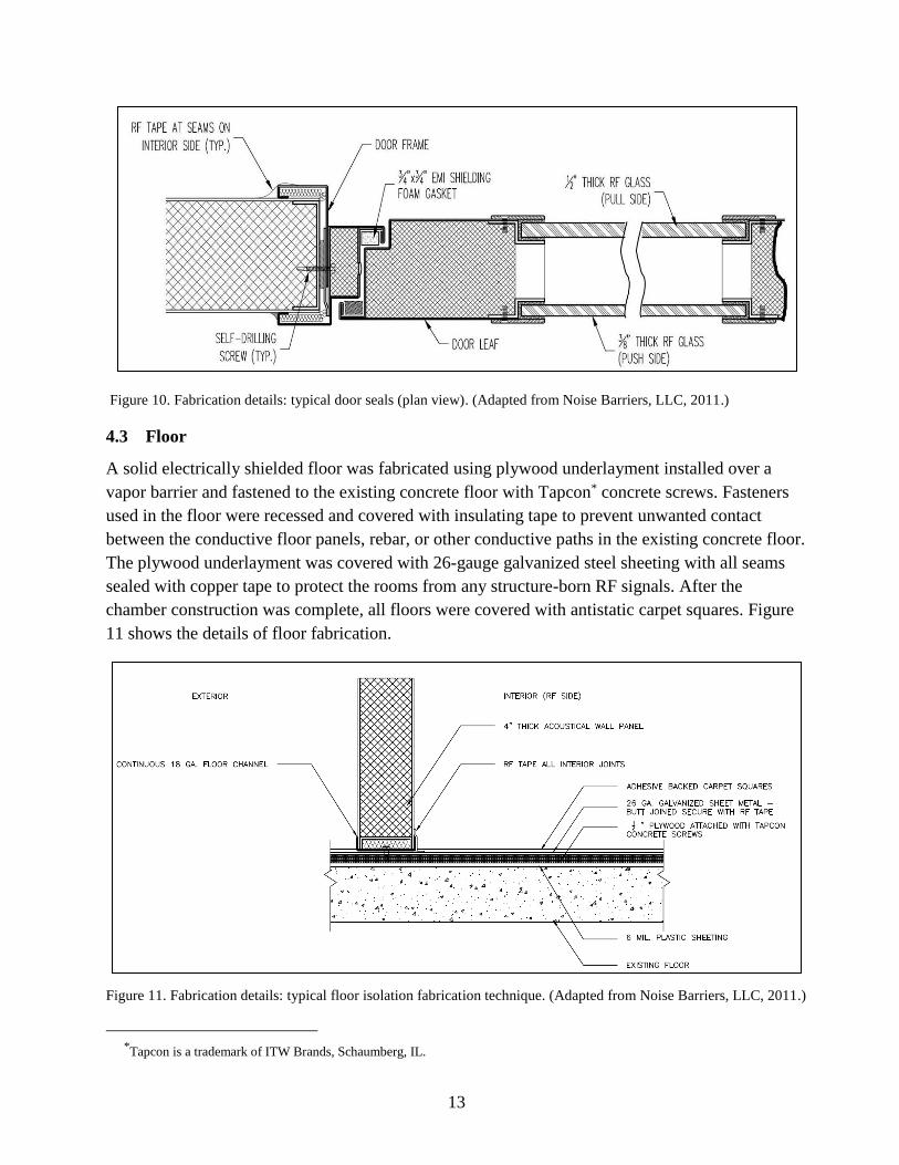
Figure 10. Fabrication details: typical door seals (plan view). (Adapted from Noise Barriers, LLC, 2011.)
4.3 Floor
A solid electrically shielded floor was fabricated using plywood underlayment installed over a
vapor barrier and fastened to the existing concrete floor with Tapcon* concrete screws. Fasteners
used in the floor were recessed and covered with insulating tape to prevent unwanted contact
between the conductive floor panels, rebar, or other conductive paths in the existing concrete floor.
The plywood underlayment was covered with 26-gauge galvanized steel sheeting with all seams
sealed with copper tape to protect the rooms from any structure-born RF signals. After the
chamber construction was complete, all floors were covered with antistatic carpet squares. Figure
11 shows the details of floor fabrication.
Figure 11. Fabrication details: typical floor isolation fabrication technique. (Adapted from Noise Barriers, LLC, 2011.)
*Tapcon is a trademark of ITW Brands, Schaumberg, IL.

14
4.4 AC Power and Communications Circuit Isolation
All electrical power for AC convenience receptacles and lighting is filtered with RF Filters. All
communications circuits (CAT6 cable) for network access and telephone circuits enter the
chambers through Fiber Optic Isolation Filters (FOILs). These filters are capable of gigabit
network speed. Figure 12 shows typical AC power and communications filters. The
communications filters are installed in roof panels above the control room, and AC power filters
are installed on the exterior of the research spaces in various locations.
Figure 12. MIND Laboratory RF filters. Panel A: communications filters; panel B: typical AC power filters.
(U.S. Army photos by Ron Carty.)
Fire alarm and mass-notification systems wires are fed into the enclosures with RF filters and
shielding specifically designed to meet the alarm system requirements.
4.5 HVAC
Each chamber is provided with a dedicated HVAC system consisting of self-contained individual
heat pump units. The air handler for each unit is installed in the ceiling spaces above the
chambers. The outside condenser units are installed at the rear of the building. Each supply and
return duct includes in-line wave guides and acoustic silencers designed to maintain the specified
acoustic and EMI/RF integrity of each chamber. The heat pumps utilize “low ambient kits”
suitable for operation to 0 °F (–17.8 °C). (Low ambient kits permit the heat pump to operate in
cooling mode to remove heat from the interior space when the outside temperature would
generally not require interior cooling.)
15
4.6 Lighting
The lighting system consists of Lunera Series 22-G3 recessed LED troffers each delivering up to
3625 lumens. The Lutron GRAFIK Eye* QS Control Unit is used to operate the lighting system,
allowing each chamber independent programmable dimming control. There are wall stations
mounted in each chamber with the master control installed in the control room chamber.
Computer interface to control or monitor the system is achieved via the Lutron QSE-CI-NWK-E
integration access point. This allows lighting control through either RS-232 or TCP/IP interfaces.
4.7 Jack Panels
Jack panels provide:
• Eight telephone/data RJ45, CAT6 jacks,
• Six DVI-I connectors,
• Two VGA connectors,
• Eight type A USB 2.0 connectors,
• Four type B USB 3.0 connectors,
• Two 3.5-mm stereo audio ring/tip/sleeve jacks,
• Three 3-pin XLR jacks,
• Three RCA jacks,
• Two DB-25 connectors (parallel),
• Two DB-9 connectors (serial),
• Four BNC connectors, and
• Two female FC fiber optic connectors per panel.
Each connector is insulated from the chamber and from the other connectors. The XLR, USB,
and DB connectors in the jack panels are configured with male on one side and female on the
other so configuration development can be accomplished in another area then unplugged and run
through the jack panel. An open area of 2 × 3 in (5.1 × 7.6 cm) is provided in each jack panel for
future expansion. The panels are designed to preserve the acoustical and EMI/RF integrity of
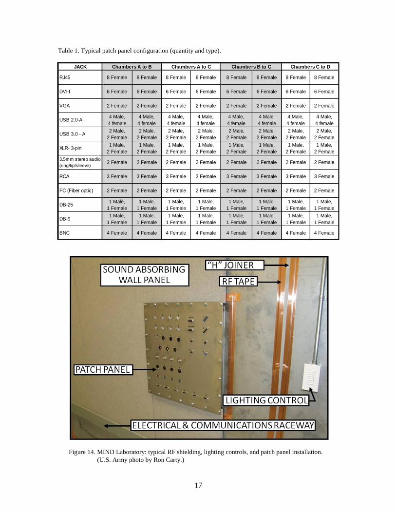
each chamber. Figure 13 shows the configuration of a typical jack panel. Table 1 lists types and
quantities of connectors provided in each jack panel.
Figure 14 shows a typical chamber during construction before all fiberglass panels were completely
installed. Note the attention to detail in sealing any potential opening with copper RF tape.
*Lutron GRAFIK Eye is a trademark of Lutron, Coopersburg, PA.

16
Figure 13. Typical patch panel configuration.
17
Table 1. Typical patch panel configuration (quantity and type).
Figure 14. MIND Laboratory: typical RF shielding, lighting controls, and patch panel installation.
(U.S. Army photo by Ron Carty.)
JACK
RJ45 8 Female 8 Female 8 Female 8 Female 8 Female 8 Female 8 Female 8 Female
DVI-I 6 Female 6 Female 6 Female 6 Female 6 Female 6 Female 6 Female 6 Female
VGA 2 Female 2 Female 2 Female 2 Female 2 Female 2 Female 2 Female 2 Female
USB 2.0-A4 Male,
4 female
4 Male,
4 female
4 Male,
4 female
4 Male,
4 female
4 Male,
4 female
4 Male,
4 female
4 Male,
4 female
4 Male,
4 female
USB 3.0 - A2 Male,
2 Female
2 Male,
2 Female
2 Male,
2 Female
2 Male,
2 Female
2 Male,
2 Female
2 Male,
2 Female
2 Male,
2 Female
2 Male,
2 Female
XLR- 3-pin1 Male,
2 Female
1 Male,
2 Female
1 Male,
2 Female
1 Male,
2 Female
1 Male,
2 Female
1 Male,
2 Female
1 Male,
2 Female
1 Male,
2 Female
3.5mm stereo audio
(ring/tip/sleeve) 2 Female 2 Female 2 Female 2 Female 2 Female 2 Female 2 Female 2 Female
RCA 3 Female 3 Female 3 Female 3 Female 3 Female 3 Female 3 Female 3 Female
FC (Fiber optic) 2 Female 2 Female 2 Female 2 Female 2 Female 2 Female 2 Female 2 Female
DB-251 Male,
1 Female
1 Male,
1 Female
1 Male,
1 Female
1 Male,
1 Female
1 Male,
1 Female
1 Male,
1 Female
1 Male,
1 Female
1 Male,
1 Female
DB-91 Male,
1 Female
1 Male,
1 Female
1 Male,
1 Female
1 Male,
1 Female
1 Male,
1 Female
1 Male,
1 Female
1 Male,
1 Female
1 Male,
1 Female
BNC 4 Female 4 Female 4 Female 4 Female 4 Female 4 Female 4 Female 4 Female
Chambers A to B Chambers A to C Chambers B to C Chambers C to D

18
5. Testing
Acceptance tests were conducted using independent testing contractors to verify compliance with
specifications. All testing (acoustic and EMI/RF) was conducted with normal building and
acoustical chamber HVAC systems operational. All lighting fixtures were “ON” at 75%
intensity.
5.1 Acoustic Testing
Acoustic testing data were collected with a Norsonic N-140 Real Time Sound Analyzer. The
noise source was a Norsonic dodecahedron loudspeaker and amplifier. Typical equipment used
for conducting the acoustic tests is shown in figure 15. Each chamber was required to meet or
exceed noise isolation class* 50 (NIC-50).
Figure 15. MIND Laboratory: typical instrumentation for
acoustic testing.
*Noise isolation class (NIC) is a single-number rating calculated in accordance with ASTM Standard E413 using measured
values of noise reduction. It provides an estimate of the sound isolation between two enclosed spaces that are acoustically
connected by one or more paths (ASTM E413, 2010).

19
Noise levels were measured with the source loudspeaker positioned at 19 locations external to
the test chambers. The received noise levels were measured inside the test chambers by moving
the sound analyzer within each chamber while the loudspeaker was at each of the locations
related to that chamber. Figure 16 shows where measurements were taken in and around the
laboratory space.
Figure 16. Acoustic test measurement locations.

20
Figures 17–20 summarize test results for each chamber.
Figure 17. Leq* equivalent measured airborne noise reduction (dB re: 20 µPa) in Chamber A. (Chart and
graph adapted from Brune, 2013.)
*Leq = equivalent continuous sound level.

21
Figure 18. Leq equivalent measured airborne noise reduction (dB re: 20 µPa) in chamber B. (Chart and
graph adapted from Brune, 2013.)

22
Figure 19. Leq equivalent measured airborne noise reduction (dB re: 20 µPa) in chamber C. (Chart and
graph adapted from Brune, 2013.)

23
Figure 20. Leq equivalent measured airborne noise reduction (dB re: 20 µPa) in chamber D. (Chart and
graph adapted from Brune, 2013.)
Table 2 summarizes the acoustical performance of each chamber and compares results to the
specified performance.
Table 2. Acoustic performance: test data, compared to specifications.*
Octave Center
Frequency
(Hz)
32 63 125 250 500 1000 2000 4000 8000 NIC
Noise Reduction
dBa
Specification NA NA 25 37 48 55 59 60 58 50
Chamber A 19 24 38 46 53 61 65 68 60 58
Chamber B 17 21 37 43 49 55 60 64 57 54
Chamber C 22 26 35 40 46 49 53 56 52 50
Chamber D 17 21 36 41 48 54 57 61 61 53
Note: NIC – Noise Isolation Class = single number rating system for noise-reduction characteristics. aAllow ±3 dB for field measured performance.
*NIC calculations are based on center frequencies from 125 to 4000 Hz. Additional data were collected at 32, 63, and
8000 Hz but were not used when calculating NIC in accordance with ASTM Standard E413 (ASTM E413, 2010).
24
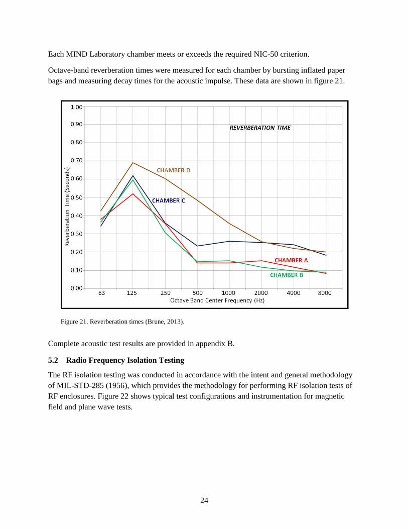
Each MIND Laboratory chamber meets or exceeds the required NIC-50 criterion.
Octave-band reverberation times were measured for each chamber by bursting inflated paper
bags and measuring decay times for the acoustic impulse. These data are shown in figure 21.
Figure 21. Reverberation times (Brune, 2013).
Complete acoustic test results are provided in appendix B.
5.2 Radio Frequency Isolation Testing
The RF isolation testing was conducted in accordance with the intent and general methodology
of MIL-STD-285 (1956), which provides the methodology for performing RF isolation tests of
RF enclosures. Figure 22 shows typical test configurations and instrumentation for magnetic
field and plane wave tests.

25
Figure 22. MIND Laboratory: typical RF configurations and instrumentation. Panel A: loop antennas for
magnetic field tests; panel B: log periodic antennas for plane wave tests; panel C: Giga-tronics RF
signal generator; panel D: Hewlett-Packard spectrum analyzer. (U.S. Army photos by Ron Carty.)
For each frequency tested, a reference signal was established using a signal generator and a
matched set of antennas designed for each frequency band. Measurements were obtained with a
spectrum analyzer in an open part of the test area. After the reference level was achieved, the
transmit antenna and receive antenna were placed on opposite sides of the test point at the
prescribed spacing. The signal level received in this position, if any, was subtracted from the
reference signal resulting in the signal attenuation value. This procedure was repeated for 28
discrete test points and 6 doors for a total of 34 test locations, each tested at 13 frequencies.
These locations are shown in figure 23. All test locations were tested by scanning along the
entire wall section, space permitting; all penetrations in the vicinity of a test location were
scanned. Doors were tested by scanning around the perimeter of the door and frame.
Figure 24 and table 3 show the results of the RF isolation tests. Data were averaged over the 34
test locations. Complete test results are shown in the test report in appendix C.

26
Figure 23. RF test measurement locations.
Figure 24. RF isolation test data, compared to required performance. (E = electric field;
M = magnetic field; PW = plane wave field.) Error bars = ±1 standard deviation.
27
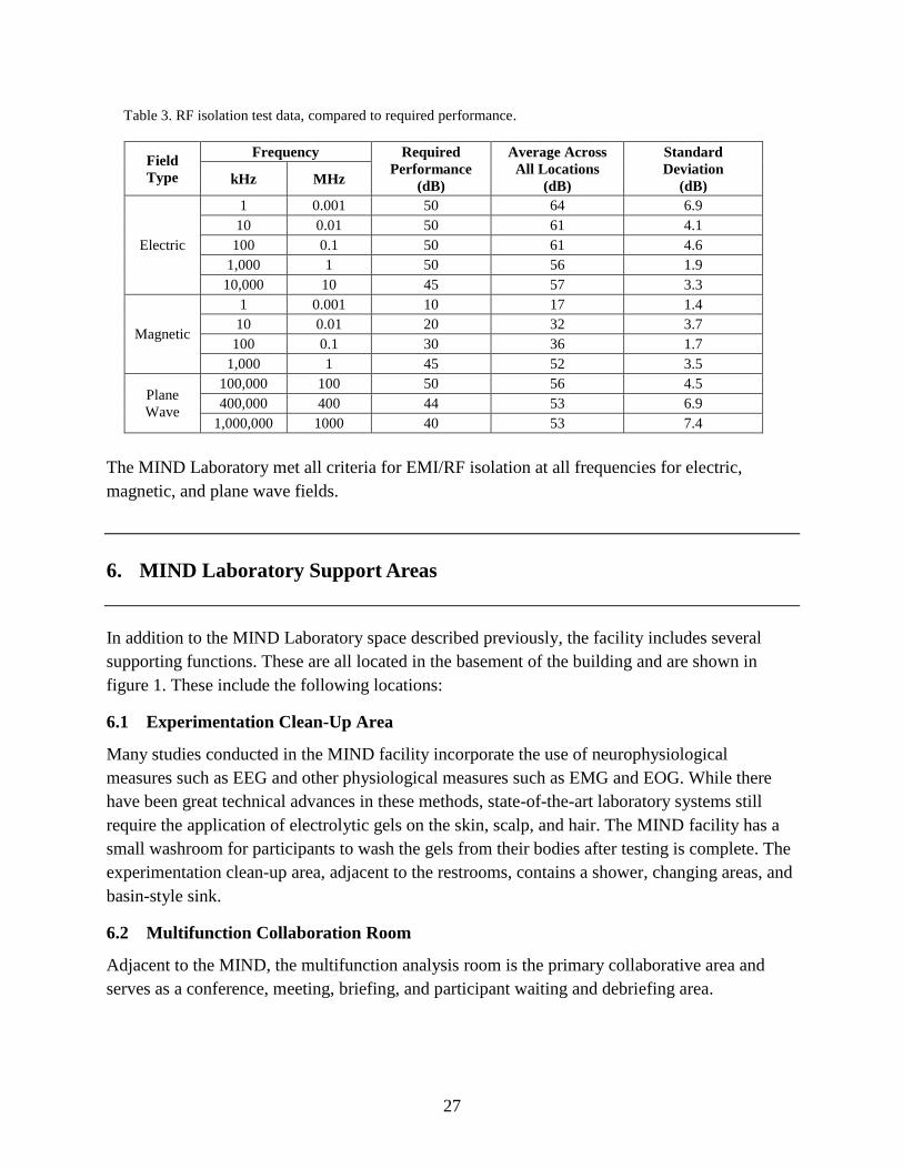
Table 3. RF isolation test data, compared to required performance.
Field
Type
Frequency Required
Performance
(dB)
Average Across
All Locations
(dB)
Standard
Deviation
(dB) kHz MHz
Electric
1 0.001 50 64 6.9
10 0.01 50 61 4.1
100 0.1 50 61 4.6
1,000 1 50 56 1.9
10,000 10 45 57 3.3
Magnetic
1 0.001 10 17 1.4
10 0.01 20 32 3.7
100 0.1 30 36 1.7
1,000 1 45 52 3.5
Plane
Wave
100,000 100 50 56 4.5
400,000 400 44 53 6.9
1,000,000 1000 40 53 7.4
The MIND Laboratory met all criteria for EMI/RF isolation at all frequencies for electric,
magnetic, and plane wave fields.
6. MIND Laboratory Support Areas
In addition to the MIND Laboratory space described previously, the facility includes several
supporting functions. These are all located in the basement of the building and are shown in
figure 1. These include the following locations:
6.1 Experimentation Clean-Up Area
Many studies conducted in the MIND facility incorporate the use of neurophysiological
measures such as EEG and other physiological measures such as EMG and EOG. While there
have been great technical advances in these methods, state-of-the-art laboratory systems still
require the application of electrolytic gels on the skin, scalp, and hair. The MIND facility has a
small washroom for participants to wash the gels from their bodies after testing is complete. The
experimentation clean-up area, adjacent to the restrooms, contains a shower, changing areas, and
basin-style sink.
6.2 Multifunction Collaboration Room
Adjacent to the MIND, the multifunction analysis room is the primary collaborative area and
serves as a conference, meeting, briefing, and participant waiting and debriefing area.
28
6.3 Linux Laboratory
This space is used for collaborative computing, with multiple Linux-based high-end
workstations. These workstations provide a common space for neuroscience researchers and
collaborators to share code, data, and analytical methods, and for them to collaborate on data
analysis. To facilitate data sharing of large-scale datasets, these Linux-based workstations
operate via a central fileserver. Most analyses utilize Mathwork’s Matlab* and other supporting
software, with code-sharing, visualization, and collaboration facilitated by the use of large-screen
displays.
7. Conclusion
The MIND Laboratory research space was fabricated and installed over a 20-month period. The
research facility meets all specified performance requirements and should fully meet the needs of
ARL’s neuroscience research for many years to come.
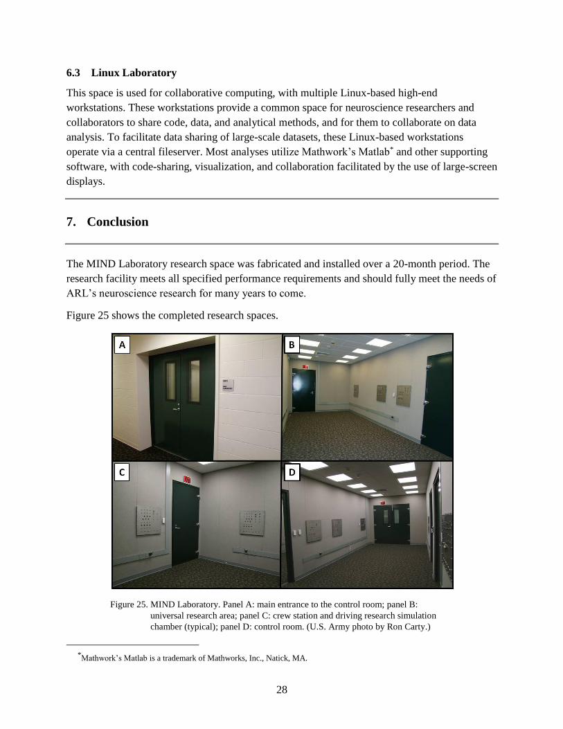
Figure 25 shows the completed research spaces.
Figure 25. MIND Laboratory. Panel A: main entrance to the control room; panel B:
universal research area; panel C: crew station and driving research simulation
chamber (typical); panel D: control room. (U.S. Army photo by Ron Carty.)
*Mathwork’s Matlab is a trademark of Mathworks, Inc., Natick, MA.

29
8. References
ASTM Standard E413. Classification for Rating Sound Insulation, ASTM International, West
Conshohocken, PA, 2010; DOI: 10.1520/E0413-10.
ASTM Standard E90. Standard Test Method for Laboratory Measurement of Airborne Sound
Transmission Loss of Building Partitions and Elements, ASTM International, West
Conshohocken, PA, 2009; DOI: 10.1520/E90-09.
Brune, B. G. MIND Lab Noise Transmission Test Report; Brune Consulting, LLC.: Towson,
MD, 2013.
DA PAM 420–11. Facilities Engineering, Project Definition and Work Classification;
Department of the Army: Washington, DC, 2010.
MIL-STD-285, 1956. Attenuation Measurements for Enclosures, Electromagnetic Shielding, for
Electronic Test Purposes, Method of 1956.
Noise Barriers, LLC. Typical Installation Details, Project # 010-7251, Libertyville, IL, 2011.
Oie, K. S.; McDowell, K.; Metcalfe, J.; Hairston, W. D.; Kerrick, S.; Lee, T.; Makeig. S. The
Cognition and Neuroergonomics (CaN) Collaborative Technology Alliance (CTA): Scientific
Vision, Approach, and Translational Paths; ARL-SR-0252; U.S. Army Research
Laboratory: Aberdeen Proving Ground, MD, 2012.

30
INTENTIONALLY LEFT BLANK.

31
Appendix A. Fiberglass Panel Test Report
This appendix appears in its original form, without editorial change.

32

33

34
35

36
INTENTIONALLY LEFT BLANK.

37
Appendix B. APG MIND Lab Noise Transmission Test Report
This appendix appears in its original form, without editorial change.

38
APG MIND LAB
NOISE TRANSMISSION TEST DOCUMENTATION
February 12, 2013

39
40
APG MIND LAB
NOISE TRANSMISSION TEST DOCUMENTATION
February 12, 2013
Enclosure 1
TechStar Industries
February 26, 2013

41
Figure 1 – Test Instrumentation in Chamber C
Table 1 – Test Instrumentation Descriptions
Item Instrument Manufacturer Model Serial Calibration
1 Sound Analyzer Norsonic Type N-140 1403256 12-19-2012
2 Microphone Norsonic Type N-1225 96065 12-19-2012
3 Microphone Pre Amp Norsonic Type N-1209 13469 12-19-2012
4 Dodecahedron Loudspeaker Norsonic N-270 27031833 NA
5 Amplifier Norsonic N-260 2803920 NA
42
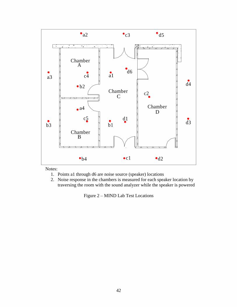
Notes:
1. Points a1 through d6 are noise source (speaker) locations
2. Noise response in the chambers is measured for each speaker location by
traversing the room with the sound analyzer while the speaker is powered
Figure 2 – MIND Lab Test Locations
A
B
C
D
a1
a2
a3
a4
b1
b2
b3
b4 c1 d2
c2
c3 d5
d6
d1
Chamber
Chamber
Chamber
Chamber
d3
d4
c4
c5

43
Table 2 – MIND Lab Noise Test Sequence
Location Run # (Cool/Heat) Loc Run # Loc Run # Loc Run # Loc Run #
A 1/77 A 20 B 54 C 37 D 49
a1 a1 18 b1 53 c1 32 d1 48
a2 a2 b2 c2 d2
a3 a3 b3 c3 d3
a4 a4 b4 c4 d4
B 2/78 A 24 B 56 c5 d5
b1 a1 b1 C 61 d6
b2 a2 22 b2 55 c1 D 39
b3 a3 b3 c2 60 d1
b4 a4 b4 c3 d2 38
C 3/79 A 26 B 28 c4 d3
c1 a1 b1 c5 d4
c2 a2 b2 C 51 d5
c3 a3 25 b3 27 c1 d6
c4 a4 b4 c2 D 41
c5 A 58 B 30 c3 50 d1
D 4/80 a1 b1 c4 d2
d1 a2 b2 c5 d3 40
d2 a3 b3 C 63 d4
d3 a4 57 b4 29 c1 d5
d4 c2 d6
d5 c3 D 43
d6 c4 62 d1
c5 d2
C 65 d3
c1 d4 42
c2 d5
c3 d6
c4 D 45
c5 64 d1
d2
d3
d4
d5 44
Denotes Source (Speaker Locations) d6
D 47
d1
d2
d3
d4
d5
d6 46
Source OnSource Off Source On Source On Source On

44
Table 3 – Chamber A Noise Reduction
Figure 3 – Chamber A NIC Result
MEASURED AIRBORNE NOISE REDUCTION IN OCTAVE BANDS
PROJECT: APG Mind Lab
DESCRIPTION: Leq, Equivalent Airborne Noise Levels (dB re: 20 microPascals)
OB RUN NUMBER
Cntr Freq 18 20 22 24 25 26 57 58 18-20 22-24 25-26 57-58 Avg Spec
8
16
32 72 57 77 50 79 58 81 68 15 27 20 13 19
63 92 69 91 59 97 71 92 74 22 32 25 18 24
125 107 76 106 57 108 72 107 72 31 50 36 34 38 25
250 109 64 108 52 108 66 108 66 44 56 42 42 46 37
500 97 47 102 40 101 50 97 46 50 62 51 50 53 48
1000 94 36 97 29 97 39 92 33 58 68 57 59 61 55
2000 96 33 96 25 98 33 92 30 63 71 65 62 65 59
4000 94 30 97 21 96 27 94 29 64 76 69 65 68 60
8000 78 19 80 17 80 19 75 19 59 63 61 56 60 58
Meas Loc a1 A a2 A a3 A a4 A Wall 1 Wall 2 Wall 3 Wall 4
NOISE REDUCTION
Chamber A
30
35
40
45
50
55
60
65
70
10
0
12
5
16
0
20
0
25
0
31
5
40
0
50
0
63
0
80
0
10
00
12
50
16
00
20
00
25
00
31
75
40
00
50
00
Rela
tiv
e S
ou
nd
In
sula
tio
n, d
B
One-Third Octave Band Center Frequency (Hz)
NIC 58
Wall Average
Noise Reduction
CHAMBER A
NIC 50

45
Table 4 – Chamber B Noise Reduction
Figure 4 – Chamber B NIC Result
MEASURED AIRBORNE NOISE REDUCTION IN OCTAVE BANDS
PROJECT: APG Mind Lab
DESCRIPTION: Leq, Equivalent Airborne Noise Levels (dB re: 20 microPascals)
OB
Cntr Freq 53 54 55 56 27 28 29 30 53-54 55-56 27-28 29-30 Avg Spec
8
16
32 79 60 81 68 79 61 77 58 18 12 18 19 17
63 88 69 93 76 90 70 92 65 19 17 20 28 21
125 105 72 105 71 108 68 107 65 33 34 40 42 37 25
250 106 64 107 66 108 63 108 64 42 40 44 44 43 37
500 96 47 96 48 98 50 100 52 49 48 49 48 49 48
1000 91 38 91 33 96 43 96 41 54 58 52 56 55 55
2000 92 36 92 30 96 35 97 35 56 61 61 62 60 59
4000 93 33 92 29 97 31 97 31 60 63 66 66 64 60
8000 74 23 73 19 80 19 79 19 51 54 61 60 57 58
Meas Loc b1 B b2 B b3 B b4 B Wall 1 Wall2 Wall 3 Wall 4
NOISE REDUCTION
Chamber B
RUN NUMBER
30
35
40
45
50
55
60
65
70
10
0
12
5
16
0
20
0
25
0
31
5
40
0
50
0
63
0
80
0
10
00
12
50
16
00
20
00
25
00
31
75
40
00
50
00
Rela
tiv
e S
ou
nd
In
sula
tio
n, d
B
One-Third Octave Band Center Frequency (Hz)
NIC 54
Wall Average
Noise Reduction
CHAMBER B

46
Table 5 – Chamber C Noise Reduction
Figure 5 – Chamber C NIC Result
MEASURED AIRBORNE NOISE REDUCTION IN OCTAVE BANDS
PROJECT: APG Mind Lab
DESCRIPTION: Leq, Equivalent Airborne Noise Levels (dB re: 20 microPascals)
OB
Cntr Freq 32 37 60 61 50 51 62 63 64 65 32-37 60-61 50-51 62-63 64-65 Avg Spec
8
16
32 74 57 78 58 79 54 79 54 79 57 17 20 25 25 22 22
63 92 65 92 69 94 65 95 69 95 71 27 23 29 25 24 26
125 106 70 105 75 108 69 107 73 106 71 36 30 38 34 35 35 25
250 106 69 106 69 109 69 108 65 106 64 37 37 41 43 42 40 37
500 97 56 95 52 99 56 97 46 95 48 42 44 43 52 48 46 48
1000 92 48 91 42 96 50 93 35 90 42 44 49 46 58 49 49 55
2000 93 45 91 39 97 48 93 33 91 38 49 53 49 61 53 53 59
4000 94 42 93 38 98 44 94 31 91 36 52 55 54 63 55 56 60
8000 76 24 74 22 80 25 76 23 72 23 52 52 55 53 50 52 58
Meas Loc c1 C c2 C c3 C c4 C c5 C 1 2 3 4 5
NOISE REDUCTION
Chamber C
RUN NUMBER
Wall Segment
30
35
40
45
50
55
60
65
70
10
0
12
5
16
0
20
0
25
0
31
5
40
0
50
0
63
0
80
0
10
00
12
50
16
00
20
00
25
00
31
75
40
00
50
00
Rela
tiv
e S
ou
nd
In
sula
tio
n, d
B
One-Third Octave Band Center Frequency (Hz)
NIC 50
Wall Average
Noise Reduction
CHAMBER C

47
Table 6 – Chamber D Noise Reduction
Figure 6 – Chamber D NIC Result
MEASURED AIRBORNE NOISE REDUCTION IN OCTAVE BANDS
PROJECT: APG Mind Lab
DESCRIPTION: Leq, Equivalent Airborne Noise Levels (dB re: 20 microPascals)
OB
Cntr Freq 48 49 38 39 40 41 42 43 44 45 46 47 48-49 38-39 40-41 42-43 44-45 46-47 Avg Spec
8
16
32 80 64 76 57 77 64 77 63 78 53 77 60 16 18 14 14 24 17 17
63 92 72 92 73 95 75 95 76 94 65 92 71 20 18 20 19 29 21 21
125 105 73 106 71 107 70 108 72 108 63 105 73 32 35 36 35 44 32 36 25
250 106 68 107 66 108 67 106 66 106 57 106 68 38 41 41 40 49 38 41 37
500 95 48 99 54 99 51 100 54 101 42 96 50 47 44 48 46 58 45 48 48
1000 91 38 95 46 95 40 97 45 96 32 92 42 53 49 54 52 63 50 54 55
2000 93 35 95 44 96 39 97 38 97 29 92 40 57 51 56 60 68 52 57 59
4000 92 32 96 39 96 33 97 36 96 26 94 36 60 57 63 61 70 57 61 60
8000 73 20 78 22 78 20 79 28 77 20 75 21 53 55 58 52 57 54 55 58
Meas Loc d1 D d2 D d3 D d4 D d5 D d6 D 1 2 3 4 5 6
NOISE REDUCTION
Chamber D
RUN NUMBER
Wall Segment
30
35
40
45
50
55
60
65
70
10
0
12
5
16
0
20
0
25
0
31
5
40
0
50
0
63
0
80
0
10
00
12
50
16
00
20
00
25
00
31
75
40
00
50
00
Rela
tiv
e S
ou
nd
In
sula
tio
n, d
B
One-Third Octave Band Center Frequency (Hz)
NIC 53
Wall Average
Noise Reduction
CHAMBER D

48
Figure 7 – Chamber Measured Reverberation Times
0.00
0.10
0.20
0.30
0.40
0.50
0.60
0.70
0.80
0.90
1.00
63 125 250 500 1000 2000 4000 8000
Rev
erb
erati
on
Tim
e, s
eco
nd
s
Octave Band Center Frequency, Hz
Chamber A
Chamber C
Chamber B
Chamber D
REVERBERATION TIME (SECONDS)

49
Appendix C. Radio Frequency Isolation Report
The contents of the appendix have been altered only to remove sensitive information.

50
51
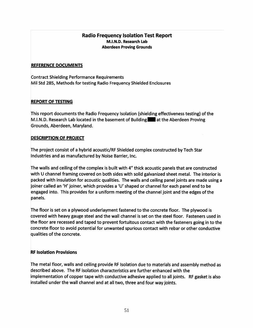
Radio Frequency Isolation Test Report M.I.N.O. Research Lab
Aberdeen Proving Grounds
REFERENCE DOCUMENTS
Contract Shielding Performance Requirements Mil Std 285, Methods for testing Radio Frequency Shielded Enclosures
REPORT OF TESTING
This report documents the Radio Frequency Isolation {shielding effectiveness testing) of the M.I.N.D. Research lab located in the basement of Building- at the Aberdeen Proving Grounds, Aberdeen, Maryland.
DESCRIPTION OF PROJECT
The project consist of a hybrid acoustic/RF Shielded complex constructed by Tech Star Industries and as manufactured by Noise Barrier, Inc.
The walls and ceiling of the complex is built with 4" thick acoustic panels that are constructed with U channel framing covered on both sides with solid galvanized sheet metal. The interior is packed with insulation for acoustic qualities. The walls and ceiling panel joints are made using a joiner called an 'H' joiner, which provides a 'U' shaped or channel for each panel end to be engaged into. This provides for a uniform meeting of the channel joint and the edges of the panels.
The floor is set on a plywood underlayment fastened to the concrete floor. The plywood is covered with heavy gauge steel and the wall channel is set on the steel floor. Fasteners used in the floor are recessed and taped to prevent fortuitous contact with the fasteners going in to the concrete floor to avoid potential for unwanted spurious contact with rebar or other conductive qualities of the concrete.
RF Isolation Provisions
The metal floor, walls and ceiling provide RF Isolation due to materials and assembly method as described above. The RF isolation characteristics are further enhanced with the implementation of copper tape with conductive adhesive applied to all joints. RF gasket is also installed under the wall channel and at all two, three and four way joints.

52
53
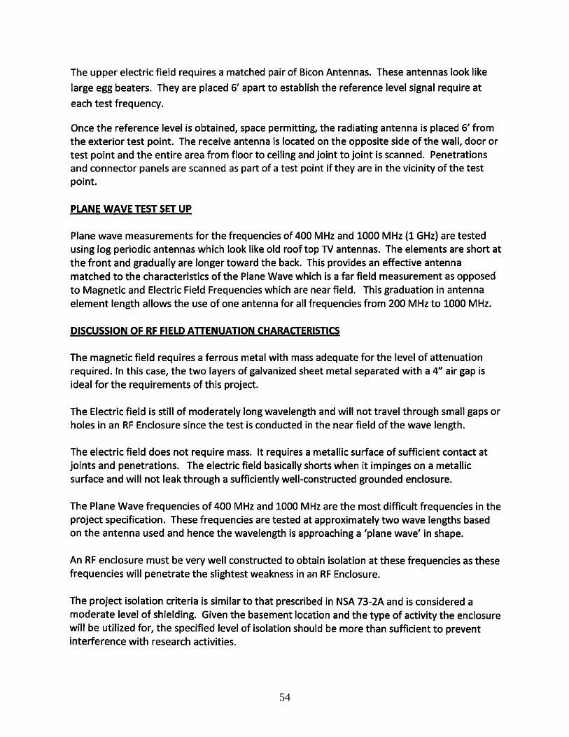
54
55
*Figure 1 is not included. See figure 23 in section 5.2 of the report.
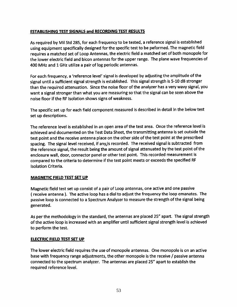
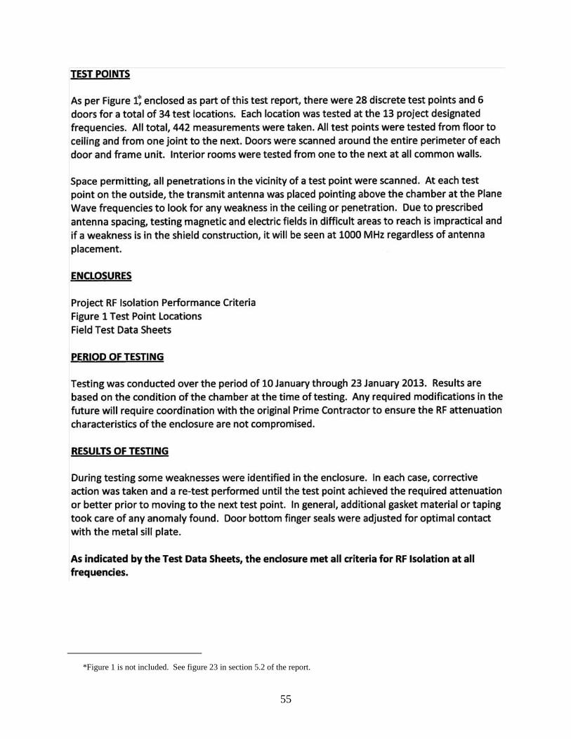
TEST PQINTS
As per Figure 1~ enclosed as part of this test report, there were 28 discrete test points and 6 doors for a total of 34 test locations. Each location was tested at the 13 project designated
frequencies. All total, 442 measurements were taken. All test points were tested from floor to
ceiling and from one joint to the next. Doors were scanned around the entire perimeter of each door and frame unit. Interior rooms were tested from one to the next at all common walls.
Space permitting, all penetrations in the vicinity of a test point were scanned. At each test point on the outside, the transmit antenna was placed pointing above the chamber at the Plane
Wave frequencies to look for any weakness in the ceiling or penetration. Due to prescribed antenna spacing, testing magnetic and electric fields in difficult areas to reach is impractical and
if a weakness is in the shield construction, it will be seen at 1000 MHz regardless of antenna placement.
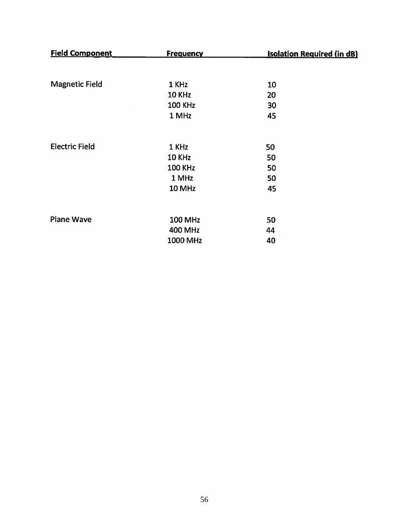
ENCLOSURES
Project RF Isolation Performance Criteria Figure 1 Test Point locations Field Test Data Sheets
PERIOD OF TESTING
Testing was conducted over the period of 10 January through 23 January 2013. Results are based on the condition of the chamber at the time of testing. Any required modifications in the
future will require coordination with the original Prime Contractor to ensure the RF attenuation characteristics of the enclosure are not compromised.
RESULTS OF TESTING
During testing some weaknesses were identified in the enclosure. In each case, corrective action was taken and a re-test performed until the test point achieved the required attenuation
or better prior to moving to the next test point. In general, additional gasket material or taping took care of any anomaly found. Door bottom finger seals were adjusted for optimal contact with the metal sill plate.
As indicated by the Test Data Sheets, the endosure met all aiteria for RF Isolation at all frequencies.
56

57

58

59

60
TEST DATA SHEET
location: Mind lab APG
Test Engineer: Henry Osgood Assisted by: __ .......:.N:L/.:...:A ________ _
Frequency: (E) 10 MHz Required Attentuation: __ ....;;4;:.:=5::::d.=.b ____ _
Test Point Ref Lvl Measured lvl Attentuation 1 D ext wall 60 0 55 2 D ext wall 60 0 60 3 D ext wall 60 0 60 4 D ext wall 60 0 60 5 D ext wall 60 0 60 6 D ext wall 60 0 60 7 D ext wall 60 0 60 8 D ext wall 60 0 60 9 C-A Ext Joint 60 5 55 10 A Ext wall 60 0 60 11 A Ext wall 60 0 60 12 A Ext wall 60 0 60 13 A Ext wall 60 0 60 14 A Ext wall 60 0 60 15 A Ext wall 60 0 60 16 B outside 60 0 60 17 B outside 60 0 60 18 B outside 60 0 60 19 B outside 60 0 60 20 B outside 60 0 60 21 B outside 60 0 60 22 C-D ext joint 60 5 55 23 C-D Common wall 60 5 55 24 C-D Common wall 60 5 55 25 C-D Common wall 60 5 55
26 B-C wall 60 5 55
27 A-B wall 60 5 55
28 A-C wall 60 5 55
D-1 Chamber D door 60 5 55
D-2 C-D door 60 8 52
D-3 Chamber C door 60 10 50
D-4 Chamber C door 60 10 50
D-5 Chamber A door 60 8 52
D-6 Chamber B door 60 5 55

61
TEST DATA SHEET
Location: Mind Lab APG
Test Engineer: Henry Osgood Assisted by: __ __,_N=I.:....:A'----------
Frequency: (E) 1 MHz Required Attentuation: __ _,S~O:.::d.::.b ____ _
Test Point Ref Lvl Measured Lvl Attentuat ion 1 D ext wall 60 0 50+ 2 D ext wall 60 0 50+ 3 D ext wall 60 0 50+ 4 D ext wall 60 0 50+ 5 D ext wall 60 0 50+ 6 D ext wall 60 0 50+ 7 D ext wall 60 0 50+ 8 D ext wall 60 0 50+ 9 C-A Ext Joint 60 0 50+ 10 A Ext wall 60 0 50+ 11 A Ext wall 60 0 50+ 12 A Ext wall 60 0 50+ 13 A Ext wall 60 0 50+ 14 A Ext wall 60 0 SO+ 15 A Ext wall 60 0 50+ 16 B outside 60 0 50+ 17 B outside 60 0 50+ 18 B outside 60 0 50+ 19 B outside 60 0 50+ 20 B outside 60 0 50+ 21 8 outside 60 0 50+
22 C-D ext joint 60 0 50+ 23 C-D Common wall 60 5 55 24 C-D Common wall 60 5 55 25 C-D Common wall 60 5 55
26 B-C wall 60 5 55
27 A-8 wall 60 5 55
28 A-C wall 60 5 55
D-1 Chamber D door 60 5 55
D-2 C-D door 60 5 55 D-3 Chamber C door 60 5 55
D-4 Chamber C door 60 5 55
D-5 Chamber A door 60 0 60
D-6 Chamber B door 60 0 60

62
TEST DATA SHEET
Location: Mind Lab APG
Test Engineer: Henrv Osgood Assisted by: __ __!N.!J./.:::.A!..._ _______ _
Frequency: (E) 10 KHz Required Attentuation: __ _,S:..::O::.:d~b ____ _
Test Point Ref Lvl Measured Lvl Attentuation
1 D ext wall 65 5 60
2 D ext wall 65 0 65
3 D ext wall 65 0 65 4 D ext wall 65 0 65
5 D ext wall 65 0 65
6 D ext wall 65 0 65
7 D ext wall 65 0 65
8 D ext wall 65 8 57 9 C-A Ext Joint 65 10 55 10 A Ext wall 65 0 65 11 A Ext wall 65 0 65
12 A Ext wall 65 0 65
13 A Ext wall 65 0 65 14 A Ext wall 65 0 65 15 A Ext wall 65 0 65
16 8 outside 65 0 65
17 8 outside 65 0 65 18 8 outside 65 0 65
19 8 outside 65 0 65
20 8 outside 65 0 65 21 8 outside 65 8 57
22 C-D ext joint 65 10 55 23 C-D Common wall 65 5 60 24 C-D Common wall 65 5 60
25 C-D Common wall 65 5 60
26 8-C wall 65 5 60
27 A-8 wall 65 5 60
28 A-C wall 65 5 60 D-1 Chamber D door 65 8 57
D-2 C-D door 65 10 55
D-3 Chamber C door 65 12 53
D-4 Chamber C door 65 12 53
D-5 Chamber A door 65 5 60
D-6 Chamber 8 door 65 5 60
63
TEST DATA SHEET
location: Mind lab APG
Test Engineer: Henry Osgood Assisted by: __ _.:,N;!L/_,_,A'----------
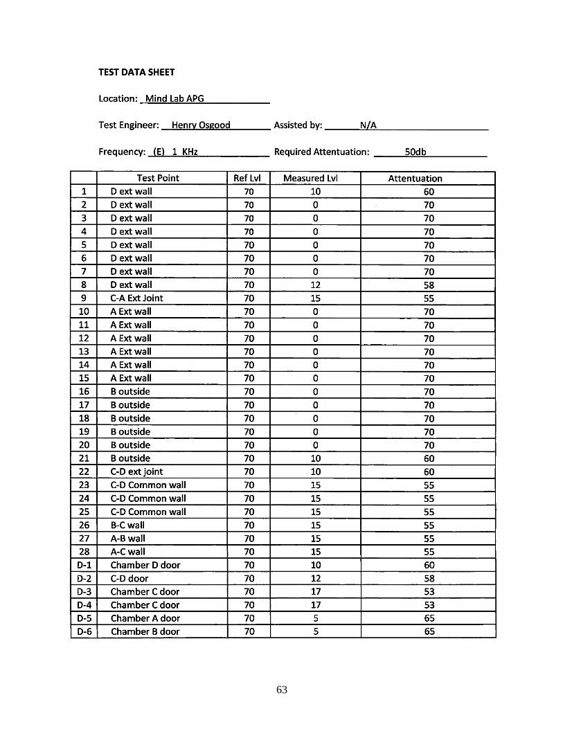
Frequency: (E) 1 KHz Required Attentuation: __ _,5~0~d~b ____ _
Test Point Ref lvl Measured lvl Attentuation 1 D ext wall 70 10 60 2 D ext wall 70 0 70 3 D ext wall 70 0 70 4 D ext wall 70 0 70 5 D ext wall 70 0 70 6 D ext wall 70 0 70 7 D ext wall 70 0 70 8 D ext wall 70 12 58 9 C-A Ext Joint 70 15 55 10 A Ext wall 70 0 70 11 A Ext wall 70 0 70 12 A Ext wall 70 0 70 13 A Ext wall 70 0 70 14 A Ext wall 70 0 70 15 A Ext wall 70 0 70 16 B outside 70 0 70 17 B outside 70 0 70 18 B outside 70 0 70 19 B outside 70 0 70 20 B outside 70 0 70 21 B outside 70 10 60 22 C-D ext joint 70 10 60 23 C-D Common wall 70 15 55
24 C-D Common wall 70 15 55 25 C-D Common wall 70 15 55 26 B-C wall 70 15 55 27 A-B wall 70 15 55 28 A-C wall 70 15 55 D-1 Chamber D door 70 10 60 D-2 C-D door 70 12 58 D-3 Chamber C door 70 17 53 D-4 Chamber C door 70 17 53 D-5 Chamber A door 70 5 65 D-6 Chamber B door 70 5 65

64
TEST DATA SHEET
Location: Mind Lab APG
Test Engineer: Henry Osgood Assisted by: --~N~/"-=-A:....._ _______ _
Frequency: (M) 1 KHz Required Attentuation: ___ 4=5=d=b ____ _
Test Point Ref Lvl Measured Lvl Attentuation
1 D ext wall 55 5 so 2 D ext wall 55 0 55
3 D ext wall 55 0 55
4 D ext wall 55 0 55
5 D ext wall 55 0 55
6 D ext wall 55 0 55
7 D ext wall 55 0 55
8 D ext wall 55 5 so 9 C-A Ext Joint 55 5 so 10 A Ext wall 55 0 55 11 A Ext wall 55 0 55 12 A Ext wall 55 0 55 13 A Ext wall 55 0 55
14 A Ext wall 55 0 55
15 A Ext wall 55 0 55
16 B outside 55 0 55 17 B outside 55 0 55 18 B outside 55 0 55 19 B outside 55 0 55
20 B outside 55 0 55
21 B outside 55 3 52
22 C-D ext joint 55 4 51 23 C-D Common wall 55 8 47 24 C-D Common wall 55 6 49 25 C-D Common wall 55 8 47 26 B-C wall 55 7 48 27 A-Bwall 55 8 47 28 A-C wall 55 8 47
D-1 Chamber D door 55 5 so D-2 C-D door 55 8 47 D-3 Chamber C door 55 10 45 D-4 Chamber C door 55 8 47 D-5 Chamber A door 55 5 50 D-6 Chamber B door 55 5 50

65
TEST DATA SHEET
location: Mind lab APG
Test Engineer: Henry Osgood Assisted by: __ ___.N:...:./...,_A..:..-_______ _
Frequency: (M) 100 KHz Required Attentuation: __ ......=.;30~d::..:b::....._ ___ _
Test Point Ref lvl Measured lvl Attentuation
1 D ext wall 40 5 35
2 D ext wall 40 >3 37
3 D ext wall 40 >3 37
4 D ext wall 40 >3 37
5 D ext wall 40 >3 37
6 D ext wall 40 >3 37
7 D ext wall 40 >3 37
8 D ext wall 40 >3 37 9 C-A Ext Joint 40 5 35 10 A Ext wall 40 >3 37
11 A Ext wall 40 >3 37
12 A Ext wall 40 >3 37
13 A Ext wall 40 >3 37
14 A Ext wall 40 >3 37
15 A Ext wall 40 >3 37 16 B outside 40 >3 37 17 B outside 40 >3 37 18 B outside 40 >3 37
19 B outside 40 >3 37
20 B outside 40 >3 37
21 B outside 40 5 40 22 C-D ext joint 40 7 33 23 C-D Common wall 40 >6 34 24 C-D Common wall 40 >6 34
25 C-D Common wall 40 >6 34 26 B-Cwall 40 >6 34 27 A-B wall 40 >6 34
28 A-C wall 40 >6 34 D-1 Chamber D door 40 5 35 0-2 C-D door 40 8 32 D-3 Chamber C door 40 7 33 D-4 Chamber C door 40 6 34 0-5 Chamber A door 40 >5 35
0-6 Chamber B door 40 >5 35
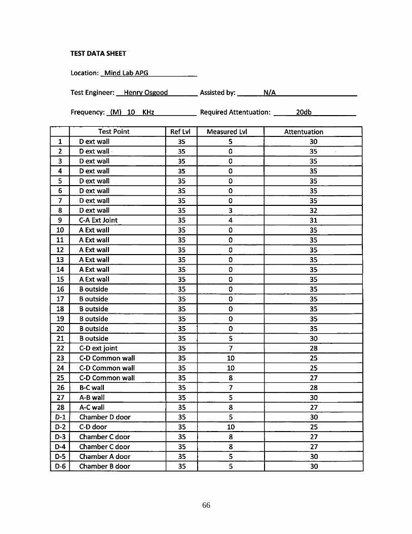
66
TEST DATA SHEET
Location: Mind Lab APG
Test Engineer: Henry Osgood Assisted by: __ ____:N~/:.!..A=------------
Frequency: (M) 10 KHz Required Attentuation: __ _,2=0=d=-b ____ _
Test Point Reflvl Measured Lvl Attentuation
1 D ext wall 35 5 30 2 D ext wall · 35 0 35
3 D ext wall 35 0 35
4 D ext wall 35 0 35 5 D ext wall 35 0 35 6 D ext wall 35 0 35
7 D ext wall 35 0 35 8 D ext wall 35 3 32
9 C-A Ext Joint 35 4 31 10 A Ext wall 35 0 35 11 A Ext wall 35 0 35 12 A Ext wall 35 0 35 13 A Ext wall 35 0 35 14 A Ext wall 35 0 35
15 A Ext wall 35 0 35
16 B outside 35 0 35 17 B outside 35 0 35 18 B outside 35 0 35 19 B outside 35 0 35
20 B outside 35 0 35 21 B outside 35 5 30 22 C-D ext joint 35 7 28
23 C-D Common wall 35 10 25
24 C-D Common wall 35 10 25
25 C-D Common wall 35 8 27 26 B-C wall 35 7 28
27 A-B wall 35 5 30 28 A-C wall 35 8 27 D-1 Chamber D door 35 5 30 D-2 C-D door 35 10 25
D-3 Chamber C door 35 8 27
D-4 Chamber C door 35 8 27 D-5 Chamber A door 35 5 30 D-6 Chamber 8 door 35 5 30

67
TEST DATA SHEET
Location: Mind Lab APG
Test Engineer: Henrv Osgood Assisted by: __ ____:N:.:.~I..:.A.:...... _______ _
Frequency: (M) 1 KHz Required Attentuation: ---=10=d=b=-------
Test Point Ref Lvl Measured Lvl Attentuation
1 D ext wall 18 3 15
2 D ext wall 18 0 18
3 D ext wall 18 0 18
4 D ext wall 18 0 18
5 D ext wall 18 0 18
6 D ext wall 18 0 18
7 D ext wall 18 0 18
8 D ext wall 18 4 14
9 C-A Ext Joint 18 5 13
10 A Ext wall 18 0 18
11 A Ext wall 18 0 18
12 A Ext wall 18 0 18
13 A Ext wall 18 0 18
14 A Ext wall 18 0 18
15 A Ext wall 18 0 18
16 B outside 18 0 18
17 B outside 18 0 18
18 B outside 18 0 18
19 B outside 18 0 18
20 B outside 18 0 18 21 B outside 18 2 16
22 C-D ext joint 18 0 18
23 C-D Common wall 18 >2 16
24 C-D Common wall 18 >2 16 25 C-D Common wall 18 >2 16
26 B-C wall 18 >2 16
27 A-B wall 18 >2 16
28 A-C wall 18 >2 16
D-1 Chamber D door 18 0 18 D-2 C-D door 18 >3 15 D-3 Chamber C door 18 >3 15 D-4 Chamber C door 18 >3 15
0-5 Chamber A door 18 0 18
0-6 Chamber B door 18 0 18

68

NO. OF NO. OF
COPIES ORGANIZATION COPIES ORGANIZATION
69
1 DEFENSE TECHNICAL
(PDF) INFORMATION CTR
DTIC OCA
1 DIRECTOR
(PDF) US ARMY RESEARCH LAB
IMAL HRA
1 DIRECTOR
(PDF) US ARMY RESEARCH LAB
RDRL CIO LL
1 GOVT PRINTG OFC
(PDF) A MALHOTRA
1 ARMY RSCH LABORATORY – HRED
(PDF) RDRL HRM C A DAVISON
320 MANSCEN LOOP STE 115
FORT LEONARD WOOD MO 65473
1 ARMY RSCH LABORATORY – HRED
(PDF) RDRL HRM D
T DAVIS
BLDG 5400 RM C242
REDSTONE ARSENAL AL 35898-7290
1 ARMY RSCH LABORATORY – HRED
(PDF) RDRL HRS EA DR V J RICE
BLDG 4011 RM 217
1750 GREELEY RD
FORT SAM HOUSTON TX 78234-5002
1 ARMY RSCH LABORATORY – HRED
(PDF) RDRL HRM DG J RUBINSTEIN
BLDG 333
PICATINNY ARSENAL NJ 07806-5000
1 ARMY RSCH LABORATORY – HRED
(PDF) ARMC FIELD ELEMENT
RDRL HRM CH C BURNS
THIRD AVE BLDG 1467B RM 336
FORT KNOX KY 40121
1 ARMY RSCH LABORATORY – HRED
(PDF) AWC FIELD ELEMENT
RDRL HRM DJ D DURBIN
BLDG 4506 (DCD) RM 107
FORT RUCKER AL 36362-5000
1 ARMY RSCH LABORATORY – HRED
(PDF) RDRL HRM CK J REINHART
10125 KINGMAN RD BLDG 317
FORT BELVOIR VA 22060-5828
1 ARMY RSCH LABORATORY – HRED
(PDF) RDRL HRM AY M BARNES
2520 HEALY AVE
STE 1172 BLDG 51005
FORT HUACHUCA AZ 85613-7069
1 ARMY RSCH LABORATORY – HRED
(PDF) RDRL HRM AP D UNGVARSKY
POPE HALL BLDG 470
BCBL 806 HARRISON DR
FORT LEAVENWORTH KS 66027-2302
1 ARMY RSCH LABORATORY – HRED
(PDF) RDRL HRM AT J CHEN
12423 RESEARCH PKWY
ORLANDO FL 32826-3276
1 ARMY RSCH LABORATORY – HRED
(PDF) RDRL HRM AT C KORTENHAUS
12350 RESEARCH PKWY
ORLANDO FL 32826-3276
1 ARMY RSCH LABORATORY – HRED
(PDF) RDRL HRM CU B LUTAS-SPENCER
6501 E 11 MILE RD MS 284
BLDG 200A 2ND FL RM 2104
WARREN MI 48397-5000
1 ARMY RSCH LABORATORY – HRED
(PDF) FIRES CTR OF EXCELLENCE
FIELD ELEMENT
RDRL HRM AF C HERNANDEZ
3040 NW AUSTIN RD RM 221
FORT SILL OK 73503-9043
1 ARMY RSCH LABORATORY – HRED
(PDF) RDRL HRM AV W CULBERTSON
91012 STATION AVE
FORT HOOD TX 76544-5073
1 ARMY RSCH LABORATORY – HRED
(PDF) HUMAN RSRCH AND ENGRNG
DIRCTRT MCOE FIELD ELEMENT
RDRL HRM DW C CARSTENS
6450 WAY ST
BLDG 2839 RM 310
FORT BENNING GA 31905-5400

NO. OF NO. OF
COPIES ORGANIZATION COPIES ORGANIZATION
70
1 ARMY RSCH LABORATORY – HRED
(PDF) RDRL HRM DE A MARES
1733 PLEASONTON RD BOX 3
FORT BLISS TX 79916-6816
8 ARMY RSCH LABORATORY – HRED
(PDF) SIMULATION & TRAINING
TECHNOLOGY CENTER
RDRL HRT COL M CLARKE
RDRL HRT I MARTINEZ
RDRL HRT T R SOTTILARE
RDRL HRT B N FINKELSTEIN
RDRL HRT G A RODRIGUEZ
RDRL HRT I J HART
RDRL HRT M C METEVIER
RDRL HRT S B PETTIT
12423 RESEARCH PARKWAY
ORLANDO FL 32826
1 ARMY RSCH LABORATORY – HRED
(PDF) HQ USASOC
RDRL HRM CN R SPENCER
BLDG E2929 DESERT STORM DRIVE
FORT BRAGG NC 28310
1 ARMY G1
(PDF) DAPE MR B KNAPP
300 ARMY PENTAGON RM 2C489
WASHINGTON DC 20310-0300
16 TECHSTAR INDUSTRIES LLC
(15 HC R VON LANGE
1 PDF) 1124 S PACA ST
BALTIMORE MD 21230
2 TOMASZ LETOWSKI
(1 HC 2015 FAIRWOOD LANE
1 PDF) STATE COLLEGE PA 16803
ABERDEEN PROVING GROUND
136 DIR USARL
(125 HC RDRL HR
11 PDF) L ALLENDER (15 HC)
P FRANASZCZUK (10 HC)
K COSENZO
RDRL HRM
P SAVAGE-KNEPSHIELD
RDRL HRM AL
C PAULILLO
RDRL HRM B
C SAMMS
RDRL HRM C
L GARRETT
RDRL HRS
J LOCKETT (5 HC, 1 PDF)
RDRL HRS B
M LAFIANDRA
RDRL HRS C
K MCDOWELL (75 HC, 1 PDF)
RDRL HRS D
B AMREIN (10 HC, 1 PDF)
C STACHOWIAK (10 HC, 1 PDF)
RDRL HRS E
D HEADLEY