mitsubishi heavy industries - request for withholding root - nrc
TRANSCRIPT

March 6, 2013 Edmund Baumgartner, Esquire Corporate Counsel Mitsubishi Nuclear Energy Systems, Inc. 1001 19th Street North Suite 2000 Arlington, VA 22209 SUBJECT: MITSUBISHI HEAVY INDUSTRIES – REQUEST FOR WITHHOLDING ROOT
CAUSE ANALYSIS AND SUPPLEMENTAL TECHNICAL EVALUATION REPORT INFORMATION FROM PUBLIC DISCLOSURE
Dear Mr. Baumgartner:
In a February 14, 2013, letter to you, the NRC requested Mitsubishi Heavy Industries (MHI) to provide the MHI document “Root Cause Analysis Report for tube wear identified in the Unit 2 and Unit 3 Steam Generators of San Onofre Nuclear Generating Station,” and a redacted version of that document. You provided the requested documents in a letter (ML13057A012) dated February 25, 2013, and requested that certain information contained within the root cause analysis (RCA) and a supplemental technical evaluation report (STER), provided as a supplement to the RCA, be withheld from public disclosure pursuant to 10 CFR 2.390. Redacted versions of the RCA and STER documents were provided as Enclosures 4 and 6 of your letter, respectively (ML13057A013 and ML13057A014). Mitsubishi Heavy Industries stated in affidavits dated February 22, 2013, that it considered certain information within MHI’s RCA and STER to be proprietary and confidential and requested that the information be withheld from public disclosure pursuant to 10 CFR 2.390. A summary of the key points in the affidavits is as follows:
1. The information has been held in confidence by MHI.
2. The information describes unique design, manufacturing, experimental, and investigative information developed by MHI and not used in the exact form by any of MHI’s competitors.
3. The information was developed at significant cost to MHI.
4. The RCA is MHI’s organizational and programmatic root cause analysis, which is a sensitive, internal document of the type that MHI and others in the industry do not make public, because its purpose is to set forth a critical self-appraisal, with the benefit of hindsight, containing information and analyses that are the result of candid assessments performed by MHI.
5. MHI provided the information to the NRC voluntarily in confidence.
UNITED STATESNUCLEAR REGULATORY COMMISSION
REGION IV1600 EAST LAMAR BLVD
ARLINGTON, TEXAS 76011-4511

Mr. Edmund Baumgartner - 2 -
6. The information is not available in public sources and could not be gathered readily from other publicly available information.
7. Disclosure of the information would assist competitors of MHI in their design and manufacture of nuclear plant components without incurring the costs or risks associated with the design and manufacture of the subject component.
We have carefully reviewed your original redacted documents and the information contained in your request. Additionally, we held several discussions with you regarding the redacted information in your documents. Based on these discussions, MHI made some revisions to release additional information. Subsequently, MHI provided final revised versions of Enclosures 4 and 6 via e-mail on February 28 and March 6, 2013, respectively. We have concluded that the submitted information sought to be withheld in the final revised versions contains proprietary and confidential information. Therefore, the final revised versions of the submitted information marked as proprietary will be withheld from public disclosure pursuant to 10 C.F.R. 2.390(a)(4).
Withholding from public inspection shall not affect the right, if any, of persons properly and directly concerned to inspect the documents. If the need arises, we may send copies of this information to our consultants working in this area. We will, of course, ensure that the consultants have signed the appropriate agreements for handling proprietary information.
If the basis for withholding this information from public inspection should change in the future such that the information could then be made available for public inspection, you should promptly notify the NRC. You also should understand that the NRC may have cause to review this determination in the future if, for example, the scope of a Freedom of Information Act request includes your information. In all review situations, if the NRC makes a determination adverse to the above, you will be notified in advance of any public disclosure.
Sincerely, /RA/ Ryan E. Lantz, Chief SONGS Project Branch
Dockets: 50-361, 50-362 Licenses: NPF-10, NPF-15
Enclosures: MHI’s Revised Non-Proprietary RCA and STER

Mr. Edmund Baumgartner - 3 - Internal Distribution A. Howell, TM J. Andersen, DTM R. Lantz, C:SPB G. Werner, I&AL N. Taylor, SPE B. Parks, PE G. George, SRI J. Reynoso, RI K. Fuller, RC V. Dricks, PAO T. Rothschild, OGC R. Hall, NRR D. Broaddus, NRR E. Roach, NRO D. Dorman, NRR D. Merzke, OEDO J. Weil, OCA A. Powell, OCA
R:\_REACTORS\_SONGS\2013\Review of MHI and STER MNES 2-25-13 Letter_Agreement with Revised NonProp Reviews G:\ORA\SPB\MHI Letter and RCA and STER Enclosures ML13065A097 ADAMS: No Yes SUNSI Review Complete Reviewer Initials: GEW Publicly Available Non-Sensitive Non-publicly Available Sensitive
RIV:I&AL:SPB RC C:SPB GEWerner;dlf KDFuller RELantz /RA/ /RA/ /RA/
3/6/13 3/6/13 3/6/13
OFFICIAL RECORD COPY T=Telephone E=E-mail F=Fax

UES-20120254Rev.0 (1/64) Non-Proprietary
CONTENT
DESCRIPTION
FIGURE
Total
Dis
trib
utio
n
NP
CD
D
―SHEETS
―PAGES
REMARKS
ORDER No.
ITEM No.
2593015
7000
DATE
REFERENCE
-
-
0
Document No.
UES-20120254
Rev. No.
QUALITY ASSURANCE DEPARTMENT
1
Edison
(MNES)
SG
DS
1
NP
MD
1
NP
QA
S
1
CQ
CS
1
CHECKED BY
PREPARED BY
APPROVED BY
ISSUEDATE
DRAWN BY
―
MITSUBISHI HEAVY INDUSTRIES, LTD.
San Onofre Nuclear Generating Station, Unit 2 & 3
REPLACEMENT STEAM GENERATORS
Root Cause Analysis Report for tube wear
identified in the Unit 2 and Unit 3 Steam Generators of
San Onofre Nuclear Generating Station
PURCHASER
PAGES 64
― ―
CO
PY
2
Purchase Order No.
Specification No.
4500024051
SO23-617-01R3
1
SG
S
PM
1
E-R
oom
e

UES-20120254Rev.0 (2/64) Non-Proprietary
Revision History
Rev. Summary of Changes
Date
issued
Approved
By
Checked
by
Prepared
by
0 Original Issue See
Cover Page
See
Cover Page
See
Cover Page
See
Cover Page
UES-20120254 Rev.0 (3/64) Non-Proprietary
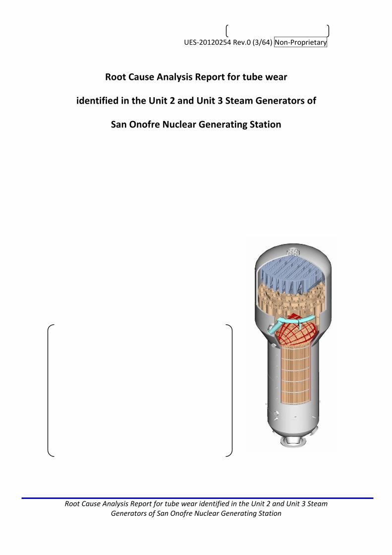
Root Cause Analysis Report for tube wear identified in the Unit 2 and Unit 3 Steam Generators of San Onofre Nuclear Generating Station
Root Cause Analysis Report for tube wear
identified in the Unit 2 and Unit 3 Steam Generators of
San Onofre Nuclear Generating Station

UES-20120254 Rev.0 (4/64) Non-Proprietary
Root Cause Analysis Report for tube wear identified in the Unit 2 and Unit 3 Steam Generators of San Onofre Nuclear Generating Station
Disclosure Statement
The following organization and programmatic Root Cause Analysis has been prepared
in accordance with the Mitsubishi Heavy Industries (MHI) corrective action program,
which uses an after-the-fact hindsight-based analysis. The information identified in this
evaluation was discovered and analyzed using all information and results available at
the time it was written. These results and much of the information considered in this
evaluation were not available to the organizations, management, or individuals during
the period that relevant actions were taken and decisions were made.
This evaluation does not attempt to make a determination whether any of the actions
or decisions taken by management, internal organizations, or individual personnel at
the time of the event was reasonable or prudent based on the information that was
known or available at the time they took such actions or made such decisions. Any
individual statements or conclusions included in the evaluation as to whether incorrect
actions may have been taken or improvements are warranted are based upon all of
the information considered, including information and results learned after-the-fact
and evaluation in hindsight after the results of actions or decisions are known, and do
not reflect any conclusion or determination as to the prudence or reasonableness of
actions or decisions at the time they were made.

UES-20120254 Rev.0 (5/64) Non-Proprietary
Root Cause Analysis Report for tube wear identified in the Unit 2 and Unit 3 Steam Generators of San Onofre Nuclear Generating Station
Table of contents
1.0 Executive Summary.................................................................................... 6
2.0 Background of the Incident........................................................................ 7
2.1Project Background.............................................................................. 7
2.2 Technical Specification requirements potentially involved in the
Problem................................................................................................ 9
3.0 Statement of Problem................................................................................ 10
4.0 Extent of Condition Evaluation................................................................... 10
5.0 Analysis, Results, and Conclusions.............................................................. 11
5.1 Evaluation Team Formation.................................................................. 11
5.2 Evaluation Methodology....................................................................... 11
5.3 Technical Investigation of the Incident................................................. 12
5.4 Description of Main Wear Mechanisms................................................ 14
5.5Discussion of Tube to Tube Wear.......................................................... 20
5.6 Discussion of Tube to AVB Wear........................................................... 23
5.7 Discussion of Retainer Bar to Tube Wear............................................. 23
5.8 Root Causes........................................................................................... 24
5.9 Contributing Causes............................................................................... 25
6.0 Corrective Action Matrix.............................................................................. 27
7.0 Extent of Cause Evaluation........................................................................... 32
8.0 Safety Culture Review.................................................................................. 33
Attachment-1 Cause-effect analysis............................................................ 41
Attachment-2 Barrier analysis..................................................................... 44
Attachment-3 Change analysis.................................................................... 47
Attachment-4 RCA charter.......................................................................... 54
Attachment-5 Time line.............................................................................. 55
Attachment-6 Interview list......................................................................... 60
Attachment-7 Reference documents.......................................................... 62

UES-20120254 Rev.0 (6/64) Non-Proprietary
Root Cause Analysis Report for tube wear identified in the Unit 2 and Unit 3 Steam Generators of San Onofre Nuclear Generating Station
1.0 Executive Summary
On January 31, 2012, after the replacement steam generators (RSGs) supplied by MHI
had been operating for approximately 11 months, SONGS Unit 3 was brought into an
unplanned shutdown due to primary to secondary leakage of approximately 82
gallons/day in one RSG. The direct cause of the leakage was determined to be tube to
tube wear in the free span section of the U-bend region of the RSG, leading to a leak
from one of the tubes in that region.
SONGS Unit 2 was in a refueling outage when the event occurred in Unit 3. During the
normally scheduled outage inspections of the Unit 2 RSGs, tube wear was discovered
in the vicinity of the retainer bars in the U-bend region of both RSGs. This wear was
determined to have been caused by random vibration of the retainer bars.
It was determined that all four RSGs experienced higher than expected tube wear. This
wear is comprised of: (i) tube to tube wear in the tube free-span sections between the
Anti-Vibration-Bars (AVBs) located in the U-bend region observed almost exclusively in
Unit 3; (ii) tube to AVB wear, observed at discrete tube to AVB intersections, with no
wear indications in the tube free-span sections (the tube to AVB wear indications are
short in length, and are associated with small tube motions); (iii) tube to Tube Support
Plate (TSP) wear; and (iv) retainer bar to tube wear. One RSG experienced minor tube
wear from a foreign object, which has since been removed.
MHI, working in conjunction with SCE personnel and other industry experts,
determined the mechanistic causes of the tube wear. MHI formed a team composed of
personnel from MHI and its U.S. subsidiary, plus outside consultants, to perform the
Root Cause Analysis (RCA) of the tube wear identified in the SONGS Unit 2 and Unit 3
RSGs. The two wear mechanisms that produced the deepest wear are evaluated in this
report. They include:
1. Tube to tube wear in the in-plane direction due to fluid-elastic instability (FEI)
2. Retainer bar to tube wear due to turbulence induced vibration (also referred to
as random vibration) and the low natural frequency of the retainer bar
Additionally, because many tubes exhibit it, this report also addresses a third wear
mechanism:
3. Tube-to-AVB wear caused by turbulence induced vibration (also referred to as
random vibration).
UES-20120254 Rev.0 (7/64) Non-Proprietary
Root Cause Analysis Report for tube wear identified in the Unit 2 and Unit 3 Steam Generators of San Onofre Nuclear Generating Station
The RCA team used Cause-effect analysis, Barrier analysis and Change analysis to arrive
at two Root Causes and three Contributing Causes. The Root Causes are:
1. Insufficient programmatic requirement to assure effective AVB contact force to
prevent in-plane fluid elastic instability and random vibration and subsequent
wear under high localized thermal-hydraulic conditions (steam quality (void
fraction), flow velocity and hydro-dynamic pressure).
2. The design control process did not provide sufficient direction to assure that an
evaluation of the need for an analysis of flow induced vibration of the retainer
bar was performed and verified.
The corrective actions to preclude repetition include:
1. Revise Procedure 5BBB60-N01 “Procedure for Controlling of the Design
Activities” to require that the need for effective tube to AVB contact force
under high localized thermal-hydraulic conditions (steam quality (void fraction),
flow velocity and hydro-dynamic pressure) be addressed in all MHI SG designs.
1.a Further revise Procedure 5BBB60-N01 “Procedure for Controlling of the
Design Activities” to require that sufficient contact force is assured under high
localized thermal-hydraulic conditions (steam quality (void fraction) flow
velocity and hydro-dynamic pressure), e.g., compare to the design parameters
of previous successful MHI steam generator designs.
2. Revise procedure 5BBB60-N01 “Procedure for Controlling of the Design
Activities” to require that retainer bars and other steam generator parts subject
to flow induced vibration be evaluated to determine the different analyses and
the level of analysis that need to be performed to support the steam generator
design.
2.0 Background of the Incident
2.1 Project Background
In September 2004, MHI was awarded a contract to replace Southern California
Edison’s (SCE) original steam generators (OSGs) at Units 2 and 3 of the San Onofre
Nuclear Generating Station (SONGS). The MHI-supplied replacement SGs (RSGs) had a
number of differences from the OSGs provided by Combustion Engineering. One of the
main differences was the substitution of Inconel 690 for Inconel 600 as the tube
material. Inconel 690 is more resistant to corrosion than Inconel 600. However, Inconel
UES-20120254 Rev.0 (8/64) Non-Proprietary
Root Cause Analysis Report for tube wear identified in the Unit 2 and Unit 3 Steam Generators of San Onofre Nuclear Generating Station
690 has a thermal conductivity approximately 10% less than that of Inconel 600. The
requirement that the SG’s thermal performance be maintained, in conjunction with
maintaining a specified tube plugging margin, necessitated increasing the tube bundle
heat transfer surface area from 105,000 ft2 to 116,100 ft2 (an 11% increase).The
Certified Design Specification SO23-617-01, Rev. 3 stated that SCE intended to use the
provisions of 10 C.F.R. §50.59 as the justification for the RSG design, which imposed
physical and other constraints on the characteristics of the RSG design in order to
assure compliance with that regulation. The RSGs were also required to fit within the
same space occupied by the OSGs.
The Certified Design Specification issued by SCE also required that MHI incorporate
many design changes to minimize degradation and maximize reliability. The following
are the design requirements specified for the U-bend supports:
“3.10.3.5 … The Supplier shall develop and submit for Edison’s approval an
Engineering and Fabrication Gap Control Methodology describing control of an
effective “zero” tube-to-flat bar gap, gap uniformity and parallelism of the
tube bundle in the out-of-plane direction prior to tube fabrication. The gap
statistical size (mean value +3sigma) shall not exceed 0.003”, and shall be
validated by empirical data.”
The Unit 2 RSGs were delivered to SONGS in February 2009 and installed during a
refueling outage between September 2009 and April 2010. The Unit 3 RSGs were
delivered to SONGS in October 2010 and installed during a refueling outage between
October 2010 and February 2011.
On January 31, 2012, after the Unit 3 RSGs had been operating for approximately 11
months, the unit was brought into an unplanned shutdown due to maximum primary
to secondary leakage of approximately 82 gallons/day in one RSG. The direct cause of
the leakage was determined to be tube to tube wear in the free span section of the
U-bend region of the RSG, leading to a leak from one of the tubes in that region.
Inspections of the Unit 2 RSGs(which was offline undergoing a refueling outage)
revealed significant tube wear in the vicinity of the retainer bars in the U-bend region.
In addition to these two forms of tube wear, all four RSGs were found to have
experienced higher than expected tube to Anti-Vibration-Bar (AVB) and tube to Tube
Support Plate (TSP) wear. One RSG had experienced minor tube wear due to a foreign
object.
UES-20120254 Rev.0 (9/64) Non-Proprietary
Root Cause Analysis Report for tube wear identified in the Unit 2 and Unit 3 Steam Generators of San Onofre Nuclear Generating Station
2.2 Technical Specification requirements potentially involved in the Problem
Technical Specification (TS) 3.4.17 requires that SG tube integrity be maintained and
that all SG tubes meeting the tube repair criteria be plugged in accordance with the
Steam Generator Program.
TS 5.5.2.11 requires a Steam Generator Program to be established and implemented to
ensure that SG tube integrity is maintained.
TS 5.5.2.11.b specifies three performance criteria that must be met for SG tube
integrity:
1. “Structural integrity performance criterion: All in-service steam generator tubes
shall retain structural integrity over the full range of normal operating conditions
(including startup, operation in the power range, hot standby, and cool down and all
anticipated transients included in the design specification) and Design Basis Accidents
(DBAs). This includes retaining a safety factor of 3.0 against burst under normal steady
state full power operation primary-to-secondary pressure differential and a safety
factor of 1.4 against burst applied to the design basis accident primary-to-secondary
pressure differentials. Apart from the above requirements, additional loading
conditions associated with the design basis accidents, or combination of accidents in
accordance with the design and licensing basis, shall also be evaluated to determine if
the associated loads contribute significantly to burst or rupture. In the assessment of
tube integrity, those loads that do significantly affect burst or rupture shall be
determined and assessed in combination with the loads due to pressure with a safety
factor of 1.2 on the combined primary loads and 1.0 on axial secondary loads.”
2. “Accident induced leakage performance criterion: The primary to secondary
accident induced leakage rate for any DBA, other than a SG tube rupture, shall not
exceed the leakage rate assumed in the accident analysis in terms of total leakage rate
for all SGs and leakage rate for an individual SG. Leakage is not to exceed 0.5 gpm per
SG and 1 gpm through both SGs.”
3. “The operational leakage performance criterion is specified in LCO 3.4.13, “RCS
Operational Leakage.” [This LCO is applicable in Modes 1-4 and states RCS operational
leakage shall be limited to: (a) no pressure boundary leakage; (b) 1 gpm unidentified
leakage; (c) 10 gpm identified leakage; and (d) 150 gallons per day (gpd) primary to
secondary leakage through any one SG.”]

UES-20120254 Rev.0 (10/64) Non-Proprietary
Root Cause Analysis Report for tube wear identified in the Unit 2 and Unit 3 Steam Generators of San Onofre Nuclear Generating Station
3.0 Statement of Problem
This Root Cause Analysis (RCA) was performed based on the following problem
statement, which was adopted as part of the Root Cause Analysis Team Charter:
(1) Requirement No Primary-to-Secondary Leakage due to Defects in any of the RSG Units for the duration of the Warranty Period. (per 17.2.3 of General T&C with EMS)
(2) Deviation
Unit 3 SG-B (SCE SG088) experienced tube leakage during operation and failure of eight tubes during in-situ pressure testing. (Both due to Defects)
(3) Consequences (For MHI)
・ 10CFR21 Report required
4.0 Extent of Condition Evaluation
To determine the extent of condition, other MHI SGs with similar design and
construction were analyzed to see if the same tube wear conditions identified at the
SONGS RSGs were present.
The replacement steam generators for OPPD’s Fort Calhoun Nuclear Generating
Station are the only other steam generators designed by MHI operating in the United
States. The OPPD RSGs replaced Combustion Engineering OSGs and are of a similar
design and construction as the SONGS RSGs with certain differences, including:
Identical tube diameter (3/4”) and wall thickness (0.043”)
Identical tube pitch (1.0” equilateral triangle)
Identical pitch-to-diameter ratio (P/D = 1.33)
OPPD has greater average tube to AVB gap
OPPD RSGs are smaller than SONGS RSGs
Fewer AVBs than SONGS
Fewer tubes than SONGS
Smaller U-bend radius than SONGS
Lower maximum steam quality (void fraction) than SONGS

UES-20120254 Rev.0 (11/64) Non-Proprietary
Root Cause Analysis Report for tube wear identified in the Unit 2 and Unit 3 Steam Generators of San Onofre Nuclear Generating Station
The Fort Calhoun RSGs have operated more than three fuel cycles with no evidence of
U-bend tube degradation (no tube-to-AVB wear, no tube-to-tube wear, and no
retainer bar-to-tube wear).Other steam generators designed by MHI (operating
outside of the United States)are of a different design and have a variety of tube sizes,
tube pitches and operating conditions. These steam generators have years of
operation without significant tube wear. Therefore, it is concluded that the MHI SGs in
operation today are not part of extent of condition. However, these other MHI SGs will
be evaluated for susceptibility based on extent of cause.
5.0 Analysis, Results, and Conclusions
5.1 Evaluation Team Formation
On March 23, 2012 MHI formed a team composed of personnel from MHI and its U.S.
subsidiary, plus outside consultants, to perform the Root Cause Analysis of the tube
wear identified in the SONGS Unit 2 and Unit 3 RSGs. The team was given the task of
investigating the organizational and programmatic Root Causes of the tube wear. SCE
also performed separate technical and Root Cause evaluations.
The Root Cause Analysis commenced on March 26, 2012, and was conducted
concurrently with the development of MHI’s technical evaluation reports.
5.2 Evaluation Methodology
The evaluation team used the results of the technical investigations (identified below)
as the basis for its analysis of the organizational and programmatic Root Causes for the
tube to tube wear, retainer bar to tube wear, and tube to AVB wear seen in the RSGs.
The extent of cause was evaluated based on organizational and programmatic causes.
The team closely consulted with the MHI engineering team performing the technical
evaluations, and with SCE representatives, in order to understand fully the technical
causes of the tube wear. Additionally, the evaluation team gathered evidence through
interviews, examination of procedures and plans and previous audits and surveillances,
review of design and technical review meeting documents, and analysis of technical
work products.
To determine the organizational and programmatic Root and Contributing Causes of
the three wear mechanisms evaluated in this report, the evaluation team used three

UES-20120254 Rev.0 (12/64) Non-Proprietary
Root Cause Analysis Report for tube wear identified in the Unit 2 and Unit 3 Steam Generators of San Onofre Nuclear Generating Station
cause analysis tools: Cause-effect analysis, Barrier analysis, and Change analysis. The
Root and Contributing Causes were determined primarily through the Cause-effect
analysis. The results of the Barrier analysis and the Change analysis support the
findings of the Cause-effect analysis. In addition to supporting the Cause-effect
analysis, the Change analysis identified an additional Contributing Cause.
In performing these analyses, the evaluation team closely looked at and took into
account the technical evaluations prepared by MHI and SCE to understand fully the
mechanistic causes of the tube to tube wear, the retainer bar to tube wear, and the
tube to AVB wear, in order to better assess the underlying organizational and
programmatic Root and Contributing Causes. The team then reviewed and evaluated,
with the benefit of what is now known in hindsight, the design process for the RSGs to
identify what could have been done differently that would have prevented the tube
wear from occurring. Based on its reviews, the evaluation team identified the
programmatic Root Causes of the RSG tube wear.
5.3 Technical Investigation of the Incident
MHI performed technical evaluations to identify the mechanistic causes of the tube
wear, which identified fluid elastic instability as the mechanistic cause of the tube to
tube wear, turbulence induced vibration (often referred to as “random vibration”
because the excitation modes over time are unpredictable) as the mechanistic cause of
the tube to AVB wear, and turbulence induced vibration of the retainer bar as the
mechanistic cause of the retainer bar to tube wear. These evaluations are reflected in
the MHI reports Tube Wear of Unit-3 RSG Technical Evaluation Report, L5-04GA564
Rev.9; Retainer Bar Tube Wear Report, L5-04GA561 Rev.4; Validity of Use of the FIT-III
Results During Design, L5-04GA591 Rev. 3;and Supplemental Technical Evaluation
Report, L5-04GA588 draft. SCE also performed Root Cause evaluations.SCE reports
Root Cause Evaluation NN201843216 Steam Generator Tube Wear San Onofre Nuclear
Generating Station, Unit 2dated April 2, 2012, and Root Cause Evaluation: Unit 3
Generator Tube Leak and Tube-to-Tube Wear Condition Report: 201836127,
Rev.0contain the SCE Root Cause evaluations.
The MHI and SCE mechanistic cause analysis reports used Fault Tree Analysis and
Kepnor-Tregeo (respectively) as the primary analysis tools. Each of these analyses
considered a broad range of potential causes. The following causes were evaluated in
detail:

UES-20120254 Rev.0 (13/64) Non-Proprietary
Root Cause Analysis Report for tube wear identified in the Unit 2 and Unit 3 Steam Generators of San Onofre Nuclear Generating Station
Manufacturing/fabrication Shipping
Primary side flow induced vibration Divider plate weld failure and repair
Additional rotations following divider
plate repair
TSP distortion
Tube bundle distortion during operation
(flowering)
T/H conditions/modeling
Each of these causes is evaluated in the MHI and SCE technical evaluation reports.
These technical evaluations identified five different wear categories for the tubewear
observed in the SONGS RSGs. Two of these wear categories are responsible for the
most significant instances of tube degradation(in terms of the depth of wear and
potential for failing to meet the technical specification requirements) and are being
evaluated in this report to determine their organizational and programmatic causes.
The two significant wear categories that are evaluated in this RCA are:
1. Tube to Tube Wear due to in-plane FEI: Tube to tube wear was found in the
U-bend region, located between AVBs, in the free span. Many of the tubes
exhibiting tube to tube wear also exhibited wear at the AVBs and TSPs, in
particular at the top tube support plate. For tubes with wear at the top tube
support plate, it is considered that the entire tube, including its straight region,
is vibrating. Tube to tube wear occurs when there is tube in-plane motion
(vibration) with a displacement (amplitude) greater than the distance between
the tubes in the adjacent rows, resulting in tube-to-tube contact.1
2. Retainer Bar to Tube Wear due to Flow Induced Vibration: Tube wear occurred
on tubes at the periphery of the U-bend, adjacent to the retainer bars. These
tubes have no wear indications at any other location along their length, which
1 Some of the tubes with tube-tube wear did not experience large amplitude vibration
but were impacted by tubes that did experience large amplitude vibration. Also the
two tubes in Unit 2 with tube-to-tube wear had different wear characteristics than the
Unit 3 tube-to-tube wear.

UES-20120254 Rev.0 (14/64) Non-Proprietary
Root Cause Analysis Report for tube wear identified in the Unit 2 and Unit 3 Steam Generators of San Onofre Nuclear Generating Station
indicates that they are stationary, and that the wear is caused by the
movement (vibration) of the retainer bars.
Additionally, because many tubes have smaller-depth wear indications at the AVB
intersections, this report also addresses another wear category:
3. Tube to AVB Wear (for tubes without free span wear) due to random vibration:
Tube wear occurred at discrete tube-to-AVB intersections, with no wear
indications in the tube free-span sections. These wear indications are short in
length and are associated with small tube motions.
The other two categories of wear identified were: (i) wear at the TSPs (small bend
radius tubes and tubes at the tube bundle periphery), and (ii) wear due to a foreign
object. These two categories are not considered in this report because the degree of
wear due to them is relatively small.
The conclusions of the MHI and SCE technical evaluations have been accepted as the
basis of this analysis. To the extent these evaluations are revised or amended to reflect
additional information or new understandings, this evaluation may be affected.
5.4 Description of Main Wear Mechanisms
Fluid Elastic Instability
In a tube array, a momentary displacement of one tube from its equilibrium position
will alter the flow field and change the forces to which the neighboring tubes are
subjected, causing them to change their positions in a vibratory manner. When the
energy extracted from the flow by the tubes exceeds the energy dissipated by damping
it produces fluid elastic vibration.
Fluid Elastic Instability (FEI) is a term used to describe a range of tube vibrations that
starts at a point on a curve of vibration amplitude versus flow velocity. As depicted in
Figure 1, one axis (Y) of that curve is vibration amplitude and the other (X) is flow
velocity. The graph shows that as flow velocity increases vibration amplitude increases
at a small linear rate until it reaches a point where the slope of the curve increases
abruptly. The point in the curve where the slope changes is termed “critical velocity”.
The critical velocity is a function of several variables. These include tube natural
frequency, which is dependent on the tube geometry and support conditions, damping,

UES-20120254 Rev.0 (15/64) Non-Proprietary
Root Cause Analysis Report for tube wear identified in the Unit 2 and Unit 3 Steam Generators of San Onofre Nuclear Generating Station
which is a function of the steam-to-water ratio, flow velocity, which is dependent of
the tube spacing.
Figure 1
As discussed below and in the technical reports referenced above (See Supplemental
Technical Evaluation Report), MHI has determined that, due to ineffective support for
the tubes in the in-plane direction resulting from the very small and uniform tube-to
AVB gaps, some of the tubes exceeded the fluid elastic critical velocity resulting in
in-plane FEI, which in turn produced the large amplitude tube-to-tube wear. This
mechanism is influenced by the local thermal hydraulic conditions around the tube.
Regions of high void fraction have lower tube damping, which reduces the fluid elastic
critical velocity threshold. High void fraction regions also have higher cross flow
velocities. Therefore, tubes with low or no contact force in the region of highest void
fraction are most susceptible to this mechanism.
Random Vibration
Random vibration is the vibration mechanism caused by flow turbulence that changes
proportionately to changes in the fluid flow forces(dynamic pressure) and is present at
all flow velocities. Turbulent flow forces are random in nature, so this form of vibration
is referred to as random vibration. As discussed below and in the technical reports
referenced above, MHI has determined that the tube wear at the AVB intersections
UES-20120254 Rev.0 (16/64) Non-Proprietary
Root Cause Analysis Report for tube wear identified in the Unit 2 and Unit 3 Steam Generators of San Onofre Nuclear Generating Station
with no wear indications in the tube free span sections is due to turbulence induced
vibration caused by insufficient contact force between the tube and the AVBs due to
very small, uniform tube-to-AVB gaps. Since dynamic pressure and damping is
proportional to the void fraction, tubes in the region of highest void fraction are most
susceptible to this mechanism.
Tube to Tube Wear
Tube-to-tube wear was caused by large displacements of tubes in the in-plane
direction. Tubes are known to have moved in-plane because of the locations and
magnitudes of their wear scars. The wear scars indicate that the tubes were generally
vibrating in their first fundamental in-plane mode, which implies that none of the
twelve (12) AVB supports were restraining the tube motion. Yet, it also indicates that
the tube-to-AVB gaps are very small and uniform, because none of the tubes exhibited
out-of-plane FEI, which is the tube’s preferential fluid elastic vibration mode.2 It can
therefore be concluded that the tube-to-AVB contact forces were negligible and the
tube-to-AVB gaps (on both sides of each tube at each of the 12 AVB intersections)
were very small. Both of these conclusions are consistent with the original design
intent discussed below.
In-plane FEI is a phenomenon that had not been experienced in nuclear U-tube steam
generators prior to its being identified in the SONGS RSGs. The practice in the nuclear
industry at the time the SONGS RSGs were designed was to provide measures to
preclude out-of-plane FEI in the U-bend region, which was based on the understanding
set forth above. Reflecting this industry practice, the Japan Society of Mechanical
Engineers’ “Guideline for Fluid-elastic Vibration Evaluation of U-bend Tubes in Steam
Generators” states that in-plane FEI does not need to be considered if out-of-plane FEI
is controlled. The design of the SONGS RSGs is consistent with the contemporary
industry practice and guidance. The RSGs were designed to provide effective tube
support (by means of AVBs) to avoid out-of-plane FEI. MHI sought to maximize the
2In U-bend SGs, because the tubes are curved, for the same support conditions the
critical velocity for out-of-plane FEI will be lower than that for in-plane FEI because the
natural frequency of tubes in the in-plane direction is higher, due to the tubes greater
stiffness in-plane, than the natural frequency of the tubes in the out-of-plane
direction.
UES-20120254 Rev.0 (17/64) Non-Proprietary
Root Cause Analysis Report for tube wear identified in the Unit 2 and Unit 3 Steam Generators of San Onofre Nuclear Generating Station
adequacy of the supports against out-of-plane FEI by increasing the number of AVBs to
a number, 12, that exceeds that in other U-tube SGs designed by MHI or by other
major U-tube SG manufacturers.
Minimizing tube vibration wear in the U-bend region was given high priority in the
SONGS RSG Design Specification, the RSG design program, and in the manufacturing
processes. Early in the project, SCE and MHI formed an AVB Design Team with the goal
of minimizing U-bend tube vibration and wear. The AVB Design Team conducted
numerous technical and design review meetings. The agreed-upon tube bundle
U-bend support design and fabrication were as follows:
Six (6) V-shaped AVBs (three sets of two) were to be provided between each
tube column (12 AVB intersections total around the U-bend).
Tube and AVB dimensional control, including increasing the AVB thickness was
to achieve an effective “zero” tube-to-AVB gap under operating (hot)
conditions with gap uniformity and parallelism being maintained throughout
the tube bundle. Effective “zero” gap was desirable as an industry practice in
order to maximize the effectiveness of the supports. The tube and AVB
tolerances were to be tighter than that of any prior MHI SG.
Excessive preload contact force was to be avoided in order to minimize
ding/dent indications, and to maintain mechanical damping and thus minimize
tube vibration.
MHI investigated field experience with U-bend tube degradation using INPO, NRC and
NPE data bases, and concluded that the SONGS RSGs were designed to minimize the
potential for tube wear by providing extra support points with shorter spans in the
U-bend region along with effective zero tube-to-AVB gaps.
In the fabrication process, MHI manufacturing focused on achieving very small,
uniform tube-to-AVB gaps during assembly.
The AVB Design Team included consultants with knowledge and experience in the
design and construction large U-bend SGs. One consultant had experience with the
design of a plant whose SGs were similar to the proposed RSGs (the “comparison” or
“reference” plant). Together, the AVB Design Team concluded that the SONGS RSGs
had more tube vibration margin than the comparison plant, which had experienced
only a small number of tube wear occurrences. This conclusion was due to the
following considerations:(i) SONGS RSG tubes are larger, have thicker walls, and are
UES-20120254 Rev.0 (18/64) Non-Proprietary
Root Cause Analysis Report for tube wear identified in the Unit 2 and Unit 3 Steam Generators of San Onofre Nuclear Generating Station
stiffer than those of the comparison plant; (ii) the SONGS distances between AVB tube
supports are shorter than those at the comparison plant; (iii) SONGS has 12 AVB tube
supports where the comparison plant only has 10; (iv) SONGS’s tube-to-AVB gap
requirement was more stringent than that of the comparison plant.
The Certified Design Specification SO23-617-01, Rev. 3, issued by SCE required an
effective zero gap and gap uniformity and parallelism of the tube bundle in the
out-of-plane direction. Establishing the goal to reduce tube-AVB gaps to an effective
zero gap was in accordance with well accepted industry practice and understanding
that minimizing gaps was highly desirable in preventing tube vibration wear. MHI had
sought to minimize tube-AVB gaps in its previous SG designs. However, MHI took
additional steps to minimize the tube-AVB gaps for the SONGs RSGs and to provide for
gap uniformity throughout the U-bend region of the tube bundle.
These steps included increasing the nominal thickness of the AVB compared to
previous MHI SGs and reducing the manufacturing tolerance of AVB thickness and
twist in order to achieve effective zero gaps and provide gap uniformity. Steps were
taken as well to minimize tube ovality and to minimize variations from the design value.
Also, numerous additional steps were taken in fabricating the tube bundle to assure
gap uniformity throughout the U-bend region. Additionally, in the fabrication of the
Unit 2 RSGs MHI identified other enhancements that were implemented in the
fabrication of the Unit 3 RSGs. These included, for example, taking steps to minimize
AVB twist by applying a larger(from tons to tons) pressing force in the Unit
3 fabrication and thus providing for more uniform AVBs in the Unit 3 RSGs.
The adequacy of the design against out-of-plane FEI was confirmed through test data
and analyses that conservatively assumed that one of the AVBs provided in the design
was inactive (that is, ineffective against out-of-plane FEI).Analyses using this criterion
showed that an adequate margin against out-of-plane FEI exists in the SONGS RSGs. An
additional AVB had been added to the design to provide further margin against
out-of-plane FEI.
The MHI technical evaluations performed after the January 2012 incident determined
that, despite the robustness of the MHI design, in-plane FEI had occurred. This
occurrence was due to a combination of a lack of effective contact forces between the
tube and AVB in the in-plane direction and localized thermal-hydraulic (T/H) conditions
(high steam quality (void fraction) and high fluid velocity).The evaluations found that
the average contact force in the Unit 3 RSGs was smaller than the average contact
force in the Unit 2 RSGs. Therefore, the contact forces of the Unit 3 RSGs were more

UES-20120254 Rev.0 (19/64) Non-Proprietary
Root Cause Analysis Report for tube wear identified in the Unit 2 and Unit 3 Steam Generators of San Onofre Nuclear Generating Station
likely to be ineffective in preventing in-plane motion of tubes so that the Unit 3 RSGs
were more susceptible to in-plane tube vibration than those in Unit 2. The difference
in the contact forces between the Unit 2 and Unit3 RSGs is caused by the reduction in
dimensional variations during the manufacture of the Unit 3 RSGs, mainly due to
improvement of the control over tube and AVB dimensions in the manufacture of the
Unit 3 RSGs. The reduced contact forces resulted in far more tubes in the Unit 3 RSGs
experiencing tube-to-tube wear than those in the Unit 2 RSGs. For those tubes, given
these support conditions, the vibratory energy in high localized thermal-hydraulic (T/H)
environment produced in-plane FEI that led to large amplitude displacement of the
tubes in the in-plane direction, which caused wear from contact between adjacent
tubes.
Tube Wear at AVBs
Tube-to-AVB wear is a function of the amplitude of the random tube vibration and the
tube-to-AVB gap. Where there is a gap between the AVB and the tube and the
vibration amplitude is less than the gap, there will be minimal or no wear. If the AVB is
in contact with the tube but there is insufficient contact force to lock the two together,
there will be relative motion between the two and wear will occur. In the case where
there is sufficient contact force to lock the two together, there will be minimal or no
relative motion and only minimal wear will occur. In the SONGS RSGs, the zero gap
design philosophy resulted in the AVBs being in contact with the tubes or very close to
the tubes, but there was insufficient contact force to lock the two together, thus
allowing tube wear at the AVBs.
The degree of wear is also affected by the amount of damping provided by the water
film between the tubes and AVBs. In the SONGS RSGs, damping was reduced in areas
of high steam quality (void fraction)because there is less two-phase damping and little
or no water film in the gaps between the tubes, resulting in more pronounced wear.
Tube Wear at Retainer Bars
The tubes exhibiting retainer bar wear have no indications of tube-to-tube or
tube-to-AVB wear, which indicates that the wear is caused solely by retainer bar
vibration. The SONGS RSGs have two types of retainer bars:
diameter and diameter. Tube wear was only found on tubes adjacent
to the smaller diameter retainer bars. The retainer bars with the smaller diameter have
a relatively long span as compared with those for other SGs fabricated by MHI, which
means that the natural frequency of these retainer bars is lower, making them more

UES-20120254 Rev.0 (20/64) Non-Proprietary
Root Cause Analysis Report for tube wear identified in the Unit 2 and Unit 3 Steam Generators of San Onofre Nuclear Generating Station
likely to vibrate. This type of wear is caused by random flow-induced vibration of the
retainer bars caused by the secondary fluid exiting the tube bundle.
5.5 Discussion of Tube to Tube Wear
Tube Contact Force
During the fabrication of the AVBs and the tubing and assembly of the tube bundle,
MHI’s manufacturing practices achieved dimensional control that resulted in smaller
tube-to-AVB gaps and smaller tube-to-AVB contact forces. It was not recognized at the
time that a certain amount of tube-to-AVB contact force was required to prevent
in-plane FEI under high steam quality (void fraction) conditions, because the contact
force serves to increase the in-plane natural frequency of the tube.
The technical investigations after the tube leak incident determined that the amount
of contact force necessary to prevent in-plane FEI depends on the localized
thermal-hydraulic conditions (steam quality (void fraction), flow velocity and
hydro-dynamic pressure).As the steam quality (void fraction) increases, the amount of
contact force necessary to prevent vibration increases. This increase in required
contact force occurs because as the steam quality (void fraction) becomes higher, the
damping provided by the liquid phase in the form of a liquid film decreases.
The reduced in-plane contact force due to the SONGS “effective zero gap” design and
the avoidance of “excessive preload” resulted in lowering the tubes’ natural frequency
in the in-plane direction. The combination of the localized high steam quality (void
fraction) and reduced tube to AVB contact force resulted in exceeding the in-plane
critical velocity, which created a condition that led to tube to tube contact.
The dominant role played by the low contact force is reflected by the differences in the
tube-to-tube wear that was observed in the Unit 2 and the Unit 3 RSGs. Each of the
Unit 3 RSGs had approximately 160 tubes that experienced tube-to-tube wear whereas
only one of the Unit 2 RSGs experienced tube-to-tube wear in just two tubes, even
though the Unit 2 RSGs have operated twice as long as the Unit 3 RSGs. MHI did a
comprehensive statistical evaluation of the contact forces between the tubes and the
AVBs of the two units and concluded, based on the manufacturing data , that the
contact force between the tubes and the AVBs in the Unit 2 RSGs is approximately
double the contact force in the Unit 3 RSGs. Thus, the lower contact forces in Unit 3
are consistent with the conditions determined necessary to permit in-plane FEI to
occur and with the fact that tube-to-tube wear occurred almost exclusively in Unit 3.
UES-20120254 Rev.0 (21/64) Non-Proprietary
Root Cause Analysis Report for tube wear identified in the Unit 2 and Unit 3 Steam Generators of San Onofre Nuclear Generating Station
Thermal-hydraulic Conditions
Many analyses are performed during the steam generator design process. One of
these is MHI’s FIT-III tube bundle flow analysis, which calculates tube bundle thermal /
hydraulic parameters, including U-bend flow velocity and steam quality (void
fraction).An after-the-fact comparison between the T/H parameters that FIT-III
predicted and those predicted by ATHOS, another T/H code, determined that FIT-III’s
calculated values are lower than those obtained using ATHOS. Part of the difference
was because the pressure loss coefficients for the tube bundle and the two-phase
mixture density utilized in the two codes were different.
Also, during the computation of the flow velocity, MHI used an inappropriate
definition of the gap between tubes, with the result that the flow velocities were
underestimated.
These differences between MHI’s use of the FIT-III model and the ATHOS model
resulted in a higher margin to out-of-plane FEI than the margin that would have been
determined using the appropriate the definition of the gap and an ATHOS-calculated
steam quality (void fraction). The margin calculated using ATHOS, nonetheless, would
still have resulted in adequate margin against out-of-plane FEI. Using the ATHOS
outputs, with all AVBs assumed active, the stability ratio was less than 1.0 for
out-of-plane FEI, even for those case studies assuming reduced damping that could
occur under high void fraction conditions.3 Thus, the use of ATHOS as opposed to
FIT-III would not have identified an inadequate design margin against FEI.
Moreover, because industry practice was focused on out-of-plane FEI, use of ATHOS
would not have identified the potential for in-plane vibration. Both the academic
literature and subsequently conducted tests show that the thermal-hydraulic
environment under which in-plane FEI arises is different from those that result in
out-of-plane FEI. (See Supplemental Technical Evaluation Report). If the steam quality
(void fraction) predicted by FIT-III had been the same as the ATHOS calculated value,
3The maximum stability ratio based on ATHOS outputs for all supports are active
is , which is less than 0.75, which is the conservative industry practice for judging
acceptability of stability ratios (which in turn is less than the ASME Section III Appendix
N-1330 recommended stability ratio criterion of 1.0). Assuming reduced damping, the
maximum stability ratio calculated using ATHOS is .

UES-20120254 Rev.0 (22/64) Non-Proprietary
Root Cause Analysis Report for tube wear identified in the Unit 2 and Unit 3 Steam Generators of San Onofre Nuclear Generating Station
and if the appropriate tube to tube gap value had been utilized to compute the flow
velocity, MHI would have identified a decreased margin against out-of-plane FEI. In
that case, MHI might have incorporated an additional AVB to increase the design
margin against out-of-plane FEI, but would not have taken measures to protect against
in-plane FEI, for it was assumed (as was the practice and guidance in the industry) that
the controlling effect of a well-designed AVB system was adequate to preclude it.
Thus, not using ATHOS, which predicts higher void fractions than FIT-III at the time of
design represented, at most, a missed opportunity to take further design steps, not
directed at in-plane FEI, that might have resulted in a different design that might have
avoided in-plane FEI. However, the AVB Design Team recognized that the design for
the SONGS RSGs resulted in higher steam quality (void fraction) than previous designs
and had considered making changes to the design to reduce the void fraction (e.g.,
using a larger downcomer, using larger flow slot design for the tube support plates,
and even removing a TSP). But each of the considered changes had unacceptable
consequences and the AVB Design Team agreed not to implement them. Among the
difficulties associated with the potential changes was the possibility that making them
could impede the ability to justify the RSG design under the provisions of 10 C.F.R.
§50.59. Thus, one cannot say that use of a different code than FIT-III would have
prevented the occurrence of the in-plane FEI observed in the SONGs RSGs or that any
feasible design changes arising from the use of a different code would have reduced
the void fraction sufficiently to avoid tube-to-tube wear.
For the same reason, an analysis of the cumulative effects of the design changes
including the departures from the OSG’s design and MHI’s previously successful
designs would not have resulted in a design change that directly addressed in-plane
FEI.
Summary
Thus, the organizational and programmatic Root Cause for the in-plane FEI as set forth
in this RCA is the insufficient programmatic requirement to assure effective AVB
contact force to control in-plane FEI under high localized thermal-hydraulic conditions
(steam quality (void fraction), flow velocity and hydrodynamic pressure). The
underlying reason for this insufficiency is that the MHI SONGS RSG design did not
consider the phenomenon of in-plane FEI because contemporary knowledge and
industry U-tubeSG operation experience did not indicate a need to consider in-plane
FEI.
UES-20120254 Rev.0 (23/64) Non-Proprietary
Root Cause Analysis Report for tube wear identified in the Unit 2 and Unit 3 Steam Generators of San Onofre Nuclear Generating Station
5.6 Discussion of Tube to AVB Wear
Tube-to-AVB wear in the SONGS RSG occurs at the tube-to-AVB intersections and is
produced by turbulence induced (random) vibration. This population only includes
tubes with wear at the tube-to-AVB intersections with no wear indications in the tube
free-span sections.
Tube wear at the AVB intersections (in the absence of tube-to-tube free span wear)
occurs when the tube movement causes it to impact or slide along the supporting
AVBs. The most common cause of this condition is out-of-plane FEI. In the SONGS RSG
design, the large number of AVB supports and the superior gap control prevent
out-of-plane FEI. However, because of the low contact forces between tubes and AVBs,
the very small and uniform tube-to-AVB gaps, and the localized T/H conditions (high
steam quality (void fraction) and high flow velocity), turbulent flow conditions are
sufficient to produce tube wear at the AVB intersections. Again the effect of the
different contact forces between Unit 3 and Unit 2 can be seen in the observed
tube-to-AVB wear populations of the two units. Unit 2 had about two-thirds as many
tube-to-AVB indications than Unit-3 and Unit 2 operated longer than Unit 3, indicated
that the wear rate is greater at Unit 3. This is attributable to the lower contact forces.
(See Supplemental Technical Evaluation Report).
As was the case with tube-to-tube wear, it was not recognized at the time of the RSG
design that a certain amount tube to AVB contact force is required to prevent random
vibration under high localized thermal-hydraulic conditions (steam quality (void
fraction), flow velocity and hydro-dynamic pressure).The combination of the reduced
tube to AVB contact force and the localized T/H conditions (high steam quality (void
fraction) and high flow velocity) resulted in tube to AVB wear.
5.7 Discussion of Retainer Bar to Tube Wear
The design function of the retainer bar is to support the AVB assembly during
manufacturing and prevent excessive AVB assembly movement during operational
transients. The retainer bar must be strong enough to support the AVB assembly and
fit within the physical constraints of the U-bend.
The tubesheet drilling pattern is one of the first design decisions made for a new steam
generator and it is at that time that each tube location along the periphery of the tube
bundle is established. The tube bundle design thus determines the retainer bar’s
length and thickness. At SONGS, in order to accommodate the increased number of

UES-20120254 Rev.0 (24/64) Non-Proprietary
Root Cause Analysis Report for tube wear identified in the Unit 2 and Unit 3 Steam Generators of San Onofre Nuclear Generating Station
tubes, the retainer bars are relatively long and thin as compared to the retainer bars in
other SGs designed by MHI, resulting in their having low natural frequencies.
The engineer responsible for the retainer bar design did not recognize the need to
analyze the retainer bar for flow induced vibration because no such analysis had been
performed on previous MHI SG designs. The design control procedure for this design
activity did not identify this issue, nor was it recognized during the design review
process.
During operation, the secondary flow velocity and steam quality (void fraction) created
turbulent flow conditions capable of causing high amplitude vibration if the retainer
bar natural frequency was low enough, which turned out to be the case. The high
amplitude vibration resulted in the retainer bar contacting some tubes and causing
tube wear.
5.8 Root Causes
As used in this evaluation, “Root Causes” are defined as the basic reasons (e.g.,
hardware, process, or human performance) for a problem, which if corrected, will
prevent recurrence of that problem.
The programmatic Root Causes of the RSG tube wear are:
1. Insufficient programmatic requirement to assure effective AVB contact force to
prevent in-plane fluid elastic instability and random vibration and subsequent
wear under high localized thermal-hydraulic conditions (steam quality (void
fraction), flow velocity and hydro-dynamic pressure).
Basis: The evaluation team concluded that the fundamental Root Cause for the
in-plane FEI and the resulting tube-to-tube wear was the fact that in-plane FEI
was not considered in the design of the SONGS RSGs. The fundamental reason
for this lack of consideration was that industry practice and guidance,
supported by the operating experience up to that time of U-bend type steam
generators, indicated that the control out-of-plane FEI would prevent the
occurrence of in-plane FEI.
Likewise, the evaluation team concluded that the tube to AVB wear was caused
by insufficient contact force under high localized thermal-hydraulic conditions,
which was not recognized at the time of the design of the SONGS RSGs, and
that the fundamental reasons for the ineffectiveness of the contact force were
the established industry practice of minimizing the tube support gaps and
UES-20120254 Rev.0 (25/64) Non-Proprietary
Root Cause Analysis Report for tube wear identified in the Unit 2 and Unit 3 Steam Generators of San Onofre Nuclear Generating Station
avoiding an excessive preload as well as other steps to control gap uniformity
and parallelism.
2. The design control process did not provide sufficient direction to assure that an
evaluation of the need for an analysis of flow induced vibration of the retainer
bar was performed and verified.
Basis: The evaluation team concluded that the fundamental reason for the
retainer bar FIV was the lack of clear direction in the MHI design procedures to
require an evaluation to determine the different analyses and the level of
analysis that were required for the RSG design in light of changes in the SONGS
RSG design from previous MHI steam generator designs.
5.9 Contributing Causes
As used in this evaluation, “Contributing Causes” are defined as causes that by
themselves would not create the problem but are important enough to be recognized
as needing corrective action. Contributing causes are sometimes referred to as causal
factors. Causal factors are those actions, conditions, or events that directly or indirectly
influence the outcome of a situation or problem. The evaluation team closely
evaluated the mechanistic causes and the design process for the potential existence of
Contributing Causes.
The programmatic Contributing Causes of the RSG tube wear are:

UES-20120254 Rev.0 (26/64) Non-Proprietary
Root Cause Analysis Report for tube wear identified in the Unit 2 and Unit 3 Steam Generators of San Onofre Nuclear Generating Station

UES-20120254 Rev.0 (27/64) Non-Proprietary
Root Cause Analysis Report for tube wear identified in the Unit 2 and Unit 3 Steam Generators of San Onofre Nuclear Generating Station
6.0 Corrective Action Matrix
Cause Corrective Action Due Date
Root Cause
1:Insufficient
programmatic
requirement to assure
effective AVB contact
force to prevent
in-plane fluid elastic
instability and random
vibration and
subsequent wear
under high localized
thermal-hydraulic
conditions (steam
quality (void fraction),
flow velocity and
hydro-dynamic
pressure).
CAPR 1:Revise Procedure
5BBB60-N01 “Procedure for
Controlling of the Design Activities”
to require that the need for effective
tube to AVB contact force under high
localized thermal-hydraulic
conditions(steam quality (void
fraction), flow velocity and
hydro-dynamic pressure) be
addressed in all MHI SG designs.
Completed
CAPR 1.a:Further revise Procedure
5BBB60-N01 “Procedure for
Controlling of the Design Activities”
to require that sufficient contact
force is assured under high localized
thermal-hydraulic conditions (steam
quality (void fraction) flow velocity
and hydro-dynamic pressure), e.g.,
compare to the design parameters of
previous successful MHI steam
generator designs.
11/15/2012
CA 1:Provide training for all Steam
Generator Engineers (included new
hires and continuing training)
covering this event and the details
concerning in-plane FEI and tube-AVB
wear under high localized
thermal-hydraulic conditions (steam
quality (void fraction), flow velocity
and hydro-dynamic pressure).
Completed

UES-20120254 Rev.0 (28/64) Non-Proprietary
Root Cause Analysis Report for tube wear identified in the Unit 2 and Unit 3 Steam Generators of San Onofre Nuclear Generating Station
Cause Corrective Action Due Date
Root Cause 2:The
design control process
did not provide
sufficient direction to
assure that an
evaluation of the need
for an analysis of flow
induced vibration of
the retainer bar was
performed and
verified.
CAPR 2:Revise procedure
5BBB60-N01 “Procedure for
Controlling of the Design Activities”
to require that retainer bars and
other steam generator parts subject
to flow induced vibration be
evaluated to determine the different
analyses and the level of analysis that
need to be performed to support the
steam generator design.
10/31/2012
CA 2:Revise Engineer Training
program (included new hires and
continuing training) to include the
necessary assessment for required
analyses of each Steam Generator
part subject to flow induced
vibration.
10/31/2012

UES-20120254 Rev.0 (29/64) Non-Proprietary
Root Cause Analysis Report for tube wear identified in the Unit 2 and Unit 3 Steam Generators of San Onofre Nuclear Generating Station
Cause Corrective Action Due Date

UES-20120254 Rev.0 (30/64) Non-Proprietary
Root Cause Analysis Report for tube wear identified in the Unit 2 and Unit 3 Steam Generators of San Onofre Nuclear Generating Station
Cause Corrective Action Due Date
Extent of Cause CA 6: Conduct a program design
review for other SG design
procedures and primary pressure
boundary components (Reactor
vessel, Core internals, Pressurizer,
Reactor coolant piping, CRDMs) using
senior engineers to determine if
other design features have
assumptions that are not
programmatically captured and
evaluated.
3/31/2013
CA 7: Reconfirm MHI steam
generator designs using the
procedure developed for Root Cause
2.
11/30/2012
for SONGS SG design
3/31/2013
for OTHER SG designs
CA 8: Reconfirm that the appropriate
analyses were performed and that
correct values were used as inputs
for each thermal hydraulic analysis,
vibration analysis, and wear analysis
(FIT-III, FIVATS, IVHET) in the design
and fabrication processes of MHI
steam generators.
Completed for
SONGS SG design
10/31/2012
for OTHER SG designs
CA 9: Reconfirm that the computer
validation was performed adequately
for each thermal hydraulic analysis,
vibration analysis, and wear analysis
(FIT-III, FIVATS, IVHET).
*If necessary, additional comparison
to other validation methods shall be
performed.
Completed

UES-20120254 Rev.0 (31/64) Non-Proprietary
Root Cause Analysis Report for tube wear identified in the Unit 2 and Unit 3 Steam Generators of San Onofre Nuclear Generating Station
Cause Corrective Action Due Date
Effectiveness Review In accordance with MHI’s QA
program, “Corrective action reports”
will be issued for all CAPRs and CAs
and the confirmation of effectiveness
of completed corrective actions will
be performed by the Nuclear Plant
Quality Assurance Section.
Effectiveness reviews will be
completed in six (6) months by
verifying corrective actions for the
addressed problems.
In addition, review the results of the
initial Unit 2 & 3 mid-cycle outage
and SG inspections to determine the
effectiveness of corrective actions.
There is no evidence of :
・Additional tube to tube wear
(in-plane FEI)
・Additional tube to retainer bar wear
(turbulence induced vibration
(random vibration))
・Additional tube to AVB wear
(turbulence induced vibration
(random vibration)).
-

UES-20120254 Rev.0 (32/64) Non-Proprietary
Root Cause Analysis Report for tube wear identified in the Unit 2 and Unit 3 Steam Generators of San Onofre Nuclear Generating Station
7.0 Extent of Cause Evaluation The Root Causes were evaluated for the extent to which they would be applicable and
present elsewhere in the MHI steam generator design process.
The two Root Causes are:
1. Insufficient programmatic requirement to assure effective AVB contact force to
prevent in-plane fluid elastic instability and random vibration and subsequent
wear under high localized thermal-hydraulic conditions (steam quality (void
fraction), flow velocity and hydro-dynamic pressure).
2. The design control process did not provide sufficient direction to assure that an
evaluation of the need for an analysis of flow induced vibration of the retainer
bar was performed and verified.
Root Cause 1 is associated with the design program and procedures not capturing
necessary design elements affecting the primary pressure boundary. MHI has different
nuclear engineering sections responsible for different aspects of the primary pressure
boundary design, and each section has its own controlling design programs and
procedures. Therefore, the extent of cause applies to the SG design program and areas
of design outside the SG design program that could impact the primary pressure
boundary. Sections outside the SG program with design responsibility related to the
primary pressure boundary include:
a. Reactor Vessel
b. Core internals
c. Pressurizer
d. Reactor coolant piping
e. Control Rod Drive Mechanisms
To address this extent of cause evaluation, each MHI engineering section will conduct
a program and procedures review, based on what was learned from this event, to
determine if there are other SG program elements or other primary components that
rely on design assumptions that are not captured in the design program or procedures.
For Root Cause 2, an analysis that should have been performed was not. Therefore,
this extent of cause applies to other SG design analyses that should have been
performed but were not. Because there is no controlling document that identifies what
analyses should be performed for each component, CAPR 2 must be developed and
UES-20120254 Rev.0 (33/64) Non-Proprietary
Root Cause Analysis Report for tube wear identified in the Unit 2 and Unit 3 Steam Generators of San Onofre Nuclear Generating Station
then a complete review of the different MHI SG project needs to be performed to
confirm that all required analyses have been completed.
8.0 Safety Culture Review
A safety culture review was performed using the NRC’s Inspection Manual Section
IMC0310 COMPONENTS WITHIN THE CROSS-CUTTING AREAS and applying the
guidance in that section to the Root and Contributing Causes identified in this report.
The review examined all four safety culture areas, the thirteen cross-cutting and other
area components, and the thirty-seven aspects comprised in those components. A
summary table 1 that compares the identified Root and Contributing Causes with the
requirements of each of the safety culture areas, components and aspects is provided
below.
As the table 1 shows, both Root Causes and all Contributing Causes are associated with
aspect 6 (H.2(c)) of the “resources” component in the Human Performance Area. One
Root Cause and all Contributing Causes are associated with aspect 2 (H.1(b)), of the
“decision-making” component in the Human Performance Area. One Root Cause and
all Contributing Causes are associated with aspect 4 (H.2(a)), of the “resources”
component in the Human Performance area. Finally, one Root Cause and two of the
Contributing Causes are associated with aspect 12 (H.4(c)) of the “work practices”
component in the Human Performance Area.
The component from the Human Performance Area applicable to the second Root
Cause and the three Contributing Causes is aspect 6 (H.2(c)) of the “resources”
component, which calls for complete, accurate and up-to-date design documentation,
procedures, and work packages, and correct labeling of components. This aspect of the
resources component was not satisfied because, while the decision making and the
designs were properly documented, they were inaccurate in that they did not require
analyses to evaluate the potential FIV of the retainer bars (Root Cause 2);

UES-20120254 Rev.0 (34/64) Non-Proprietary
Root Cause Analysis Report for tube wear identified in the Unit 2 and Unit 3 Steam Generators of San Onofre Nuclear Generating Station
This component from the Human Performance Area is also associated with Root Cause
1, in that the design procedures did not contain any requirement to assure effective
AVB contact force. However, there is no safety culture related deficiency with
respect to Root Cause 1 in that MHI was following accepted industry practices to
design AVB and in fact sought to make its design more conservative than previous AVB
designs.
An aspect of a component from the Human Performance Area applicable to one of the
Root Causes and the three Contributing Causes is aspect 2 (H.1(b)) of the
“decision-making” component, which requires that conservative assumptions be used
in the design. The design did not require analyses to evaluate the potential FIV of the
retainer bars (Root Cause 2);
The discrepancies between the design and aspect 2 (H.1(b)) of the “decision-making”
component also apply to aspect 4 (H.2(a)) of “resources” component.
Finally, an aspect of a component from the Human Performance Area applicable to
one Root Cause and two of the Contributing Causes is aspect 12 (H.4(c)) of component
4 (“work practices”), which requires that appropriate supervision and management
oversight be applied to the design. While design activities were reviewed and
confirmed by the design section the design supervision and review process failed to
recognize that FIV analysis of the retainer bars was needed (Root Cause 2);
UES-20120254 Rev.0 (35/64) Non-Proprietary
Root Cause Analysis Report for tube wear identified in the Unit 2 and Unit 3 Steam Generators of San Onofre Nuclear Generating Station
MHI has identified a number of corrective actions, which are being taken or will be
completed in the near future, to address the safety culture discrepancies identified in
this review. These corrective actions are described in Section 6.0 above. . The
predominant safety culture aspect was determined to be H.2.(c) Work Documents
because the decision making and work practices were not influenced by programmatic
requirements. The H.2.(c) safety culture aspect has the associated corrective action to
establish the programmatic requirements for both Root Causes and the Contributing
Causes.

UES-20120254 Rev.0 (36/64) Non-Proprietary
Root Cause Analysis Report for tube wear identified in the Unit 2 and Unit 3 Steam Generators of San Onofre Nuclear Generating Station
Table 1 Safety Culture Review – Cross Cutting Components and Aspect
X: Not sufficient
Safety Culture Area,
Component, Aspect Root Cause 1 Root Cause 2 Contributing Cause 1 Contributing Cause 2 Contributing Cause 3
Insufficient programmatic requirement
to assure effective AVB contact force to
prevent in-plane fluid elastic instability
and random vibration and subsequent
wear under high localized
thermal-hydraulic conditions (steam
quality (void fraction), flow velocity and
hydro-dynamic pressure).
The design control process did not provide
sufficient direction to assure that an
evaluation of the need for an analysis of
flow induced vibration of the retainer bar
was performed and verified.
Area 1. Human Performance (H)
Component 1. Decision-Making
Aspect 1.
Risk significant decisions
H.1(a)
Sufficient - MHI’s AVB and tube bundle designs were reviewed and confirmed followed a decision-making process to evaluate and review the technical aspects of the design.
Aspect 2.
Conservative
assumptions H.1(b) Sufficient - The AVB design decision was
based on a FIT-III analysis which had a
built in safety margin and assumed one
inactive support as an additional measure
of conservatism additionally MHI’s design
had more AVBs than previous designs.
X
Not sufficient - The engineer
responsible for the retainer bar design
did not recognize the need to analyze
the retainer bar for potential flow
induced vibration
Aspect 3.
Timely communication
H.1(c)
Sufficient - The decisions of the AVB and SG team were documented and distributed to the team members in a timely manner.
Component 2. Resources
Aspect 4.
Managing maintenance
H.2(a) Sufficient - The FIT-III analysis had a built
in safety margin and assumed that one
inactive support as an additional measure
of conservatism.
X
Not sufficient - The engineer did not
recognize the need to analyze the
retainer bars for potential FIV.

UES-20120254 Rev.0 (37/64) Non-Proprietary
Root Cause Analysis Report for tube wear identified in the Unit 2 and Unit 3 Steam Generators of San Onofre Nuclear Generating Station
Safety Culture Area,
Component, Aspect Root Cause 1 Root Cause 2 Contributing Cause 1 Contributing Cause 2 Contributing Cause 3
Aspect 5.
Training and
qualification personnel
H.2(b)
X Not sufficient - While the design section included experts in SG design and manufacture, however procedure for training program was not sufficient because the training materials and procedures were inadequate.
Aspect 6.
Work documents H.2(c) Not deficient The decision making and
design were documented, but the design
procedures did not include a requirement
to prevent in-plane FEI and random
vibration related wear under high
localized thermal-hydraulic conditions.
There was no programmatic requirement
to prevent in-plane FEI and random
vibration, but MHI sought to make the
AVB design more conservative than
previous designs so no safety culture
deficiency is found. A corrective action is
nevertheless provided to address this new
understanding based on the tube wear
observed at SONGS.
X
Not sufficient - The decision making and
design were documented, but the
design procedures did not include a
requirement to evaluate the retainer
bars for potential FIV. The predominant
safety culture aspect was determined
to be H.2.(c) Work Documents because
there was no programmatic
requirement to influence the engineer.
The H.2.(c) safety culture aspect has the
associated corrective action to establish
the programmatic requirement to
evaluate for the need for an FIV analysis
Aspect 7.
Facilities and Equipment
H.2(d)
Sufficient - The SG design section was provided with adequate facilities and other resources to conduct design review meetings and decision-making.
Component 3. Work Control
Aspect 8.
Work planning H.3(a) Not applicable - Aspects 8 and 9 are not applicable because they address work in the plant and coordination of removal of safety systems during plant maintenance.
Aspect 9.
Work coordinationH.3(b)
Component 4. Work Practices
Aspect 10.
Error prevention
techniques H.4(a) Sufficient - Design activities were established in compliance with QA programs to prevent error and personnel followed appropriate procedures.
Aspect 11.
Procedure compliance
H.4(b)
Sufficient - MHI’s corrective action program governed the design process. Additionally the design section decisions were made pursuant to decision making procedures.

UES-20120254 Rev.0 (38/64) Non-Proprietary
Root Cause Analysis Report for tube wear identified in the Unit 2 and Unit 3 Steam Generators of San Onofre Nuclear Generating Station
Safety Culture Area,
Component, Aspect Root Cause 1 Root Cause 2 Contributing Cause 1 Contributing Cause 2 Contributing Cause 3
Aspect 12.
Supervision and
management oversight
H.4(c)
Sufficient -MHI’s SG design activities were
reviewed and confirmed by the design
section at design review and technical
review meetings.
X
Not sufficient - The need for a FIV
analysis of retainer bar was not
detected in the design review process.
Area 2. Problem Identification and Resolution (P)
Component 5. Corrective Action Program
Aspect 13.
Risk-based identification
threshold P.1(a)
Sufficient - MHI’s corrective action program governed the design process.
Aspect 14.
Trending program P.1(b) Sufficient - MHI’s corrective action program includes trend based assessments.
Aspect 15.
Cause evaluations P.1(c) Sufficient - MHI’s corrective action program includes Root Cause and apparent cause assessments.
Aspect 16.
Corrective actions P.1(d) Sufficient - No unresolved corrective actions were at issue.
Aspect 17.
Alternative processes
P.1(e)
Sufficient - MHI has alternative programs in addition to its regular reporting program.
Component 6. Operating Experience
Aspect 18.
Systematic process
P.2(a)
Sufficient - MHI investigated operating experience with U-bend tube degradation using INPO, NRC and NPE data bases, and communicated internally in a timely manner.
Aspect 19.
Process changes P.2(b) Sufficient - MHI conducted benchmarking and concluded that the SONGS RSG was designed to minimize the potential for tube wear by providing more support points with shorter spans in the U-bend region along with effective zero
tube-to-AVB gaps during SG operation.
Component 7. Self- and Independent Assessments
Aspect 20.
Nature of assessments
P.3(a)
Sufficient - MHI periodically and appropriately conducted self-assessments.

UES-20120254 Rev.0 (39/64) Non-Proprietary
Root Cause Analysis Report for tube wear identified in the Unit 2 and Unit 3 Steam Generators of San Onofre Nuclear Generating Station
Safety Culture Area,
Component, Aspect Root Cause 1 Root Cause 2 Contributing Cause 1 Contributing Cause 2 Contributing Cause 3
Aspect 21.
Tracking and trending
P.3(b)
Sufficient - MHI periodically and appropriately conducted self-assessment.
Aspect 22.
Coordination and
communication P.3(c)
Sufficient - MHI coordinated and communicated result from self-assessment to affect personnel and took appropriate corrective actions.
Area 3. Safety Conscious Work Environment (S)
Component 8. Environment for Raising Concerns
Aspect 23.
Free and open
information exchange
S.1(a)
Sufficient - The SG design team and AVB design team encouraged discussions of safety issues and openly exchanged information on design alternatives
Aspect 24.
Alternate processes
S.1(b)
Sufficient - MHI has alternative programs for raising safety concerns in confidence.
Component 9. Preventing, Detecting, and Mitigating Perceptions of Retaliation
Aspect 25.
Training S.2(a) Sufficient - There were no claims of harassment by SG team members.
Aspect 26.
Investigation S.2(b) Sufficient - There were no claims of retaliation by SG team members.
Aspect 27.
Chilling effect S.2(c) Sufficient - MHI appropriately considers chilling effect. No disciplinary actions were taken.
Area 4. Other Safety Culture Components (O)
Component 10 .Accountability
Aspect 28.
Alignment of safety and
rewards O.1(a)
Sufficient - Accountability for SG design decisions was clearly understood within MHI.
Aspect 29.
Reinforcement O.1(b) Sufficient - Management reinforced safety standards.
Aspect 30.
Safety focus O.1(c) Sufficient - MHI demonstrated safety focus, review of meeting minutes indicates focus of SG design team was to come up with design with appropriate margin which demonstrated focus on safety.

UES-20120254 Rev.0 (40/64) Non-Proprietary
Root Cause Analysis Report for tube wear identified in the Unit 2 and Unit 3 Steam Generators of San Onofre Nuclear Generating Station
Safety Culture Area,
Component, Aspect Root Cause 1 Root Cause 2 Contributing Cause 1 Contributing Cause 2 Contributing Cause 3
Component 11. Continuous learning environment
Aspect 31.
Training and knowledge
O.2(a)
Sufficient - SG design team was trained on SG design continuously.
Aspect 32.
Internal and external
learning O.2(b) Sufficient - SG design team was trained on SG design continuously and transfer of knowledge was provided by internal experts, however the issue of effective AVB to contact force was not known within the industry so training could
not be effective.
Component12. Organizational change management
Aspect 33.
Organizational change
management O.3
Sufficient - MHI management used systematic process and evaluated of impacts of decisions when organization was changed.
Component13. Safety policies
Aspect 34.
Raising concernsO.4(a) Sufficient - MHI has appropriate policies which required reinforce to raise safety concern.
Aspect 35.
Safety policy training
O.4(b)
Sufficient - MHI has appropriate policy training to raise individual safety concern.
Aspect 36.
Decisions consistent
with safetypriorityO.4(c)
Sufficient - Decisions related to SG design were consistent with MHI policies.
Aspect 37.
Top management
commitment O.4(d)
Sufficient - Top management communicated need for safe SG design as issue of effective AVB to contact force was not known within the industry so management communication could not be effective.

Attachment-1 UES-20120254 Rev.0 (41/64) Non-Proprietary
Root Cause Analysis Report for tube wear identified in the Unit 2 and Unit 3 Steam Generators of San Onofre Nuclear Generating Station
In-plane FEI*Note 1
Cause-effect analysis for the tube to tube wear
Underestimated the velocity because
inappropriate gap was assigned as
vibration analysis input
T/H analysis (FIT- III) did not indicate
the necessity to reduce the high steam
quality (void fraction)
Localized high steam
quality (void fraction)
Insufficient action to decrease
steam quality (void fraction)
High Velocity
Tube Failure A B : “B” is underlying cause of “A”
: Cause
: Contributing Cause
: Root Cause
(Legend)
: Phenomenon
High localized TH condition
No AVB for
in-plane
No previous
SG
experience
showed need
for in-plane
FEI analysis
Root Cause (1)
Insufficient programmatic
requirement to assure effective
AVB contact force to prevent
in-plane fluid elastic
instability and random
vibration and subsequent wear
under high localized
thermal-hydraulic conditions
(steam quality (void fraction),
flow velocity and
hydro-dynamic pressure).
Inadequate support
in-plane direction
(insufficient tube to AVB
contact force)
Low Natural Frequency (in-plane)
Did not
recognize
need for
contact force
to control
in-plane FEI
*Note 2
Satisfy design
specification
not to exceed
7% ding
indications with
ECT *Note 3
Large bending
radius of U-tube
Large SG
Replacement from
OSG
To maintain
mechanical
damping by the
sliding of tube
along AVB
Design element to
avoid excessive
preload (contact force)
between AVB and
tube
Insufficient
knowledge of the
relationship
between high
steam quality (void
fraction) and
in-plane FEI
T/H condition was judged acceptable by FIV
analysis (SR<1 and no excessive wear) and
dry out evaluation
Root Causes are defined as the basic reasons (e.g., hardware, process, or human performance) for a problem, which if corrected, will prevent recurrence of that problem. Contributing Causes are defined as causes that by themselves would not create the problem but are important enough to be recognized as needing corrective action. Contributing Causes are sometimes referred to as causal factors. Causal factors are those actions, conditions, or events that directly or indirectly
influence the outcome of a situation or problem.
MHI relied on the
performance of FIT-III
based on the past
successful experiences
in triangular tube
configuration SGs
Other potential design changes
considered to decrease steam
quality (void fraction) but they
had unacceptable outcomes
*Note 3: To consider identifying specific
customer specification but also note that MHI
evaluated and found such
specification/requirement acceptable based
on experiences.
*Note 2: At the time of design a narrow gap
between the AVB and tube was believed to
achieve effective support condition.
*Note 1: Each SG on unit 3 had about 160
tubes with TTW. Only 2 tubes in one unit 2 SG
had TTW. This difference was caused by
manufacturing and fabrication improvements
implemented for unit 3. These improvements
resulted in lower tube to AVB contact force in
unit 3 SGs when compared to unit 2 SGs. MHI SONGS RSG
design did not consider
the phenomenon of
in-plane FEI because
contemporary knowledge
and industry U-bend SG
operation experience did
not indicate a need to
consider in-plane FEI

Attachment-1 UES-20120254 Rev.0 (42/64) Non-Proprietary
Root Cause Analysis Report for tube wear identified in the Unit 2 and Unit 3 Steam Generators of San Onofre Nuclear Generating Station
Random vibration
Cause-effect analysis for the tube to AVB wear
Underestimated the velocity because
inappropriate gap was assigned as
vibration analysis input
T/H analysis (FIT- III)did not indicate
the necessity to reduce the high steam
quality (void fraction)
Localized high steam
quality (void fraction)
Insufficient action to decrease
steam quality (void fraction)
High Velocity
Tube to AVB wear
A B : “B” is underlying cause of “A”
: Cause
: Contributing Cause
: Root Cause
(Legend)
: Phenomenon
Inadequate support (insufficient tube to
AVB contact force)
Satisfy design
specification not to
exceed 7% ding
indications with ECT
*Note 2
To maintain
mechanical damping
by the sliding of tube
along AVB
Design element to avoid excessive preload
(contact force) between AVB and tube
Root Causes are defined as the basic reasons (e.g., hardware, process, or human performance) for a problem, which if corrected, will prevent recurrence of that problem. Contributing Causes are defined as causes that by themselves would not create the problem but are important enough to be recognized as needing corrective action. Contributing Causes are sometimes referred to as causal factors. Causal factors are those actions, conditions, or events that directly or indirectly
influence the outcome of a situation or problem.
T/H condition was judged
acceptable by FIV analysis (SR<1
and no excessive wear) and dry out
evaluation
Two inactive supports were
deemed to be a sufficiently
conservative assumption for
evaluation of vibration wear
estimation even under high
steam quality conditions
Did not recognize
need for contact
force to control
random vibration
*Note 1
MHI relied on the
performance of FIT-III
based on the past
successful experiences
in triangular tube
configuration SGs
*Note 1: At the time of design a narrow
gap between the AVB and tube and low
contact force was believed to achieve
effective support condition.
*Note 2: To consider identifying specific
customer specification but also note that
MHI evaluated and found such
specification/requirement acceptable
based on experiences.
Other potential design changes
considered to decrease steam
quality (void fraction) but they
had unacceptable outcomes
MHI SONGS RSG design did not
consider sufficient AVB contact force
to prevent the random vibration
under high steam quality (void
fraction) condition because
contemporary knowledge and
industry U-bend SG operation
experience did not indicate a need
to consider such phenomenon
*Note 1
High localized TH condition
Root Cause (1)
Insufficient programmatic
requirement to assure effective
AVB contact force to prevent
in-plane fluid elastic instability
and random vibration and
subsequent wear under high
localized thermal-hydraulic
conditions (steam quality (void
fraction), flow velocity and
hydro-dynamic pressure).

Attachment-1 UES-20120254 Rev.0 (43/64) Non-Proprietary
Root Cause Analysis Report for tube wear identified in the Unit 2 and Unit 3 Steam Generators of San Onofre Nuclear Generating Station
Cause-effect analysis for the retainer bar to tube wear
The bar length was extended
FIV analysis was not performed
Allowable space between tubes
RSG design elements
Needs to capture larger number of tubes
Bar was designed thinner
Previous designs did not perform FIV for retainer bar
No assessment of need for FIV analysis performed for retainer bar
Senior engineer did not identify the need for FIV analysis during the design verification review
Based on past success, engineering did not recognize the need to perform additional analysis
Design allowed vibration
Root Cause (2)
The design control process did not provide sufficient direction to assure that an evaluation of the need for an analysis of flow induced vibration of the retainer bar was performed and verified. Root Causes are defined as the basic reasons (e.g., hardware,
process, or human performance) for a problem, which if corrected,
will prevent recurrence of that problem.
Bar was exposed to turbulent flow
Random vibration
A B : “B” is underlying cause of “A”
: Cause
: Root Cause
(Legend)
: Phenomenon Retainer bar to tube wear

Attachment-2 UES-20120254 Rev.0 (44/64) Non-Proprietary
Root Cause Analysis Report for tube wear identified in the Unit 2 and Unit 3 Steam Generators of San Onofre Nuclear Generating Station
Barrier analysis
A barrier analysis for the SONGS RSGs was performed with respect to the items listed
below.
・ Design
・ Fabrication
・ Post Installation testing/monitoring
・ Post Operational Inspection
The barrier analysis was developed to assess the barriers at each of the major stages of
the steam generator replacement program. The two primary barriers assessed at each
stage included training/ qualification of personnel and procedures. As shown in the
Barrier analysis table, procedures and training / qualification were lacking for the three
wear mechanisms evaluated (tube to tube, retainer bar to tube, and tube to AVB).
There were no issues identified with the fabrication process so there were no failed
barriers. The results of the barrier analysis support the cause-effect analysis.
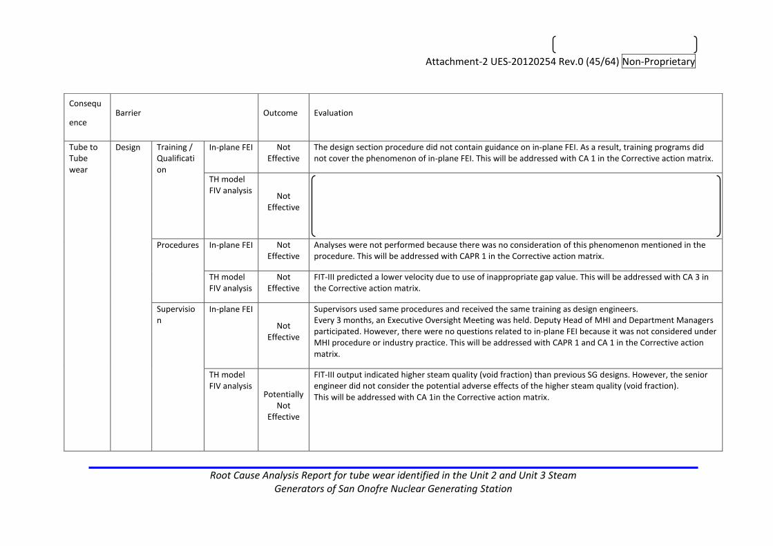
Attachment-2 UES-20120254 Rev.0 (45/64) Non-Proprietary
Root Cause Analysis Report for tube wear identified in the Unit 2 and Unit 3 Steam Generators of San Onofre Nuclear Generating Station
Consequ
ence Barrier Outcome Evaluation
Tube to Tube wear
Design Training / Qualification
In-plane FEI Not Effective
The design section procedure did not contain guidance on in-plane FEI. As a result, training programs did not cover the phenomenon of in-plane FEI. This will be addressed with CA 1 in the Corrective action matrix.
TH model FIV analysis
Not Effective
Procedures In-plane FEI Not Effective
Analyses were not performed because there was no consideration of this phenomenon mentioned in the procedure. This will be addressed with CAPR 1 in the Corrective action matrix.
TH model FIV analysis
Not Effective
FIT-III predicted a lower velocity due to use of inappropriate gap value. This will be addressed with CA 3 in the Corrective action matrix.
Supervision
In-plane FEI
Not Effective
Supervisors used same procedures and received the same training as design engineers. Every 3 months, an Executive Oversight Meeting was held. Deputy Head of MHI and Department Managers participated. However, there were no questions related to in-plane FEI because it was not considered under MHI procedure or industry practice. This will be addressed with CAPR 1 and CA 1 in the Corrective action matrix.
TH model FIV analysis
Potentially Not
Effective
FIT-III output indicated higher steam quality (void fraction) than previous SG designs. However, the senior engineer did not consider the potential adverse effects of the higher steam quality (void fraction). This will be addressed with CA 1in the Corrective action matrix.

Attachment-2 UES-20120254 Rev.0 (46/64) Non-Proprietary
Root Cause Analysis Report for tube wear identified in the Unit 2 and Unit 3 Steam Generators of San Onofre Nuclear Generating Station
Retainer
to tube
bar wear
Design Training Required Analyses
Not Effective
Necessary analyses for each component were selected based on engineering judgment and past success. Training was insufficient. This will be addressed with CAPR2in the Corrective action matrix.
Procedures Required Analyses
Not Effective
There was no requirement to confirm the consideration of a FIV analysis for changes made to a component in the flow stream. This will be addressed with CA 2in the Corrective action matrix.
Supervision Not
Effective
Based on past successful experience, engineering did not recognize the need to perform additional analysis for the retainer bars. The senior engineer did not identify the need for FIV analysis during the design verification review. This will be addressed with CA 2in the Corrective action matrix.
Tube to
AVB wear
Design Training Contact force under high steam quality
Not Effective
SG design training does not discuss contact force as a control mechanism to address vibration related wear under high steam quality (void fraction) condition. This will be addressed with CA 1in the Corrective action matrix.
Procedures
Contact force under high steam quality
Not Effective
SG design procedures do not mention AVB contact force as a control mechanism to address vibration related wear under high steam quality (void fraction) condition. This will be addressed with CAPR1in the Corrective action matrix.
Consequence all Fabrication Not
applicable
The SGs were fabricated as intended. For unit 2 it was done using the normal fabrication process. For unit 3 it required divider plate failure repair. There were no causes identified associated with fabrication deviation from the design.
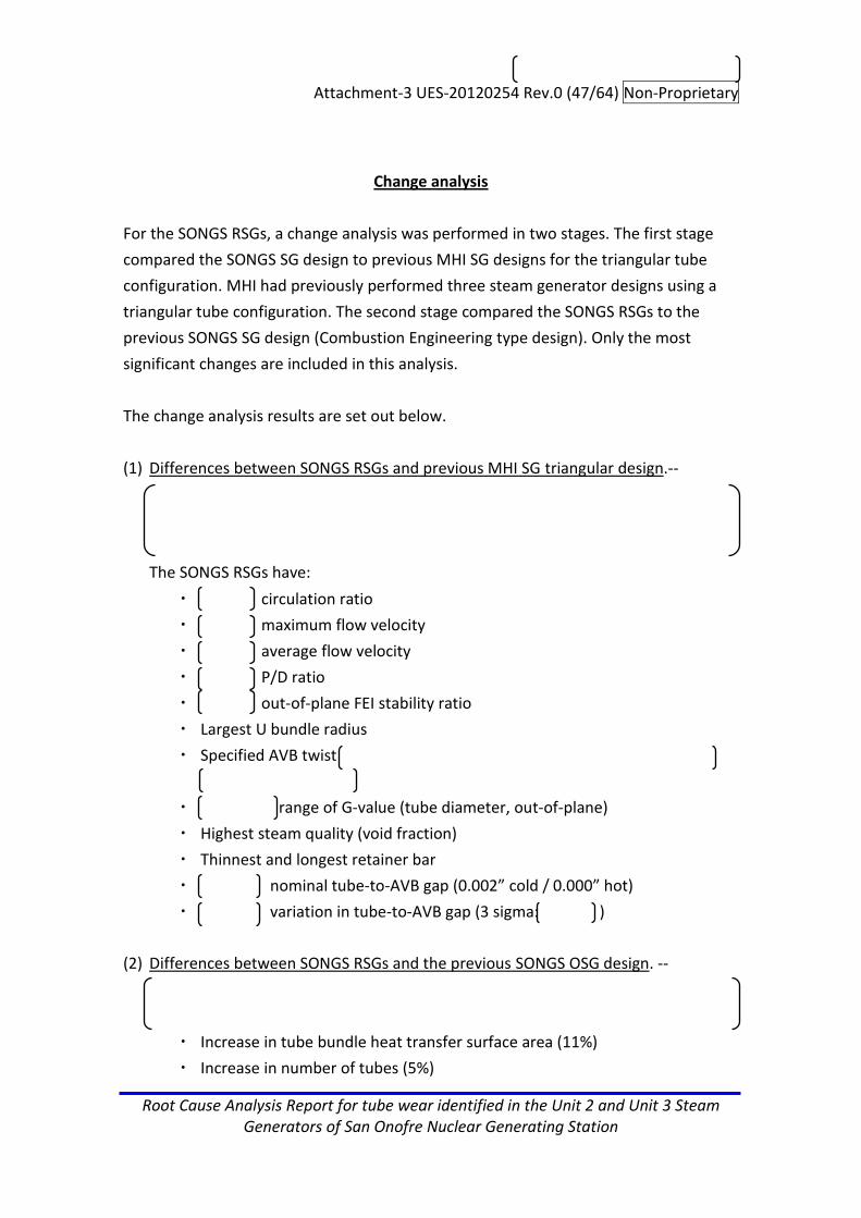
Attachment-3 UES-20120254 Rev.0 (47/64) Non-Proprietary
Root Cause Analysis Report for tube wear identified in the Unit 2 and Unit 3 Steam Generators of San Onofre Nuclear Generating Station
Change analysis
For the SONGS RSGs, a change analysis was performed in two stages. The first stage
compared the SONGS SG design to previous MHI SG designs for the triangular tube
configuration. MHI had previously performed three steam generator designs using a
triangular tube configuration. The second stage compared the SONGS RSGs to the
previous SONGS SG design (Combustion Engineering type design). Only the most
significant changes are included in this analysis.
The change analysis results are set out below.
(1) Differences between SONGS RSGs and previous MHI SG triangular design.--
The SONGS RSGs have:
・ circulation ratio
・ maximum flow velocity
・ average flow velocity
・ P/D ratio
・ out-of-plane FEI stability ratio
・ Largest U bundle radius
・ Specified AVB twist
・ range of G-value (tube diameter, out-of-plane)
・ Highest steam quality (void fraction)
・ Thinnest and longest retainer bar
・ nominal tube-to-AVB gap (0.002” cold / 0.000” hot)
・ variation in tube-to-AVB gap (3 sigma: )
(2) Differences between SONGS RSGs and the previous SONGS OSG design. --
・ Increase in tube bundle heat transfer surface area (11%)
・ Increase in number of tubes (5%)

Attachment-3 UES-20120254 Rev.0 (48/64) Non-Proprietary
Root Cause Analysis Report for tube wear identified in the Unit 2 and Unit 3 Steam Generators of San Onofre Nuclear Generating Station
・ Removal of stay cylinder
・ Change from lattice bars to trefoil broached tube support plates
・ Change in tube support configuration in U region
・ Change from CE to MHI moisture separators
・ Power level / operating temperature / tube plugging margin
(3) Identification of the changes from previous SG designs led to the recognition that
the RSG design deserved close scrutiny. MHI considered the changes in the SONGS
design from previous steam generator designs and compared the basic design
parameters of the SONGs RSGs (e.g., heat transfer area, circulation ratio, steam
pressure, etc.) with other steam generator designs. Further, as part of the
development of the SONGS RSG design, MHI conducted a detailed comparison
between its proposed AVB support for the tubes in the U-bend region and that of a
comparison plant of similar design. A special AVB team was formed and included
industry experts to conduct an extensive design review process in 2005 / 2006 to optimize
the U-bend design and address the technical issues. The team concluded that the
SONGS design was significantly more conservative than previous designs in
addressing U-bend tube vibration and wear.
Also MHI and SCE recognized that the SONGS RSG steam quality (void fraction) was
high and MHI performed feasibility studies of different methods to decrease it.
Several design adjustments were made to reduce the steam quality (void fraction)
but the effects were small. Design measures to reduce the steam quality (void
fraction) by a greater amount were considered, but these changes had
unacceptable consequences and MHI and SCE agreed not to implement them. It
was concluded that the final design was optimal based on the overall RSG design
requirements and constraints. These included physical and other constraints on the
RSG design in order to assure compliance with the provisions of 10 C.F.R. §50.59.
Thus, MHI did compare the SONGs RSG design with previous steam generator
designs, and in particular did a detailed evaluation of different options of the AVB
design taking into account other large steam generator designs.

Attachment-3 UES-20120254 Rev.0 (49/64) Non-Proprietary
Root Cause Analysis Report for tube wear identified in the Unit 2 and Unit 3 Steam Generators of San Onofre Nuclear Generating Station

Attachment-3 UES-20120254 Rev.0 (50/64) Non-Proprietary
Root Cause Analysis Report for tube wear identified in the Unit 2 and Unit 3 Steam Generators of San Onofre Nuclear Generating Station
Comparison between SONGS RSG Design and Previous MHI Designs
Operating
Conditions
SCE RSG U2 SCE RSG
U3
Comparison
to other
MHI design
Potential
Cause
Evaluation
Pressure (ata) *1
58.9 ←
Steam Flow (kg/h)
3.44E+06 ←
FW Temperature
(℃)
228 ←
S/G Level (mm)*2
1612 ←
Circulation Ratio (-) *5
3.3 ← the high steam quality (void fraction) with lower tube damping, which in combination with other factors can lead to tube vibration.
Maximum Flow Velocity (m/s) *5
← The high flow velocity provides the large dynamic pressure to the tube, which in combination with other factors can lead to tube vibration.
Average Flow velocity (m/s) *5
← The high flow velocity provides the large dynamic pressure to the tube, which in combination with other factors can lead to tube vibration.
P/D Ratio (-) 1.33 ←
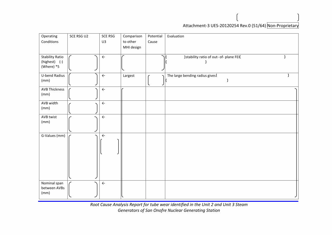
Attachment-3 UES-20120254 Rev.0 (51/64) Non-Proprietary
Root Cause Analysis Report for tube wear identified in the Unit 2 and Unit 3 Steam Generators of San Onofre Nuclear Generating Station
Operating
Conditions
SCE RSG U2 SCE RSG
U3
Comparison
to other
MHI design
Potential
Cause
Evaluation
Stability Ratio (highest) (-) (Where) *5
← stability ratio of out- of- plane FEI
U-bend Radius (mm)
← Largest The large bending radius gives
AVB Thickness (mm)
←
AVB width (mm)
←
AVB twist (mm)
←
G-Values (mm)
←
Nominal span between AVBs (mm)
←

Attachment-3 UES-20120254 Rev.0 (52/64) Non-Proprietary
Root Cause Analysis Report for tube wear identified in the Unit 2 and Unit 3 Steam Generators of San Onofre Nuclear Generating Station
Operating
Conditions
SCE RSG U2 SCE RSG
U3
Comparison
to other
MHI design
Potential
Cause
Evaluation
Natural Frequency (Hz) (tubes of Concern) *4
← .
Steam Quality (Void Fraction) (-) *5
0.9 (0.996)
← Highest Y The high steam quality (void fraction) gives the low tube damping, which in combination with other factors can lead to tube vibration.
AVB design *3 Solid type ←
Retainer bar dimension
← Thinnest Y The thinnest and longest retainer bar gives a low frequency, so FIV of retainer bar may result.
← Longest
*1 This parameter shows secondary pressure. *2 The distance between the U-bend top to water level. *3 This parameter shows RSG AVB. *4 The lowest natural frequency of tube is provided *5 Circulation ratio is obtained from SSPC code, and Max. flow vel., Avg. flow vel., stability ratio, and steam quality (void fraction) are obtained ATHOS code.

Attachment-3 UES-20120254 Rev.0 (53/64) Non-Proprietary
Root Cause Analysis Report for tube wear identified in the Unit 2 and Unit 3 Steam Generators of San Onofre Nuclear Generating Station
Comparison between SONGS RSG and Previous SONGS (CE) SG (OSG) Design*1,2
Design Element OSG Specification RSG Specification Potential Cause
Evaluation
Number of Tubes
9350 9727
Channel Head and Tubesheet Configuration
Stay cylinder to support tubesheet, floating divider plate
Thick welded structural divider plate
Tube Support Configuration (U-Bend Section)
Batwing assembly, diagonal and vertical strips with interlocking horizontal strips between tubes, lattice bars attached to structural members (shroud) external to the tube bundle
Floating structure consisting of 6 V-shaped anti-vibration bars (AVBs) with 12 support points, retaining bars, bridges, and retainer bars
Tube Support Configuration (Straight Section)
Lattice bars (egg crates) positioned by tie rods and wedge-welded to the shroud after alignment with tubesheet, shroud is active part of radial load path, 2-inch line contact on 2 sides, 1-inch line contact on 2 sides
7 trefoil broached tube support plates (TSPs) positioned by stay rods, radial load path at all TSPs
*1 This analysis focused on mechanical differences because T/H conditions were expected to be similar. *2 Five design elements listed above were obtained from MPR report ‘Original Steam Generator and Replacement Steam Generator Design Feature/Change Evaluation’.

Attachment-4 UES-20120254 Rev.0 (54/64) Non-Proprietary
Root Cause Analysis Report for tube wear identified in the Unit 2 and Unit 3 Steam Generators of San Onofre Nuclear Generating Station
RCA charter
Title: Root Cause Analysis Report for tube wear identified in the Unit 2 and Unit 3 Steam Generators of San Onofre Nuclear Generating Station
Management Sponsor: Team:
Problem Statement:
(1) Requirement No Primary-to-Secondary Leakage due to Defects in any of the RSG Units for the duration of the Warranty Period. (per 17.2.3 of General T&C with EMS)
(2) Deviation Unit 3 SG-B (SCE SG088) experienced tube leakage during operation and failure of eight tubes during in-situ pressure testing. (Both due to Defects)
(3) Consequences (For MHI)
・ 10CFR21 Report required
Timeline and Deliverables:
・ RCA Team Assigned : March 23, 2012
・ Problem Statement committed : March 23, 2012
・ Prepare begun: March 26, 2012
・ DRAFT Cause-effect analysis : April13, 2012
・ DRAFT RCA Summary : July5, 2012
・ Review RCA Summary : July7, 2012
・ DRAFT RCA Report : July20, 2012
・ Review Revised RCA Summary : August30, 2012
・ Review RCA report: September 6 and 11, 2012
・ RCA Due Date: October12, 2012
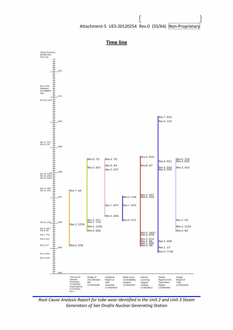
Attachment-5 UES-20120254 Rev.0 (55/64) Non-Proprietary
Root Cause Analysis Report for tube wear identified in the Unit 2 and Unit 3 Steam Generators of San Onofre Nuclear Generating Station
Time line
2012
2011
Rev.7, 3/12
2010 Rev.6, 1/15
2009
Rev.9, 8/29Rev.5, 7/3 Rev.4, 7/3 Rev.5, 7/14
Rev.5, 6/11 Rev.4, 6/12
Rev.3, 4/4 Rev.8, 4/7Rev.4, 3/21 Rev.4, 3/24 Rev.3, 3/14
Rev.2, 2/27 Rev.3, 2/292008
Rev.2, 4/6
Rev.7, 2/272007 Rev.2, 1/19 Rev.6, 1/23
Rev.1, 8/22 Rev.1, 9/20
Rev.0, 4/26
Rev.3, 2/17 Rev.0, 2/17 Rev.2, 2/3Rev.10, 1/26 2006 Rev.2, 1/19
Rev.1, 12/19Rev.1, 11/25 Rev.1, 11/14
Rev.9, 10/17
Rev.0, 9/30 Rev.0, 9/5Rev.5, 10/21Rev.4, 9/29
Rev.3, 6/24Rev.2, 6/6 Rev.2, 4/29Rev.1, 4/29
Rev.0, 2/28 Rev.0, 3/92005 Rev.1, 1/7
Rev.0, 11/30
2004
Thermal and
Hydraulic
Parameters
L5-04GA503
Superseded by
L5-04GA510
Rev.1
Design of
Anti-Vibration
Bar
L5-04GA428
Analytical
Report of
AVB
Assembly
L5-04GA419
Water Level
Controllability
Analysis
L5-04GA519
Data for
Licensing
Support
Analysis
L5-04GA511
Design
Report for the
Tube Sheet
Region
L5-04GA401
Design
Report of
Tube
L5-04GA418
Rev.3, 8/23
Rv.4, 10/22
Rev.5, 2/7
Rev.7, 7/13
Rev.8, 9/9
Rev.11, 4/12Rev.12, 4/26
Rev.13, 10/19Rev.14, 10/23Rev.15, 12/21
Rev.16, 2/5Rev.17, 2/12
Rev.18, 11/24
Rev.0, 5/31
(Replaced
with 5BBB60-
N01)
Design Procedure
(BKA60-N01)
Time Line
Rev.6, 5/17

Attachment-5 UES-20120254 Rev.0 (56/64) Non-Proprietary
Root Cause Analysis Report for tube wear identified in the Unit 2 and Unit 3 Steam Generators of San Onofre Nuclear Generating Station
2012
2011
2010 Rev.4, 1/25
2009
Rev.9, 9/25Rev.3, 8/4 Rev.8, 8/20
Rev.7, 6/4
Rev.6, 4/4Rev.7, 3/19
Rev.5, 2/29 Rev.2, 2/282008
Rev.6, 4/2
Rev.5, 2/132007
Rev.4, 12/12Rev.3, 11/17
Rev.4, 5/12Rev.3, 4/19Rev.2, 3/24
Rev.10, 1/26 2006 Rev.2, 1/19 Rev.1, 1/20
Rev.1, 11/11 Rev.0, 11/18Rev.9, 10/17 Rev.4, 10/7 Rev.2, 10/5
Rev.0, 9/30 Rev.1, 9/9 Rev.3, 9/7Rev.1, 8/5 Rev.1, 8/12
Rev.3, 7/29Rev.0, 6/27 Rev.2, 6/14 Rev.0, 6/27
Rev.2, 5/17
Rev.1, 3/9 Rev.1, 3/23Rev.0, 2/24
2005 Rev.0, 1/21 Rev.0, 1/19
2004
Material
Selection
Report for
Anti-Vibration
Bar
L5-04GA224
Material
Selection
Report for
Heat Transfer
Tubing
L5-04GA208
Material
Selection
Report for
Tube Support
Plate
L5-04GA223
Design
Report of
Tube Support
Plate and
Stay Rod
L5-04GA411
Basic Sizing
Calculation
Report
L5-04GA421
Design of
Tube Support
Plate
L5-04GA425
Qualification
Report of
AVB End Cap
L5-04GA429
Rev.3, 8/23
Rv.4, 10/22
Rev.5, 2/7
Rev.7, 7/13
Rev.8, 9/9
Rev.11, 4/12Rev.12, 4/26
Rev.13, 10/19Rev.14, 10/23Rev.15, 12/21
Rev.16, 2/5Rev.17, 2/12
Rev.18, 11/24
Rev.0, 5/31
(Replaced
with 5BBB60-
N01)
Design Procedure
(BKA60-N01)
Time Line
Rev.6, 5/17

Attachment-5 UES-20120254 Rev.0 (57/64) Non-Proprietary
Root Cause Analysis Report for tube wear identified in the Unit 2 and Unit 3 Steam Generators of San Onofre Nuclear Generating Station
2012
2011
2010
2009
Rev.5, 11/12Rev.4, 10/28
Rev.3, 8/29
Rev.2, 3/31
2008 Rev.1, 1/31
Rev.0, 8/3
2007
Rev.2, 10/18 Rev.2, 10/18 Rev.2, 10/18
Rev.1, 8/22
Rev.1, 6/13 Rev.1, 6/13 Rev.1, 6/13
Rev.10, 1/26 2006
Rev.0, 11/11 Rev.0, 11/11 Rev.0, 11/11 Rev.0, 11/11 Rev.0, 11/11 Rev.0, 11/11Rev.9, 10/17
2005
2004
Thermal and
Hydraulic
Parametric
Calculations
L5-04GA510
Anti-Vibration
Bar Assembly
1/9
L5-04FU111
Anti-Vibration
Bar Assembly
2/9
L5-04FU112
Anti-Vibration
Bar Assembly
3/9
L5-04FU113
Anti-Vibration
Bar Assembly
4/9
L5-04FU114
Anti-Vibration
Bar Assembly
5/9
L5-04FU115
Anti-Vibration
Bar Assembly
6/9
L5-04FU116
Rev.3, 8/23
Rv.4, 10/22
Rev.5, 2/7
Rev.7, 7/13
Rev.8, 9/9
Rev.11, 4/12Rev.12, 4/26
Rev.13, 10/19Rev.14, 10/23Rev.15, 12/21
Rev.16, 2/5Rev.17, 2/12
Rev.18, 11/24
Rev.0, 5/31
(Replaced
with 5BBB60-
N01)
Design Procedure
(BKA60-N01)
Time Line
Rev.6, 5/17

Attachment-5 UES-20120254 Rev.0 (58/64) Non-Proprietary
Root Cause Analysis Report for tube wear identified in the Unit 2 and Unit 3 Steam Generators of San Onofre Nuclear Generating Station
2012
2011
2010
2009
2008
Rev.9, 3/9
2007 Rev.8, 12/8Rev.7, 12/5Rev.6, 11/9Rev.5, 10/18Rev.4, 9/26 Rev.3, 9/4Rev.3, 8/24
Rev.2, 6/13
Rev.3, 4/6
Rev.1, 2/28 Rev.2, 2/17Rev.10, 1/26 2006 Rev.1, 1/19 Rev.1, 1/19
Rev.2, 12/2Rev.0, 11/11 Rev.0, 11/11 Rev.0, 11/11
Rev.9, 10/17
Rev.1, 8/12
Rev.0, 5/27
2005
Rev.3, 8/10 Rev.3, 8/10Rev.2, 7/24 Rev.2, 7/24Rev.1, 6/8 Rev.1, 6/8
Rev.0, 2/15 Rev.0, 2/15 Rev.0, 2/152004
Anti-Vibration
Bar Assembly
7/9
L5-04FU117
Anti-Vibration
Bar Assembly
8/9
L5-04FU118
Anti-Vibration
Bar Assembly
9/9
L5-04FU119
Tube Support
Plate
Assembly 3/3
L5-04FU108
General
Assembly 1/3
KAZ-04-0021
General
Assembly 2/3
KAZ-04-0022
General
Assembly 3/3
KAZ-04-0023
Rev.3, 8/23
Rv.4, 10/22
Rev.7, 7/13
Rev.8, 9/9
Rev.11, 4/12Rev.12, 4/26
Rev.13, 10/19Rev.14, 10/23Rev.15, 12/21
Rev.16, 2/5Rev.17, 2/12
Rev.18, 11/24
Rev.0, 5/31
(Replaced
with 5BBB60-
N01)
Design Procedure
(BKA60-N01)
Time Line
Rev.5, 2/7
Rev.6, 5/17
Dimesion change of
Retainer Bar
Stress Engineer sign off
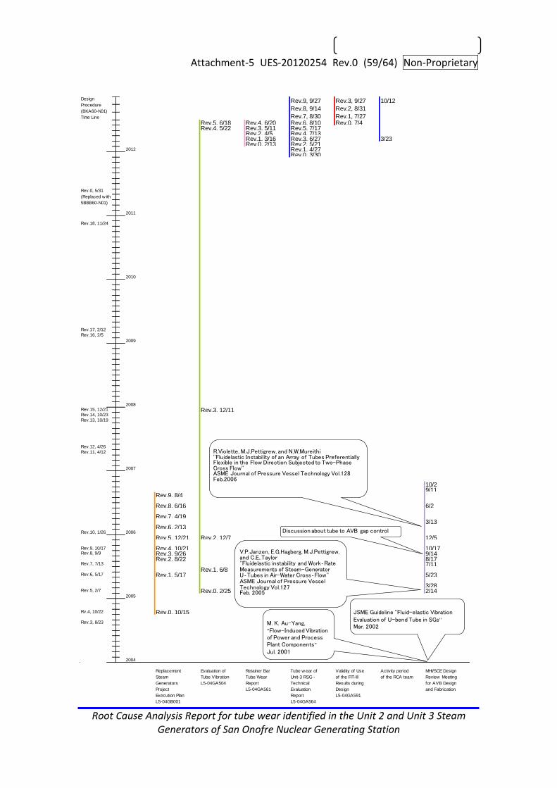
Attachment-5 UES-20120254 Rev.0 (59/64) Non-Proprietary
Root Cause Analysis Report for tube wear identified in the Unit 2 and Unit 3 Steam Generators of San Onofre Nuclear Generating Station
Rev.9, 9/27 Rev.3, 9/27 10/12
Rev.8, 9/14 Rev.2, 8/31
Rev.7, 8/30 Rev.1, 7/27Rev.5, 6/18 Rev.4, 6/20 Rev.6, 8/10 Rev.0, 7/4Rev.4, 5/22 Rev.3, 5/11 Rev.5, 7/17
Rev.2, 4/5 Rev.4, 7/13Rev.1, 3/16 Rev.3, 6/27 3/23Rev.0, 2/13 Rev.2, 5/21
2012 Rev.1, 4/27Rev.0, 3/30
2011
2010
2009
2008
Rev.3, 12/11
2007
10/29/11
Rev.9, 8/4
Rev.8, 6/16 6/2
Rev.7, 4/193/13
Rev.6, 2/13Rev.10, 1/26 2006
Rev.5, 12/21 Rev.2, 12/7 12/5
Rev.9, 10/17 Rev.4, 10/21 10/17Rev.3, 9/26 9/14Rev.2, 8/22 8/17
7/11Rev.1, 6/8
Rev.1, 5/17 5/23
3/28Rev.0, 2/25 2/14
2005
Rev.0, 10/15
2004
Replacement
Steam
Generators
Project
Execution Plan
L5-04GB001
Evaluation of
Tube Vibration
L5-04GA504
Retainer Bar
Tube Wear
Report
L5-04GA561
Tube w ear of
Unit-3 RSG -
Technical
Evaluation
Report
L5-04GA564
Validity of Use
of the FIT-III
Results during
Design
L5-04GA591
Activity period
of the RCA team
MHI/SCE Design
Review Meeting
for AVB Design
and Fabrication
Rev.3, 8/23
Rev.6, 5/17
Rv.4, 10/22
Rev.5, 2/7
Rev.8, 9/9
Rev.7, 7/13
Rev.12, 4/26
Rev.11, 4/12
Rev.14, 10/23
Rev.13, 10/19
Rev.16, 2/5
Rev.18, 11/24
Rev.17, 2/12
Rev.15, 12/21
Design
Procedure
(BKA60-N01)
Time Line
Rev.0, 5/31
(Replaced w ith
5BBB60-N01)
R.Violette, M.J.Pettigrew, and N.W.Mureithi''Fluidelastic Instability of an Array of Tubes Preferentially Flexible in the Flow Direction Subjected to Two-Phase Cross Flow''ASME Journal of Pressure Vessel Technology Vol.128Feb.2006
V.P.Janzen, E.G.Hagberg, M.J.Pettigrew, and C.E..Taylor''Fluidelastic instability and Work‐Rate Measurements of Steam-Generator U‐Tubes in Air-Water Cross‐Flow''ASME Journal of Pressure Vessel Technology Vol.127Feb. 2005
Discussion about tube to AVB gap control
M. K. Au-Yang,''Flow-Induced Vibration of Power and Process Plant Components''
Jul. 2001
JSME Guideline ''Fluid-elastic Vibration Evaluation of U-bend Tube in SGs''
Mar. 2002

Attachment-6 UES-20120254 Rev.0 (60/64) Non-Proprietary
Root Cause Analysis Report for tube wear identified in the Unit 2 and Unit 3 Steam Generators of San Onofre Nuclear Generating Station
Interview list

Attachment-6 UES-20120254 Rev.0 (61/64) Non-Proprietary
Root Cause Analysis Report for tube wear identified in the Unit 2 and Unit 3 Steam Generators of San Onofre Nuclear Generating Station

Attachment-7 UES-20120254 Rev.0 (62/64) Non-Proprietary
Root Cause Analysis Report for tube wear identified in the Unit 2 and Unit 3 Steam Generators of San Onofre Nuclear Generating Station
Reference documents
1. 5BB60-N06Rev.1 “ASME Code Job Procedure for Preparation of Design Reports”, 5/30/2012
2. 5BBB60-N01Rev.0 “Procedure for Controlling of the Design Activities”, 5/31/2011
3. KAS-20050202 Rev.1 “FIT-III Code Description Note (Code User’s Manual)“, 11/18/2005
4. L5-04GA504 Rev.5 “Evaluation of Tube Vibration“, 6/18/2012
5. L5-04GA588 draft “Summary of Technical Evaluation“
6. L5-04GA561 Rev.4 “Retainer Bar Tube Wear Report“, 6/20/2012
7. L5-04GA564 Rev.9 “Tube wear of Unit-3 RSG - Technical Evaluation Report“, 9/27/2012
8. L5-04GA591Rev.3 “Validity of Use of the FIT-III Results during Design“, 9/27/2012
9. L5-04GA428 Rev.5 “Design of Anti-Vibration Bar”, 7/3/2008
10. L5-04GA419 Rev.4 “Analytical Report of AVB Assembly”, 7/3/2008
11. L5-04GA519Rev.2 “Water Level Controllability Analysis”, 1/19/2007
12. L5-04GA511 Rev.9 “Data for Licensing Support Analysis”, 8/29/2008
13. L5-04GA401 Rev.7 “Design Report for the Tube Sheet Region”, 3/12/2010
14. L5-04GA418 Rev.5 “Design Report of Tube”, 7/14/2008
15. L5-04GA224 Rev.2 “Material Selection Report for Anti-Vibration Bar”, 1/19 2006
16. L5-04GA208 Rev.3 “Material Selection Report for Heat Transfer Tubing”,7/29/2005
17. L5-04GA223 Rev.1 “Material Selection Report for Tube Support Plate”, 9/9/2005
18. L5-04GA411 Rev.7 “Design Report of Tube Support Plate and Stay Rod”, 6/4/2008
19. L5-04GA421 Rev.4 “Basic Sizing Calculation Report”, 1/25/2010
20. L5-04GA425 Rev.9 “Design of Tube Support Plate”, 9/25/2008
21. L5-04GA429 Rev.4 “Qualification Report of AVB End Cap”, 5/12/2006
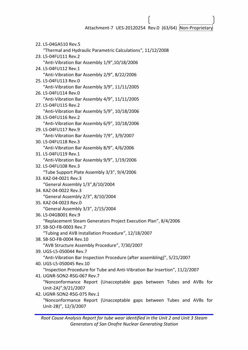
Attachment-7 UES-20120254 Rev.0 (63/64) Non-Proprietary
Root Cause Analysis Report for tube wear identified in the Unit 2 and Unit 3 Steam Generators of San Onofre Nuclear Generating Station
22. L5-04GA510 Rev.5 “Thermal and Hydraulic Parametric Calculations“, 11/12/2008
23. L5-04FU111 Rev.2 “Anti-Vibration Bar Assembly 1/9”,10/18/2006
24. L5-04FU112 Rev.1 “Anti-Vibration Bar Assembly 2/9”, 8/22/2006
25. L5-04FU113 Rev.0 “Anti-Vibration Bar Assembly 3/9”, 11/11/2005
26. L5-04FU114 Rev.0 “Anti-Vibration Bar Assembly 4/9”, 11/11/2005
27. L5-04FU115 Rev.2 “Anti-Vibration Bar Assembly 5/9”, 10/18/2006
28. L5-04FU116 Rev.2 “Anti-Vibration Bar Assembly 6/9”, 10/18/2006
29. L5-04FU117 Rev.9 “Anti-Vibration Bar Assembly 7/9”, 3/9/2007
30. L5-04FU118 Rev.3 “Anti-Vibration Bar Assembly 8/9”, 4/6/2006
31. L5-04FU119 Rev.1 “Anti-Vibration Bar Assembly 9/9”, 1/19/2006
32. L5-04FU108 Rev.3 “Tube Support Plate Assembly 3/3”, 9/4/2006
33. KAZ-04-0021 Rev.3 “General Assembly 1/3”,8/10/2004
34. KAZ-04-0022 Rev.3 “General Assembly 2/3”, 8/10/2004
35. KAZ-04-0023 Rev.0 “General Assembly 3/3”, 2/15/2004
36. L5-04GB001 Rev.9 “Replacement Steam Generators Project Execution Plan”, 8/4/2006
37. SB-SO-FB-0003 Rev.7 “Tubing and AVB Installation Procedure”, 12/18/2007
38. SB-SO-FB-0004 Rev.10 “AVB Structure Assembly Procedure”, 7/30/2007
39. UGS-L5-050044 Rev.7 “Anti-Vibration Bar Inspection Procedure (after assembling)”, 5/21/2007
40. UGS-L5-050045 Rev.10 “Inspection Procedure for Tube and Anti-Vibration Bar Insertion”, 11/2/2007
41. UGNR-SON2-RSG-067 Rev.7 “Nonconformance Report (Unacceptable gaps between Tubes and AVBs for Unit-2A)”,9/21/2007
42. UGNR-SON2-RSG-075 Rev.1 “Nonconformance Report (Unacceptable gaps between Tubes and AVBs for Unit-2B)”, 12/3/2007

Attachment-7 UES-20120254 Rev.0 (64/64) Non-Proprietary
Root Cause Analysis Report for tube wear identified in the Unit 2 and Unit 3 Steam Generators of San Onofre Nuclear Generating Station
43. UGNR-SON3-RSG-024 Rev.1 “Nonconformance Report for some Gaps between Tubes and AVBs are larger than the criterion”, 4/24/2008
44. UGNR-SON3-RSG-030 Rev.0 “Nonconformance Report for some Gaps between Tubes and AVBs are larger than the criterion”,3/20/2008

Non-proprietary Version (1/68)
CONTENT
DESCRIPTION
FIGURE
TOTAL
Dis
trib
utio
n
SHEET
PAGE
PAGE
-
-
68
REMARKS
PURCHASER
ORDER No.
ITEM No.
2591012
2000
DATE
REFERENCE
0
DWG. No.
L5-04GA588
Rev.No.
Nuclear Plant Component Designing Department
Steam Generator Designing Section
Supplemental Technical Evaluation Report
San Onofre Nuclear Generating Station, Units 2 & 3 REPLACEMENT STEAM GENERATORS
PM
(S)
1
CO
PY
1
CHECKED BY
DESIGNED BY
APPROVED BY
―――
ISSUE DATE
DRAWN BY
―――
―――
MITSUBISHI HEAVY INDUSTRIES, LTD.
Specification No. SO23-617-01R3
Purchase Order No. 4500024051
Edison (MNES)

(2/68) Document No.L5-04GA588(0)
MITSUBISHI HEAVY INDUSTRIES, LTD.
Non-proprietary Version
Revision History
No. Revision Date Approved Checked Prepared
0 Initial issue See cover sheet

(3/68) Document No.L5-04GA588(0)
MITSUBISHI HEAVY INDUSTRIES, LTD.
Non-proprietary Version
Contents
1. Introduction .............................................................................................................. 4
2. Wear Mechanism of Type 1 (Tube-to-tube wear) .................................................... 6
2.1 Tube Wear Indications of Type 1 (Tube-to-tube wear) .......................................... 6
2.2 Causes of Type 1 Tube Wear (Tube-to-Tube wear) ............................................ 12
2.3 FEI ....................................................................................................................... 13
2.3.1 Conditions Necessary for FEI ....................................................................... 14
2.3.2 Critical Factor (K) for the SONGS RSGs ...................................................... 16
2.3.3 Natural Frequency / Support Conditions / Contact Force ............................. 17
2.3.4 Thermal Hydraulic Conditions and Tube Damping ....................................... 21
2.4 Conclusion .......................................................................................................... 28
3. Wear Mechanism of Type 2 (AVB wear) ................................................................ 29
3.1 Tube Wear Indications of Type 2 (AVB wear) ...................................................... 29
3.2 Tube-to-AVB Wear Experience in Other Large CE-Plant RSGs ......................... 34
3.3 Causes of Type 2 Tube Wear (Tube-to-AVB wear) ............................................. 38
3.3.1 Evaluation of U-bend Support Conditions .................................................... 39
3.3.2 Secondary Side Thermal Hydraulic Conditions ............................................ 42
3.4 Out-of-plane FEI is not the cause of AVB wear ................................................... 43
3.5 Relationship between Random Vibration and In-plane FEI ................................ 47
3.6 Conclusion .......................................................................................................... 50
4. Design Approach ................................................................................................... 51
4.1 Design Approach (circa 2005-06) ........................................................................ 51
4.1.1 General Design and Performance Requirements ......................................... 51
4.1.2 U-bend Design Approach for Vibration Control ............................................ 51
4.1.3 Evaluation of Design Changes to Reduce Void Fraction .............................. 56
4.2 U-bend Design Approach (circa 2012) ................................................................ 56
4.2.1 A New Paradigm ........................................................................................... 56
4.2.2 Assessment of the New Paradigm ................................................................ 57
4.2.3 Design Implications of the New Paradigm .................................................... 58
5. References ............................................................................................................ 60
Appendix-1 .................................................................................................................... 61
Appendix-2 .................................................................................................................... 64
Appendix-3 .................................................................................................................... 66

(4/68) Document No.L5-04GA588(0)
MITSUBISHI HEAVY INDUSTRIES, LTD.
Non-proprietary Version
Preface
This Supplemental Technical Evaluation summarizes the information contained in the
report “Tube wear of Unit 3 RSG – Technical Evaluation Report” (L5-04GA564 latest
revision, Ref. 1) (“TER”) and supplements it with information taken from other MHI
documents and the AREVA Operational Assessment and with further analysis. It is
intended as a guide and introduction to the main findings of the TER as well as an
explanation of key information from related documents.
1. Introduction
On January 31, 2012, during the first cycle after steam generator replacement, San
Onofre Nuclear Generating Station (SONGS) Unit 3 was shut down to investigate a
steam generator tube leak. Steam generator tube inspections confirmed a small leak in
one tube in one of the two steam generators. Further inspections of 100% of the steam
generator tubes in both Unit 3 steam generators discovered unexpected wear, including
tube-to-tube as well as tube-to-tube-support wear. At the time of the Unit 3 leak,
SONGS Unit 2 had already completed one cycle of power operation (~22 months) and
was in a refueling outage. Inspections of tubes in the Unit 2 steam generators revealed
similar wear to that found in Unit 3.
The detailed inspections revealed tube wear in the tube free span sections, at
anti-vibration bars (AVBs), at tube support plates (TSPs), and at retainer bars. These
indications were labeled as follows:
(i) Type 1 (Tube-to-Tube Wear)
(ii) Type 2 (AVB wear without Tube-to-Tube wear)
(iii) Type 3 (TSP wear without Tube-to-Tube wear or AVB wear)
(iv) Type 4 (Retainer bar wear)
The cause of the first 3 types of tube wear is tube vibration. Type 4 tube wear is caused
by vibration of the retainer bars.
The causes of tube vibration are (1) insufficient support for the tubes in the in-plane
direction caused by small and uniform tube-to-AVB clearances, and (2) localized high
thermal-hydraulic conditions in the SG secondary side. The mechanistic causes of the
first three types of tube wear are described in detail in the TER (Ref. 1). The

(5/68) Document No.L5-04GA588(0)
MITSUBISHI HEAVY INDUSTRIES, LTD.
Non-proprietary Version
mechanistic causes of Type 4 wear (not discussed in this document) are described in
the “Retainer Bar Tube Wear Report” (L5-04GA561 latest revision, Ref. 2).
The numbers of tubes for each type of tube wear in the Unit 2 and Unit 3 steam
generators are listed in Table 1-1 and Table 1-2. These numbers are based on the MHI
database (refer to “Screening Criteria for Susceptibility to In-Plane Tube Motion”
(L5-04GA571 latest revision (Ref. 3), Appendix 3). The MHI database numbers differ
from those of the SCE database as explained in TER Section 4.1 (Ref. 1).
Table 1-1 Number of Tubes with Wear in SONGS Unit 2
Wear Type SG 2A
(2E-089)
SG 2B
(2E-088) Total
Type 1 (TTW) 2 (note 2) 0 2 (note 2)
Type 2 (AVB wear) 802 595 1397
Type 3 (TSP wear) 53 137 190
Type 4 (RB wear) 4 2 6
Foreign Object 0 2 2
Total 861 736 1597
Notes:
1) Each tube is only counted once, with the priority given to Type 1 followed by
Type 2, Type 3, Type 4 and Foreign Object.
2) The wear characteristics of these two tubes differ from the TTW tubes in Unit 3
in that they exhibit no wear at the top TSP and only contact each other at a
single point.
Table 1-2 Number of Tubes with Wear in SONGS Unit 3
Wear Type SG 3A
(3E-089)
SG 3B
(3E-088) Total
Type 1 (TTW) 165 161 326
Type 2 (AVB wear) 714 737 1451
Type 3 (TSP wear) 15 20 35
Type 4 (RB wear) 1 3 4
Foreign Object 0 0 0
Total 895 921 1816
Notes:
(6/68) Document No.L5-04GA588(0)
MITSUBISHI HEAVY INDUSTRIES, LTD.
Non-proprietary Version
1) Each tube is only counted once with the priority given to Type 1 followed by
Type 2, Type 3, and Type 4.
2. Wear Mechanism of Type 1 (Tube-to-tube wear)
2.1 Tube Wear Indications of Type 1 (Tube-to-tube wear)
The Type 1 wear pattern is found in the tube free-span sections between or crossing
over the AVBs. Type 1 wear can be differentiated from Type 2 wear by its location on the
circumference of the tube. Type 2 wear is located on the sides of the tube that are
adjacent to the AVBs while Type 1 wear is located on the extrados or intrados of the
tube (the top or bottom of the tube cross section). Type 1 and Type 2 wear can be
distinguished from each other by rotating ECT.
Type 1 tube to tube wear occurs when there is tube in-plane motion (vibration) with a
displacement (amplitude) greater than the distance between the tubes in the adjacent
rows, resulting in tube-to-tube contact.1 These tubes also exhibit significant wear at the
AVBs and TSPs in addition to the free-span wear. Tubes with Type 1 wear are shown in
Fig. 2.1-1 (Unit 2) and Fig. 2.1-2 (Unit 3). These figures display the same data as shown
in Fig.4.1.1-1 in the TER (Ref. 1).
The AREVA Operational Assessment (Ref. 4) at page 16 states:
Both steam generators in Unit 3 had more than 160 tubes with TTW indications
in U-bends. The three most degraded tubes exhibited wear scars that were more
than 28 inches long . . .. TTW scars are located on the extrados and intrados
locations of U-bends. Wear scars on extrados locations of a given U-bend have
matching wear scars on intrados locations of the neighboring row tube in the
same column.
1 Some of the tubes with tube-tube wear did not experience large amplitude vibration but were
impacted by tubes that did experience large amplitude vibration. Also the two tubes in Unit 2 with
tube-to-tube wear had different wear characteristics than the Unit 3 tube-to-tube wear. Neither of
the two Unit 2 tubes exhibits wear at the top TSP and neither exhibits free span wear on both the
hotleg and coldleg sides of the U-bend (the free span wear indication is only on one side of the
U-bend).
(7/68) Document No.L5-04GA588(0)
MITSUBISHI HEAVY INDUSTRIES, LTD.
Non-proprietary Version
This pattern of wear reflects large amplitude displacement of the tubes in the in-plane
direction. Those tubes with the large amplitude displacements also have significant
wear at the top tube support plate (TSP 7) (See L5-04GA571 the latest revision (Ref. 3)),
which is consistent with large displacement of tubes in the in-plane direction without
in-plane AVB support.

Non-proprietary V
ersion
MIT
SU
BIS
HI H
EA
VY
IND
US
TR
IES
, LTD
.
(8/68)D
ocument N
o.L5-04GA
588(0)
2A-SG (Unit 2 E089)
Fig 2.1-1 (1/2) Unit 2 Tubes with TTW indications
Wear depth
TTW 1~10% TTW 11~20% TTW 21~30% TTW 31~40% TTW >41%

Non-proprietary V
ersion
MIT
SU
BIS
HI H
EA
VY
IND
US
TR
IES
, LTD
.
(9/68)D
ocument N
o.L5-04GA
588(0)
2B-SG (Unit 2 E088)
Fig 2.1-1 (2/2) Unit 2 Tubes with TTW indications
Wear depth
TTW 1~10% TTW 11~20% TTW 21~30% TTW 31~40% TTW >41%

Non-proprietary V
ersion
MIT
SU
BIS
HI H
EA
VY
IND
US
TR
IES
, LTD
.
(10/68)D
ocument N
o.L5-04GA
588(0)
3A-SG (Unit 3 E089)
Fig 2.1-2 (1/2) Unit 3 Tubes with TTW indications
Row-1
Row-6
Row-11
Row-16
Row-21
Row-26
Row-31
Row-36
Row-41
Row-46
Row-51
Row-56
Row-61
Row-66
Row-71
Row-76
Row-81
Row-86
Row-91
Row-96
Row-101
Row-106
Row-111
Row-116
Row-121
Row-126
Row-131
Row-136
Row-141
1-C
ol
6-C
ol
11-C
ol
16-C
ol
21-C
ol
26-C
ol
31-C
ol
36-C
ol
41-C
ol
46-C
ol
51-C
ol
56-C
ol
61-C
ol
66-C
ol
71-C
ol
76-C
ol
81-C
ol
86-C
ol
91-C
ol
96-C
ol
101-C
ol
106-C
ol
111-C
ol
116-C
ol
121-C
ol
126-C
ol
131-C
ol
136-C
ol
141-C
ol
146-C
ol
151-C
ol
156-C
ol
161-C
ol
166-C
ol
171-C
ol
176-C
ol
LEGEND○:0%●:AVB 1 ~ 10%●:AVB 11 ~ 20%●:AVB 21 ~ 30%●:AVB 31 ~ 40%●:AVB > 41%
Wear depth
TTW 1~10% TTW 11~20% TTW 21~30% TTW 31~40% TTW >41%

Non-proprietary V
ersion
MIT
SU
BIS
HI H
EA
VY
IND
US
TR
IES
, LTD
.
(11/68)D
ocument N
o.L5-04GA
588(0)
3B-SG (Unit 3 E088)
Fig 2.1-2 (2/2) Unit 3 Tubes with TTW indications
Row-1
Row-6
Row-11
Row-16
Row-21
Row-26
Row-31
Row-36
Row-41
Row-46
Row-51
Row-56
Row-61
Row-66
Row-71
Row-76
Row-81
Row-86
Row-91
Row-96
Row-101
Row-106
Row-111
Row-116
Row-121
Row-126
Row-131
Row-136
Row-141
1-C
ol
6-C
ol
11-C
ol
16-C
ol
21-C
ol
26-C
ol
31-C
ol
36-C
ol
41-C
ol
46-C
ol
51-C
ol
56-C
ol
61-C
ol
66-C
ol
71-C
ol
76-C
ol
81-C
ol
86-C
ol
91-C
ol
96-C
ol
101-C
ol
106-C
ol
111-C
ol
116-C
ol
121-C
ol
126-C
ol
131-C
ol
136-C
ol
141-C
ol
146-C
ol
151-C
ol
156-C
ol
161-C
ol
166-C
ol
171-C
ol
176-C
ol
LEGEND○:0%●:AVB 1 ~ 10%●:AVB 11 ~ 20%●:AVB 21 ~ 30%●:AVB 31 ~ 40%●:AVB > 41%
Wear depth
TTW 1~10% TTW 11~20% TTW 21~30% TTW 31~40% TTW >41%

(12/68) Document No.L5-04GA588(0)
MITSUBISHI HEAVY INDUSTRIES, LTD.
Non-proprietary Version
2.2 Causes of Type 1 Tube Wear (Tube-to-Tube wear)
As discussed above, most of the Type 1 wear (TTW) indications suggest that the wear is
due to tube in-plane motion (vibration) with a displacement (amplitude) greater than the
distance between the tubes in the adjacent rows, resulting in tube-to-tube contact. Tube
in-plane motion can be caused by turbulence and fluid elastic instability (FEI). However,
turbulence induced (random) vibration by itself is insufficient to produce displacements
of this magnitude. Displacements as large as those associated with in-plane
tube-to-tube contact can only be produced by fluid elastic vibration. Further, the
contiguous grouping of the TTW tubes is another characteristic of fluid elastic instability
as discussed further in Section 2.3.
As discussed in Sections 5 and 6.1 of the TER, in order for large in-plane displacements
to occur two conditions are necessary. First, the tube needs to be unrestrained in the
in-plane direction and second the environment must be conducive to FEI (velocity,
density, damping, etc.). These causes are summarized in Fig.2.2-1. This figure shows
the same mechanism as Fig.6.1-1 in the TER (Ref. 1).
The following Section provides an explanation of the nature of and conditions necessary
for FEI and describes the characteristics of the SONGS RSGs that led to the occurrence
of in-plane FEI in the RSGs.

(13/68) Document No.L5-04GA588(0)
MITSUBISHI HEAVY INDUSTRIES, LTD.
Non-proprietary Version
Fig. 2.2-1 Type 1 Wear (TTW) In-Plane Mechanism
Two Phase Flow
AVB
(To Prevent Out-of-Plane Vibration)
Tube to AVB Gap
Zero Gap
Controlled to be small Gap
:Out-of-Plane Vibration
:In-Plane VibrationTubes
Two Phase Flow
AVB
(To Prevent Out-of-Plane Vibration)
Tube to AVB Gap
Zero Gap
Controlled to be small Gap
:Out-of-Plane Vibration
:In-Plane VibrationTubes
(max 0.9) 【AVB Structure】 Tube between 2 flat AVBs
・AVB Design Assumes Out-of Plane Vibration Since out-of-plane FEI is more likely to happen compared to in-plane FEI, AVBs are
placed at the sides of tube to prevent out-of-plane vibration
6 V-Shaped AVBs(12 support points) ・Number of AVB Support Points are confirmed to satisfy
ASME FEI Requirements
Designed and fabricated for effective ”Zero” Gap between Tube and AVB in hot condition

(14/68) Document No.L5-04GA588(0)
MITSUBISHI HEAVY INDUSTRIES, LTD.
Non-proprietary Version
2.3 FEI
2.3.1 Conditions Necessary for FEI
In a tube array, a momentary displacement of one tube from its equilibrium position will
alter the flow field and change the force balance on the neighboring tubes, causing them
to change their positions in a coordinated manner. When the energy extracted from the
flow by the tubes exceeds the energy dissipated by damping it produces fluid elastic
vibration. The threshold for this instability is shown in Figure 2.3-1 below, where one
axis (Y) of the graph is vibration amplitude and the other (X) is flow velocity. The curve
shows that as flow velocity increases, vibration initially increases gradually. As velocity
continues to increase, it will reach a point where the slope of the vibration line changes
abruptly. The point on the curve where the slope changes is termed the “critical
velocity”.
Figure 2.3-1 Relation between Vibration Amplitude and Flow Velocity
The Critical Velocity is a function of the tube’s natural frequency, damping, and the
Critical Factor among other parameters shown in the equation below.

(15/68) Document No.L5-04GA588(0)
MITSUBISHI HEAVY INDUSTRIES, LTD.
Non-proprietary Version
21
20
/
ooo
c
D
mK
fD
U
Where,
Uc : Critical velocity
f : Tube natural frequency
δ : Damping term
K : Critical factor
Do : Tube outside diameter
m0 : Average tube mass per unit length
ρo : Density of fluid outside the tube
This equation is based on work done by Dr. H. J. Connors, and the Critical Factor, K, is
often referred to as Connor’s constant, but as discussed in Section 7.1 of L5-04GA567
(Ref. 5), the Critical Factor may vary.
The tube natural frequency is dependent on tube geometry and tube supporting
conditions. The density of the fluid outside the tube depends on the secondary side fluid
environment. The tube outside diameter and the average tube mass per unit length are
set by the design.
For U-bend tubes in two phase flow, there are four sources of damping: structural
damping, external fluid (two-phase) damping, viscous damping and squeeze film
damping. For the SONGS RSG, the relevant sources are structural, external fluid and
squeeze film damping. Damping is discussed in more detail in Section 2.3.4 below.
The Critical Factor is an experimentally determined value, which is a function of the tube
pattern and the fluid environment. The Critical Factor varies for each tube as a function
of void fraction and location of the tube within the U-bend (See Section 7.1 of
L5-04GA567 the latest revision (Ref. 5)).
The tube natural frequency and the Critical Factor differ in the in-plane and out-of-plane
directions. For the SONGS RSG tube geometry, based on experimental data, MHI
estimates that the Critical Factor for in-plane FEI is at least 50% higher than the Critical
Factor for out-of-plane FEI (See Section 2.3.2 below for details). The tube natural

(16/68) Document No.L5-04GA588(0)
MITSUBISHI HEAVY INDUSTRIES, LTD.
Non-proprietary Version
frequencies for the in-plane and out-of-plane directions depend on the number of
supports. For U-bend SGs, when the number of supports are equal in both directions,
the U-bend natural frequency out-of-plane is lower than the U-bend natural frequency
in-plane (See Appendices 1 and 2 for details).
2.3.2 Critical Factor (K) for the SONGS RSGs
The Critical Factor for in-plane FEI can be related to the Critical Factor for out-of plane
FEI and the tube pattern pitch-to-diameter (P/D) ratio (this is discussed in more detail in
Section 7.1.1.2 of MHI’s “Evaluation of Stability Ratio for Return to Service”
L5-04GA567 latest revision (Ref. 5)). Based on its analysis and test data, MHI has
developed the following relationship reflected in the figure and table below.
Ki = k x Ko
Where,
k : Ratio of Critical Factor of In-plane FEI and Out-of-plane FEI
Ki : Best-estimate Critical Factor of In-plane FEI
Ko : Best-estimate Critical Factor of Out-of-plane FEI
Fig.2.3.2-1 Critical Factor Ratio to P/D Relationship
P/D Fluid Ratio of critical flow velocity
κ=Vc(In-plane)/Vc(Out-of-plane)
Note
1.5 Air-Water
2.7 Violette et al.(2006)
1.37 Air 1.7 Khalvatti et al.(2010)
1.2 Air 0.71 Nakamura et al.(2012)
P/D Fluid Ratio of critical flow velocity
κ=Vc(In-plane)/Vc(Out-of-plane)
Note
1.5 Air-Water
2.7 Violette et al.(2006)
1.37 Air 1.7 Khalvatti et al.(2010)
1.2 Air 0.71 Nakamura et al.(2012)

(17/68) Document No.L5-04GA588(0)
MITSUBISHI HEAVY INDUSTRIES, LTD.
Non-proprietary Version
This figure shows the relationship between the Critical Factor Ratio for in-plane /
out-of-plane FEI and the tube pitch-to-diameter ratio. The SONGS P/D ratio in most of
the tube bundle is 1.33. However, in the U-bend, where the tubes are further apart due
to straight-leg indexing, the P/D ratio increases to a maximum value at the top of the
U-bend. Thus, from Figure 2.3.2-1 it can be seen that the Critical Factor for in-plane FEI
is times as large as the Critical Factor for out-of-plane FEI for the SONGS tube
pattern (or greater where tube indexing is present). This indicates that, given identical
support conditions, the onset of out-of-plane FEI will occur much sooner than in-plane
FEI.
2.3.3 Natural Frequency / Support Conditions / Contact Force
As discussed above, tube natural frequency is dependent on tube geometry and tube
supporting conditions. Following is an analysis of the supporting conditions associated
with the Unit-3 TTW tubes.
The locations of the Unit 3 and Unit 2 TTW wear indications along the U-tube arc length
are depicted in Fig. 2.3.3-1 taken from AREVA’s “SONGS U2C17 Steam Generator
Operational Assessment for Tube-to-Tube Wear “ No. 51-9187230-000 (Ref. 4).
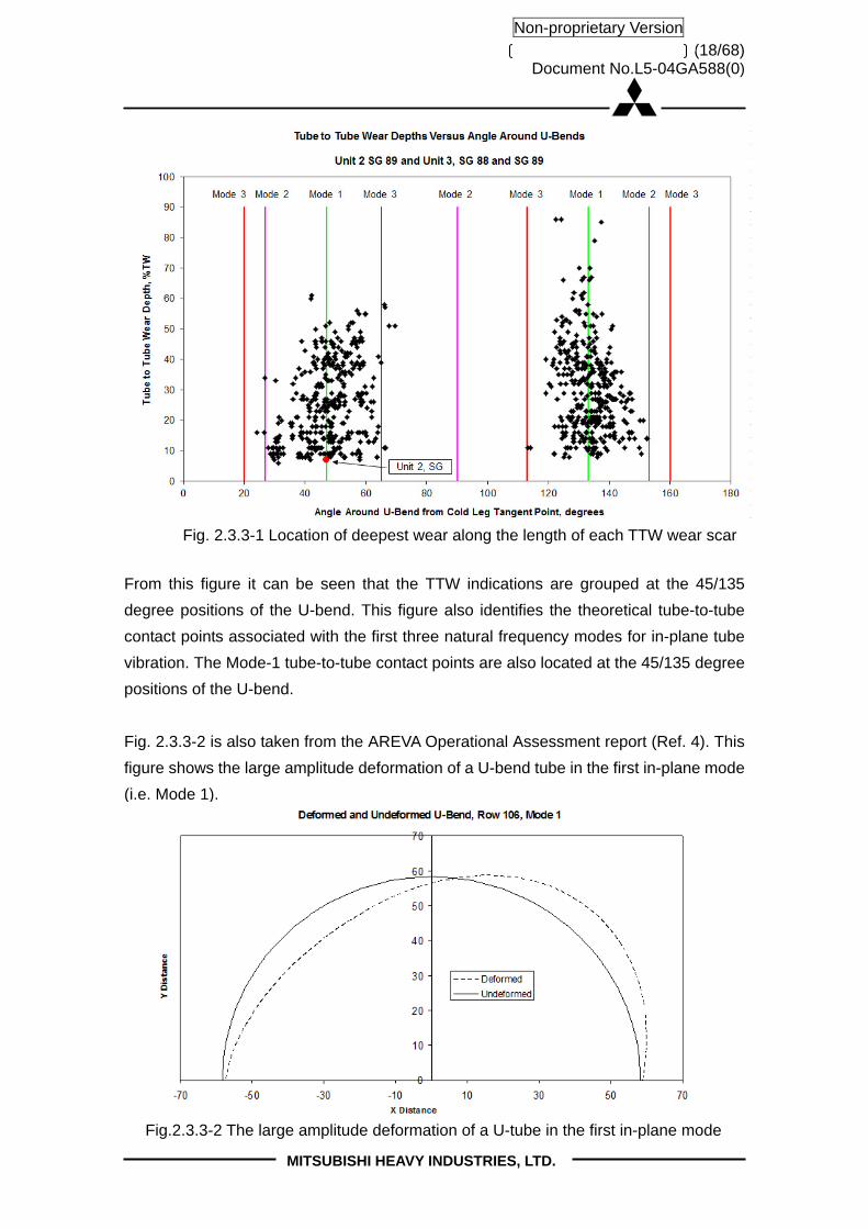
(18/68) Document No.L5-04GA588(0)
MITSUBISHI HEAVY INDUSTRIES, LTD.
Non-proprietary Version
From this figure it can be seen that the TTW indications are grouped at the 45/135
degree positions of the U-bend. This figure also identifies the theoretical tube-to-tube
contact points associated with the first three natural frequency modes for in-plane tube
vibration. The Mode-1 tube-to-tube contact points are also located at the 45/135 degree
positions of the U-bend.
Fig. 2.3.3-2 is also taken from the AREVA Operational Assessment report (Ref. 4). This
figure shows the large amplitude deformation of a U-bend tube in the first in-plane mode
(i.e. Mode 1).
Fig.2.3.3-2 The large amplitude deformation of a U-tube in the first in-plane mode
Fig. 2.3.3-1 Location of deepest wear along the length of each TTW wear scar

(19/68) Document No.L5-04GA588(0)
MITSUBISHI HEAVY INDUSTRIES, LTD.
Non-proprietary Version
In order for the tubes to touch in this in-plane mode shape, the tubes must be free of
restraint at the 12 AVB intersections and only supported at the top TSP.
For the reasons stated in the discussion of the Critical Factor in Section 2.3.2 above,
out-of-plane FEI will occur at a lower velocity threshold than in-plane FEI when the
support conditions are the same for both directions. Also, as discussed in Appendices 1
and 2, out-of-plane FEI will occur at a lower velocity threshold than in-plane FEI, when
the support conditions are the same for both directions, because the tube out-of-plane
natural frequency is lower than tube in-plane frequency. Therefore, since out-of-plane
FEI did not occur, the tube out-of-plane support must be effective (as intended by the
designers).
The absence of out-of-plane FEI and the presence of in-plane FEI can only happen
when all or most of the 24 tube-to-AVB intersections (AVB on both sides of a tube with
12 locations) have gaps small enough to be effective in the out-of-plane direction and
lack sufficient contact forces to be effective in the in-plane direction. As shown in
Appendix 2, the critical velocity threshold for in-plane FEI will occur before that for
out-of-plane FEI if the number of active supports against in-plane FEI becomes
sufficiently smaller than the number needed to prevent out-of-plane FEI.
MHI performed a comprehensive statistical evaluation of the tube-to-AVB contact forces
based on manufacturing data and concluded that the Unit 2 contact forces are
approximately double that of the Unit 3 RSGs (See Section 5.2.3 of the TER (Ref. 1)).
This offers an explanation of why almost all of the TTW indications were in the Unit 3
RSGs.
The difference in the contact forces between the Unit 2 and Unit 3 RSGs is mainly
associated with better control of the AVB and tube fabrication dimensions in the Unit 3
RSGs. As discussed in Section 5.2.3 of the TER (Ref. 1), a pressing force was
used on the Unit 3 AVBs to reduce the twist and flatness, while a pressing force
was used for the Unit 2 AVBs. Additional evidence that the Unit 3 AVB dimensions were
more uniform and that the tube-to-AVB contact forces were smaller is that the Unit 2
RSGs had more ding signals than the Unit 3 RSGs. Ding signals are evidence of tiny
marks on the tube outer surface caused by interference between AVBs and tubes.
Almost all of the Unit 2 ding signals were at the AVB nose regions.

(20/68) Document No.L5-04GA588(0)
MITSUBISHI HEAVY INDUSTRIES, LTD.
Non-proprietary Version
Fig. 2.3.3-3 lists the variations in the tube and AVB dimensions for the Unit 2 and Unit 3
RSGs and the resulting difference in the tube-to-AVB contact forces based on these
dimensional differences. This figure displays the same data as Figure 5.2-1 in the TER
(Ref. 1).

(21/68) Document No.L5-04GA588(0)
MITSUBISHI HEAVY INDUSTRIES, LTD.
Non-proprietary Version
Tube pitch (True position of land)
Tube G-value
Tube Flatness AVB twist
AVB thickness
AVB Flatness
Manufacturing Tolerances
Fig.2.3.3-3 Contact Force Simulation with Manufacturing Tolerances

(22/68) Document No.L5-04GA588(0)
MITSUBISHI HEAVY INDUSTRIES, LTD.
Non-proprietary Version
2.3.4 Thermal Hydraulic Conditions and Tube Damping
The U-bend region is where all of the steam produced by the steam generator exits and
the top of the U-bend has the greatest concentration of steam. This region with the
greatest concentration of steam is also where most of the tube wear is located. Steam
quality is defined as the ratio of the mass of steam divided by the total mass of a mixture
of steam and water in a given space (or, the percentage of vapor mass in a saturated
mixture). Void fraction is based on volume rather than mass. Therefore, void fraction is
the ratio of the total volume occupied by steam divided by the total volume occupied by
water and steam in a given space (or, the percentage of vapor volume in a saturated
mixture).
Fig. 2.3.4-1 shows the results of the three-dimensional thermal hydraulic analysis of
SONGS Unit 2 and 3 SGs. This analysis was performed after the discovery of the tube
wear, using the ATHOS computer code developed by EPRI. The highest void fraction is
located in the U-bend region, where the maximum value is estimated by ATHOS to be
99.6% (0.4% of the volume is occupied by saturated liquid water). The highest void
fraction calculated using ATHOS for prior MHI-designed SGs is 98%. The higher void
fraction is a result of a large and tightly packed tube bundle and the relatively high heat
flux in the upper hot leg side of the tube bundle.
The Unit 2 and Unit 3 RSGs have identical operating conditions and the displayed
thermal hydraulic results are applicable for all four SONGS RSGs.

(23/68) Document No.L5-04GA588(0)
MITSUBISHI HEAVY INDUSTRIES, LTD.
Non-proprietary Version
Fig.2.3.4-1 Thermal Hydraulic Analysis Results for the Unit 2 and Unit 3 SGs


(25/68) Document No.L5-04GA588(0)
MITSUBISHI HEAVY INDUSTRIES, LTD.
Non-proprietary Version
The two-phase fluid (water and steam) in the high void fraction has low density and high
velocity. It is also the location of the lowest tube damping. The increase of the velocity
(v) is a larger effect than the reduction in density (ρ), so the hydrodynamic pressure
(proportional to ρv2) is largest in the high void fraction region. The hydrodynamic
pressure is a measure of the energy imparted to the structure by the flow field, and
damping is a measure of how easily the structure can dissipate this energy.
Flow forces and damping vary along the length of each tube. Fig. 2.3.4-3 shows the
average of the variation in the void fraction along individual tubes in the U-bend region.
A comparison between Fig. 2.3.4-3 and the tube-to-tube wear indications shown in Figs.
2.1–1 and 2.1-2 shows that the tubes with TTW generally pass through the region with
the highest average void fraction.
Fig.2.3.4-3 Average Void Fraction along Individual Tubes in the U-bend Region

(26/68) Document No.L5-04GA588(0)
MITSUBISHI HEAVY INDUSTRIES, LTD.
Non-proprietary Version
Fig. 2.3.4-4 shows the correlation between void fraction and steam quality with the
percentage of tubes at different levels of void fraction and steam quality that have Type
1 wear. The 328 tubes that had Type 1 wear fall within the region of steam quality of
to and void faction of to 0.996. However, less than of the Unit 3
tubes in this region of high steam quality and high void fraction have Type 1 wear. Fig.
2.3.4-4 displays the same data as shown in Fig. 5.1-2 in the TER (Ref. 1). The TER (Ref.
1) also discusses the relationship between high velocity and Type 1 wear for which the
correlation is not as strong.

(27/68) Document No.L5-04GA588(0)
MITSUBISHI HEAVY INDUSTRIES, LTD.
Non-proprietary Version
Fig.2.3.4-4 Correlation between Type 1 Wear (TTW) and Void Fraction (Steam Quality)
0
10
20
30
40
50
60
70
80
90
100
<= 0
.970
0.9
70 <
,
<= 0
.971
0.9
71 <
,
<= 0
.972
0.9
72 <
,
<= 0
.973
0.9
73 <
,
<= 0
.974
0.9
74 <
,
<= 0
.975
0.9
75 <
,
<= 0
.976
0.9
76 <
,
<= 0
.977
0.9
77 <
,
<= 0
.978
0.9
78 <
,
<= 0
.979
0.9
79 <
,
<= 0
.980
0.9
80 <
,
<= 0
.981
0.9
81 <
,
<= 0
.982
0.9
82 <
,
<= 0
.983
0.9
83 <
,
<= 0
.984
0.9
84 <
,
<= 0
.985
0.9
85 <
,
<= 0
.986
0.9
86 <
,
<= 0
.987
0.9
87 <
,
<= 0
.988
0.9
88 <
,
<= 0
.989
0.9
89 <
,
<= 0
.990
0.9
90 <
,
<= 0
.991
0.9
91 <
,
<= 0
.992
0.9
92 <
,
<= 0
.993
0.9
93 <
,
<= 0
.994
0.9
94 <
,
<= 0
.995
0.9
95 <
,
<= 0
.996
0.9
96 <
Maximum Void Fraction of Tube
Perc
enta
ge o
f Tube W
ear
(%)
2A Wear (TTW)
2B Wear (TTW)
3A Wear (TTW)
3B Wear (TTW)
Wear indication on tubes which are located in the region where max void fraction exceeds 0.993
Strong correlation between the number of tubes
with wear and void fraction (steam quality)

(28/68) Document No.L5-04GA588(0)
MITSUBISHI HEAVY INDUSTRIES, LTD.
Non-proprietary Version
2.4 Conclusion
The TTW indications show that almost all of the TTW tubes experienced large
displacement flow induced vibration. The locations of the TTW indications are well
correlated with the first in-plane mode of U-bend vibration, indicating that none of the
tube-to-AVB supports were active in the in-plane direction. The only known flow induced
vibration mechanism capable of producing such large tube displacements, and in a
contiguous group like that of the Unit 3 RSGs, is fluid elastic excitation. Since
out-of-plane FEI did not occur instead of in-plane FEI, it is concluded that the
out-of-plane support conditions for the TTW tubes were active (as designed). This leads
to the conclusion that the tube-to-AVB intersections of the TTW tubes had small and
uniform gaps and that the tube-to-AVB contact forces were too small to prevent in-plane
tube displacement.
All of the TTW tubes are located in the region of highest average void fraction, where
velocities are highest and damping is lowest. Both Unit 2 and Unit 3 have the same
thermal hydraulic conditions. The tube-to-AVB contact forces in the Unit 3 RSGs are
smaller by a factor of two than those of the Unit 2 RSGs. Almost all of the TTW tubes
were found in the Unit 3 RSGs. The difference in the contact forces explains this large
difference between the two units.
MHI concludes that the SONGS U-bend design prevented out-of-plane FEI as intended;
but that some level of tube-to-AVB contact force is required to prevent in-plane FEI at
the SONGS secondary thermal-hydraulic conditions.

(29/68) Document No.L5-04GA588(0)
MITSUBISHI HEAVY INDUSTRIES, LTD.
Non-proprietary Version
3. Wear Mechanism of Type 2 (AVB wear)
3.1 Tube Wear Indications of Type 2 (AVB wear)
Tubes with Type 2 (AVB wear) indications are characterized by wear at the tube-to-AVB
intersections with no free-span wear indications. They are produced primarily by U-bend
tube vibration without any contribution from straight leg vibration although there are a
few TSP wear indications on some of them. The locations of the tubes with wear
indications at the tube-to-AVB intersections, including Type 2 wear, are shown in Fig.
3.1-1 (Unit 2) and Fig. 3.1-2 (Unit 3). The same data is shown on Fig 4.1.1-2 of the TER
(Ref.1).

Non-proprietary V
ersion
MIT
SU
BIS
HI H
EA
VY
IND
US
TR
IES
, LTD
.
(30/68)D
ocument N
o.L5-04GA
588(0)
2A-SG (Unit 2 E089)
Fig 3.1-1 (1/2) All Unit 2 U-bend tube indications
(Type 1 TTW, Type 2 Tube-to-AVB and Type 4 Retainer Bar to Tube)
Type 4 (RB wear)
Type 4 (RB wear) 1 ~ 10%11 ~ 20%21 ~ 30%31 ~ 40%> 41%
Wear depth
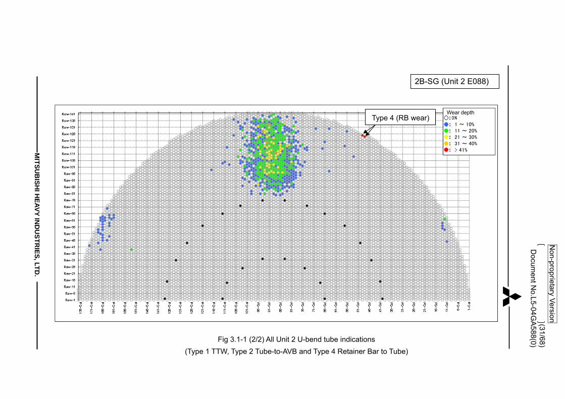
Non-proprietary V
ersion
MIT
SU
BIS
HI H
EA
VY
IND
US
TR
IES
, LTD
.
(31/68)D
ocument N
o.L5-04GA
588(0)
2B-SG (Unit 2 E088)
Fig 3.1-1 (2/2) All Unit 2 U-bend tube indications
(Type 1 TTW, Type 2 Tube-to-AVB and Type 4 Retainer Bar to Tube)
Type 4 (RB wear)1 ~ 10%11 ~ 20%21 ~ 30%31 ~ 40%> 41%
Wear depth
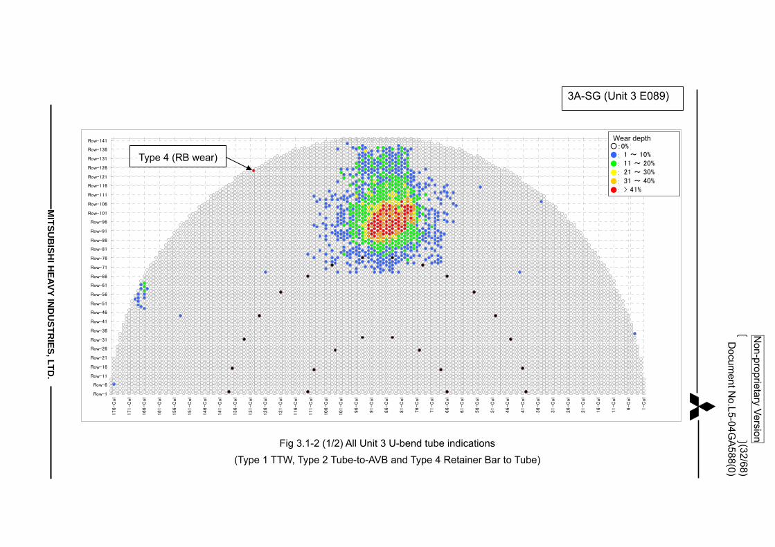
Non-proprietary V
ersion
MIT
SU
BIS
HI H
EA
VY
IND
US
TR
IES
, LTD
.
(32/68)D
ocument N
o.L5-04GA
588(0)
3A-SG (Unit 3 E089)
Row-1
Row-6
Row-11
Row-16
Row-21
Row-26
Row-31
Row-36
Row-41
Row-46
Row-51
Row-56
Row-61
Row-66
Row-71
Row-76
Row-81
Row-86
Row-91
Row-96
Row-101
Row-106
Row-111
Row-116
Row-121
Row-126
Row-131
Row-136
Row-141
1-C
ol
6-C
ol
11-C
ol
16-C
ol
21-C
ol
26-C
ol
31-C
ol
36-C
ol
41-C
ol
46-C
ol
51-C
ol
56-C
ol
61-C
ol
66-C
ol
71-C
ol
76-C
ol
81-C
ol
86-C
ol
91-C
ol
96-C
ol
101-C
ol
106-C
ol
111-C
ol
116-C
ol
121-C
ol
126-C
ol
131-C
ol
136-C
ol
141-C
ol
146-C
ol
151-C
ol
156-C
ol
161-C
ol
166-C
ol
171-C
ol
176-C
ol
LEGEND○:0%●:AVB 1 ~ 10%●:AVB 11 ~ 20%●:AVB 21 ~ 30%●:AVB 31 ~ 40%●:AVB > 41%
Fig 3.1-2 (1/2) All Unit 3 U-bend tube indications
(Type 1 TTW, Type 2 Tube-to-AVB and Type 4 Retainer Bar to Tube)
Type 4 (RB wear) 1 ~ 10%11 ~ 20%21 ~ 30%31 ~ 40%> 41%
Wear depth
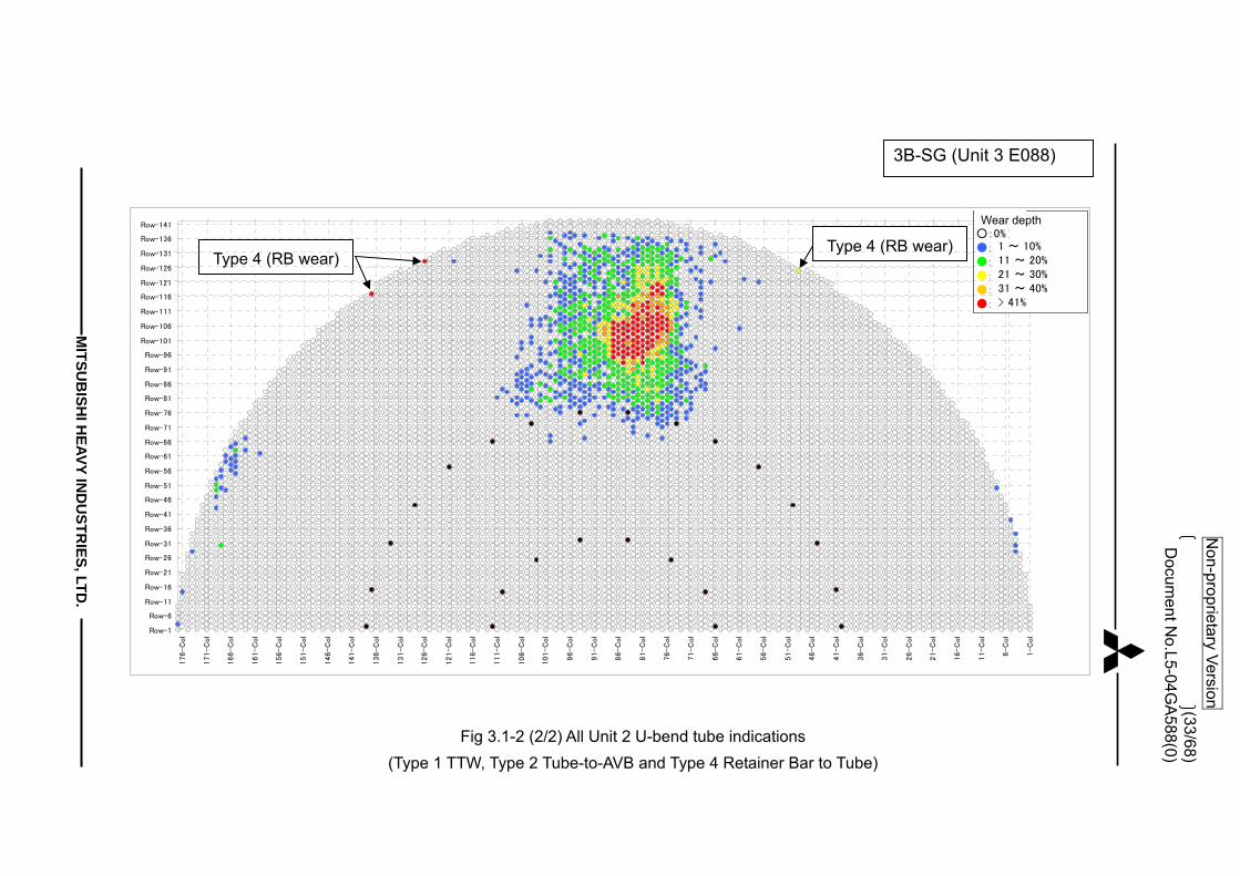
Non-proprietary V
ersion
MIT
SU
BIS
HI H
EA
VY
IND
US
TR
IES
, LTD
.
(33/68)D
ocument N
o.L5-04GA
588(0)
3B-SG (Unit 3 E088)
Row-1
Row-6
Row-11
Row-16
Row-21
Row-26
Row-31
Row-36
Row-41
Row-46
Row-51
Row-56
Row-61
Row-66
Row-71
Row-76
Row-81
Row-86
Row-91
Row-96
Row-101
Row-106
Row-111
Row-116
Row-121
Row-126
Row-131
Row-136
Row-141
1-C
ol
6-C
ol
11-C
ol
16-C
ol
21-C
ol
26-C
ol
31-C
ol
36-C
ol
41-C
ol
46-C
ol
51-C
ol
56-C
ol
61-C
ol
66-C
ol
71-C
ol
76-C
ol
81-C
ol
86-C
ol
91-C
ol
96-C
ol
101-C
ol
106-C
ol
111-C
ol
116-C
ol
121-C
ol
126-C
ol
131-C
ol
136-C
ol
141-C
ol
146-C
ol
151-C
ol
156-C
ol
161-C
ol
166-C
ol
171-C
ol
176-C
ol
LEGEND○:0%●:AVB 1 ~ 10%●:AVB 11 ~ 20%●:AVB 21 ~ 30%●:AVB 31 ~ 40%●:AVB > 41%
Fig 3.1-2 (2/2) All Unit 2 U-bend tube indications
(Type 1 TTW, Type 2 Tube-to-AVB and Type 4 Retainer Bar to Tube)
Type 4 (RB wear) Type 4 (RB wear) 1 ~ 10%
11 ~ 20%21 ~ 30%31 ~ 40%> 41%
Wear depth

(34/68) Document No.L5-04GA588(0)
MITSUBISHI HEAVY INDUSTRIES, LTD.
Non-proprietary Version
3.2 Tube-to-AVB Wear Experience in Other Large CE-Plant RSGs
Tube wear patterns similar to those observed at SONGS were reported at the Plant-A large U-bend steam generators that were replacements for CE manufactured OSGs (See NRC ADAMS ML11270A015 and ML093230226). The Plant-A steam generators were designed by another vendor. They are slightly smaller than the SONGS steam generators but have U-bend tubes, flat bar AVBs, and BEC type TSPs, that are similar to the SONGS RSGs, except SONGS features a 12 AVB design and Plant-A has an 8 AVB design.
(a) SONGS (12AVB design) (b) Plant-A (8 AVB design) Fig.3.2.1-1 Comparison between 12 and 8 AVB Design
The Plant-A inspection results show a wear pattern with many tubes in the center of the U-bend that have tube-to-AVB wear similar to that found in the SONGS steam generators. Figure 3.2.1-2 shows the tubes with tube-to-AVB wear identified at Plant-A during the first inspection following installation of the RSGs and Figure 3.2.1-3 shows the tubes with tube-to-AVB wear identified at Plant-A during the second cycle inspection. Note that the locations of the Plant-A indications are very similar to those for SONGS shown in Figs. 3.1-1 and 3.1-2. Figure 3.2.1-4 compares the total number of tube-to-AVB wear indications for Plant-A, SONGS Unit 2, and SONGS Unit 3 as a function of time and Figure 3.2.1-5 shows the average wear depths for the three plants (six RSGs) as a function of time. As can be seen from these figures, the total number of indications and average wear depth at Plant-A are comparable to that at SONGS. Figure 3.2.1-5 suggests that the tube-to-AVB wear depths at Plant-A have reached a plateau. The reason for such a plateau is unclear. It may be indicative of the type of tube vibration mechanism or an effect of the support condition. But it is clear that the number of tubes with tube-to-AVB wear at Plant-A is growing (refer to Fig. 3.2.1-2 and 3.2.1-3).
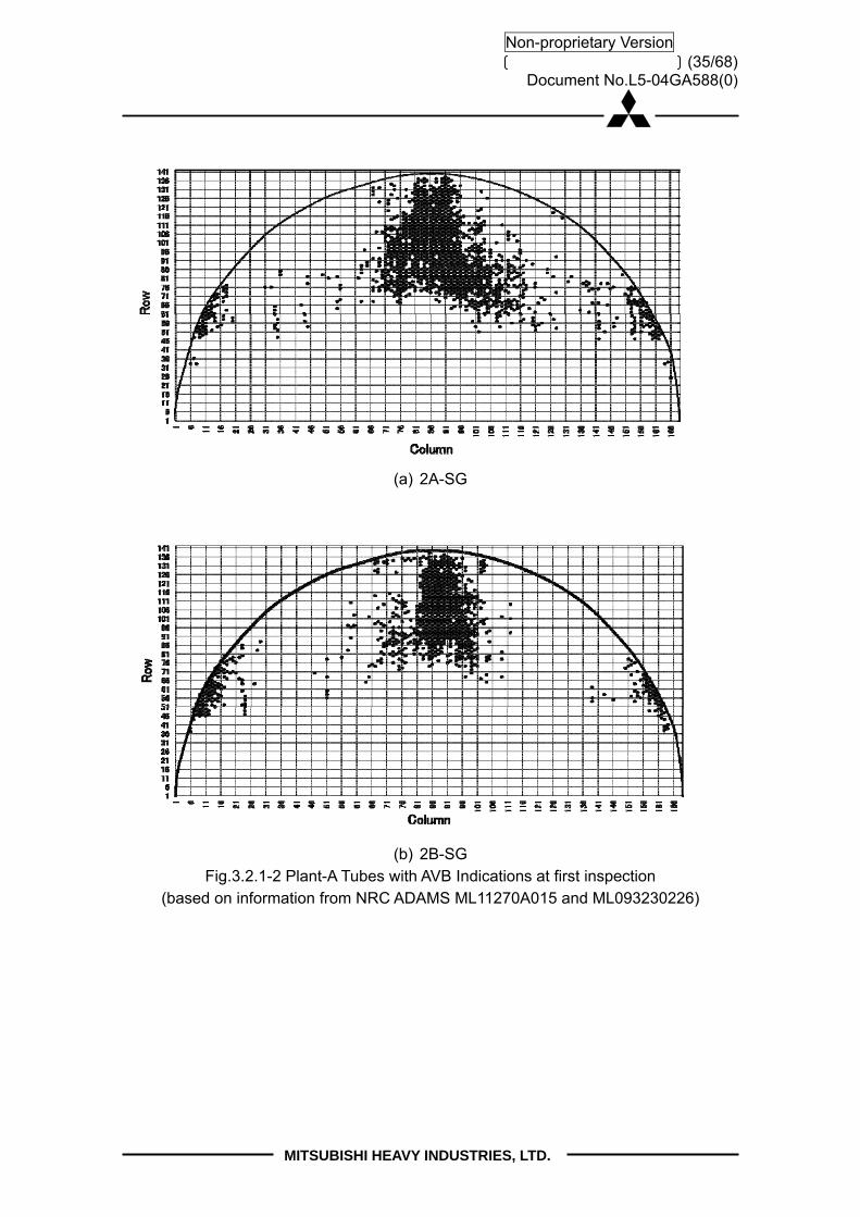
(35/68) Document No.L5-04GA588(0)
MITSUBISHI HEAVY INDUSTRIES, LTD.
Non-proprietary Version
(a) 2A-SG
(b) 2B-SG
Fig.3.2.1-2 Plant-A Tubes with AVB Indications at first inspection (based on information from NRC ADAMS ML11270A015 and ML093230226)

(36/68) Document No.L5-04GA588(0)
MITSUBISHI HEAVY INDUSTRIES, LTD.
Non-proprietary Version
(a) 2A-SG
(b) 2B-SG
Fig.3.2.1-3 Plant-A Tubes with AVB Indications at second inspection
(based on information from NRC ADAMS ML11270A015 and ML093230226)

(37/68) Document No.L5-04GA588(0)
MITSUBISHI HEAVY INDUSTRIES, LTD.
Non-proprietary Version
b
Fig.3.2.1-4 Total Tube-to-AVB Wear Indications (based on information from NRC ADAMS ML11270A015 and ML093230226)
Fig.3.2.1-5 Average Tube-to-AVB Wear Rate (based on information from NRC ADAMS ML11270A015 and ML093230226)
Plant-A #A
Plant-A #B
Plant-A #A
Plant-A #B

(38/68) Document No.L5-04GA588(0)
MITSUBISHI HEAVY INDUSTRIES, LTD.
Non-proprietary Version
3.3 Causes of Type 2 Tube Wear (Tube-to-AVB wear) The cause of the Type 2 wear is turbulence induced (random) tube vibration. The following discussion explains the basis for this conclusion. Fig. 3.3-1 (this figure is similar to Fig. 6.2-1 in the TER (Ref. 1)) provides a summary of the basis for establishing the cause of the Type-2 (tube-to-AVB) wear. Extensive inspections, including visual, eddy current, and ultrasonic methods, indicate that the tube-to-AVB gaps are small at each of the wear sites. This indicates that there are small clearances. Such conditions are sufficient to prevent out-of-plane FEI but not sufficient to prevent turbulence induced (random) vibration and wear. The Type-2 wear indications are in the region of high void fraction and dynamic pressure. Referring to Fig. 2.3.4-3 of the previous section, it can be seen that the area of the U-bend occupied by the high average void fraction (values above where the max value is ) is very similar to the Type-2 wear map in Figs. 3.1-1 and 3.1-2. As shown in the figure at the upper left corner of Fig.3.3-2, insufficient contact force has an adverse effect on tube wear caused by random tube vibration up to the point where the contact force is sufficient to prevent tube lift-off from (or sliding along) the AVB. The amount of contact force necessary to prevent random vibration is a function of the thermal-hydraulic condition. As the void fraction (steam quality) increases, the amount of contact force necessary to prevent random vibration increases. This is because the higher void fraction (steam quality) results in lower external fluid damping and a reduction in the liquid film damping (squeeze film damping). A comparison of Fig. 2.3.4-3 showing the average void fraction and the figures on the bottom of Fig. 2.3.3-3 showing Unit 2 and Unit 3 contact forces indicates that the tubes in the area of average high void fraction also generally have low contact forces, which generally correspond as well to the Type 2 wear maps in Figs. 3.1-1 and 3.1-2. The turbulence induced (random) tube vibration associated with the small gaps and small contact forces combined with the lower tube damping in the high void fraction regions is sufficient to produce the observed wear.

(39/68) Document No.L5-04GA588(0)
MITSUBISHI HEAVY INDUSTRIES, LTD.
Non-proprietary Version
Fig.3.3-1 Type 2 Wear (AVB wear) Mechanism
Visual, ECT and UT Inspections - Small gaps confirmed; eliminates out-of-plane FEI - Wear is local, no in-plane vibration evidence
In an area of high turbulence - Small gaps confirmed - Low contact force

(40/68) Document No.L5-04GA588(0)
MITSUBISHI HEAVY INDUSTRIES, LTD.
Non-proprietary Version
Fig.3.3-2 Contact force sufficient to prevent random tube vibration
Contact force
Wea
r de
pth
rate
Low Void Fraction
High Void Fraction
Required Contact Force toprevent tube random vibration

(41/68) Document No.L5-04GA588(0)
MITSUBISHI HEAVY INDUSTRIES, LTD.
Non-proprietary Version
3.3.1 Evaluation of U-bend Support Conditions
The SONGS SG tube bundles were conservatively designed for U-bend support with effective “zero” gaps in the hot condition and featured 12 AVBs to provide additional support margin. Based on visual inspections and ECT gap measurements, no significant gaps between the tubes and AVBs are present leading to the conclusion that the tubes were well supported. Despite the gap control and additional support provided by the 12 AVB design, an unexpected amount of Type 2 wear was been experienced in the SONGS RSGs. While the number of tubes with Type 2 wear is very similar for Unit 2 and Unit 3 (Compare Table 1-1 and Table 1-2), Unit 2 has operated approximately twice as long as Unit 3. As a result, as shown in Fig. 3.2.1-5. the wear rate in Unit 3 is faster than that for Unit 2. An explanation for this difference is found in the manufacturing assessment which concluded that the tube to AVB contact forces in Unit 3 were less than half than those in Unit 2. (See Section 2.3.3 above.) The increased Unit 3 tube wear is attributable to a different contact force distribution between the tubes and AVBs. When the contact force is sufficiently high to prevent random tube vibration, the tube-to-AVB wear becomes negligible. The magnitude of the contact force that prevents random tube vibration is a function of the void fraction, with a higher contact force being needed in the regions of higher void fraction (steam quality).
(42/68) Document No.L5-04GA588(0)
MITSUBISHI HEAVY INDUSTRIES, LTD.
Non-proprietary Version
3.3.2 Secondary Side Thermal Hydraulic Conditions
Figure 3.3.2-1 (this Fig. displays the same data as Fig. 5.1-4 in the TER (Ref. 1)) shows a strong correlation between void fraction (steam quality) and the percentage of tubes at different levels of void fraction and steam quality that have Type 2 wear. Of the 38,908 tubes in the Unit 2 and 3 RSGs, 2,848 tubes had Type 2 wear and of those tubes 2,702 fall within the region of a maximum steam quality equal to or greater than and a void faction equal to or greater than . In addition, the tubes with Type 2 wear indications typically have high cross flow velocity as shown in Fig. 3.3.2-2 (this Fig. displays the same data as Fig. 5.1-5 in the TER (Ref. 1)). Consequently, it is concluded that the thermal-hydraulic conditions in the SG secondary side, particularly the high void fraction (steam quality) and high flow velocity, are associated with the Type 2 wear. The amount of contact force necessary to prevent random vibration is a function of the thermal-hydraulic condition. As the void fraction (steam quality) increases, the amount of contact force necessary to prevent random vibration increases. This is because the higher void fraction (steam quality) results in lower external fluid damping and a reduction in the liquid film damping (squeeze film damping). Thus, tubes in the region of highest void fraction are most susceptible to this mechanism. This correlation to high void fraction area is also supported by the tube-to-AVB wear observed at the Plant A RSGs. As with the SONGS RSGs, the great majority of the tube-to-AVB wear occurred in the center column region where the void fraction is high.

(43/68) Document No.L5-04GA588(0)
MITSUBISHI HEAVY INDUSTRIES, LTD.
Non-proprietary Version
Fig.3.3.2-1 Correlation between Type 2 Wear (AVB wear) and Void Fraction (Steam Quality)
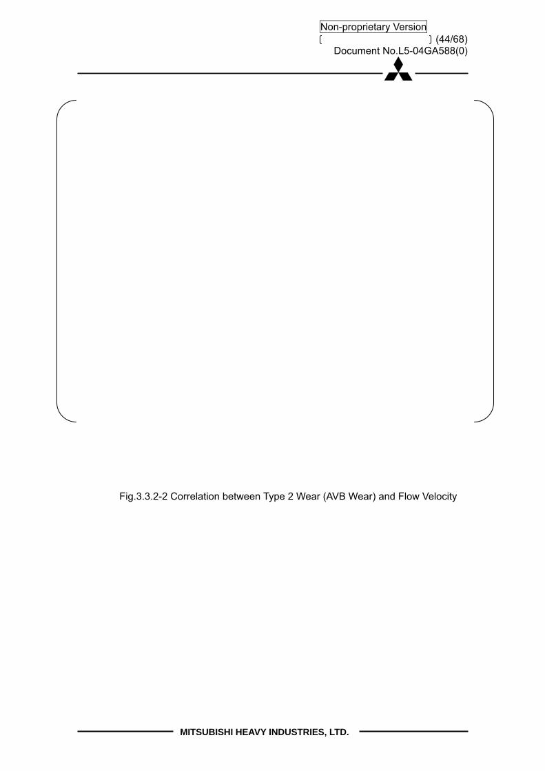
(44/68) Document No.L5-04GA588(0)
MITSUBISHI HEAVY INDUSTRIES, LTD.
Non-proprietary Version
Fig.3.3.2-2 Correlation between Type 2 Wear (AVB Wear) and Flow Velocity
(45/68) Document No.L5-04GA588(0)
MITSUBISHI HEAVY INDUSTRIES, LTD.
Non-proprietary Version
3.4 Out-of-plane FEI is not the cause of AVB wear MHI evaluated the potential for out-of-plane FEI to cause Type 2 wear and has concluded for three reasons that out-of-plane FEI did not occur. First, gap measurements were made in Unit 2 and Unit 3 RSGs. These included ultrasonic gap measurements and over 117,000 eddy current gap measurements (See AREVA Operating Assessment (Ref. 4)). The gap measurements show no excessive gaps between the tubes and AVBs. For most tubes the average of the 24 tube to AVB gap measurements is less than 0.003”. Visual inspections of the AVB and tube intersections (see TER Section 4.2 and Appendix 7 (Ref. 1) also revealed that (i) the gaps between the tubes and AVBs are small without any large gaps, (ii) the AVBs appeared to be straight without detectable abnormalities, (iii) there were no abnormalities in the orientation between the AVBs and the tubes, and (iv) there were no abnormalities in the AVB positions or end cap to retaining bar welds. Second, research literature shows that gaps significantly larger than the SONGS RSG AVB-to-tube gaps are required for out-of-plane FEI to occur. Based on the research report by Weaver (Ref. 6), no out-of-plane FEI in the U-bend tube bundle with AVBs occurred when the symmetric tube-to-AVB gaps were 0.3 mm (12 mils), while out-of-plane FEI occurred when the symmetric gaps were 0.51 mm (20 mils). From the research by Yang (Ref. 7), no out-of-plane FEI occurs even when the tube-to-AVB gap was 1.5 mm (60 mils). These research results indicate that out-of-plane FEI will not occur when the gaps on each side of the tube are smaller than 20 mils. Third, MHI has performed wear calculations using IVHET assuming random vibration force to reproduce the observed wear at SONGS (see TER, Appendix 10 (Ref. 1), Section 7.2). The wear simulations assumed that some of the supports were active (in contact with the AVB by sufficient contact force) and that other supports were inactive, some with very small tube-to-support clearances and some with very small (or zero) contact forces. In the latter (inactive) support condition, the tube can interact with the support (i.e. repeatedly impacting it) and cause turbulence induced (random) wear. In the analysis, the inactive supports were assumed to have symmetric gaps between the tube and AVB. Many wear depth simulations were evaluated by varying the number of inactive supports. The calculated wear depths assuming random vibration are consistent with the actual measurement results of tube wear. Fig. 3.4-1 shows the results for a single tube-to-AVB intersection with large wear assuming different numbers of inactive supports with impact. This figure shows that assuming 8 consecutive AVB support points are inactive (but with impact), the calculated random wear depth is similar to the observed wear (see Fig. 3.4-1). These wear simulations show that with the small clearances at the inactive
(46/68) Document No.L5-04GA588(0)
MITSUBISHI HEAVY INDUSTRIES, LTD.
Non-proprietary Version
supports, random vibration is sufficient to reproduce the observed wear.
Fig.3.4-1 Wear Analysis Results for Type 2 AVB Wear at Tube R106 C78 of Unit 2A SG (2E089)

(47/68) Document No.L5-04GA588(0)
MITSUBISHI HEAVY INDUSTRIES, LTD.
Non-proprietary Version
3.5 Relationship between Random Vibration and In-plane FEI MHI has analyzed whether random vibration was a precursor to the in-plane FEI that was observed in Unit 3. Two possible scenarios were considered.
Scenario #1: In-plane FEI in Unit 3 had no precursor Scenario #2: Wear from random vibration progresses to the point of loss of in-plane support, followed by the onset of in-plane FEI
The first scenario is more likely supported based on the investigation below (See Fig.3.5-1 and Fig.3.5-2): 1) While the number of tubes with tube-to-AVB wear without in-plane TTW is greatest
at the top of the tube bundle, the number of TTW tubes with tube-to-AVB wear is almost uniformly distributed along the different AVB intersections. (See Fig. 3.5-1.) If random vibration wear were a precursor for in-plane FEI TTW, then the pattern of AVB wear for TTW tubes should resemble the tube-to-AVB wear pattern (i.e. be concentrated at the top of the tube bundle). However, this is not observed for tubes with TTW.
2) While the tube-to-AVB wear depth for tubes without in-plane TTW is greatest at the top of the tube bundle, the tube-to-AVB wear depths for tubes with in-plane TTW is almost uniformly distributed along the AVB intersections. (See Fig. 3.5-2.) If random vibration wear were a precursor for in-plane FEI wear, then the AVB wear for the tubes with in-plane FEI would be greatest at the top of the U-bends. But for TTW tubes, the average wear depth is almost the same in all AVB support locations and there is no tendency to concentrate at the top of the tube bundle.
3) The average 10% of AVB wear depth in Unit 2 and Unit 3 excluding TTW tubes is almost the same. (See Fig. 3.5-2.) Therefore, if random vibration were a precursor to in-plane FEI one would expect to see a similar number of tubes with tube-to-tube wear in the two RSG units. However, Unit 2 only has 2 tubes with TTW.

(48/68) Document No.L5-04GA588(0)
MITSUBISHI HEAVY INDUSTRIES, LTD.
Non-proprietary Version
B01 B02 B03 B04 B05 B06 B07 B08 B09 B10 B11 B12
2A TTW 0 0 0 0 2 2 2 1 0 1 0 0
2B TTW 0 0 0 0 0 0 0 0 0 0 0 0
3A TTW 119 127 133 153 151 147 135 146 132 95 69 87
3B TTW 105 125 129 135 133 122 120 133 139 129 123 115
0
50
100
150
200
箇所
数合
計値
TTW管 AVB部での減肉箇所数
B01 B02 B03 B04 B05 B06 B07 B08 B09 B10 B11 B12
2A AVB 5 11 85 185 362 520 544 497 273 85 14 2
2B AVB 1 3 40 127 266 333 361 324 191 102 8 2
3A AVB 5 13 77 222 301 380 346 265 169 57 10 3
3B AVB 3 25 137 222 312 408 369 252 167 132 16 3
0
100
200
300
400
500
600
箇所
数合
計値
AVB管 AVB部での減肉箇所数(TTW管を除く)
B07 B08
B09
B11
B05B06
B03
B02
B01
B10
B1207C07H
B04
Figure 3.5-1 AVB Tube Wear Number Comparison
Number of TTW Tube with AVB wear
Number of Tube to AVB Wear Tubes (excluding TTW tubes)
No.
of A
VB
Wea
r N
o. o
f AV
B W
ear
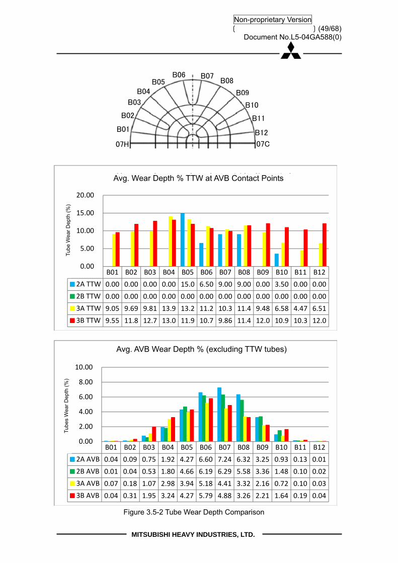
(49/68) Document No.L5-04GA588(0)
MITSUBISHI HEAVY INDUSTRIES, LTD.
Non-proprietary Version
B01 B02 B03 B04 B05 B06 B07 B08 B09 B10 B11 B12
2A TTW 0.00 0.00 0.00 0.00 15.0 6.50 9.00 9.00 0.00 3.50 0.00 0.00
2B TTW 0.00 0.00 0.00 0.00 0.00 0.00 0.00 0.00 0.00 0.00 0.00 0.00
3A TTW 9.05 9.69 9.81 13.9 13.2 11.2 10.3 11.4 9.48 6.58 4.47 6.51
3B TTW 9.55 11.8 12.7 13.0 11.9 10.7 9.86 11.4 12.0 10.9 10.3 12.0
0.00
5.00
10.00
15.00
20.00
減肉
合計
値/箇
所数
合計
値
TTW管 AVB部での減肉率合計値/指示本数
B01 B02 B03 B04 B05 B06 B07 B08 B09 B10 B11 B12
2A AVB 0.04 0.09 0.75 1.92 4.27 6.60 7.24 6.32 3.25 0.93 0.13 0.01
2B AVB 0.01 0.04 0.53 1.80 4.66 6.19 6.29 5.58 3.36 1.48 0.10 0.02
3A AVB 0.07 0.18 1.07 2.98 3.94 5.18 4.41 3.32 2.16 0.72 0.10 0.03
3B AVB 0.04 0.31 1.95 3.24 4.27 5.79 4.88 3.26 2.21 1.64 0.19 0.04
0.00
2.00
4.00
6.00
8.00
10.00
減肉
合計
値/箇
所数
合計
値
AVB管 AVB部での減肉率合計値/指示本数(TTW管を除く)
Figure 3.5-2 Tube Wear Depth Comparison
Avg. Wear Depth % TTW at AVB Contact Points
Avg. AVB Wear Depth % (excluding TTW tubes)
Tub
e W
ear
Dep
th (
%)
Tub
es W
ear
Dep
th (
%)
B07 B08
B09
B11
B05B06
B03
B02
B01
B10
B12
07C07H
B04
(50/68) Document No.L5-04GA588(0)
MITSUBISHI HEAVY INDUSTRIES, LTD.
Non-proprietary Version
3.6 Conclusion
MHI concludes that under the secondary thermal-hydraulic conditions such as in the SONGS SGs, certain tube-to-AVB minimum contact force is required to prevent tubes from vibrating and eventually causing wear at AVB intersections. According to the manufacturing dimensional tolerance analysis, the average contact force in the Unit 3 SGs was found to be smaller than the average contact force in the Unit 2 SGs, as shown in Fig. 2.3.3-3. Therefore, it is concluded that the contact forces of Unit 3 were more likely to be insufficient to prevent turbulence induced (random) vibration of tubes and the Unit 3 SGs were more susceptible to turbulence induced (random) vibration, as shown in Figs. 3.2.1-4 and 3.2.1-5.

(51/68) Document No.L5-04GA588(0)
MITSUBISHI HEAVY INDUSTRIES, LTD.
Non-proprietary Version
4. Design Approach
4.1 Design Approach (circa 2005-06) 4.1.1 General Design and Performance Requirements In September 2004, MHI was awarded a contract to replace SCE’s OSGs at SONGS Units 2 and 3. The general design requirements, performance requirements, and design criteria for the SONGS RSGs were set forth in SCE’s “Certified Design Specification (CDS), SO23-617-01 (Ref. 8)”. Significant features of the CDS were the intended use of the provisions of 10 C.F.R. §50.59 to minimize the impact of the RSGs on the existing plant licensing basis (CDS 3.6.1) and the requirement to closely match the dimensions and function of the OSGs (CDS 3.9.1). These features meant that the RSGs needed to “be as close as possible to the existing steam generators in form, fit, and function” (CDS 3.6.1.1).
While the overall RSG had to fit within the size, weight, and volume limits related to those of the OSG, the tube bundle heat transfer area was to be maximized (CDS 3.8.1.1).
The CDS specified Alloy 690TT tube material (CDS 3.9.3.8), which has a thermal conductivity that is approximately 10% less than that of the OSG tube material. In addition, the number of tubes had to be increased by 8% to accommodate future tube plugging (CDS 3.9.1). These factors led to the increase of the tube bundle heat transfer surface area from 105,000ft2 (OSG) to 116,100 ft2 (an 11% increase), an increase in the number of tubes from 9,350 (OSG) to 9,727 (RSG), and to the RSG tube bundle being taller than that of the OSG. 4.1.2 U-bend Design Approach for Vibration Control
Minimizing tube wear resulting from vibration was a high priority in the design of the SONGS RSGs. The design approach used to prevent flow induced tube vibration has two main elements. The first is to establish the required distance between tube supports (the tube span) and the second is to establish the minimum practical tube-to-support clearance. In general these design elements have been established and proven in earlier operating SGs. Tube Span: The purpose of supporting a tube at multiple locations along its length is to increase the tube natural frequency. The design basis for such spacing is that the first mode of the supported tube be greater than the anticipated forcing frequency. In U-tube steam generators with ¾” diameter tubes, the typical span in the straight legs is –
. A shorter span is typically applied to the arc length of the U-tube with the largest

(52/68) Document No.L5-04GA588(0)
MITSUBISHI HEAVY INDUSTRIES, LTD.
Non-proprietary Version
bend radius. In the case of the SONGS RSGs, the straight leg tube support span is and the maximum U-bend span is less than half that of the straight leg spans (< everywhere). Tube-to-Support Clearance: The reason for maintaining clearance between the tube and its supports (both tube support plates and AVBs) is to permit the tube to move freely in the axial direction, while restraining it in the lateral direction. Freedom to move in the axial direction is needed to assemble the tube bundle and also allows the tubes to expand due to increased temperature and pressure during operation without binding. The general goal is to design and assemble the tube bundle with the smallest possible clearances between the tubes and the supports without imposing compressive forces on the tubes. In tube support plates the minimum clearance is typically between and . For U-bend supports (AVBs) the clearance is typically controlled to an average gap of 0.005” with allowances for larger gaps on the bundle sides. The effect of decreasing the tube-to-support clearance is to increase the probability that the tube is contacting the support (on one side), which is believed to provide the best fully supported condition. Small clearances also tend to dampen vibratory tube displacements when they happen. The SONGS tube-to-AVB clearances were controlled to a nominal of 0.002" in the cold condition, with a smaller dimensional variation than that achieved by MHI on prior SGs. The gap variations in Unit 3 were smaller than those of Unit 2, reflecting the improvement in precision gained during the manufacturing process. At the time of the SONGS RSG design, these were the design elements used to prevent tube vibration. The AVB tube support concept had been validated by multiple experiments and by years of operating SG experience. It was based on the evidence that placing AVBs between tube columns to prevent out-of-plane tube vibration also prevented tube vibration in the in-plane direction. As stated above, the design choices available to the designer and fabricator are limited to tube span and tube-to-support clearance. The flow conditions are largely a function of the plant power level, operating conditions, and SG size limitations. The Role of Analysis: A variety of analyses are performed during the design process to estimate the tube vibration and wear characteristics of the design. These analyses include a performance calculation that determines the flow resistances throughout the SG recirculation path (downcomer, bundle, primary moisture separators, recirculating pool) and calculates the circulation ratio. Then there is a 3D tube bundle thermal / hydraulic analysis that uses the circulation ratio as a boundary condition. This is the code that produces fluid velocities and densities throughout the tube bundle. Such

(53/68) Document No.L5-04GA588(0)
MITSUBISHI HEAVY INDUSTRIES, LTD.
Non-proprietary Version
codes are typically “single fluid” codes and are not capable of modeling the trajectories of water and steam separately. So, they are rough approximations of the actual flow behavior. Next are the post-processors that organize the output from the flow model. Sometimes at this stage flow multipliers are added to account for geometric features not modeled (for instance, sometimes the flow peaking effects of the AVBs is added at this stage). Next is a vibration analysis program that uses the output from the flow analysis post processor and the assumed tube support conditions to calculate tube response. This program is used to analyze each of the various U-tube geometries that are found within the U-bend. This analysis calculates tube displacements at the supports for fluid elastic vibration, turbulence excitation, and vortex shedding. Generally, in the U-bend the dominant mechanism is fluid elastic vibration with turbulent excitation providing a smaller contribution. Vortex shedding is not applicable in the two-phase U-bend region. All analysis is directed toward the tube out-of-plane response. Once the tube motions are established, a wear analysis program is used to determine material loss over time. This calculation needs the inputs of tube travel distance and tube-to-support contact (normal) force, plus a wear coefficient to determine wear volume, which is converted to tube wall wear depth. The normal forces (and motions) come from the out-of-plane response to fluid elastic forces. The sliding distance in the in-plane direction comes from the cross flow turbulence forces. Gap elements in the tube model quantify the normal force time history and sliding time history at the tube support points. The tube-to-support wear coefficient is a function of temperature, pressure, water chemistry, steam-to-water ratio, material form, surface hardness, and is taken from prototypic tests of materials in SG environments. This calculation considers both impact wear and sliding wear. A central premise of the analysis is that tube wear and impact forces are proportional to the size of the tube-to-AVB gap. Therefore, minimization of tube wear is the natural result of minimizing the tube-to-support clearances. The suite of codes used by each vendor to perform tube wear calculations are developed as a set and are generally calibrated against experimental data or field experience so that together they produce results that are reasonably similar to what has been observed in operating SGs and experiments. However, they are only an approximation, so conservatisms are often included throughout the process. SCE / MHI AVB Design Team: In mid-2005 a joint SCE / MHI AVB Design Team was formed for the purpose of minimizing the potential for tube vibration and wear in the SONGS RSGs. For the first six months, video meetings were scheduled every two weeks and technical or design review meetings were held on a two month cycle. The AVB Design Team generated

(54/68) Document No.L5-04GA588(0)
MITSUBISHI HEAVY INDUSTRIES, LTD.
Non-proprietary Version
many action items and answered many questions, several of which dealt with high void fraction and how to minimize it. This process continued through the end of 2006. The AVB team investigated instances of U-bend tube degradation using the INPO, NPE (Nuclear Power Experience), and NRC databases and studied whatever could be found describing the design of other similarly large SGs. The SONGS RSG design was compared to the design for another large RSG that was operating at another CE-type plant. The RSGs for the comparison plant had reported 22 tubes with U-bend wear after the third operating cycle (July 2005). The end product was a design for the SONGS RSGs with more AVB supports and shorter spans in the U-bend region than the comparison plant, along with effective zero tube-to-AVB gaps during operation. The resulting tube vibration potential was judged to be ~70% that of the comparison plant. The tube bundle design specifically focused on preventing out-of-plane tube vibration. Industry practice and experience dictated that controlling out-of-plane vibration would preclude in-plane vibration. Reflecting this industry practice, the Japan Society of Mechanical Engineers’ “Guideline for Fluid-elastic Vibration Evaluation of U-bend Tubes in Steam Generators” (Ref. 9) states that in-plane vibration does not need to be considered if out-of-plane vibration is controlled. (See Appendix 1.) An important experiment studying FEI in U-bends (Ref. 6) by Weaver and Schneider states that “The effect of flat bar supports with small clearance is to act as apparent nodal points for flow-induced tube response. They not only prevented the out-of-plane mode as expected but also the in-plane modes. No in-plane instabilities were observed, even when the flow velocity was increased to three times that expected to cause instability in the apparently unsupported first in-plane mode”. Weaver and Schneider also increased the clearances between flat bar supports and U-tubes, but were not able to produce in-plane instability. The NRC, in its Augmented Inspection Team (AIT) report (Ref. 12), recognized this existing industry practice, noting that
Traditional design of anti-vibration bar systems have not considered in-plane fluid forces since it was accepted that the rigidity and dampening strength of the tube in this direction preclude it. This event at SONGS is the first US operating fleet experience of in-plane fluid-elastic stability, sufficient to cause tube-to-tube contact and wear in the U-bend region.“ AIT at page 49.

(55/68) Document No.L5-04GA588(0)
MITSUBISHI HEAVY INDUSTRIES, LTD.
Non-proprietary Version
In February 2005 a paper was published (Ref. 10) that described an experiment of a small U-bend with a single flat bar support at the apex of the U-tubes. It reports that the experimenters were able to generate both out-of-plane FEI and in-plane FEI. However, U-tube FEI in the in-plane direction has never been observed in the U-tube SGs before its occurrence in the SONGS SGs. The textbook by M. K. Au-Yang (Ref. 11), states that “In-plane modes have never been observed to be unstable even though the computed fluid-elastic stability margins are well below 1” (the fluid-elastic stability margin, FSM, is the inverse of the stability ratio). The AVB Design Team included an independent U-bend tube vibration expert who explained that rapid tube wear is driven more by fluid elastic vibration than by turbulence, so the effectiveness of the tube supports is very important. In the analytical evaluation, considering the possibility of missing supports is a way of assuring the design has margin against fluid elastic vibration. This is the reason that the MHI vibration analysis included an evaluation of inactive (missing) supports to demonstrate margin against FEI. Tube and AVB Fabrication and U-bend Assembly During the fabrication and assembly of the SONGS RSGs, many steps were taken to achieve the essentially effective zero gap, parallelism and uniformity of the U-bend assembly specified by the CDS2 and believed to be critical based on existing industry practice and experience to minimize tube vibration. Reducing the tube-to-AVB gaps has the potential to increase the contact force and reduce tube damping. Tube mechanical damping, which is present when there are small gaps, is particularly important to inhibit FEI when the void fraction is high and fluid damping is low. The AVB Design Team decided on an AVB gap design basis with the most uniform gaps achievable and as near zero without excessive preload. So the variation of tube-to-AVB gap sizes was minimized to avoid an increase of contact force (preload) by increasing the nominal AVB thickness, reducing the AVB thickness tolerance, reducing the allowable value for twist, and decreasing the tolerance for the tube G-value (diameter). Manufacturing mockups were used to quantify, improve, and qualify the tube-to-retaining bar welding process. Improvements in the manufacturing processes for the SONGS RSGs included the use of metal spacers during retaining bar welding, changing of SG orientation during welding, reduction of weld size to minimize deformation, measurement of every 10 column pitch, and measurement of outer
2 Revision 3 of the CDS, to which the SONGS RSGs were designed and fabricated, specified
“an effective ‘zero’ tube-to-flat bar gap, gap uniformity and parallelism of the tube bundle in the
out-of-plane direction . . .” CDS 3.10.3.5.

(56/68) Document No.L5-04GA588(0)
MITSUBISHI HEAVY INDUSTRIES, LTD.
Non-proprietary Version
peripheral gaps. Based on experience gained in the fabrication of the Unit 2 RSGs, additional precision was incorporated into the fabrication of the Unit 3 RSGs to more effectively implement the effective zero gap, uniformity and parallelism of the U-bend assembly. (See TER at section 5.2.3 and section 2.3.3 above.) 4.1.3 Evaluation of Design Changes to Reduce Void Fraction In the May 2005 Design Review meeting, MHI presented an RSG performance calculation showing high projected void fraction. It was decided that MHI would perform a parametric analysis to determine how the void fraction could be reduced while maintaining the other design requirements. Over the next five months, MHI evaluated alternative design modifications to increase the RSG circulation ratio (and thereby reduce the maximum void fraction). The design alternatives included a larger downcomer, larger TSP flow area, and removing one TSP. None of these alternatives had a large enough effect on the maximum void fraction to justify such a significant change. However, the net result of the effort was to select the 2V x 3 AVB design from among several competing AVB configurations, which had a smaller pressure loss than the competing concepts, but the reduction in maximum void fraction was negligible. The 2V x 3 AVB design provided significant design margin for minimizing tube vibration. In October 2005 the AVB Design Team agreed that the RSG design was optimized for the SONGS application. At the time of shipment of the SONGS RSGs it was believed that they had greater margin against U-bend tube vibration and wear than other similar SGs. 4.2 U-bend Design Approach (circa 2012) 4.2.1 A New Paradigm The forced outage of Unit 3 and the subsequent discovery of thousands of U-bend tube wear indications in both Unit 2 and Unit 3 after such a short operating period was wholly unexpected. Such an outcome should have been prevented by the conservative design and the precision manufacture. The inspection data revealed two significant, heretofore, unexpected conditions. The first condition was the Unit 3 tubes with in-plane FEI, whose in-plane flow induced displacements were large enough to produce tube-to-tube contact (and wear). As stated, in-plane FEI is a new SG tube degradation phenomenon that prior to SONGS had never

(57/68) Document No.L5-04GA588(0)
MITSUBISHI HEAVY INDUSTRIES, LTD.
Non-proprietary Version
been observed in U-tube steam generators. The second condition was the appearance of thousands of tube-to-AVB wear indications in just one operating cycle. A similar condition had appeared in the replacement SGs for another CE plant (Plant A) subsequent to the design and fabrication of the SONGS RSGs. After the first operating cycle, Plant A had 5,668 wear indications compared to SONGS Unit-2 with 4,341 (a full operating cycle) and SONGS Unit-3 with 3,894 (a partial operating cycle) (see Fig. 3.2.1-4). The tube degradation experienced at both Plant A and SONGS is inconsistent with prior operating SG experience and design expectations. The identification of the unexpected tube degradation led to an extensive evaluation as to the causes the degradation and the questioning of the original design assumptions.. 4.2.2 Assessment of the New Paradigm
Based on the numerous technical reports prepared by MHI and others, summarized in this report, it is clear that in-plane FEI occurred in the Unit-3 RSGs. The primary evidence of in-plane FEI discussed in Section 2 includes the following: 1. The tubes in adjacent rows (same column) have matching wear scars on the
intrados and extrados, which are roughly at the 45o (hot leg side) and 135o (cold leg side) locations. This correlates with the displacement shape of the 1st in-plane vibration mode (mode-1) of the U-tubes.
2. The TTW tubes exhibit deep wear at the top TSP, which confirms that the tubes were experiencing large-amplitude, mode-1 in-plane vibration.
3. There are some “victim” tubes on the periphery of the TTW population that were struck by tubes with in-plane FEI. These tubes can be identified by the absence of top-TSP wear.
Extensive evaluations by MHI indicate that the in-plane FEI was caused by insufficient contact forces between the tubes and the AVBs to restrain movement of the tubes in the in-plane direction under high localized thermal hydraulic conditions. The in-plane vibration associated with the wear observed in the Unit 3 RSGs could only have occurred if essentially all of the AVB supports were inactive in the in-plane direction. The Unit 3 tube-to-AVB contact forces on the TTW tubes that were the result of the precise U-bend assembly process are so low that they do not restrain the tubes in the in-plane direction. Based on the analysis, the lack of sufficient contact force to restrain the in-plane

(58/68) Document No.L5-04GA588(0)
MITSUBISHI HEAVY INDUSTRIES, LTD.
Non-proprietary Version
movement of the tubes is the primary cause of the in-plane FEI tube wear observed at SONGS. The high localized thermal hydraulic conditions of the SONGS RSGs are also an important factor, in that tube-to-tube wear was only observed on tubes in areas of high void fraction (steam quality). However, thermal hydraulics are not the controlling factor. SONGS Unit 2 and Unit 3 have identical thermal hydraulic conditions and virtually all of the TTW tubes were found in Unit 3. The explanation for this difference is that the contact forces in Unit 2 are approximately double those in Unit 3. Also, while the TTW was only found in the high void fraction regions of Unit 3, less than of tubes in the high void fraction region exhibited TTW. Furthermore, analyses using ATHOS instead of FIT-III still indicate the tubes are stable assuming no inactive supports but with lower bound damping.
The numerous technical reports prepared by MHI and others, summarized in this report also evaluated the unexpected tube-to-AVB wear observed in the Unit 2 and Unit 3 RSGs. The evaluation has led to the conclusion that the thousands of premature tube-to-AVB wear indications are caused by the presence of thousands of small tube-to-AVB gaps with insufficient contact force in the presence of high void fraction. The number of Unit 2 indications and their wear rates are less than that of Unit 3. This is consistent with the fact that the Unit 2 RSGs have higher tube-to-AVB contact forces than the Unit 3 RSGs. 4.2.3 Design Implications of the New Paradigm
Study of the recently collected data has led to a re-evaluation of the original design basis for the SONGS RSGs. Several preliminary conclusions have been drawn for developing a design that is resistant to vibration: 1. The “effective zero gap” design concept is effective against “out-of-plane FEI” but for
the AVB supports to be active and provide restraint in the in-plane direction requires sufficient tube-to-AVB contact force to generate friction that inhibits in-plane tube displacement. Therefore, the zero gap assembly definition should have included a requirement for small, uniform contact forces (preloads).
2. The magnitude of the required contact force increases in regions of high void fraction (steam quality). Tubes in the high void fraction (steam quality) region of the tube bundle U-bend are more susceptible to in-plane FEI and random vibration because the higher void fraction (steam quality) reduces the external fluid damping and the liquid film damping (squeeze film damping). Therefore it is important to assure that upper bound thermal hydraulic values (void fraction, steam quality, flow velocities, damping, etc.) are assumed in the analysis of the design.
3. If small, uniform contact forces are incorporated, the design basis no longer needs to assume inactive supports and the number of supports does not need to be

(59/68) Document No.L5-04GA588(0)
MITSUBISHI HEAVY INDUSTRIES, LTD.
Non-proprietary Version
greater than what is needed to prevent out-of-plane FEI (i.e. four sets of AVBs instead of six would be sufficient).
The tube degradation experience also has implications for evaluating the sufficiency of the design to prevent wear from turbulence induced (random) vibration. In the absence of out-of-plane FEI and in-plane FEI, the next most powerful tube vibration mechanism is turbulence induced (random) vibration. Given the small gaps and small contact forces, it is a reasonable conclusion that the turbulent flow conditions are sufficient to produce tube-to-AVB impact wear. However, evaluation of the wear data has led to the conclusion that different assumptions need to be made in evaluating wear from random vibration, at least under the conditions present in the SONGS RSGs. To explain the wear rate observed at SONGS using conventional methods, it is necessary (1) to assume consecutive supports with small clearances and/or small contact forces that permit tube-to-AVB impacting to occur within the gap; (2) to replace the fretting wear coefficients, typically used, with impact wear coefficients that are significantly larger; and (3) to use the random excitation forcing function that is based on recent MHI internal two-phase flow test data (Ref. 14). Sample wear calculations using the impact wear coefficient, plus the assumption that tubes have small gaps and/or contact forces at several consecutive AVB locations match the reported wear rates using a turbulence induced (random) vibration assumption (see Appendix-3 and Section 3.4).

(60/68) Document No.L5-04GA588(0)
MITSUBISHI HEAVY INDUSTRIES, LTD.
Non-proprietary Version
5. References
[1] MHI report, “Tube wear of Unit-3 RSG – Technical Evaluation Report”, L5-04GA564 the latest revision
[2] MHI report, “Retainer Bar Tube Wear Report”, L5-04GA561 the latest revision [3] MHI report, “Screening Criteria for Susceptibility to In-Plane Tube Motion”,
L5-04GA571 the latest revision [4] AREVA report, “SONGS U2C17 Steam Generator Operational Assessment for
Tube-to-Tube Wear”, 51-9187230 [5] MHI report, “Evaluation of Stability Ratio for Return to Service”, L5-04GA567 the
latest revision [6] Journal of Engineering for Power, Vol. 105, pp. 775-781, “The Effect of Flat Bar
Supports on the Crossflow Induced Response of Heat Exchanger U-Tubes”, D. S. Weaver, W. Schneider, October 1983
[7] Transactions of the ASME, Vol.120, pp. 138-142, “Flow-induced wear in steam generator tubes-Prediction versus operational experience”, Au-Yang, M. K, 1998
[8] SCE document, “Certified Design Specification of SONGS Unit 2&3 RSGs”, SO23-617-01 revision 3
[9] JSME, S016-2002, Guideline for Fluid-elastic Vibration Evaluation of U-bend Tube in SG, March 2002
[10] ASME, “Fluidelastic Instability and Work-Rate Measurements of Steam-Generator U-Tubes in Air-Water Cross-Flow”, V.P.Janzen, E.G.Hagberg, M.J.Pettigrew, C.E.Taylor. February 2005
[11] ASME Press, New York,” Flow Induced Vibration in Power and Process Plant Components”, Au-Yang, M. K
[12] NRC Augmented Inspection Team Report, “SAN ONOFRE NUCLEAR GENERATING STATION”, 05000361/2012007 and 05000362/2012007.
[13] EPRI technical report, “Steam Generator Vibration and Wear Prediction”, TR-103202, March 1998
[14] MHI report, “Steam Generator Tube Wear Test Data Set”, WJS17906, March 2011
[15] MHI report, “Experimental Study on Impact/Fretting Wear Evaluation of S/G Tube and Tube-Support”, 2507637A, June 1987

(61/68) Document No.L5-04GA588(0)
MITSUBISHI HEAVY INDUSTRIES, LTD.
Non-proprietary Version
Appendix-1 Definition of “active” support condition for FEI and random vibration
1.1 Understanding of “active support“ at the time of design Based on accepted industry understanding and practice at the time of design an active support condition for “out-of-plane FEI” was considered to be active (meaning that the support prevented tube displacement) for “in-plane FEI” and for “random vibration.” Analytically an active support was achieved by adding a pinned support condition to the tube that prevented tube displacement in the out-of-plane and in-plane directions while allowing the tube to rotate. With active pin support conditions, out-of-plane FEI will occur before in-plane FEI because tube U-bend natural frequency in the out-of-plane direction is lower than that in the in-plane direction. It is reasonable to expect that the active pinned support condition is a valid assumption for both the out-of-plane and in-plane directions, because the resulting contact forces between tubes and AVBs will also produce in-plane tube restraint due to friction. This expectation was supported by the field experience at the time of the design of the SONGS RSGs. At the time of design, MHI investigated the field experience of U-bend tube degradation using the INPO, NRC and NPE databases, and found no tube wear in prior operating U-tube SGs caused by in-plane FEI. Based on this accepted industry understanding, the JSME “Guideline for Fluid-elastic Vibration Evaluation of U-bend Tube in SGs” states that in-plane FEI does not need to be considered if out-of-plane FEI is controlled. The JSME guideline (Ref. 9) shows the following examples of a comparison of tube U-bend natural frequency in the out-of-plane and in-plane direction.

(62/68) Document No.L5-04GA588(0)
MITSUBISHI HEAVY INDUSTRIES, LTD.
Non-proprietary Version
Thus, based on accepted industry understanding and practice at the time of design, the “effective zero gap” design incorporated into the SONGS RSGs was considered to be effective with respect to out-of-plane FEI as well as in-plane FEI and random vibration. 1.2 Post SONGS tube wear understanding of “active support” Based on the investigation and analysis of the tube wear in the SONGS RSGs, MHI has now determined that:
The “effective zero gap” design concept is effective against “out-of-plane FEI” and analytically can be represented by a pinned support that is active in the out-of-plane direction.
The conditions necessary for a pinned support to be active in the in-plane direction requires sufficient tube-to-AVB contact force to generate friction that inhibits in-plane tube displacement
A sufficient level of contact force between tube and AVB is necessary for the support to be active in the in-plane direction. The magnitude of the required contact force increases in regions of high void fraction (steam quality).Tubes in the high void fraction (steam quality) region of the tube bundle U-bend are
Fig. A1-1 Example of evaluation of tube U-bend natural frequency with AVBs

(63/68) Document No.L5-04GA588(0)
MITSUBISHI HEAVY INDUSTRIES, LTD.
Non-proprietary Version
more susceptible to in-plane FEI and random vibration because the higher void fraction (steam quality) results in lower external fluid damping and a reduction in the liquid film damping (squeeze film damping), plus higher fluid velocities. High void fraction is an important (but not controlling) factor in the occurrence of in-plane FEI and impact wear due to turbulence induced (random) vibration.
1.3 Summary The discussion above is summarized in Table A1.3-1.
Table A1.3-1 Active or Inactive as to design concept of “effective zero gap”
At design stage Post SONGS tube wear
Out-of-plane FEI Active Active
In-plane FEI Active (*Note) Inactive (insufficient contact forces)
Random vibration
Active Inactive (small gap and/or small contact forces at AVB intersections)
(*Note) At the time of design an active support condition for “out-of-plane FEI” was also
considered to be active for “in-plane FEI”, based on accepted industry understanding and practice.
(64/68) Document No.L5-04GA588(0)
MITSUBISHI HEAVY INDUSTRIES, LTD.
Non-proprietary Version
Appendix-2 Effect of support conditions on FEI out-of-plane and in-plane Critical Velocity
The critical velocity for FEI (out-of-plane or in-plane) depends on the support condition, namely the number of “active” supports (in both the in-plane and out-of-plane directions). In U-bend SGs, if the number of active supports against out-of-plane FEI is identical to the number of active supports against in-plane FEI, the critical velocity for out-of-plane FEI is always lower than what is required to produce in-plane FEI because the natural frequency of out-of-plane FEI is lower than that of in-plane FEI. Therefore out-of-plane FEI will occur before in-plane FEI. However, based on the investigation and analysis of the tube wear at SONGS, MHI concludes that the meaning of “active” is different with respect to “out-of-plane FEI” and “in-plane FEI” as follows:
Active condition against out-of-plane FEI: Narrow gap that is small enough to produce tube-to-AVB contact and mechanical damping (contact force is not necessary)
Active condition against in-plane FEI: Tube-to-AVB contact force sufficient to produce friction that inhibits in-plane tube displacement is required
Based on the investigation of the tube wear at SONGS, MHI concludes that the number of active supports against out-of-plane FEI is not identical to the number of active supports against in-plane FEI. In the case of the SONGS RSGs, the number of active supports against out-of-plane FEI is considered to be the same as designed because narrow or effective zero gaps are confirmed by ECT measurements and visual inspection at tube-to-AVB intersections along representative tubes with wear. On the other hand, for tubes that exhibited tube-to-tube (Type-1) wear, the number of active supports against in-plane FEI is reduced because the contact force is not sufficient. If the number of active supports that prevent in-plane FEI becomes sufficiently less than the number of supports that prevent out-of-plane FEI, the critical velocity of in-plane FEI becomes lower than that of out-of-plane FEI.

(65/68) Document No.L5-04GA588(0)
MITSUBISHI HEAVY INDUSTRIES, LTD.
Non-proprietary Version
Fig. A2-1 Correlation between Number of inactive supports and Critical velocity

(66/68) Document No.L5-04GA588(0)
MITSUBISHI HEAVY INDUSTRIES, LTD.
Non-proprietary Version
Appendix-3 Tube Wear Analysis Evolution
The tube wear analysis that was performed at the time of design concluded that the wear levels over 40 years would be negligible. At that time, MHI considered that “effective zero gap” (and low contact force) would provide active support conditions against tube vibration and FEI. The assumed support conditions for the tube wear analysis were as follows:
Nine (9) active pinned supports in the out-of-plane direction but unrestrained (free) in the in-plane direction
Two (2) consecutive inactive supports but with a symmetric mil gap between the tube and AVB
A third inactive consecutive support with the AVB contacting the tube on one side where the fretting wear depth was calculated, which was larger than that at the two other inactive supports
Based on the investigation and analysis of the actual tube wear at SONGS, MHI concludes that a sufficiently large contact force is necessary to produce active support conditions against random tube vibration and that the required contact force is dependent on the void fraction (steam quality). It is concluded that the support conditions assumed during the design stage led to an underprediction of the actual wear rate. By increasing the number of inactive supports (but with small clearances or small contact forces sufficient to permit tube-to-AVB impacting to occur) to 8, using the impact wear coefficient instead of the fretting wear coefficient, and using the random excitation force based on recent MHI internal two-phase (steam and water) flow experiments (Ref. 14) instead of single flow test data (Ref. 13), the tube wear analysis simulates the observed wear depth for the tube-to-AVB intersections with the largest wear.

(67/68) Document No.L5-04GA588(0)
MITSUBISHI HEAVY INDUSTRIES, LTD.
Non-proprietary Version
Table A3-1 Comparison of Tube Wear Analysis (At the time of design / Post-SONGS tube wear mechanistic cause evaluation)
At the time of design
Post-SONGS tube wear mechanistic cause evaluation
The purpose of analysis
To calculate wear due to FEI and
random vibration in the out-of-plane
direction
To calculate wear due to random vibration in both the in-plane and
out-of-plane directions
Support condition (Number of
consecutive inactive supports)
2 (symmetric 10- mil gaps in
out-of-plane direction plus free
in-plane)
8*1 (symmetric 2 mil gaps in the out-of-plane
direction plus free in-plane)
8*1 (symmetric 2 mil gaps in the out-of-plane
direction plus free in-plane)
Random excitation force basis
Single phase (water) flow test data (Ref. 13,)
Two phase (steam/water) flow test data (Ref. 14)
Thermal-hydraulic code FIT-III*2 ATHOS FIT-III*3
Wear coefficient ratio Fretting wear
value: Impact wear
value:
Impact wear value:
Gap between tube and AVB
Contact with one side (Constant)
Gap variation according to
wear progression
Gap variation according to wear
progression Wear after 2 years
operation Approx. Approx. Approx.
Note: *1) Wear at AVB locations at the top of the bundle is assumed under the condition 8 AVBs inactive for random vibration. Other AVB locations closer to TSP have fewer inactive AVBs and wear would be less.
*2) Inappropriate definition (not consistent with ASME Section III Appendix-N) of the gap between tubes was used to obtain the gap velocity.
*3) Appropriate definition (consistent with ASME Section III Appendix-N) of the gap between tubes was used to obtain the gap velocity.
*4) A fretting wear coefficient based on MHI internal test results (Ref. 15) was used to evaluate the wear depth of the tube at the point in contact with the AVB, because the work rate at this contacted point was much larger than the work

(68/68) Document No.L5-04GA588(0)
MITSUBISHI HEAVY INDUSTRIES, LTD.
Non-proprietary Version
rates at the other 2 inactive support points.
*5) An impact wear coefficient based on AECL test results was used to match the impact wear that can occur when the tube-to-AVB clearances and/or the contact forces are very small.