mitsui seiki - cloud object storage | store & retrieve … 03 a small footprint with large...
TRANSCRIPT

MITSUI SEIKI
MITSUI SEIKI
MITSUI SEIKI (SHANGHAI) SERVICE CO.,LTD.
MITSUI SEIKI REPRESENTATIVE OFFICE IN KOREA
URL : http://www.mitsuiseiki.co.jp
The catalog has been printed on paper of 100% wastepaper pulp using environmentally friendly soy ink.
HEAD OFFICE
MITSUI SEIKI REPRESENTATIVE OFFICE IN INDIA
MITSUI SEIKI (THAILAND) CO.,LTD.
MITSUI SEIKI TAIPEI SERVICE CENTER
TOYODA MACHINERY AND ENGINEERING EUROPE SAS
TOYODA MITSUI EUROPE GmbH
MITSUI SEIKI (U.S.A.) INC.
MITSUI SEIKI (U.S.A.) INC. WEST COAST BRANCH OFFICE
1109 00 1109 2000NT
HEAD OFFICE AND FACTORY 6-13 HACHIMAN, KAWAJIMA-MACHI, HIKI-GUN, SAITAMA PREFECTURE, 350-0193, JAPAN. TEL: +81-49-297-8711
MITSUI SEIKI (U.S.A.) INC.
563 COMMERCE STREET, FRANKLIN LAKES, NJ 0741 7 TEL: +1-201-337-1300
MITSUI SEIKI (U.S.A.) INC. WEST COAST BRANCH OFFICE
2281 WEST 205TH STREET SUITE 1 1 2 TORRANCE, CA 90501 TEL: + 1-310-782-7650
TOYODA MITSUI EUROPE GmbH
BISCHOFSTR, 118 47809 KREFELD GERMANY TEL: +49-2151-5188-300
TOYODA MACHINERY AND ENGINEERING EUROPE SAS
2 GRANDE ALLEE, P.A. DES PETITS CARREAUX, F-94380 BONNEUIL-SUR-MARNE TEL: +33-1-49568580
MITSUI SEIKI TAIPEI SERVICE CENTER
No.382, SHI WEI STREET SAN CHONG CITY, TAIPEI HSIEN,TAIWAN TEL: + 886-2-2857-0708
MITSUI SEIKI (SHANGHAI) SERVICE CO.,LTD.
432 HUAI HAI ROAD WEST SHANGHAI, 200052, PRC CARERI BUILDING6F-E TEL: + 86-21-3226-7571
MITSUI SEIKI (THAILAND) CO.,LTD.
204/956 CITY PARK MOO1, SOI EMTHAI,TEPARAK(K.M.22), T.BANGSAOTHONG, A. BANGSAOTHONG SAMUTPRAKARN TEL: +66-84-322-4770
MITSUI SEIKI REPRESENTATIVE OFFICE IN INDIA
3A, ARUNODAY APTS., 4A. N.N. DUTTA ROAD, TOLLYGUNGE,REGENT PARK, CALCUTTA: 700 040 TEL: + 91-33-471-0715
MITSUI SEIKI REPRESENTATIVE OFFICE IN KOREA
#807~809, 1ST BLDG, LOTTE IT CASTLE, 550-1, GASAN-DONG, GEUMCHEON-GU, SEOUL 153-803, KOREA TEL: + 82-2-2026-7600
´

02 03
A small footprint with large capacity simultaneous five axes machining envelop
The Vertex550-5X/Vertex750-5X is the continuation of Mitsui Seiki's long history in the design and manufacture of high precision five axes machines. The Vertex is in a class of it's own for speed, rigidity and part accuracies. Designed as a true five axes precision machine, the relationship of all five axes geometrical tolerances in rotary, linear and simultaneous motion control dramatically affect the finished part tolerance. Unlike three axes machines that "add on" the 4th and 5th axes, the Vertex is designed for superior volumemetric accuracy for the highest tolerance parts production. With the replacement of the 4th and 5th axes rotary assembly with a plain table, the Vertex converts to a three axes, high speed, high precision production machining cell.
Vertex means Apex - The highest point to be reached.
�������� ������� ��� ���� ��� ���� ����� �

04 05
Conventional three axes machines require multiply part set ups. This consumes additional part processing time and increases the chance for set up error that can scrap parts. Five axes machines require one mounting surface machined for the initial set up and then the component can be completed in one set up. This is a significant reduction in the number of set ups, simplifies fixtures and reduces the impact of positional errors caused by additional part handling. Five axes machines are frequently used for index positioning. The Vertex is designed for high precision, true position capability with several user friendly automated features permitting excellent control of part to part process tolerance control.
The Vertex is most effective when processing
a large assortment of multi faced machined
components or complex contoured surfaces
in medium to low parts volumes where finished
part values are high and zero part scrap is required.
06 07
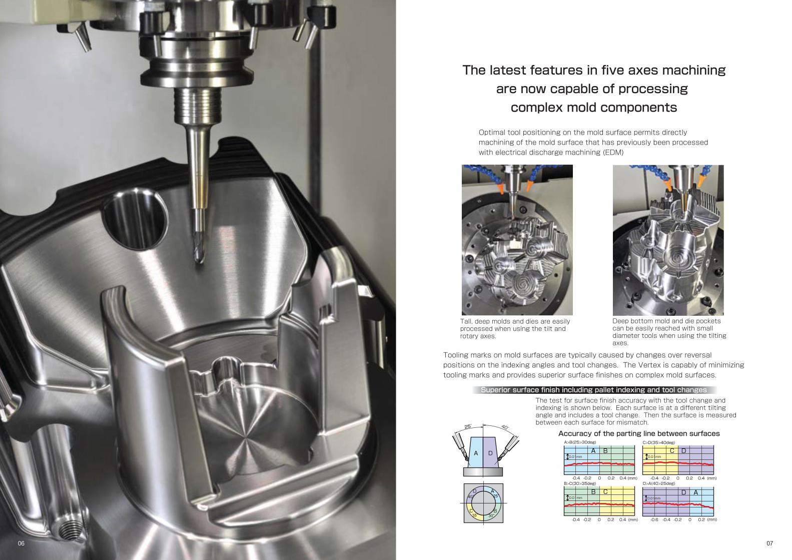
Superior surface finish including pallet indexing and tool changes
Tall, deep molds and dies are easily processed when using the tilt and rotary axes.
Deep bottom mold and die pockets can be easily reached with small diameter tools when using the tilting axes.
The test for surface finish accuracy with the tool change and indexing is shown below. Each surface is at a different tilting angle and includes a tool change. Then the surface is measured between each surface for mismatch.
Tooling marks on mold surfaces are typically caused by changes over reversal positions on the indexing angles and tool changes. The Vertex is capably of minimizing tooling marks and provides superior surface finishes on complex mold surfaces.
Optimal tool positioning on the mold surface permits directly machining of the mold surface that has previously been processed with electrical discharge machining (EDM)
Accuracy of the parting line between surfaces
The latest features in five axes machining
are now capable of processing
complex mold components
40° 25°
A
A
A
A
D
D
D
D
B
B
B
C
C
C
-0.2-0.4 0.40.20 (mm)
0.01mm
B>C(30>35deg)-0.2-0.4 0.40.20 (mm)
0.01mm
A>B(25>30deg)
-0.2-0.4 0.40.20 (mm)
0.01mm
C>D(35>40deg)
-0.6 -0.2-0.4 0.20
0.01mm
(mm)
D>A(40>25deg)

08 09
Impellers, blisks and turbines blades
can only be machined
in full five axes simultaneous motion
Parts for the aerospace and power generation industry are complicated structures requiring special tooling, tool path generation and motion control. Additionally these types of components are made from difficult to machine materials such as inconel, titanium and nickel alloys. Machine stiffness and accurate motion control are important for extended tool life when using expensive cutters. Mitsui Seiki specifically utilized our extensive knowledge in processing these types of components to develop a machine tool capable of dramatically extending the cutting capabilities in a BT/CAT 40 class of five axes machines.

10 11
Vertex working envelope and control
position for easy part access
"Superior ergonomics for five axes part processing"
This latest generation of five axes machine, with newly designed features, has open up many new applications for end users. Cams, proto type gears and many other parts typically made on application specific machines can now be processed on the Vertex. The Vertex550-5X is built on the concept of providing five axes part processing to the end users ready to upgrade there capabilities and develop new ways to manufacture sophisticated components. This is achieved with superior volumetric accuracy, compact machine design for minimal floor space usage, high efficiency, user friendliness equating to high cost performance in new innovative five axes processing.

12
The Vertex550-5X with its 2m x 3m footprint and part size capacity of φ750 mm by 525 mm height provides outstanding space efficiency for a large capacity five-axes machine tool. Also, the compact design provides efficient machine installation or future machine re-location if necessary. The rigid, compact bed is a cube structure that supports the X, Y, and Z -axes along with the trunnion assembly providing stiffness for rapid axes travel.
13
Vertex 550-5X
Vertex 750-5X
2200
650
450
250
325
φ750
340
520
R195
R220
420350
100
525
200
φ200
325
200
φ200φ800
φ950
Vertex550-5X Vertex750-5X
Interference area with maximum length and diameter tool at ATC
Front side of the machine
Front side of the machine
325
34403000
2000
*The opening width of the front door is 700mm *The opening width of the front door is 820mm
■ Footprint
Reduced floor space increase your profitability The Vertex provides the smallest machine footprint with the largest machining envelop of any machines in its class.
Maximum size of loadable work piece
■Operating environment
Ergonomically designed for easy access to both the control panel and machine envelop
The Y-axis cover is retractable for overhead loading and unloading of heavy fixture and work pieces with crane operation.
Tool loading
Retractable Y-axis cover
Good accessibility
You can change the tools in the ATC magazine from the doors on the back of the machine. If the large coolant tank option is chosen the door for ATC magazine tool change is available on the side of the machine.
Access to the table surface is very easy and comfortable for the operator because of the stationary table design.
900
Flo
or to
tabl
esu
rface
400
Movement of “Cube on” Structure
The three linear axes moves on "top of the box" providing the superior axes support.
XY
Z
AC
The A-axis is driven and supported using both sidewalls of the "box" bed eliminating the need for the table to move in X or Y directions. This unique design contributes to stiffness and volumetric accuracy attributes.
Footprint

15°
15°
76.2
φ44.45φ25.4
14 15
■Machining accuracy
Measured results of machined test pieces shows excellent tolerance capability
Machining accuracy (circularity) of 10 shipped units
■Circularity of taper cone machining
♯1
2.4
3.1
3.9
♯2
3.8
3.4
3.1
♯3
3.6
3.8
3.7
♯4
3.6
3.4
4.4
♯5
4.3
3.8
3.9
♯6
3.9
3.7
3.3
♯7
4.5
3.7
4.1
♯8
3.0
3.4
3.4
♯9
2.9
3.7
4.1
♯10
3.3
3.3
3.5
Minimum
2.4
3.1
3.1
Maximum
4.5
3.8
4.4
Average
3.53
3.53
3.74
Measurement position
Top
Middle
Bottom
No.
1
2
3
4
Measuring location and description Dimensions
φ44.45mm
76.2mm
φ25.4mm
76.2mm
The test taper cone is machined with simultaneous five-axes control using an end mill cutting in shape of with 30 degrees angle taper. The cones circumference is then measured at three locations (top, middle, and bottom), with resultant accuracy a combination of all X, Y, Z, A,and C-axes. (Note: Circularity of a typical five-axes machining center is around 20μm.)
A beveled gear, typically processed on a gear cutting machine, was machined by simultaneous five-axes control on the Vertex. Accuracy results are excellent.
■Pitch accuracy of tapered-hole machined by simultaneous four-axes control
■Rotary/tilted indexing accuracies
■Helical bevel gear tooth accuracy on machined gear
This type of taper hole machining requires simultaneous four axes of motion. For superior results in diameters and pitch tolerances, the machine geometry and motion control accuracy must be exceptional. This is a tough task for machines but the Vertex has attained outstanding accuracies; diameter difference between two holes is 4μm or less and the pitch accuracy is 5μm.
【Material】STAVAX 【Tool used】φ12 end mill 【Machining conditions】Spindle speed : 7,247 min-1 Feed rate : 594 mm/min
* The most difficult test for conducting a precise circularity check is utilizing a test piece with relatively small diameter (approx. φ150 mm). This type of sample tests are the most severe condition. The measurements (made at top, middle and bottom of taper) show the true capability of full five- axes geometrical capability.
*The figure below shows color coded size errors of the teeth sur faces measured with a 3-D measurement instrument. The errors of all surfaces are within the accuracy ranges of 7.5μm or less.
By fixing the A-axis at a 15 degree angle and utilizing the X, Y, Z and C- axes in a simultaneous cutting motion on the two bores, the Vertex resultant is a tapered hole pitch accuracy of 5μm.
For a cylindrical (non-tapered) hole, the pitch positioning accuracy is 0.5μm.
Error
Hole A
Hole B
φ-0.0038mm
-0.0051mm
φ-0.0016mm
0.0005mm
7.5 ~ 11.3
3.7 ~ 7.5
0.0 ~ 3.7
-3.7 ~ 0.0
-7.5 ~ -3.7
-11.3 ~ -7.5
Size errors (μm)
Measurement resultsφ
150mm
Unit: μm
The following accuracies were measured on a finished machined aluminum test piece (size: 110 mm×110 mm) using five-face indexing. This data proves the high indexing accuracy of the Vertex.
1. Distance between a tooling hole on the top surface (Surface E) and 4 side faces (Surfaces A to D) 2. Indexing angles at 45, 112.5 and 22.5 degrees 3. Perpendicularity between the top surface and each of the four side faces, and between the two adjacent faces of the four side faces.
Top Middle
Bottom
Taper hole diameter difference
Taper hole pitch
Cylindrical hole diameter difference
Cylindrical hole pitch
A
A
C
D
B
B
E
1
5
6
3
4
2
7
5
Positioning accuracy(unit:mm) Angle(unit:degree) Squareness(unit:mm)
1
55
-0.0051
2
55
0.0017
3
55
0.0063
4
55
0.0067
5
45
-0.0025
6
112.5
0.0003
7
22.5
0.0001
E A
0.0009
E B
0.0013
E C
0.0025
E D
0.0011
A B
0.0013
B C
0.0013
C D
0.0015
D A
0.0037
Measurement item
Mesurement point
Tolerance
Error

16 17
■Tilt rotary table assembly
The tilt rotary table is the core component of the Vertex five-axes machines. This delivers high-speed indexing as well as high accuracy.
Indexing accuracy and repeatability measurement of 10 shipped units
■High accuracy indexing, high accuracy repeatability
4.0
6.0
2.0
3.0
♯1
0.9
1.3
0.5
0.3
♯2
0.7
1.0
0.5
0.4
♯3
1.3
1.4
0.5
0.5
♯4
1.0
1.1
0.7
0.6
♯5
0.6
0.7
0.4
0.5
♯6
0.6
0.3
0.3
0.2
♯7
0.5
0.7
0.6
0.7
♯8
0.7
1.1
0.5
0.4
♯9
2.0
1.2
0.5
0.4
♯10
0.7
0.8
0.3
0.4
Maximum
2
1.4
0.7
0.7
Minimum
0.5
0.3
0.3
0.2
Average
0.9
0.96
0.48
0.44
C-axis
A-axis
C-axis
A-axis
Indexing
accuracy Repeatability
Unit
±sec.
±sec.
±sec.
±sec.
Indexing accuracy and repeatability is very important in five axes machines. An angle error of 1 arc second will result in an error of 1μm in 200 mm away from the center of rotation. The figure on the right shows an example of φ400 mm table being measured for accuracy.
Mitsui Seiki know-how through decades of our in-house manufacturing of high-accuracy rotary tables used for jig borers and many styles of five axes trunnion machines not only provides superior accuracy but also high reliability of the table assemblies and its components.
Either the special drive gear system or DD-motor version are available for both rotating axis (C-axis) and tilting axis (A-axis). This allows the end user to choose the optimal table drive system to fit the component application requirement.
■Benefits of φ225 tables The interference is avoided while processing small-size work piece machining. (See figures on right). ・Quick start and stopping with high-speed rotation ・Smooth rotation without backlash ・Permit components turning (similar to lathe processing).
The C axis with the DD motor is capable of turning at a maximum rotation speed of 1,000 min-1.
φ400 table φ225 table
・The table and spindle head interfere with each other. ・To avoid this interference, either the part is raised with the fixture or a longer tool is required.
・The table and spindle head do not interfere with each other
Rotating axis (C-axis)
Standard
φ400mm
350kg
φ750× 525mm
50min-1
Option 1
120kg
200min-1
Option 2
DD motor
90kg
1000min-1
φ250×300mm φ950×600mm
φ225mm
Special gear Special gear
Table dimensions
Table drive
Maximum weight load
Maximum part size (diameter x height)
Maximum RPM
Indexing accuracy
Repeatability
±4 arc sec
±2 arc sec
±4 arc sec
±2 arc sec
560 320
Tilting axis (A-axis)
Standard
Special gear
30min-1
Option 1
DD motor
100min-1
Standard
Special gear
20min-1
±6 arc sec
±3 arc sec
Table drive
Maximum RPM
Indexing accuracy
Repeatability
±6 arc sec
±3 arc sec Table withφ225 C-axis
Standard value
Interference
Standard
φ500mm
500kg
φ950× 650mm
40min-1
Option 1
φ630mm
400kg
40min-1
Vertax 550-5X Vertax 750-5X
Vertax 550-5X Vertax 750-5X
50
19.1
1411.9
9.87.97.15.7
18.51512.3
1110
(0.15)
(0.1)
5000750012000
1800025000
28.6
Spindle Speed(min-1)
25,000min-1Spindle
Torque-Power diagram
15,000min-1Spindle
Torque-Power diagram
Spindle Speed(min-1)
Power (kW)
Torque (N-m)
30min
25%ED
Cont.
Cont.
30min
25%ED
1.00
0.50
0.00
-0.50
-1.00
1.00
0.50
0.00
-0.50
-1.00
-1.50
-2.000 100 200 300 400 500 600 0 100 200 300 400 500 600 0 100 200 300 400 500 600
2.50
2.00
1.50
1.50
Error(μm)
1.00
0.50
0.00
-0.50
-1.00
2.50
2.00
1.50
Error(μm)
Error(μm)
Target(mm) Target(mm)Target(mm)
2.62μmX 2.77μmY 2.82μmZ
18 19
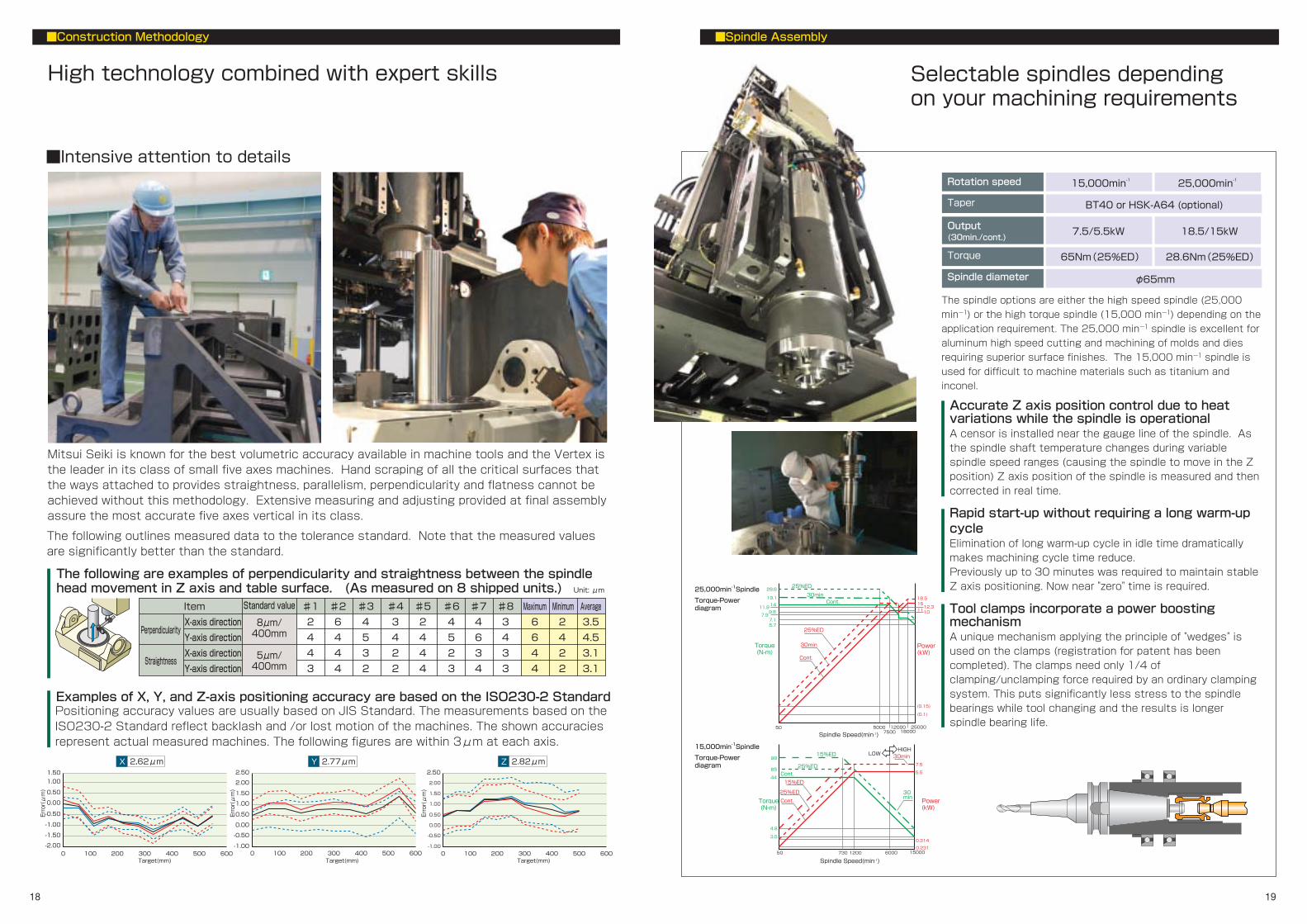
High technology combined with expert skills Selectable spindles depending on your machining requirements
■Construction Methodology
■Spindle Assembly
■Intensive attention to details
Mitsui Seiki is known for the best volumetric accuracy available in machine tools and the Vertex is the leader in its class of small five axes machines. Hand scraping of all the critical surfaces that the ways attached to provides straightness, parallelism, perpendicularity and flatness cannot be achieved without this methodology. Extensive measuring and adjusting provided at final assembly assure the most accurate five axes vertical in its class.
The spindle options are either the high speed spindle (25,000
min-1) or the high torque spindle (15,000 min-1) depending on the
application requirement. The 25,000 min-1 spindle is excellent for
aluminum high speed cutting and machining of molds and dies
requiring superior surface finishes. The 15,000 min-1 spindle is
used for difficult to machine materials such as titanium and
inconel.
Accurate Z axis position control due to heat variations while the spindle is operational A censor is installed near the gauge line of the spindle. As the spindle shaft temperature changes during variable spindle speed ranges (causing the spindle to move in the Z position) Z axis position of the spindle is measured and then corrected in real time.
Rapid start-up without requiring a long warm-up cycle Elimination of long warm-up cycle in idle time dramatically makes machining cycle time reduce. Previously up to 30 minutes was required to maintain stable Z axis positioning. Now near "zero" time is required.
Tool clamps incorporate a power boosting mechanism A unique mechanism applying the principle of "wedges" is used on the clamps (registration for patent has been completed). The clamps need only 1/4 of clamping/unclamping force required by an ordinary clamping system. This puts significantly less stress to the spindle bearings while tool changing and the results is longer spindle bearing life.
Rotation speed
Taper
Output (30min./cont.)
Torque
Spindle diameter
15,000min-1
18.5/15kW
28.6Nm(25%ED) 65Nm(25%ED)
7.5/5.5kW
BT40 or HSK-A64 (optional)
φ65mm
25,000min-1
Examples of X, Y, and Z-axis positioning accuracy are based on the ISO230-2 Standard
The following are examples of perpendicularity and straightness between the spindle head movement in Z axis and table surface. (As measured on 8 shipped units.) Standard value
8μm/ 400mm
5μm/ 400mm
♯1
2
4
4
3
♯2
6
4
4
4
♯3
4
5
3
2
♯4
3
4
2
2
♯5
2
4
4
4
♯6
4
5
2
3
♯7
4
6
3
4
♯8
3
4
3
3
Maximum
6
6
4
4
Minimum
2
4
2
2
Average
3.5
4.5
3.1
3.1
Perpendicularity
Straightness
X-axis direction
Y-axis direction
X-axis direction
Y-axis direction
Positioning accuracy values are usually based on JIS Standard. The measurements based on the ISO230-2 Standard reflect backlash and /or lost motion of the machines. The shown accuracies represent actual measured machines. The following figures are within 3μm at each axis.
Unit: μm
Item
The following outlines measured data to the tolerance standard. Note that the measured values are significantly better than the standard.
50 1200730 6000 15000
7.5
5.5
0.314
0.231
Power (kW)
65
98
44
4.8
3.5
Torque (N-m)
Cont.
30 min
25%ED
15%ED 30minHIGH
LOW
Cont.
25%ED
15%ED

■Examples of coolant tank configurations
"Minimum Quantity Lubrication" (MQL) is generally called semi-dry processing. Air flow and a small amount of oil (2 to 16 ml per hour depending on the material being machined) is provided to the cutting tool edge. This method is an excellent approach when machining steel that requires superior surface finishes.
20 21
Machine designed for efficient chip evacuation Optional chip discharge location available to fit your machine layout requirements
■Chip handling systems ■ATC
■Maintenance
Effective chip clearing form the work zone The cutting chips and coolant fall directly into the chip conveyor under the table. Then the chips are quickly discharged by a conveyance system, the coolant cleaned and re- circulated.
Complex part processing machines require an increased number of tools. The Vertex ATC is capable of loading 40 tools with our standard specification, 60 are optionally available and up to 128 by installing separate magazine extension unit at the back of the machine.
Main tank
Sub tank
Tank capacity
Optional
×
△ (conditional)
○
×
×
×
Standard
200L
─
type1
200L
250L
type2
400L
250L
type3
410L
─
type4
750L
─
○
○
○
×
○
○
○
○
○
×
○
○
○
○
○
○
○
○
○
○
○
○
○
○
Rear of the machine Right side of the machine
Right side → rear of the machine
《type2》 《type3》 《type4》 High-capacity coolant tank for grinding applications Provided with bag filters and paper filters
Chip discharge direction
Number of loadable tools
Maximum tool length
Maximum tool weight
Standard
40 60 128
Optional
300mm
φ125mm
φ90mm
10kgf
φ70mm
5kgf
Machine maintenance access to all units is located at the rear of the machine permitting easy checking and maintenance of the machine.
The spindle chiller unit and hydraulic unit are placed inside the door at the rear of the machine. This simple design permits a compact machine with minimized floor space.
Separate 128-magazine extension unit
*Some of these examples are customized specifications and Mitsui Seiki will customize your special requirement.
Options available
Center through coolant
Oil skimmer
Work piece cleaning
Drum filter
Cyclonic filter
Cutting oil cooler
Machine unit
Maximum
tool diameter
With adjacent tool
Without adjacent tool
Flood coolant(Standard)Air blow or MQL(Option)Through the spindle coolant(Option)
Vertex 550-5X 350mm Vertex 750-5X

Mitsui Seiki will design the automated system to fit your part processing requirements EROWA 6APC (□400 pallet) system
Robotic BT50 AWC (Auto Work Changer) system
Robotic □400 pallet FMS system
22 23
■Examples of automated systems
Designed for unmanned operations and "lights out" parts processing
■Software
Functions to support five axes parts processing
The Vertex includes the following NC functions essential to five-axes processing as standard
● Tool tip control for five-axis processing
● Slanted surface processing
● AI contour control 2
● Processing conditional selection functions
The following functions are also provided as standard to accommodate expanding program data volume.
● Program memory capacity: 2 MB (5120 m)
● Additional program registration: 1 (up to 1000)
● Fast data server function (with 1 GB card)
For highly-accurate five-axes processing, it is necessary to precisely determine a center of the rotating/tilted axes. It is desirable that centers of the two axes are measured on a regular basis, and is especially important to check them before a finishing process. A dedicated centering gauge, AMCS (Automatic Measurement Correction System), and set-up guidance screen are optionally available with the Vertex. By operating the machine in accordance with instructions on the screen, the center of A or C-axis can be precisely and easily located.
Dedicated centering gauge
Guidance screen Determining C-axis center of rotation Determining A-axis center of rotation
+
A and C axes rotating-coordinate calculation macro To correct a positional point to the part program zero location as it indexes through a five-axes coordinate system, the combined indexing angle changes must be determined. This is very difficult to find. This software is designed to make automatic calculations for the correction. By determining the center of the rotating/tilted axis, in advance, using the "rotating/tilted axis centering function" in the previous section helps the user make the precise coordinate setup and point-of-origin correction of the work piece.
Mitsui Seiki Rotary Table Dynamic Fixture Offset In the event that a machining part program point of origin (part program zero location) and a datum point of the work piece are not aligned, this function allows the machine to continuously correct the machining point of origin as the rotating axis moves, by presetting the misalignment scale in the fixture offset. It allows the user to have consistent simultaneous five-axes processing with the same part program, even when a work piece is misaligned every time it is loaded. This function is not the FANUC "Rotary table dynamic fixture offset" and is a Mitsui Seiki exclusive feature.
Pre-installed standard NC functions assist in five-axes processing
Centering function for rotating/tilted axis

φ125
φ90
48
6
6.3
32 26
18
16
26.526.5
min.42
max.φ53
φ63
φ53
φ53
taper 1/10
HSK-A63(optional)
30
30
42
300350
300350
300350
300350
φ100
φ125
φ63
φ90
19
3 6
3
17
29 92.4
65.4 25
φ53
φ63
30°
2
16.1
22.6 22.6 1016.5
44.45
PULL STUD BOLT(JIS)
BT40
X
ZZ1
Z Z
Z1C
X1 X1
Y
Y1 Y1
Y
Y1 Y1
Y2
24 25
■Floor Layout Diagram (standard specifications)
■Interference Diagram (standard specifications)
■Tools
■Table Top Diagram (standard specifications)
X
550
750
X1
275
375
Y
600
800
Y1
300
400
Y2
100
150
Z
500
700
Z1
100
150
Z1
400
500
Vertex 550-5x
Vertex 750-5x
Vertex 550-5xVertex 750-5x
Vertex 550-5xVertex 750-5x
Vertex 550-5xVertex 750-5x
Vertex 550-5xVertex 750-5x
Unit:mm
12-M12 P1.75×22
8-M12 P1.75×22
8-M12 P1.75×22
P.C.D 350
P.C.D 250
P.C.D 150
22.5°
φ400
Details of M12 tap hole
22
90°
3.2a
φ14.5
3015
639
2000
455
525
833
2300
900
3485
3133
833
2300
2005 455
12-M12 P1.75×22
12-M12 P1.75×22
8-M12 P1.75×22
P.C.D 450
P.C.D 290
P.C.D 180
22.5°
φ500
22
Details of M12 tap hole
90°
3.2a
φ14.5
4472205
2652
2300
1345
3645
1755
639
460
1740
2200
455
1803260
3440
925
2710
floor
to ta
ble
surfa
ceflo
or to
tabl
esu
rface

26 27
● SPECIFICATIONS
Stroke Table Spindle Feed rate Position Transducer ATC NC unit Accuracy Power and Air Machine size
Item UnitSpecification
X-axis Y-axis Z-axis A-axis C-axis Distance from table surface to spindle Table size Max. work size (diameter x height) Max. permissible load Surface of table Height from floor to table surface Spindle speed Taper Spindle motor (30min/cont. rating) Max. spindle torque (25%ED/cont.rating) Spindle diameter Rapid traverse Cutting feed Min. resolution Min. feedback XYZ axis AC axis Tool storage capacity Max. tool length Max. tool diameter of tool to be changed Max. tool diameter of tool to be changed without adjacent tools Max. tool weight Tool selection mode Positioning accuracy Repeatability Power required Air required Footprint (W×L×H) Shipment size (W×L×H) Machine weight
mm mm mm ° ° mm mm mm kg mm
min-1
kW N-m mm
mm/min min-1
mm/min min-1
mm ° mm mm
mm kgf mm sec. mm sec. mm mm Kg
+15~-105(0.0001°dec.) 360(0.0001°dec.)
Absolute Iinear scale Absolute inductsyn
40 300 350
φ90
φ125 10
Fixd pot number,randam selection FANUC 31i ±0.001 A:±6 C:±4 ±0.001 A:±3 C:±2 50KVA
0.5MPa or more, 1200NL/min or more
About 9,500 About 12,500
550-5X 750-5X
550 600 500
750 800 700
100~600 φ400
φ750×525(with limitation) 350(A axis is horizontal)
28-M12(PCD150&250&350) 900
150~850 φ500 (optionalφ630)
φ950×650(with limitation) 500(A axis is horizontal)
32-M12(PCD180&290&450) 925 《25,000 or15,000 is available》
50~25,000 50~15,000 ISO 7/24 Taper No.40
18.5/15 7.5/5.5 28.6/14 65/44
φ65
《25,000 or15,000 is available》 50~25,000 50~15,000 ISO 7/24 Taper No.40
18.5/15 7.5/5.5 28.6/14 65/44
φ65 48,000
A:30 C:50 0.1~48,000 max A:30 C:50
0.0001 0.0001
48,000 A:20 C:40 0.1~48,000 max A:15 C:30
0.0001 0.0001
2,050×3,485×3,113 2,050×3,485×2,800
2,250×3,800×3,645 2,250×3,800×3,190
● STANDARD NC SPECIFICATIONS (FANUC 31i-A5)
● OPTIONAL SPECIFICATION (MACHINE)
●OPTIONAL SPECIFICATION (NC)
Cs contouring control
Inch / metric conversion
Sequence number comparision and stop
Program restart
Manual handle interruption
Exponential interpolation
Pole coordinate interpolation
Cylindrical interpolation
Involute interpolation
Hypothetical axis interpolation
Spiral interpolation, conical interpolation
Smooth interpolation
Nano smoothing
High-speed smooth TCP
NURBS interpolation
3 dimensional circular interpolation
Simultaneously control : 5 axis
HRV3 control
Stored stroke check 2, 3
Single direction positioning
Helical interpolation
High speed skip
3rd/4th reference position return
Bell-shaped acceleration/ deceleration after cutting feed interpolation
Linear acceleration/ deceleration before cutting feed interpolation
Automatic acceleration/deceleration
Cutting feed speed : F5digit 1mm/min
※AI contour control Ⅱ
Bell-shaped acceleration/deceleration before look-ahead interpolation
Additional optional block skip 9
Dual contact system
Pull stud
60 tools ATC
Ceiling shower coolant
Chip conveyor with dram filter
Side discharge type chip conveyor (with 410L tank )
Through the spindle coolant
system
Cyclone filter
Inverse time feed
One-digit F code feed
High-speed processing
Look ahead blocks expansion(Max.1000)
Jerk control
Polar coordinate command
Workpiece coordinate system pair
Interruption type custom macro
Optional chamfering ad corner R
Automatic corner override
Scaling
Programmable Mirror image
Figure copy
F 15 tape format
Pattern data input
Workpiece coordinate system preset(G92.1)
Custom macro
Additional custom macro common variables 600
Custom software size 2MB
Coordinate system rotation
※Tilted working plane command
Macro executor
C language executor
Spindle override
Spindle orientation
Rigid tapping
99 tool offset pairs
Tool compensation memory C
※Tool offset
Coolant chillier
Sub tank (250L)
Oil skimmer
Mist collector
Air blow (external nozzle type)
MQL system
Chip bucket
Splash gun(For work cleaning)
Air gun
Circuit protection breaker
Work counter
Elapse meters
Manual pulse handle (w/ e-stop )
Operator support function
Compensation of spindle thermal displacement function (sensor type)
Machine leveling jack bolts and plate
※Tool center point control for 5-axis machining
Cutter or tool nose radius compensation(G40,G41,G42)
※Part program storage (2Mb)5,120m
Number of registerable programs expansion 1(1000)
Background editing
Extended part program editing
※Machining condition selecting function
Graphic display
Reader / puncher interface 1
※Fast DATA SERVER+1MB ATA Flush card
External data input
Fast Ethernet
10.4 LCD color display
100V 2A outlet
Weekly timer
I/F for fire extinguisher
RS232C I/F
Part probing system AMCS-7S/7H
Tool probing system AMCS-7T
Tool breakage detection
Auto.tool length measure (ATLS) with tool brakage detection
Laser type tool length and diameter
Z-axis original position setting tool
Reference square
Rotary and tilting axis alignment gage
Guidance function Rotary and tilting axis original setting
3 dimensional cutter compensation
Tool offset pairs
Rotary table dynamic fixture offset
Cutter compensation for 5-axis machining
Work setting error compensation
Tool life management function (Max. 256 pairs)
Additional Tool life management function (Max. 1024 pairs)
Part program storage size
Number of registerable programs expansion 2(4000)
15.0"Color LCD
HSSB
FOCAS 2
●STANDARD MACHINE SPECIFICATIONS
Whole machine cover
Door interlock
Spindle chiller (inverter control)
Coolant system (200L tank & pump)
Scraper type chip conveyor ×1
Automatic power breaker
Work light (LED×1)
Signal tower (3 lights)
HSK-A63
Big Plus
JIS
MAS Ⅰ
MAS Ⅱ
400L tank
750L tank
1MPa
3MPa
1500Kcal/H
3000Kcal/H
48 pairs
300 pairs
200
400
499
999
4MB(10240m)
8MB(20480m)
※As option in case of 3 axis machine
XYZ axis AC axis XYZ axis AC axis XYZ axis AC axis
XYZ axis AC axis XYZ axis AC axis