mixed signal oscilloscopes 300 mhz 400 mhz 500 mhz … · mixed signal oscilloscopes 300 mhz | 400...
TRANSCRIPT
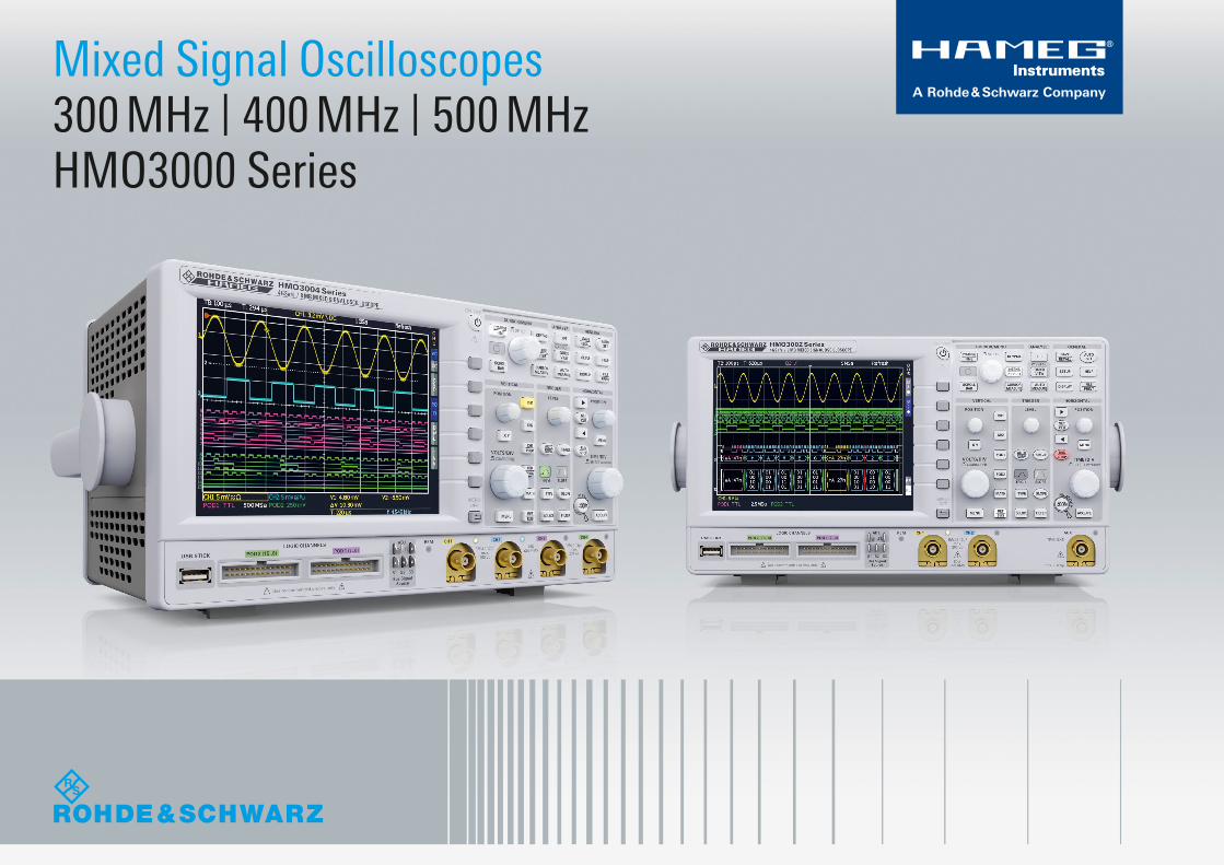
Mixed Signal Oscilloscopes300 MHz | 400 MHz | 500 MHz HMO3000 Series
HM
O 3
004
Ser
ies,
500
MH
z w
ith 4
Cha
nnel
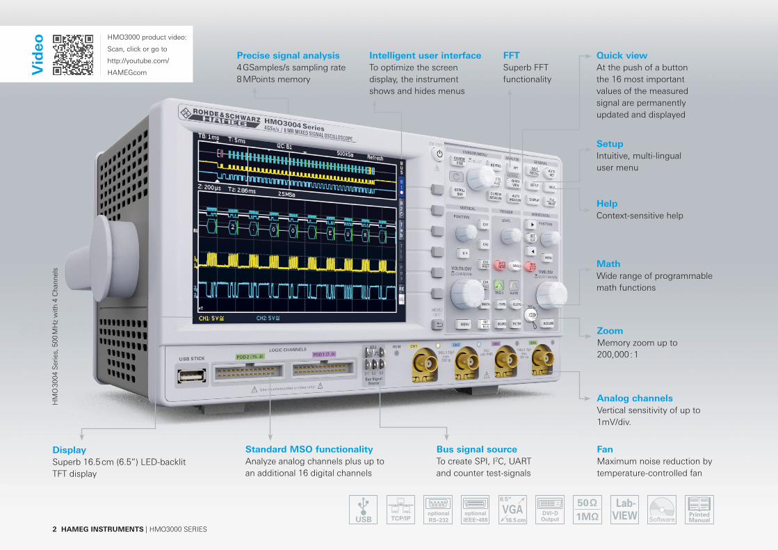
sIntelligent user interfaceTo optimize the screen display, the instrument shows and hides menus
Precise signal analysis4 GSamples/s sampling rate8 MPoints memory
Vid
eo
SetupIntuitive, multi-lingualuser menu
FFTSuperb FFT functionality
HelpContext-sensitive help
Quick viewAt the push of a button the 16 most important values of the measured signal are permanently updated and displayed
FanMaximum noise reduction by temperature-controlled fan
ZoomMemory zoom up to 200,000 : 1
Analog channelsVertical sensitivity of up to 1mV/div.
Bus signal sourceTo create SPI, I2C, UART and counter test-signals
Standard MSO functionalityAnalyze analog channels plus up to an additional 16 digital channels
MathWide range of programmable math functions
DisplaySuperb 16.5 cm (6.5”) LED-backlit TFT display
2 HAMEG INSTRUMENTS | HMO3000 SERIES
HMO3000 product video:
Scan, click or go to
http://youtube.com/
HAMEGcom

More information | www.hameg.com 3
up to 500 MHz…High sensitivity, multi-functionality and a great price – that‘s what distinguishes the HAMEG HMO3000 oscilloscope series.
Key facts 4 GSa /s real time, low noise fl ash A /D converter 8 MPts memory, zoom up to 200,000:1 MSO functionality included as standard(HO3508/HO3516 logic probe with 8/16 channels required)
Automatically or manually adjustable memory depth Vertical sensitivity up to 1 mV/div. Trigger modes: slope (A/B), pulse width, video, logic, serial buses (optional), hold-off
Serial bus trigger and hardware accelerated decode incl. list view. Options: I2C + SPI + UART/RS-232 (HOO10/HOO11), CAN + LIN (HOO12)
28 auto-measurement parameters plus statistics, formula editor, ratio cursor 6-digit hardware counter FFT up to 64 kPts (dBm, dBV, Vrms) Pass/fail test based on masks Automatic search for user-defi ned events Display: 12 div. x-axis, 20 div. y-axis (Virtual Screen) 2x USB for mass storage, Ethernet/USB dual interface for remote control
HMO 3000 Series
Application How the HAMEG HMO3000 meets your needsEngineering lab Adjustable memory depth
Advanced math functions available as standard, math on math possible Automeasurement for 28 user-defined parameters Memory zoom function up to 200,000:1
Analog circuit design
Low-noise amplifier and A/D converter 1 mV/div. sensitivity 50 Ω/1 MΩ input impedance, switchable Bandwidth upgrades via software options
Embedded debugging
Mixed signal option (MSO) with 16 logic channels Serial bus trigger and hardware-accelerated decode 6-digit hardware counter Superb FFT functionality
Production environment
Remote control for automated data acquisition Pass/fail tests based on user-defined masks with error signal output Automatic signal measurement at the push of a button USB/RS-232, Ethernet or GPIB (IEEE 488) interfaces
General purpose and education
Fast boot time Low-noise, intelligent temperature management Extended display size through Virtual Screen technology DVI-D output for external display
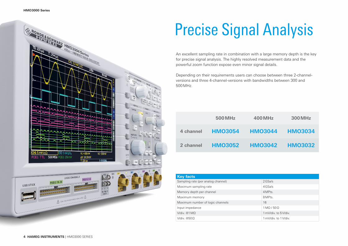
Precise Signal AnalysisAn excellent sampling rate in combination with a large memory depth is the key for precise signal analysis. The highly resolved measurement data and the powerful zoom function expose even minor signal details.
Depending on their requirements users can choose between three 2-channel-versions and three 4-channel-versions with bandwidths between 300 and 500 MHz.
500 MHz 400 MHz 300 MHz
4 channel HMO3054 HMO3044 HMO3034
2 channel HMO3052 HMO3042 HMO3032
4 HAMEG INSTRUMENTS | HMO3000 SERIES
Key factsSampling rate (per analog channel) 2 GSa/s
Maximum sampling rate 4 GSa/s
Memory depth per channel 4 MPts.
Maximum memory 8 MPts.
Maximum number of logic channels 16
Input impedance 1 MΩ / 50 Ω
V/div. @1 MΩ 1 mV/div. to 5 V/div.
V/div. @50 Ω 1 mV/div. to 1 V/div.
HMO 3000 Series
More information | www.hameg.com 5
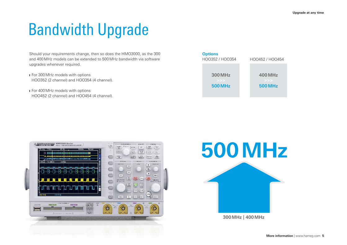
Bandwidth UpgradeShould your requirements change, then so does the HMO3000, as the 300 and 400 MHz models can be extended to 500 MHz bandwidth via software upgrades whenever required.
For 300 MHz models with options HOO352 (2 channel) and HOO354 (4 channel).
For 400 MHz models with options HOO452 (2 channel) and HOO454 (4 channel).
OptionsHOO352 / HOO354 HOO452 / HOO454
Upgrade at any time
500 MHz
300 MHz | 400 MHz
300 MHz >>>
500 MHz
400 MHz >>>
500 MHz
6 HAMEG INSTRUMENTS | HMO3000 SERIES
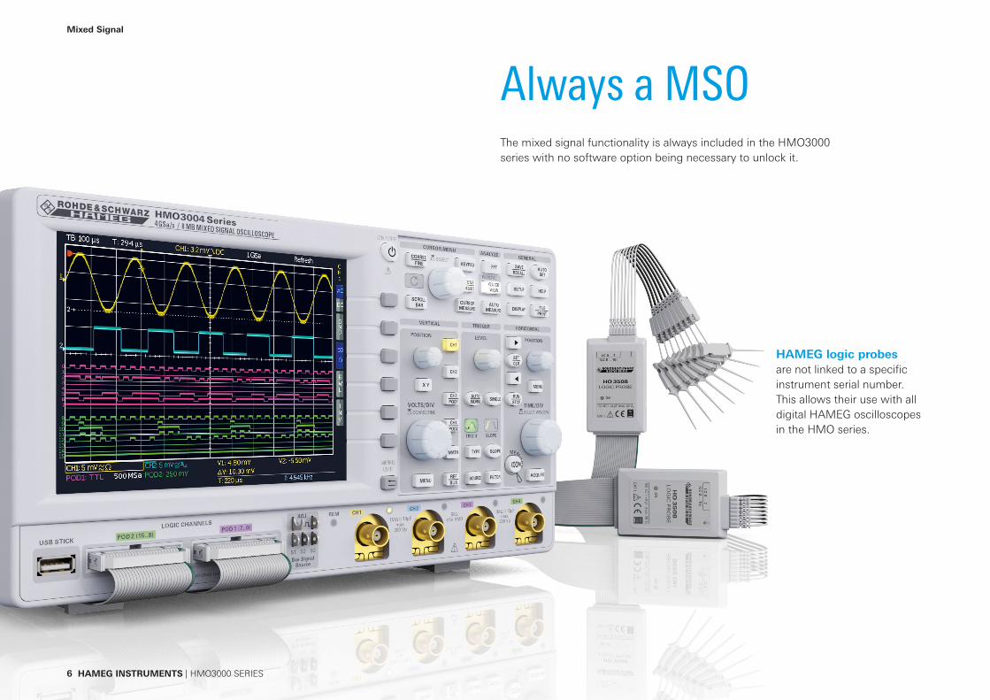
Always a MSOThe mixed signal functionality is always included in the HMO3000 series with no software option being necessary to unlock it.
HAMEG logic probesare not linked to a specifi c instrument serial number. This allows their use with all digital HAMEG oscilloscopes in the HMO series.
Mixed Signal
More information | www.hameg.com 7
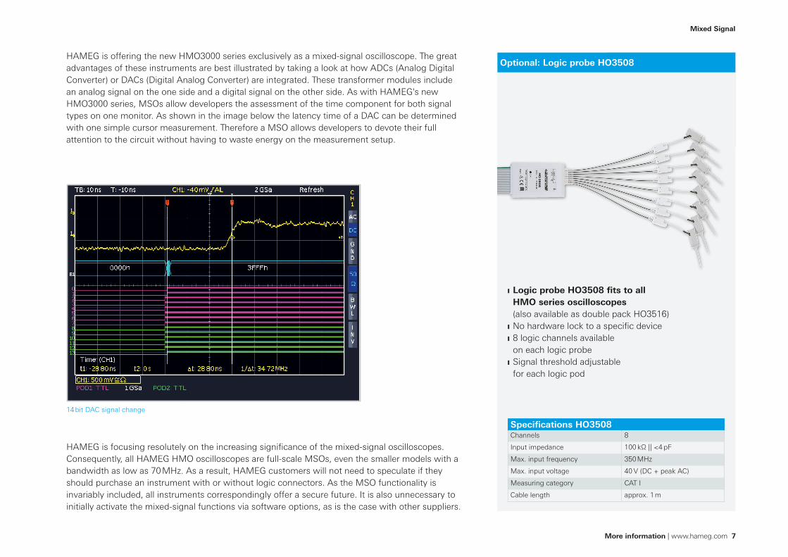
Optional: Logic probe HO3508
Logic probe HO3508 fi ts to all HMO series oscilloscopes (also available as double pack HO3516)
No hardware lock to a specifi c device 8 logic channels available on each logic probe
Signal threshold adjustable for each logic pod
Specifi cations HO3508Channels 8
Input impedance 100 kΩ || <4 pF
Max. input frequency 350 MHz
Max. input voltage 40 V (DC + peak AC)
Measuring category CAT I
Cable length approx. 1 m
HAMEG is offering the new HMO3000 series exclusively as a mixed-signal oscilloscope. The great advantages of these instruments are best illustrated by taking a look at how ADCs (Analog Digital Converter) or DACs (Digital Analog Converter) are integrated. These transformer modules include an analog signal on the one side and a digital signal on the other side. As with HAMEG's new HMO3000 series, MSOs allow developers the assessment of the time component for both signal types on one monitor. As shown in the image below the latency time of a DAC can be determined with one simple cursor measurement. Therefore a MSO allows developers to devote their full attention to the circuit without having to waste energy on the measurement setup.
HAMEG is focusing resolutely on the increasing signifi cance of the mixed-signal oscilloscopes. Consequently, all HAMEG HMO oscilloscopes are full-scale MSOs, even the smaller models with a bandwidth as low as 70 MHz. As a result, HAMEG customers will not need to speculate if they should purchase an instrument with or without logic connectors. As the MSO functionality is invariably included, all instruments correspondingly offer a secure future. It is also unnecessary to initially activate the mixed-signal functions via software options, as is the case with other suppliers.
14 bit DAC signal change
Mixed Signal

8 HAMEG INSTRUMENTS | HMO3000 SERIES
Frequency AnalysisFFT functionality
Due to the outstanding FFT functionality of the HMO series oscilloscopes signals can also be analysed in the frequency domain with up to 65,536 points. Additional practical tools such as cursor measurement as well as peak-detect-functions are also available. They allow engineers to complete their analysis significantly faster, also in the frequency domain.
Easy analysis in frequency domainQuite often the distortion of input signals cannot be detected with the naked eye. For instance, the sine wave signal displayed in figure 1 appears to be undistorted. Only the frequency spectrum (figure 2) - available with just one touch of a button - clearly displays additional harmonics that occur as harmonic oscillations for multiples of the basic frequency.
For non-periodic input signals most instruments offer the option to trigger the spectrum at just the right moment to then check it in “STOP” mode at a later time. However, at that point, many oscilloscopes with FFT functionality calculate the spectrum only once and store the result in the memory. The base time signal will no longer be used for the calculation. Consequently, an investigation of all parts of the signal will no longer be possible.
HMO series oscilloscopes work differently: Since FFT is also active for previously stored signals, it is possible to subsequently analyze any sections of those signals captured in single shot mode or stop mode with an adjustable window width. Figure 3 shows a sine burst signal in the time domain. Pushing the FFT button will switch the oscilloscope into the frequency domain. Users can choose between various measurement windows like the
Figure 1: A sinusoid signal that at first sight appears undistorted Figure 2: The frequency spectrum exposes the signal distortion Figure 3

More information | www.hameg.com 9
FFT functionality
Figure 5
„rectangular“ type that has been used in figure 4. Although this window type captures frequencies at a high degree of accuracy, it is also accompanied by more noise. In order to suppress this disturbing interference users can for instance choose the Hanning window. The impact on the spectrum is visible in figure 5 (see device screen).
Figure 4
10 HAMEG INSTRUMENTS | HMO3000 SERIES
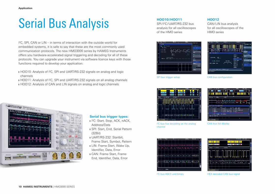
Serial Bus AnalysisI2C, SPI, CAN or LIN – in terms of interaction with the outside world for embedded systems, it is safe to say that these are the most commonly used communication protocols. The new HMO3000 series by HAMEG Instruments offers you hardware-accelerated signal triggering and decoding for all of these protocols. You can upgrade your instrument via software licence keys with those functions required to develop your application:
HOO10: Analysis of I2C, SPI and UART/RS-232 signals on analog and logic channels
HOO11: Analysis of I2C, SPI and UART/RS-232 signals on all analog channels HOO12: Analysis of CAN and LIN signals on analog and logic channels
Serial bus trigger types: I2C: Start, Stop, ACK, nACK, Address/Data
SPI: Start, End, Serial Pattern (32Bit)
UART/RS-232: Startbit, Frame Start, Symbol, Pattern
LIN: Frame Start, Wake Up, Identifier, Data, Error
CAN: Frame Start, Frame End, Identifier, Data, Error
SPI bus trigger setup CAN bus configuration
I2C bus hex decoding on the analog channel
I2C bus ASCII und binary
CAN bus list display
HEX decoded CAN bus signal
HOO10 / HOO11SPI / I2C / UART/RS-232 bus analysis for all oscilloscopes of the HMO series
HOO12CAN / LIN bus analysis for all oscilloscopes of the HMO series
Application
More information | www.hameg.com 11
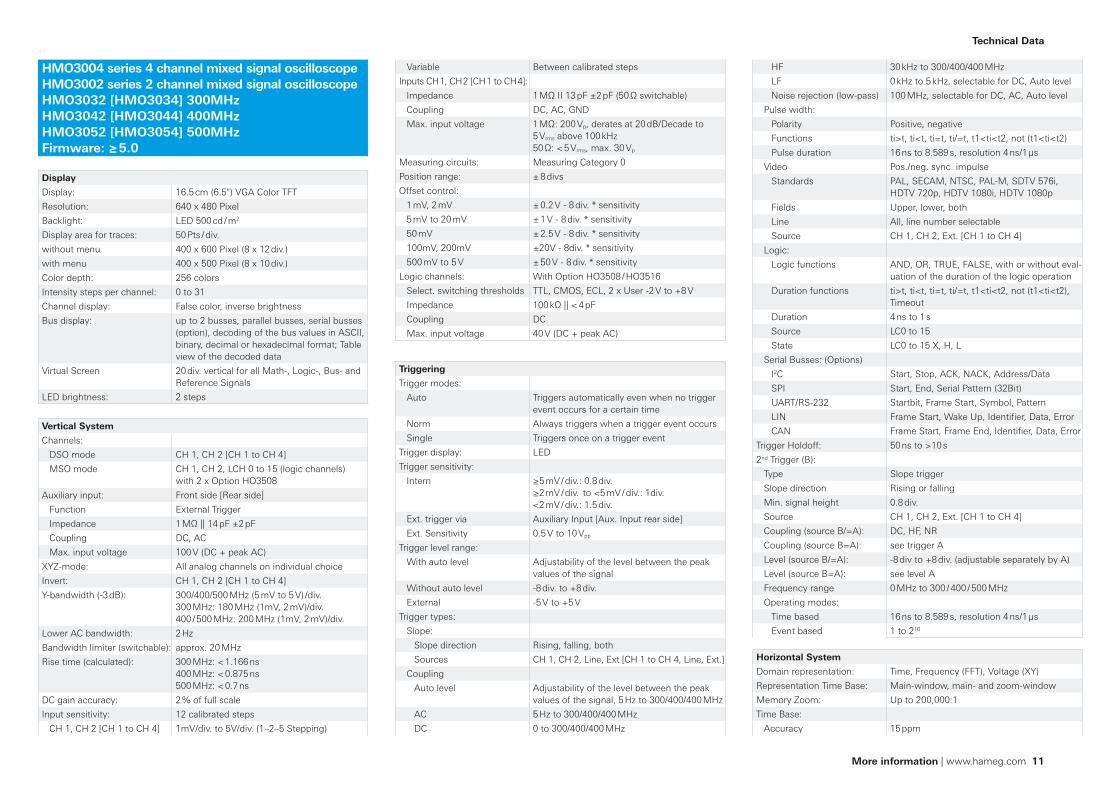
HMO3004 series 4 channel mixed signal oscilloscopeHMO3002 series 2 channel mixed signal oscilloscopeHMO3032 [HMO3034] 300MHzHMO3042 [HMO3044] 400MHzHMO3052 [HMO3054] 500MHzFirmware: ≥ 5.0
Display
Display: 16.5 cm (6.5") VGA Color TFT
Resolution: 640 x 480 Pixel
Backlight: LED 500 cd / m2
Display area for traces: 50 Pts / div.
without menu 400 x 600 Pixel (8 x 12 div.)
with menu 400 x 500 Pixel (8 x 10 div.)
Color depth: 256 colors
Intensity steps per channel: 0 to 31
Channel display: False color, inverse brightness
Bus display: up to 2 busses, parallel busses, serial busses (option), decoding of the bus values in ASCII, binary, decimal or hexadecimal format; Table view of the decoded data
Virtual Screen 20 div. vertical for all Math-, Logic-, Bus- and Reference Signals
LED brightness: 2 steps
Vertical System
Channels:
DSO mode CH 1, CH 2 [CH 1 to CH 4]
MSO mode CH 1, CH 2, LCH 0 to 15 (logic channels) with 2 x Option HO3508
Auxiliary input: Front side [Rear side]
Function External Trigger
Impedance 1 MΩ || 14 pF ±2 pF
Coupling DC, AC
Max. input voltage 100 V (DC + peak AC)
XYZ-mode: All analog channels on individual choice
Invert: CH 1, CH 2 [CH 1 to CH 4]
Y-bandwidth (-3 dB): 300/400/500 MHz (5 mV to 5 V) /div. 300 MHz: 180 MHz (1mV, 2 mV)/div. 400 / 500 MHz: 200 MHz (1mV, 2 mV)/div.
Lower AC bandwidth: 2 Hz
Bandwidth limiter (switchable): approx. 20 MHz
Rise time (calculated): 300 MHz: < 1.166 ns 400 MHz: < 0.875 ns 500 MHz: < 0.7 ns
DC gain accuracy: 2 % of full scale
Input sensitivity: 12 calibrated steps
CH 1, CH 2 [CH 1 to CH 4] 1mV/div. to 5V/div. (1–2–5 Stepping)
Variable Between calibrated steps
Inputs CH 1, CH 2 [CH 1 to CH 4]:
Impedance 1 MΩ II 13 pF ±2 pF (50 Ω switchable)
Coupling DC, AC, GND
Max. input voltage 1 MΩ: 200 Vp, derates at 20 dB/Decade to 5 Vrms above 100 kHz50 Ω: < 5 Vrms, max. 30 Vp
Measuring circuits: Measuring Category 0
Position range: ± 8 divs
Offset control:
1 mV, 2 mV ± 0.2 V - 8 div. * sensitivity
5 mV to 20 mV ± 1 V - 8 div. * sensitivity
50 mV ± 2.5 V - 8 div. * sensitivity
100mV, 200mV ±20V - 8div. * sensitivity
500 mV to 5 V ± 50 V - 8 div. * sensitivity
Logic channels: With Option HO3508 / HO3516
Select. switching thresholds TTL, CMOS, ECL, 2 x User -2 V to +8 V
Impedance 100 kΩ || < 4 pF
Coupling DC
Max. input voltage 40 V (DC + peak AC)
Triggering
Trigger modes:
Auto Triggers automatically even when no trigger event occurs for a certain time
Norm Always triggers when a trigger event occurs
Single Triggers once on a trigger event
Trigger display: LED
Trigger sensitivity:
Intern ≥5 mV / div.: 0.8 div.≥2 mV / div. to <5 mV / div.: 1div.<2 mV / div.: 1.5 div.
Ext. trigger via Auxiliary Input [Aux. Input rear side]
Ext. Sensitivity 0.5 V to 10 Vpp
Trigger level range:
With auto level Adjustability of the level between the peak values of the signal
Without auto level -8 div. to +8 div.
External -5 V to +5 V
Trigger types:
Slope:
Slope direction Rising, falling, both
Sources CH 1, CH 2, Line, Ext [CH 1 to CH 4, Line, Ext.]
Coupling
Auto level Adjustability of the level between the peak values of the signal, 5 Hz to 300/400/400 MHz
AC 5 Hz to 300/400/400 MHz
DC 0 to 300/400/400 MHz
HF 30 kHz to 300/400/400 MHz
LF 0 kHz to 5 kHz, selectable for DC, Auto level
Noise rejection (low-pass) 100 MHz, selectable for DC, AC, Auto level
Pulse width:
Polarity Positive, negative
Functions ti>t, ti<t, ti=t, ti/=t, t1<ti<t2, not (t1<ti<t2)
Pulse duration 16 ns to 8.589 s, resolution 4 ns/1 µs
Video Pos./neg. sync. impulse
Standards PAL, SECAM, NTSC, PAL-M, SDTV 576i, HDTV 720p, HDTV 1080i, HDTV 1080p
Fields Upper, lower, both
Line All, line number selectable
Source CH 1, CH 2, Ext. [CH 1 to CH 4]
Logic:
Logic functions AND, OR, TRUE, FALSE, with or without eval-uation of the duration of the logic operation
Duration functions ti>t, ti<t, ti=t, ti/=t, t1<ti<t2, not (t1<ti<t2), Timeout
Duration 4 ns to 1 s
Source LC0 to 15
State LC0 to 15 X, H, L
Serial Busses: (Options)
I2C Start, Stop, ACK, NACK, Address/Data
SPI Start, End, Serial Pattern (32Bit)
UART/RS-232 Startbit, Frame Start, Symbol, Pattern
LIN Frame Start, Wake Up, Identifier, Data, Error
CAN Frame Start, Frame End, Identifier, Data, Error
Trigger Holdoff: 50 ns to >10 s
2nd Trigger (B):
Type Slope trigger
Slope direction Rising or falling
Min. signal height 0.8 div.
Source CH 1, CH 2, Ext. [CH 1 to CH 4]
Coupling (source B/=A): DC, HF, NR
Coupling (source B=A): see trigger A
Level (source B/=A): -8 div to +8 div. (adjustable separately by A)
Level (source B=A): see level A
Frequency range 0 MHz to 300 / 400 / 500 MHz
Operating modes:
Time based 16 ns to 8.589 s, resolution 4 ns/1 µs
Event based 1 to 216
Horizontal System
Domain representation: Time, Frequency (FFT), Voltage (XY)
Representation Time Base: Main-window, main- and zoom-window
Memory Zoom: Up to 200,000:1
Time Base:
Accuracy 15 ppm
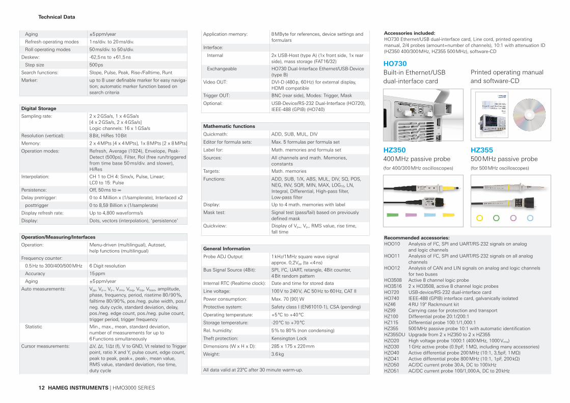
Technical Data
Technical Data
12 HAMEG INSTRUMENTS | HMO3000 SERIES
Accessories included: HO730 Ethernet/USB dual-interface card, Line cord, printed operating manual, 2/4 probes (amount=number of channels), 10:1 with attenuation ID (HZ350 400/300 MHz, HZ355 500 MHz), software-CD
HO730Built-in Ethernet/USB dual-interface card
Printed operating manual and software-CD
Recommended accessories:HOO10 Analysis of I2C, SPI and UART/RS-232 signals on analog
and logic channelsHOO11 Analysis of I2C, SPI and UART/RS-232 signals on all analog
channelsHOO12 Analysis of CAN and LIN signals on analog and logic channels
for two busesHO3508 Active 8 channel logic probeHO3516 2 x HO3508, active 8 channel logic probesHO720 USB-device/RS-232 dual-interface cardHO740 IEEE-488 (GPIB) interface card, galvanically isolatedHZ46 4 RU 19" Rackmount kitHZ99 Carrying case for protection and transportHZ100 Differential probe 20:1/200:1HZ115 Differential probe 100:1/1,000:1HZ355 500 MHz passive probe 10:1 with automatic identificationHZ355DU Upgrade from 2 x HZ350 to 2 x HZ355HZO20 High voltage probe 1000:1 (400 MHz, 1000 Vrms)HZO30 1 GHz active probe (0.9 pF, 1 MΩ, including many accessories)HZO40 Active differential probe 200 MHz (10:1, 3,5pF, 1 MΩ)HZO41 Active differential probe 800 MHz (10:1, 1pF, 200 kΩ)HZO50 AC/DC current probe 30 A, DC to 100 kHzHZO51 AC/DC current probe 100/1,000 A, DC to 20 kHz
HZ350400 MHz passive probe(for 400/300 MHz oscilloscopes)
HZ355500 MHz passive probe(for 500 MHz oscilloscopes)
Aging ±5 ppm/year
Refresh operating modes 1 ns/div. to 20 ms/div.
Roll operating modes 50 ms/div. to 50 s/div.
Deskew: -62,5 ns to +61,5 ns
Step size 500 ps
Search functions: Slope, Pulse, Peak, Rise-/Falltime, Runt
Marker: up to 8 user definable marker for easy naviga-tion; automatic marker function based on search criteria
Digital Storage
Sampling rate: 2 x 2 GSa/s, 1 x 4 GSa/s [4 x 2 GSa/s, 2 x 4 GSa/s] Logic channels: 16 x 1 GSa/s
Resolution (vertical): 8 Bit, HiRes 10 Bit
Memory: 2 x 4 MPts [4 x 4 MPts], 1x 8 MPts [2 x 8 MPts]
Operation modes: Refresh, Average (1024), Envelope, Peak- Detect (500ps), Filter, Rol (free run/triggered from time base 50 ms/div. and slower), HiRes
Interpolation: CH 1 to CH 4: Sinx/x, Pulse, Linear; LC0 to 15: Pulse
Persistence: Off, 50 ms to ∞
Delay pretrigger: 0 to 4 Million x (1/samplerate), Interlaced x2
posttrigger 0 to 8,59 Billion x (1/samplerate)
Display refresh rate: Up to 4,800 waveforms/s
Display: Dots, vectors (interpolation), ‘persistence’
Operation/Measuring/Interfaces
Operation: Menu-driven (multilingual), Autoset, help functions (multilingual)
Frequency counter:
0.5 Hz to 300/400/500 MHz 6 Digit resolution
Accuracy 15 ppm
Aging ±5 ppm/year
Auto measurements: Vpp, Vp+, Vp-, Vrms, Vavg, Vtop, Vbase, amplitude, phase, frequency, period, risetime 80 / 90 %, falltime 80 / 90 %, pos./neg. pulse width, pos./neg. duty cycle, standard deviation, delay, pos./neg. edge count, pos./neg. pulse count, trigger period, trigger frequency
Statistic Min., max., mean, standard deviation, number of measurements for up to 6 Functions simultaneously
Cursor measurements: ∆V, ∆t, 1/∆t (f), V to GND, Vt related to Trigger point, ratio X and Y, pulse count, edge count, peak to peak, peak+, peak-, mean value, RMS value, standard deviation, rise time, duty cycle
Application memory: 8 MByte for references, device settings and formulars
Interface:
Internal 2x USB-Host (type A) (1x front side, 1x rear side), mass storage (FAT16/32)
Exchangeable HO730 Dual-Interface Ethernet/USB-Device (type B)
Video OUT: DVI-D (480 p, 60 Hz) for external display, HDMI compatible
Trigger OUT: BNC (rear side), Modes: Trigger, Mask
Optional: USB-Device/RS-232 Dual-Interface (HO720), IEEE-488 (GPIB) (HO740)
Mathematic functions
Quickmath: ADD, SUB, MUL, DIV
Editor for formula sets: Max. 5 formulas per formula set
Label for: Math. memories and formula set
Sources: All channels and math. Memories, constants
Targets: Math. memories
Functions: ADD, SUB, 1/X, ABS, MUL, DIV, SQ, POS, NEG, INV, SQR, MIN, MAX, LOG10, LN, Integral, Differential, High-pass filter, Low-pass filter
Display: Up to 4 math. memories with label
Mask test: Signal test (pass/fail) based on previously defined mask
Quickview: Display of Vp+, Vp-, RMS value, rise time, fall time
General Information
Probe ADJ Output: 1 kHz/1MHz square wave signal approx. 0,2Vpp (ta <4 ns)
Bus Signal Source (4Bit): SPI, I2C, UART, retangle, 4Bit counter, 4 Bit random pattern
Internal RTC (Realtime clock): Date and time for stored data
Line voltage: 100 V to 240 V, AC 50 Hz to 60 Hz, CAT II
Power consumption: Max. 70 [90] W
Protective system: Safety class I (EN61010-1), CSA (pending)
Operating temperature: +5 °C to +40 °C
Storage temperature: -20 °C to +70 °C
Rel. humidity: 5 % to 80 % (non condensing)
Theft protection: Kensington Lock
Dimensions (W x H x D): 285 x 175 x 220 mm
Weight: 3.6 kg
All data valid at 23°C after 30 minute warm-up.
More information | www.hameg.com 13
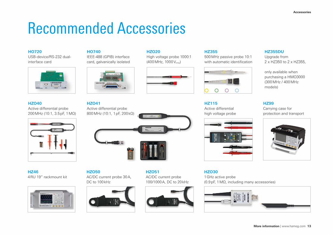
Recommended AccessoriesHO720USB-device/RS-232 dual-interface card
HZ99Carrying case for protection and transport
HZO20High voltage probe 1000:1 (400 MHz, 1000 Vrms)
HZO301 GHz active probe (0.9 pF, 1 MΩ, including many accessories)
HZO40Active differential probe 200 MHz (10:1, 3.5 pF, 1 MΩ)
HZO41Active differential probe 800 MHz (10:1, 1 pF, 200 kΩ)
HZO50AC/DC current probe 30 A, DC to 100 kHz
HZO51AC/DC current probe 100/1000 A, DC to 20 kHz
HZ115Active differential high voltage probe
HZ355500 MHz passive probe 10:1 with automatic identification
HZ355DUUpgrade from 2 x HZ350 to 2 x HZ355,
only available when purchasing a HMO3000 (300 MHz / 400 MHz models)
HO740IEEE-488 (GPIB) interface card, galvanically isolated
HZ464 RU 19” rackmount kit
Accessories
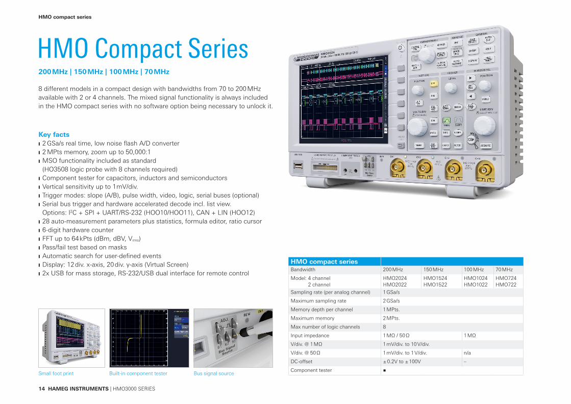
HMO compact seriesBandwidth 200 MHz 150 MHz 100 MHz 70 MHz
Model: 4 channel2 channel
HMO2024HMO2022
HMO1524HMO1522
HMO1024HMO1022
HMO724HMO722
Sampling rate (per analog channel) 1 GSa/s
Maximum sampling rate 2 GSa/s
Memory depth per channel 1 MPts.
Maximum memory 2 MPts.
Max number of logic channels 8
Input impedance 1 MΩ / 50 Ω 1 MΩ
V/div. @ 1 MΩ 1 mV/div. to 10 V/div.
V/div. @ 50 Ω 1 mV/div. to 1 V/div. n/a
DC-offset ± 0.2V to ± 100V –
Component tester
14 HAMEG INSTRUMENTS | HMO3000 SERIES
HMO Compact Series8 different models in a compact design with bandwidths from 70 to 200 MHz available with 2 or 4 channels. The mixed signal functionality is always included in the HMO compact series with no software option being necessary to unlock it.
Key facts 2 GSa/s real time, low noise fl ash A/D converter 2 MPts memory, zoom up to 50,000:1 MSO functionality included as standard (HO3508 logic probe with 8 channels required)
Component tester for capacitors, inductors and semiconductors Vertical sensitivity up to 1 mV/div. Trigger modes: slope (A/B), pulse width, video, logic, serial buses (optional) Serial bus trigger and hardware accelerated decode incl. list view. Options: I2C + SPI + UART/RS-232 (HOO10/HOO11), CAN + LIN (HOO12)
28 auto-measurement parameters plus statistics, formula editor, ratio cursor 6-digit hardware counter FFT up to 64 kPts (dBm, dBV, Vrms) Pass/fail test based on masks Automatic search for user-defi ned events Display: 12 div. x-axis, 20 div. y-axis (Virtual Screen) 2x USB for mass storage, RS-232/USB dual interface for remote control
200 MHz | 150 MHz | 100 MHz | 70 MHz
HMO compact series
Small foot print Bus signal sourceBuilt-in component tester
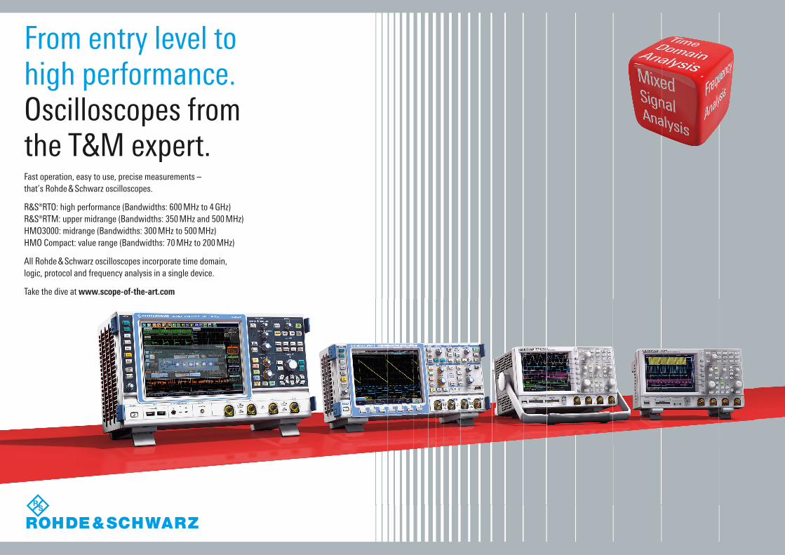
From entry level to high performance.Oscilloscopes from the T&M expert.Fast operation, easy to use, precise measurements – that’s Rohde & Schwarz oscilloscopes.
R&S®RTO: high performance (Bandwidths: 600 MHz to 4 GHz)R&S®RTM: upper midrange (Bandwidths: 350 MHz and 500 MHz)HMO3000: midrange (Bandwidths: 300 MHz to 500 MHz)HMO Compact: value range (Bandwidths: 70 MHz to 200 MHz)
All Rohde & Schwarz oscilloscopes incorporate time domain, logic, protocol and frequency analysis in a single device.
Take the dive at www.scope-of-the-art.com
value-instruments.com
HAMEG Instruments GmbH Industriestr. 6 | 63533 Mainhausen | Germany | Phone +49 (0) 6182 8000
www.hameg.com
R&S® is a registered trademark of Rohde & Schwarz GmbH & Co. KG HAMEG Instruments® is a registered trademark of HAMEG Instruments GmbH | Trade names are trademarks of the owners 11 / 2013 | © HAMEG Instruments GmbH | 4A-D000-0430 Printed in Germany | Subject to change without notice