mixerpac - flowserve · plants, diverse systems are ... the mixerpac 2564 features a liquid...
TRANSCRIPT

Flow Solutions Division
Mixerpac Standard wet lubricated mixer seals
According to DIN and special designs
Me c h a n i c a l s e a l s
f or
mi
xe
rs
,a
gi t a t o r s a n d r e a c t o r s

2
M i x e r p a c m i x e r s e a l s
Since the sixties mixer mechanical seals are successfullyused in mixer vessels of various construction and fulfill the required sealing tasks in the chemical, pharmaceutical and food industry as well as in the bioprocess engineering in a predominant number to themost complete satisfaction of the operaters. In processplants, diverse systems are employed for agitating,blending, kneading and drying products.
The units require low maintenance operation and safety,both, to protect the environment and the workplace.The mechanical seal design must provide excellent performance in the application, allowing for axial andradial shaft movements and shaft deflections.
We have the right solution to seal your machines safeand enomical. And we have a well-trained and motivated staff to support you. Nearby as well asworldwide.
Flowserve FSD is focused specifically to provide the bestmixer sealing solutions:• Liquid lubricated 256x range is a cost-effective
sealing solution• Modular design allows easy part replacement• Cartridge designs with and without a bearing (2561-2566)• Top and side mounted• Accommodation for sanitary gland/debris catcher for
applications requiring steam cleaning• Reverse-pressure capability and emergency sealing
solutions• Cooling flange option• Designs, engineered to fit major OEM’s• Designs, engineered according to DIN• Ability to handle significant radial and axial run-outs• Materials, selected for corrosion resistance and long
seal life• Split mixer seal designs to allow easy installation• Sterilizable designs available• Auxiliary systems, to enhance reliability• Knowledgeable and experienced mixer seal team
support• Ability, to design to customer specification
The whole range of seals for mixers, agitators, stirrers, kneaders, dryers, filters

3
M i x e r p a c m i x e r s e a l s
Mixer drive• Overview DIN 28 130 part 3 • Explanations appendix 1 to
DIN 28 130 part 3 • Demands DIN 28 161 Mixer vessel with mixer description DIN 28 130
DIN - Mixer drives
Overview liquid-lubricated mixer seals
Product Features
Type Page Standard Lubrication Flange Connections to DIN: Bearing Pmax in Remarks
Cartridge Shaft, Flange, Seal the vessel
Single&Double [bar]
2560 6 Cart Dbl wet glass-lined DIN 28 159 DIN 28 137 part 2 Bearing 6 Top entry
DIN 28138 part 2+3
2561 4 Cart Sgl wet stainless steel 6 Top entry
2562 4 Cart Sgl wet stainless steel Bearing 6 Top entry
2563 5 Cart Dbl wet stainless steel DIN 28 154 16 Top entry
2564 5 Cart Dbl wet stainless steel DIN 28 138 part 1+3 Bearing 16 Top entry
2565 5 Cart Dbl wet stainless steel DIN 28 141 6 Top entry, easy to clean
2566 5 Cart Dbl wet stainless steel Bearing 6 Top entry, easy to clean
577 9 Cart Dbl wet Bearing Top entry,
sterile
580 7 Cart Dbl wet Bearing 40 High pressure
581 7 Cart Dbl wet Bearing 250 High pressure
585 8 Cart Dbl wet Upon request 6 Bio reactors
586 8 Cart Dbl wet Bearing 6 Bio reactors
587 8 Cart Dbl wet 10 Side entry
588 8 Cart Dbl wet Bearing 10 Side entry
MIX
ERPA
C 2
560-
2566
acco
rdin
g t
o D
INSe
mi s
tand
ard
/Cus
tom
desi
gned
MIX
ERPA
C
Accessories 9
Auxiliaries 11
For Flowserve Mixerpac M-series (wet and dry running) please see separate brochure.
*) currently as draft
Driver pedestal formechanical seal
DIN 28 162 part 1
enamelled steel
Shaft end for mechanicalseal DIN 28 154
Shaft end steel, enamelled DIN 28 159 strength, appendix 1 to DIN 28 159 Mixer type
DIN 28 131
Mixer vessel DIN 28 136 part 1 and part 2
Mixer vessel DIN 28 136 part 1 and part 3*)
Mixer flange DIN 28 137
part 1
Mixer flange DIN 28 137
part 2
Assembly flange DIN 28 141
intermediate bearing
without integratedbearing
mild (carbon) steel and stainless steel
Coupling
Mechanical seal DIN 28 138 part 1
and part 3
Mechanical seal DIN 28 138 part 2and part 3

4
M i x e r p a c 2 5 6 1 - 2 5 6 2Liquid lubricated, top entry according to DIN
Cost-efficient liquid lubricated mixer mechanical seal,for low duties. These seals serie 256x is based on the DIN standard.They are equipped with standard parts for liquid lubricated seals. One housing for all varieties. Available as single (2561/62) and as double seal(2563/64), with bearing (2562/64) or without bearing(2561/2563).The Mixerpac 2564 features a liquid lubricated doubleseal and a bearing, it is designed for steel vessels.The Mixerpac 2560 is equipped with a glass-linedflange. The Mixerpac 2565, 2566 is designed for easy-to-clean applications.
Reverse-pressure capability.Left: Seal closed by barrier fluid Right: Seal closed by vessel-side pressure
Mixerpac 2561 single seal without bearing
Mixerpac 2562 single seal
with bearing
Operating parameters 2561-2564Pressure: Vacuum to 16 bar (in the vessel) • 2563, 2564 shaft size up to 100 mm
Vacuum to 10 bar • 2563, 2564 shaft size > 100 mm
Vacuum to 6 bar• 2561, 2562
quenched sealsTemperature: Double seals (in the vessel) • -20 to +200°C
• up to 300°C with cooling flange 810
Single seals• -20 to +150°C • up to 250°C with cooling
flange 810 Linear face speed: 4 m/s (Double seals)
2 m/s (Single seals)Shaft sizes (d3): 40 to 220 mm
H H
D
G
G
FE
C
B
A
Supply Connections according to DIN 28 138 part 3
A Barrier liquid inletB Barrier liquid outletC Leakage control
atmospheric sideD Leakage control
product sideE Cooling inletF Cooling outletG Grease
Materials 2561-2566Seal faces: Resin-impregnated carbon / Silicon
carbideSilicon carbide / Silicon carbide (optional)
Metal parts: Product-wetted: 1.4571 (~ 316 TI stainless steel)
Non product wetted: 1.4122 (~AISI 431)
Gaskets: Elastomers, Non-elastomers, PTFE

5
M i x e r p a c 2 5 6 3 - 2 5 6 6For steel vessels, cost efficient design
Mixerpac 2563 double seal without bearing
Mixerpac 2564 double seal
with bearing
d3 d7 d1 nxd2 d4 d8 d9 d10 d20 a h1 h2 k l1 l2 A,B C40 38 175 4x18 110 91 102,5 M12 M16 130 193 131 145 16 30 G3/8 G1/850 48 240 8x18 176 105.5 119 M12 M16 153 214,5 140 210 18 30 G3/8 G1/860 58 240 8x18 176 115.5 129 M12 M16 163 222 150 210 18 30 G3/8 G1/880 78 275 8x22 204 145 161 M16 M20 200 250 160 240 20 35 G1/2 G1/8100 98 305 8x22 234 170 188 M16 M20 218 268 170 270 20 35 G1/2 G1/8125 120 330 8x22 260 195 211 M20 M20 248 289,5 192,5 295 22 40 G1/2 G1/8140 135 395 12x22 313 212 228 M20 M20 285 305 199 350 22 40 G1/2 G1/8160 150 395 12x22 313 232 250 M20 M20 342 323 205 350 25 42 G1/2 G1/8180 170 445 12x22 364 258 276 M24 M20 372 345,5 221 400 25 45 G1/2 G1/8200 190 445 12x22 364 280 296 M24 M20 360 326,5 225 400 28 45 G1/2 G1/8220 210 505 16x22 422 300 316 M24 M20 415 377 234,5 460 28 50 G1/2 G1/8
Dimensional data Mixerpac 2561-2566
Features 2560-2566• Modular construction Mixperpac 2560 to 2566 • Cartridge design• Reverse pressure capability of the product side seal
(Mixerpac 2560 - 2564)• Pressure-tested unit with integrated self-aligning
roller bearing (movable bearing) - Mixerpac 2562, 2564, 2566
• Fully equipped with PTFE gaskets (optional)• Bi-directional rotation• Barrier circulation bi-directional by baffle• Connections according to DIN• Torque transmission by means of a shrink disc
Mixerpac 2565double sealwithout bearing
Mixerpac 2566double seal
with bearing
Mixerpac 2565, 2566 for vessels ofcarbon steel and stainless steel
Features 2565-2566• Easy-to-clean design• Modular construction: interchangeable with
series 2561 - 2564• Cartridge design• Pressure-tested unit with integrated self-aligning
roller bearing (movable bearing)• Fully equipped with PTFE gaskets (optional)• Bi-directional rotation• Barrier circulation bi-directional by baffle• Connections according to DIN• Torque transmission by means of a shrink disc
Operating parameters 2565-2566Pressure: Vacuum to 6 bar (in the vessel)Temperature: -20 to +150°C(in the vessel)Linear face speed: 4 m/s Shaft sizes (d3): 40 to 220 mm

6
M i x e r p a c 2 5 6 0For glass lined vessels, according to DIN
Double seal with bearing, glass-lined flange Flange connection to DIN 28 138 part 2 for nominal sizesof 40 to 100
Features 2560• Modular construction • Cartridge design w/o flange • Can be dis-/mounted as cartridge, without
glass-lined flange • Reverse pressure capability• Fully equipped with PTFE gaskets (optional)• Pressure-tested unit with integrated self-aligning
roller bearing (movable bearing) • Connections according to DIN• Torque transmission by means of a shrink disc
Operating parameters 2560Pressure: Vacuum to 6 bar (in the vessel)Temperature: -25 to +200°C (in the vessel)Linear face speed: 4 m/s Shaft sizes (d3): 40 to 160 mm
Materials 2560Seal faces: Resin-impregnated carbon / Silicon
carbideMetal parts: Product-wetted:
glass-linedNon product wetted:
1.4122 (~AISI 431)Gaskets: Elastomers, Non-elastomers, PTFE
Flange connections to DIN 28 138 T 2sizes 125 to 161
Dimensional data Mixerpac 2560
d31) d7
1) Nominal Flange d1 n x d2 d4 n x d5 d6 d7 M1 M2 a h k1 k2 l1 l2 A, B Csize size2)
40 38 40 E 125 175 4x18 110 - - 102 M12 M16 110 213 145 - 20 28 G3/8 G1/850 48 50 E 200 240 8x18 176 - - 138 M12 M16 140 240 210 - 20 28 G3/8 G1/860 58 60 E 250 275 8x22 204 - - 188 M12 M16 150 250 240 - 22 30 G3/8 G1/880 78 80 E 300 305 8x22 234 - - 212 M16 M20 190 279 270 - 22 35 G1/2 G1/8100 98 100 E 400 395 12x22 313 - - 268 M16 M20 200 308 350 - 25 35 G1/2 G1/8100 98 100 E 500 395 12x22 313 - - 268 M16 M20 200 308 350 - 25 35 G1/2 G1/8125 120 125 E 700 505 4x22 422 12x22 320 306 M20 M20 250 333 460 350 28 40 G1/2 G1/8140 135 140 E 700 505 4x22 422 12x22 320 306 M20 M20 265 359 460 350 30 40 G1/2 G1/8160 150 160 E 700 505 4x22 422 12x22 320 306 M16 M20 305 384 460 350 30 40 G1/2 G1/8160 150 160 E 900 505 4x22 422 12x22 320 306 M16 M20 305 384 460 350 30 40 G1/2 G1/8160 150 161 E 901 565 4x26 474 12x22 370 356 M16 M20 305 384 515 400 30 40 G1/2 G1/8
Measures in mm - 1) Shaftdiameter d3 and d7 according to DIN 28 159 2) Flange size according to DIN 28 137 part 2

7
M i x e r p a c 5 8 0 - 5 8 1For medium/high pressure applications
Mixerpac 580 Features 580Mechanical seals for medium pressure mixer vesselsand reactors.• Top entry• Bi-directional • Integrated self aligning spherical roller bearing as
movable bearing configuration • Fully equipped with PTFE gaskets (optional)• Basic seal FEM (Finite-Element-Method) analysed
Materials 580-581Seal faces 580: Resin-impregnated carbon / Silicon
carbideSilicon carbide / Silicon carbide (optional)
Seal faces 581: Silicon carbide / Resin-impregnated carbon
Metal parts: 1.4571 (~ 316 TI stainless steel)Gaskets: Elastomers, Non-elastomers, PTFE
Mixerpac 581
Dimensional data Mixerpac 580
Adaptive parts for 581 designed to seal chamberand machine dimensions
d3 d1 nxd2 d4 d8 d9 d20 h k l1 l2 A, B C, D
30 198 4x22 121 44 54 M16 212 160 50 26 G3/8 G1/8
40 198 4x22 121 52 64.5 M16 220 160 50 26 G3/8 G1/8
50 248 8x22 176 73.5 85.5 M16 248 210 55 30 G3/8 G1/8
60 248 8x22 176 83.5 95.5 M20 248 210 55 30 G3/8 G1/8
70 248 8x22 176 92 105.5 M20 260 210 55 38 G1/2 G1/8
80 285 8x26 204 107 121.5 M20 290 240 60 38 G1/2 G1/8
90 285 8x26 204 127.5 141.5 M20 300 240 60 38 G1/2 G1/8
100 320 8x30 234 138 153.5 M20 310 270 65 38 G1/2 G1/8
110 320 8x30 234 138 153.5 M20 325 270 65 45 G1/2 G1/8
120 345 8x30 260 162 178 M20 330 295 70 45 G1/2 G1/8
125 345 8x30 260 162 178 M20 348 295 70 45 G1/2 G1/8
130 345 8x30 260 162 178 M20 348 295 70 45 G1/2 G1/8
140 400 12x30 313 188 203.5 M20 355 350 75 45 G1/2 G1/8
150 400 12x30 313 188 203.5 M20 368 350 75 45 G1/2 G1/8
160 400 12x30 313 188 203.5 M20 375 350 75 45 G1/2 G1/8
170 400 12x30 313 225 240.5 M20 380 350 75 45 G1/2 G1/8
180 460 12x33 364 225 240.5 M20 398 400 80 50 G1/2 G1/8
190 460 12x33 364 238 253.5 M20 405 400 80 50 G1/2 G1/8
200 460 12x33 364 238 253.5 M20 410 400 80 50 G1/2 G1/8
210 520 16x33 422 264 279.5 M20 415 460 90 50 G1/2 G1/8
220 520 16x33 422 264 279.5 M20 415 460 90 50 G1/2 G1/8
Features 581Mechanical seals for high pressure mixer vessels andreactors.• Hydraulically balanced mating rings• Deformation resistant faces• Fully equipped with PTFE gaskets (optional)• Basic seal FEM (Finite-Element-Method) analysed
Operating parameters 580-581580 581
Pressure: Vacuum to 40 bar Vacuum to 250 bar(in the vessel)Temperature: -20 to +200°C -80 to +200°C(in the vessel) up to 300°C with cooling flangeLinear face speed: 4 m/sShaft sizes (d3): 20 to 220 mm; other sizes upon
request

8
M i x e r p a c 5 8 5 - 5 8 8For top/bottom/side entry
Mixerpac 585without bearing
Mixerpac 586with bearing
Mixerpac 587without bearing
Mixerpac 588with bearing
Features 585-586Mechanical seals for bioreactors and others.• Bottom entry• Bi-directional• Integrated self aligning spherical roller bearing as
movable bearing configuration• Rotating spring-loaded unit, including
self-emptying features• Guiding bushing provides proper barrier liquid
circulation also to the product side faces for sufficient heat dissipation
• Construction with few gaps and crevices
Features 587-588• Side entry, top entry• Mechanical seals for high viscous or pulverized
products• Guiding bushing provides proper barrier liquid
circulation also to the product side faces for sufficient heat dissipation
• Construction with few gaps and crevices
Operating parameters 585-588Pressure: Vacuum to 6 bar (585, 586) (in the vessel) Vacuum to 10 bar (587, 588)(balanced seal) Higher pressures upon requestTemperature: -20 to +180°C (585, 586)(in the vessel) -20 to +200°C (587, 588)Linear face speed: 4 m/s (585, 586), 10 m/s (587, 588) Shaft sizes (d3): 40 to 220 mm (585, 586); other sizes
40 to 200 mm (587, 588); upon request
Materials 585-588Seal faces: Silicon carbide / Resin or antimony
impregnated carbonSilicon carbide / Silicon carbideTungsten carbide / Tungsten carbide (587, 588)
Metal parts: 1.4571 (~ 316 TI stainless steel)Gaskets: Elastomers, Non-elastomers, PTFE
Dimensional data Mixerpac 585-588
Adaptive parts designed to seal chamber and machine dimensions
d3 d2 d1 d4 d5 d6 d7 d8 k n l1 l2 l3 l4 l5 l6 A,B C40 80 130 150 190 11 85 100 170 8 42 170 210 22 158 200 G3/8 G1/850 100 150 170 225 11 105 120 195 8 42 180 240 55 168 228 G3/8 G1/860 120 160 190 245 11 125 140 205 8 45 190 250 60 175 235 G3/8 G1/880 150 220 240 300 14 160 180 250 8 48 210 270 65 195 225 G1/2 G1/4100 170 240 260 320 14 180 200 270 8 48 230 300 65 215 285 G1/2 G1/4110 190 250 270 330 14 200 220 280 8 52 240 320 70 225 300 G1/2 G1/4125 205 265 295 385 18 215 235 330 8 52 250 330 70 232 310 91/2 G1/4140 230 290 310 400 18 240 260 345 8 55 255 350 75 235 330 91/2 G1/4160 245 300 320 410 18 260 280 355 8 60 260 360 80 240 340 91/2 G1/4180 255 320 345 430 18 270 300 375 12 60 270 370 80 250 350 91/2 G1/4200 270 350 360 440 18 285 320 395 12 65 290 410 90 265 385 91/2 G1/4

9
M i x e r p a c 5 7 7 a n d a c c e s s o r i e s
Cleaning-Sterilization• Methods:
• CIP = Cleaning in Place, i.e. the installed mechanical seals are cleaned with a washing solution of 2% nitric acid and flushed with a 5% caustic soda lye (upto pH = 14). This is done at a temperature of t = 60°C to 80°C over a period of approx. 15 minutes.
• SIP = Sterilization in Place, i.e. the installed mechanicalseals are sterilized at stationary shaft with steam at about 135°C and a pressure of p = 3,5 to 4 bar for a period of approx. 30 minutes.
• Frequently used terms related to sterilization:• FDA = Food and Drug Administration, Division of the
US Department of Health, Education and Welfare. Supervises food, drug and cosmetics to the protectionof the population.
• GMP = Good Manufacturing Practices. Basic principlesfor the production and quality control of drugs published for the first time in 1968 by the World Health Organization.
• QHD = Qualified Hygienic Design. Guidelines for sterilization from VDMA.
Requirements on mixer mechanical seals• Construction with few gaps and crevices • Good possibility to clean/sterilize• Non-abrasive materials for faces and gaskets• Smooth, rounded surface contour on the product side• High surface quality of the product touched parts
(Ra < 0,8 µm)• Good resistance against steam, hot water, disinfectant
also with CIP• Non-poisonous materials, being non-ageing and
non-corroding, colorless and tasteless, light and ozone resistant.
Mixerpac 577Sterile design
Custom designed mixer seals for sterile applications.
Cooling flange 810 for Mixerpac 2561, 2562, 2563, 2564
Operating parameters 810Pressure: 16 bar Temperature: 300°C Double seals
250°C Single sealsCooling flanges for other seals upon request
Dimensional data 810
d3 d1 nxd2 d4 d8 d9 d20 h1 k40 175 4x18 110 91 105 M16 58 14550 240 8x18 176 106 121 M16 58 21060 240 8x18 176 116 131 M16 58 21080 275 8x22 204 145 163 M20 60 240
100 305 8x22 234 170 188 M20 65 270125 330 8x22 260 195 213 M20 65 295140 395 12x22 313 212 230 M20 65 350160 395 12x22 313 232 250 M20 75 350180 445 12x22 364 258 276 M20 75 400200 445 12x22 364 280 298 M20 75 400220 505 16x22 422 300 318 M20 75 460
Optional with/without leakage cup
Leakage cup (optional)
The leakage cup drains the leakage.
For sterile applications

10
A c c e s s o r i e sComponents
Demands on barrier liquids
Barrier liquids must be clean, free from solid
particles, of low viscosity, be product
compatible, temperature resistant and must
not attack materials in use. Water and oils
are most frequently used as barrier liquid.
The following must be adhered to:
Water: On account of its good heat
conductivity water is very suitable as a
barrier.
The high solubility of salts and gases in
water however, proves detrimental.
Frequently the deposition of salts and other
solid particles at hot surfaces e.g. in sealing
gaps, is the result.
In order to avoid this a prepared, softened
or distilled water or condensate is preferred.
An antifreeze without additives like e.g.
glycols may be added if freezing risk is
given.
Oil: Useful is mineral oil or synthetic oil
with a viscosity of 15 to max. 50 mm2/s (cSt)
at working temperature. In addition the oil
must be resistant to aging and, even in
contact with the product, not tend to paste
or coke.
Clamping devices for securing the seal on the shaft
Torque transmission by means of a shrink disc
Torque transmissionby means of a clamping-ring unit
Torque transmission bymeans of a split clamping-ring unit
Stand-still seals
Stand-still seal Emergency seal
Shaft in rotation Shaft is stopped
InstallationTolerance check before fitting the Mixerpac seal
d acc. to DIN 28 144, DIN 28 154 and DIN 28 159
d (mm)40 50 60 80 100 125 140160 180 200 220
permissible 1 0,15 0,20 0,25tolerances 2 0,20 0,25 0,30
3 0,10 0,20 0,30
Possibility to change the seal withthe vessel loaded
Not activated during shaft rotation;activated during stand-still
3
d
1 2
25
0.8
6.3
0.8
flange
shaft

9
21
O
BB
7
PI
L
11
19
FI
12
10
1
14
1316
17
2
5
43
8
6
V
B
A
T
L KM
H
J
TI
GLRD
15
Cu
sto
mer
co
nd
ensa
tesy
stem
Piping schematic, unpressurized system, optional with heat exchanger
Piping schematic, pressurized system, with heat exchanger, optional with forced circulation
1 Vessel (pressureless)2 Cooling coil3 Drain4 Level indicator
5 Level switch6 Thermometer7 Orifice to the vent8 Filling connection
1 Vessel2 Cooling coil3 Drain4 Level indicator5 Level switch6 Thermometer
7 Vent8 N2-connection9 Pressure gauge
10 Filling pump11 Refill vessel
1 Reservoir2 Level gauge with
temperature indicator
3 Motor4 Gear pump5 Safety relief valve6 Non return valve7 Pressure indicator8 Accumulator9 Temperature
indicator10 Non return valve
11 Flowmeter12 Filter with
bypass valve13 Filler breather filter14 Heat exchanger15 Pressure control
valve16 Level switch17 Valve19 Identification plate
Piping schematic, pressurized system, with heat exchanger, optional with forced circulation
1 Vessel2 Pressure indicator3 Level gauge 4 Temperature
indicator5 Valve6 Vent valve7 Heat exchanger
8 Steam exhaust valve
9 Valve10 Steam supply valve11 Condensate valve12 Condensate
separator
Sealant systems for sterile applications
Steam supply
11
Complete sealant systems
A u x i l i a r i e s
Quench fluid tankCapacity 3l
Pressure 0 bar
Temperature up to 200°C
Thermosyphon pressure vesselCapacity 6l 10l
Pressure
standard 32 bar 20 bar
optional 40, 64bar 40, 64 bar
Temperature up to 200°C
Consumption
capacity 1.8l 3.8l
Pressure transmitterCapacity 3l 6l
optional 15l
Pressure
standard 40 bar 32 bar
optional 64 bar 40, 64 bar
Temperature up to 150 °C
Consumption
capacity 0.8l 1.3l
Cooling capacity at:
Thermosyphon
circulation 1 kw 1.5 kw
Forced
circulation 2.5 kw 4 kw
Pressurizer with gear pump and self-acting pressure resistance, when motor failsPumpcapacity 6l/min 12l/min
Sealant pressure 10 to 50 bar
Oil viscosity at 50°C 12mm2/s 90mm2/s
Tankcapacity 40l 70l
Dimensions:
height 780mm 810mm
width 700mm 800mm
depth 440mm 505mm
© 1995 EURRev 05/00 EURFSD 127
www.flowserve.com
Flow Solutions DivisionBW SealsDurametallic Seals Pacific Wietz SealsPac-Seal
Service• Service Centers near-by to you• Service Centers wordwide• Repair of all mixer seals• Full range of seals for mixers
Products• Standard seals • Standard seals according to DIN • Sterile design• Custom engineered by using
standard parts• Custom engineered
Support• Consulting by our engineers
near-by to you• Consulting by our mixer support
group in our facilities in Dortmund and Kalamazoo
• Global engineering capacity • Experience since 1919
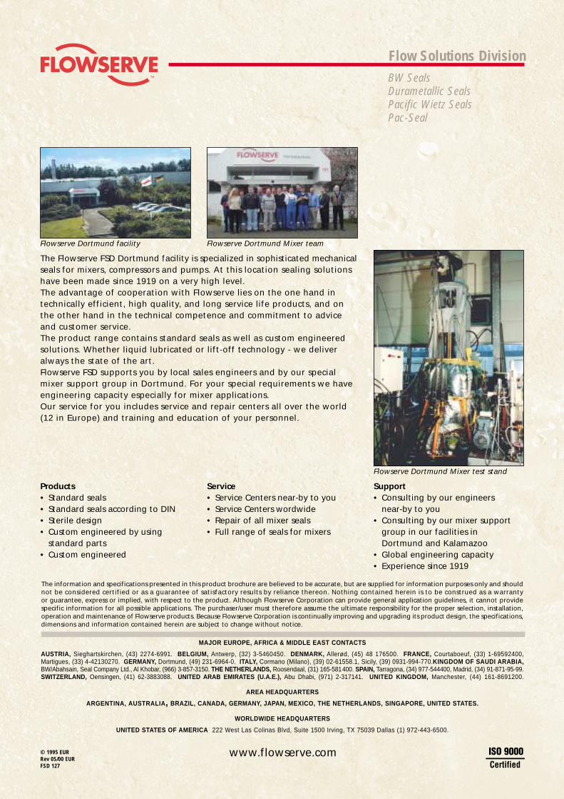
The Flowserve FSD Dortmund facility is specialized in sophisticated mechanicalseals for mixers, compressors and pumps. At this location sealing solutionshave been made since 1919 on a very high level.The advantage of cooperation with Flowserve lies on the one hand in technically efficient, high quality, and long service life products, and onthe other hand in the technical competence and commitment to adviceand customer service.The product range contains standard seals as well as custom engineeredsolutions. Whether liquid lubricated or lift-off technology - we deliveralways the state of the art.Flowserve FSD supports you by local sales engineers and by our specialmixer support group in Dortmund. For your special requirements we haveengineering capacity especially for mixer applications.Our service for you includes service and repair centers all over the world(12 in Europe) and training and education of your personnel.
The information and specifications presented in this product brochure are believed to be accurate, but are supplied for information purposes only and shouldnot be considered certified or as a guarantee of satisfactory results by reliance thereon. Nothing contained herein is to be construed as a warrantyor guarantee, express or implied, with respect to the product. Although Flowserve Corporation can provide general application guidelines, it cannot providespecific information for all possible applications. The purchaser/user must therefore assume the ultimate responsibility for the proper selection, installation,operation and maintenance of Flowserve products. Because Flowserve Corporation is continually improving and upgrading its product design, the specifications,dimensions and information contained herein are subject to change without notice.
Flowserve Dortmund facility Flowserve Dortmund Mixer team
Flowserve Dortmund Mixer test stand
MAJOR EUROPE, AFRICA & MIDDLE EAST CONTACTS
AUSTRIA, Sieghartskirchen, (43) 2274-6991. BELGIUM, Antwerp, (32) 3-5460450. DENMARK, Allerød, (45) 48 176500. FRANCE, Courtaboeuf, (33) 1-69592400,Martigues, (33) 4-42130270. GERMANY, Dortmund, (49) 231-6964-0. ITALY, Cormano (Milano), (39) 02-61558.1, Sicily, (39) 0931-994-770.KINGDOM OF SAUDI ARABIA,BW/Abahsain, Seal Company Ltd., Al Khobar, (966) 3-857-3150. THE NETHERLANDS, Roosendaal, (31) 165-581400. SPAIN, Tarragona, (34) 977-544400, Madrid, (34) 91-871-95-99.SWITZERLAND, Oensingen, (41) 62-3883088. UNITED ARAB EMIRATES (U.A.E.), Abu Dhabi, (971) 2-317141. UNITED KINGDOM, Manchester, (44) 161-8691200.
AREA HEADQUARTERS
ARGENTINA, AUSTRALIA, BRAZIL, CANADA, GERMANY, JAPAN, MEXICO, THE NETHERLANDS, SINGAPORE, UNITED STATES.
WORLDWIDE HEADQUARTERS
UNITED STATES OF AMERICA 222 West Las Colinas Blvd, Suite 1500 Irving, TX 75039 Dallas (1) 972-443-6500.