mk-7 maintenance manual revision3 - barudan …barudanamerica.com/assets/files/mk-7 maintenance...
TRANSCRIPT
MK-7 Maintenance Manual Ver.20120809R02
Page 1
MK-7 Maintenance Manual Revision3
(Ver.20120809R02)
1. Features ------------------------------------------------------------------------------------ P2 2. Components ------------------------------------------------------------------------------- P2-P3 3. How to replace the fixed knife and drive knife --------------------------------------- P4-P7 4. How to adjust the pressure of the knives --------------------------------------------- P8-P9 5. How to adjust the thread dividing hook ----------------------------------------------- P10-P12 6. How to adjust the positioning finger --------------------------------------------------- P12 7. Trimmer troubleshooting and adjustments ------------------------------------------- P13-P15 8. Parameter List ----------------------------------------------------------------------------- P16-P17

MK-7 Maintenance Manual Ver.20120809R02
Page 2
1. Features
The drive knife doesn’t extend out from the front edge of the needle plate. Therefore caps and other garments are not damaged by the protruding knives.
The embroidery field on Caps near the crown of the cap is better, because the MK-7 needle
plate is shorter. The MK-5 required a longer needle plate or an added trimmer guard.
The MK-7 trimmer is faster than the MK-5 due to the MK-5 having to make an intermediate stop before a trim is completed.
The MK-7 fixed knife and the drive knife are mounted separately. So replacing MK-7 knives is
easier than the MK-5.
The MK-7 knife durability is better than the MK-5.
2. Components
Cylinder bed, etc.
No. QJ210031
Part Lower thread knife drive rod
No. QJ210050
Part Cylinder bed cover for MK-7
No. NB0QJ210060
Part Cylinder bed cover for MK7-T
No. QJ210010 Part Needle plate base MK7-T
No. QJ270001 Part Needle plate Assy MK7-T

MK-7 Maintenance Manual Ver.20120809R02
Page 3
No. QJ270001
Part Needle plate ASSY MK7-T
No. QJ270011
Part Cylinder needle plate MK7-T
No. QJ270020 Part Drive knife MK7-T
No. QJ270040
Part Drive knife rotating shaft MK-T
No. QJ270060 Part Metal washer MK7-T
No. KX270010
Part Fixed knife fixing screw
No. QJ270070
Part 3.2x5x0.5 Washer
No. QJ270080 Part M3x2 Hex socket set screw (Black, w/glue)
No. QJ270030
Part Fixed knife MK7-T
No. QJ270090
Part Bobbin thread keep stay ASSY MK7-T
Needle plate Assy
No. QJ270140 Part Wave washer MK7-T
Needle plate base
No. KX270430
Part Positioning finger screw for cylinder
No. QJ210010
Part Needle plate base MK7-T
No. SJ210171 Part Positioning finger for cylinder(BA)
No. HS210300
Part Thread dividing hook (Cylinder MK5)
No. KC271001
Part Upper knife rotating shaft
No. HS210051
Part Thread dividing hook fixing stay (short type)
MK-7 Maintenance Manual Ver.20120809R02
Page 4
3. How to replace the fixed knife and the drive knife
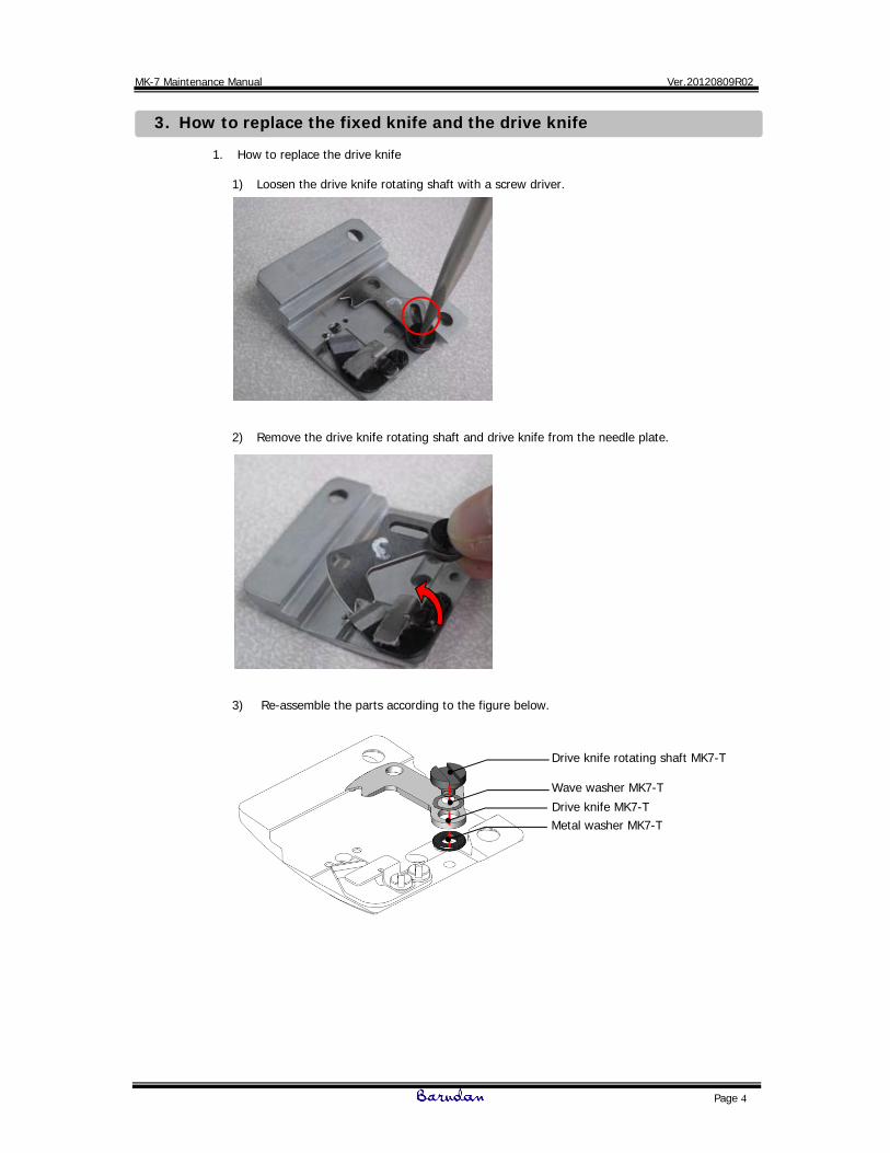
1. How to replace the drive knife
1) Loosen the drive knife rotating shaft with a screw driver.
2) Remove the drive knife rotating shaft and drive knife from the needle plate.
3) Re-assemble the parts according to the figure below.
Drive knife rotating shaft MK7-T
Wave washer MK7-T
Drive knife MK7-T Metal washer MK7-T

MK-7 Maintenance Manual Ver.20120809R02
Page 5
4) After assembling the drive knife and related parts, check the setting of the drive knife and fixed knife with the following procedure;
* If the knives do not cut properly, you’ll need to change the fixed knife pressure.
Please refer to “4. How to adjust the pressure of the knives”.
Please move the drive knife sideways by pushing the back edge of the moving knife, parallel with the needle plate. If you move the drive knife by pressing downward, the cutting action is not being tested accurately because there is extra pressure being applied to the drive knife towards the fixed knife, than what’s normal.
(2) Hook the thread on the v-notch of the drive knife.
(3) Push the drive knife to the cut position. Please pay attention not to push down on the knife with your fingertip.
(4) Cut the thread. Don’t put tension on the thread. The thread must be loose.
(1) Insert a piece of thread into the needle hole
Trimming point

MK-7 Maintenance Manual Ver.20120809R02
Page 6
2. How to replace the fixed knife
1) Loosen the (2) mounting screws for the fixed knife using a screwdriver.
2) Remove the screws and fixed knife from the needle plate.
3) Re-assemble the parts according to the figure below.
Counter knife fixing screw
Washer 3.2x5x0.5
Lower thread keep stay assy MK7-T
Counter knife MK7-T

MK-7 Maintenance Manual Ver.20120809R02
Page 7
Driving pin
After mounting the fixed knife and related parts, cut the thread manually and check how well the knives cut. Please refer to procedure on Page 5.
3. Special attention. Mounting the needle plate to the needle plate base.
* If the knives do not cut properly, you’ll need to change the knife pressure. Please refer to “4. How to adjust the pressure of the knives”.
Please pay attention to the following points when you install the fixed knife.
1. Push the fixed knife in direction 1, and lightly in direction 2 and tighten screw A for the fixed knife. The edge of the fixed knife must be parallel with the edge of the needle plate, as shown.
2. Please check that the thread keep stay assembly is not tilted. It should be parallel with the needle plate. If OK, tighten screw B for the fixed knife.
A
B
1 2
The driving pin of the lower thread knife driving rod must be set into the groove of the drive knife properly. If they are not set properly, the drive knife may be damaged.

MK-7 Maintenance Manual Ver.20120809R02
Page 8
4. How to adjust the pressure of the knives
1. The following symptoms may be caused by improper pressure of the knives; The thread is not cut. Cut tail end of the thread after trimming is fuzzy (not cut cleanly).
Please adjust the pressure of the knives according to the following procedure.
1) Loosen the (2) fixed knife mounting screws with a screwdriver (* A).
2) By tightening the M3x2 hex socket set screw, the fixed knife’s angle changes and the pressure between the fixed and drive knives increases.
1
Before adjustment
After adjustment
* A
MK-7 Maintenance Manual Ver.20120809R02
Page 9
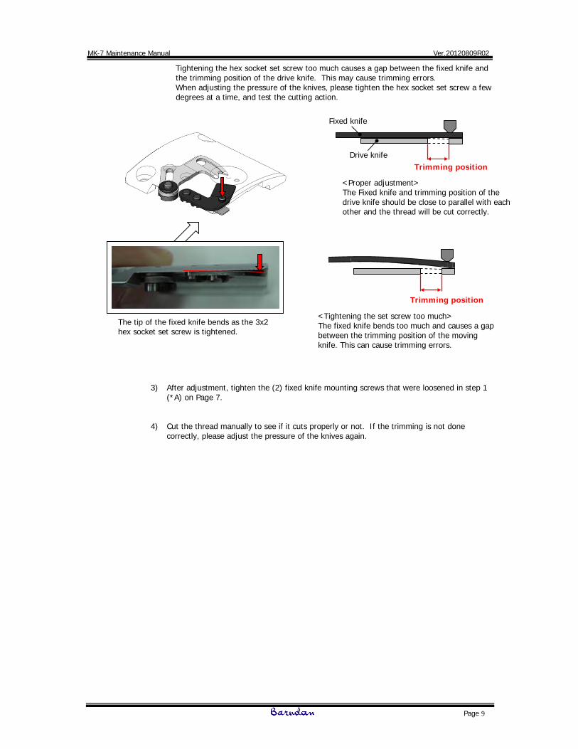
Tightening the hex socket set screw too much causes a gap between the fixed knife and the trimming position of the drive knife. This may cause trimming errors. When adjusting the pressure of the knives, please tighten the hex socket set screw a few degrees at a time, and test the cutting action.
3) After adjustment, tighten the (2) fixed knife mounting screws that were loosened in step 1
(*A) on Page 7.
4) Cut the thread manually to see if it cuts properly or not. If the trimming is not done correctly, please adjust the pressure of the knives again.
Trimming position
<Proper adjustment> The Fixed knife and trimming position of the drive knife should be close to parallel with each other and the thread will be cut correctly.
The tip of the fixed knife bends as the 3x2 hex socket set screw is tightened.
Fixed knife
Trimming position
<Tightening the set screw too much> The fixed knife bends too much and causes a gap between the trimming position of the moving knife. This can cause trimming errors.
Drive knife

MK-7 Maintenance Manual Ver.20120809R02
Page 10
5. How to adjust the thread dividing hook (trimmer fork)
1. Please adjust the standby position of the thread dividing hook for MK-7 according to the following procedure.
1) Loosen the M3x5 hex socket bolt to allow the hook driving rod to move freely.
2) Move the hook driving rod back and forth to allow a gap between the thread dividing hook
and the cylinder bed cover to be 0 ~ 0.5 mm.
M3x5 Hex socket bolt
0~0.5mm
Solenoid lever in standby position
No. KC271940C Part Solenoid lever A
No. KN272401 Part Eccentric stopper assy
No. BJ210040 Part Solenoid stay MK7-T
M3x5 Hex socket bolt
No. HS210070 Part Hook driving rod

MK-7 Maintenance Manual Ver.20120809R02
Page 11
3) After that, tighten the M3x5 hex socket bolt to lock the hook driving rod in place.
2. Please adjust the engaged position of the thread dividing hook of MK-7 according to the following procedure.
1) Loosen the M4x18 hex socket bolt for the eccentric stopper.
2) Turn the eccentric stopper assy to adjust the engaged position.
The gap between the bobbin and thread dividing hook should be 0.7mm when the solenoid lever is in the engaged position.
M3x5 Hex socket bolt
M4x18 Hex socket bolt
0.7mm
Solenoid lever in the engaged position
MK-7 Maintenance Manual Ver.20120809R02
Page 12
3) After the adjustment, tighten the M4x18 hex socket bolt to lock the eccentric stopper in
place.
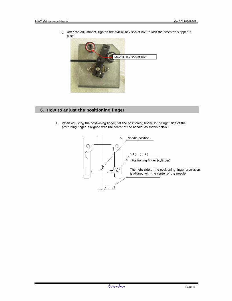
6. How to adjust the positioning finger
1. When adjusting the positioning finger, set the positioning finger so the right side of the
protruding finger is aligned with the center of the needle, as shown below.
M4x18 Hex socket bolt
Positioning finger (cylinder)
The right side of the positioning finger protrusion is aligned with the center of the needle.
Needle position

MK-7 Maintenance Manual Ver.20120809R02
Page 13
18.9
7. Trimmer troubleshooting and adjustments
<Case 1 > Situation : Upper thread is cut, but the lower thread is not cut. Reason: The drive knife might not be catching the lower thread because the lower thread is loose
and out of position when trimming. This can be brought on by improper tension balance of the upper and lower threads and/or types of upper thread.
Solution: In this case, check the tension balance of the upper and lower threads and adjust
accordingly. If still a problem, change the values of all the following parameters. MSU2: #08 ATC type 2 MSU1: #23 Trim option -151 MC: Trim vector 35
<Case 2 > Situation : Both the upper and lower threads are not cut.
Reason 1: The setting of the drive knife and fixed knife may not be adjusted correctly. Solution 1: Please refer to section “4. How to adjust the pressure of the knives” on Page 8. Reason 2: The cutting position of the drive knife might not be set properly. Solution 2: Check the cutting position of the driver knife with the following procedure.
1) Turn the machine OFF.
2) Manually rotate the trimmer cam counter-clockwise so the connection rod moves to its furthest travel limit to the right as shown in the following photos. There should also be a White line painted on the trim lever as shown below. The trimmer cam pin should line up with the White line (as shown) when in the proper position.
No. QJ270131 Part trimmer cam MK7-T
Connection rod
The figure at the left describes the position of cam when the connection rod moves to its furthest travel limit to the right. The side of the drive cam compared to the side of the trimmer motor bracket should be at an angle of 18.9 degrees when in the correct stop position.
White Line
Cam Pin

MK-7 Maintenance Manual Ver.20120809R02
Page 14
M4X6 Hex Socket bolt
Push forward Lower thread knife driving lever (upper)
Push forward
3) Loosen the M4x6 hex socket bolt for the driving lever.
4) Push the lower thread knife driving lever (upper) forward until it will not move any
further. (The driving knife should be pushed against the fixing knife fixing screw.)
5) Tighten the M4x6 hex socket bolt to lock the lever in place.
6) Double check whether or not the driving pin is visible towards the front side of the inspection hole in the needle plate. The photo and figure below show the proper position.
7) Execute a manual trim operation to check whether the thread cuts properly.
No. KX270010
Parts Fixing screw for fixing knife
No. QJ270020 Parts Driving knife MK7-T
Inspection Hole
This line indicates the middle of the Driving Pin. The Driving Pin must be close to the front edge of the hole.
Driving Pin
MK-7 Maintenance Manual Ver.20120809R02
Page 15
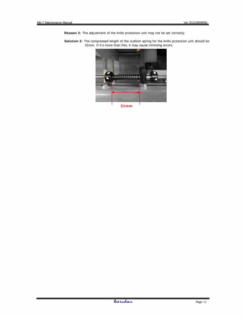
Reason 3: The adjustment of the knife protection unit may not be set correctly. Solution 3: The compressed length of the cushion spring for the knife protection unit should be
31mm. If it’s more than this, it may cause trimming errors.
31mm
MK-7 Maintenance Manual Ver.20120809R02
Page 16
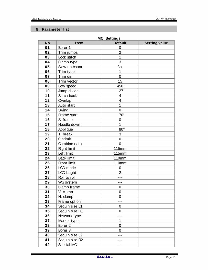
8. Parameter list
MC Settings No Item Default Setting value 01 Borer 1 0 02 Trim jumps 2 03 Lock stitch 1 04 Clamp type 3 05 Slow up count 3st 06 Trim type 1 07 Trim dir 0 08 Trim vector 15 09 Low speed 450 10 Jump divide 127 11 Stitch back 4 12 Overlap 4 13 Auto start 1 14 Swing 0 15 Frame start 70° 16 S. frame 0 17 Needle down 1 18 Applique 80° 19 T. break 3 20 0 admit 0 21 Combine data 0 22 Right limit 115mm 23 Left limit 115mm 24 Back limit 110mm 25 Front limit 110mm 26 LCD mode 0 27 LCD bright 2 28 Roll to roll --- 29 WS system --- 30 Clamp frame 0 31 V. clamp 0 32 H. clamp 0 33 Frame option --- 34 Sequin size L1 0 35 Sequin size R1 0 36 Network type --- 37 Marker type 1 38 Borer 2 0 39 Borer 3 0 40 Sequin size L2 --- 41 Sequin size R2 --- 42 Special MC ---

MK-7 Maintenance Manual Ver.20120809R02
Page 17
MSU1, MSU2 settings
MSU2 setting list
No. Item Default Set value
01 MSU2 protect --- 02 MSU1 password 5 03 Heads --- 04 Needles 9 05 Max. speed 1000 06 Slow down start 45 07 Slow down speed 600 08 ATC type 1 4 09 Color motor type --- 10 Brake type --- 11 Motor ratio 267 12 Stop angle 240 13 P. coder 0 14 F. motor type 2 15 F. move pattern 2 16 V. motor 1 17 H. motor 0 18 V. sensor 1 19 H. sensor 1 20 Origin sensor 1 21 Jump on angle 190 22 Jump off angle 120 23 Roll to roll type --- 24 WS type --- 25 WS head space --- 26 LSC type --- 27 T. break type --- 28 Sequin device 0 29 Bobbin changer --- 30 Chenille type --- 31 Jump on delay 25ms 32 Jump off delay 25ms
MSU1 setting list
No. Item Default Set value
01 MC Change 1 2 02 UTSM 0 03 T. break off 10 04 Float speed 120 05 Jump on speed 650 06 Cap max. speed 650 07 Slider off time 500 08 Fork off time 540 09 Trim motor off 30 10 ATC option 0 11 Clamp off angle 295 12 Color motor off 5 13 Vector control 1 14 Light curtain 0 15 Network 0 16 Detect disable 0 17 F. motor option 0 18 B. changer time 0 19 M. up 10/Hz 0ms 20 M. down 10/Hz 0ms 21 Clamp control 0 22 F. move mode 0 23 Trim option 0