mm - pompe garbarino · mm fire fighting naval pumps pompe navali antincendio description of the...
TRANSCRIPT

MMFire fighting naval pumps
Pompe navali antincendio

72 73
MMFIRE FIGHTING NAVAL PUMPSPOMPE NAVALI ANTINCENDIO
DESCRIPTION OF THE ELECTRIC PUMPThe electric pump mod. MM 100/125 65 and 130 t/h is horizontal split casing type with two opposite centrifugal impellers.The division of the body is on lhe horizontal plane in or-der to minimum and to simplify maintenance. The elec-tric motor is an asynchronous three-phase type, which is connected to the pump by means of an elastic coupling, mounted on a frame structure which is made of electro-welded steel. The special balancing of the pump and the specific construction of the base determine the sturdiness of the unit, which permits to reduce to a minimum the structural noise level transmitted to the ship hull. Normally, the base is fixed to the hull with four resilient blocks, which filter the noise transmitted by high frequencies.
DESCRIZIONE DELLA ELETTROPOMPAL’elettropompa tipo MM 100/125 da 65 e 130 t/h ad asse orizzontale è di tipo a divisione assiale con due giranti centrifughe contrapposte. La divisione del corpo è sul piano orizzontale in modo da semplificare la manutenzione.Il motore elettrico è asincrono trifase, collegato alla pompa mediante giunto elastico, su basamento in acciaio elettrosaldato.Il particolare bilanciamento della pompa e la speciale costruzione del basamento, determinano la rigidità del gruppo che permette valori minimi di rumore strutturale trasmesso allo scafo della nave.
Normalmente il basamento è fissato a scafo previa interposizione di quattro resilienti che filtrano il rumore trasmesso alle alte frequenze.
TESTS FOR TYPE APPROVALTesting carried out according to the Standards shown in Table UMM 1008, May 1984 issue, of NAVALCOSTARMI:a - Inspection and checking of integrityb - Test of hydrostatic pressurec - Test of voltage applied between electric phasesd - Performance teste - Test of sealing and alignmentf - Endurance test over 700 hours with more than 100 start-upsg - Test of operation in inclined positionh - Test of self-induced vibrations and structural noisei - Impact and mechanical ambient vibration testl - Test of performances after impact and vibrationsm - Strip down and reassembly.Especially these tests have been carried out according lo the program transmitted by MARIPERMAN from La Spezia, al which the Delegates from MARIPERMAN and NAVALGE-NARMI from Torino attended.
PROVE DI OMOLOGAZIONECollaudi effettuati secondo la normativa riportata nella tabella UMM 1008, ed. Maggio 1984, di NAVALCOSTARMI:a - Ispezione e controllo integritàb - Prova di pressione idrostaticac - Prova di tensione applicala tra le lasid - Prova delle prestazioni
72 73
MU
MU
L/LD
SM
CA
VS
VL
CN
ZNG
/GH
BT
AD
MM
PIN
SWL
MPF
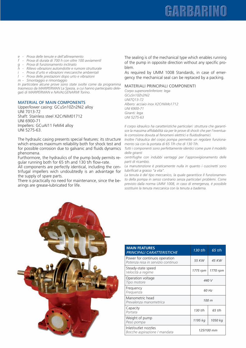
MAIN FEATURESPRINCIPALI CARATTERISTICHE
130 t/h 65 t/h
Power for continuos operationPotenza resa in servizio continuo 55 KW 45 KW
Steady-state speedVelocità a regime 1775 rpm 1770 rpm
Operation voltageTipo motore 440 V
FrequencyFrequenza 60 Hz
Manometric headPrevalenza manometrica 100 m
CapacityPortata 130 t/h 65 t/h
Weight of pumpPeso pompa 1195 kg 1050 kg
Inlet/outlet nozzlesBocche aspirazione / mandata 125/100 mm
e - Prova delle tenute e dell’allineamentof - Prova di durala di 700 h con oltre 100 avviamentlg - Prova di funzionamento inclinatoh - Rilievo vibrazioni autoindotte e rumore strutturalei - Prova d’urto e vibrazioni meccaniche ambientalil - Prova delle prestazioni dopo urto e vibrazionim - Smontaggio e rimontaggioIn particolare alcune prove sono state svolte come da programma trasmesso da MARIPERMAN La Spezia, a cui hanno partecipato dele-gati di MARIPERMAN e NAVALGENARMI Torino.
MATERIAL OF MAIN COMPONENTSUpper/lower casing: GCuSn10Zn2Ni2 alloyUNI 7013-72Shaft: Stainless steel X2CrNiM01712UNI 6900-71Impellers: GCuAI11 FeMi4 alloyUNI 5275-63.
The hydraulic casing presents special features: its structure which ensures maximum reliability both for shock test andfor possible corrosion due to galvanic and fluids dynamics phenomena.Furthormore, the hydraulics of the pump body permits re-gular running both for 65 t/h and 130 t/h flow-rate.All components are perfectly identical, including the cen-trifugal impellers wich undoubtedly is an advantage for the supply of spare parts.There is practically no need for maintenance, since the be-arings are grease-Iubricated for life.
The sealing is of the mechanical type which enables running of the pump in opposite direction without any specific pro-blem.As required by UMM 1008 Standards, in case of emer-gency the mechanical seal can be reptaced by a packing.
MATERIALI PRINCIPALI COMPONENTICorpo supenore/inferiore: legaGCuSn10Zn2Ni2UNI7Q13-72Albero: acciaio inox X2CrNiMo1712UNI 6900-71Giranti: legaUNI 5275-63
Il corpo idraulico ha caratteristiche particolari: struttura che garanti-sce la massima affidabilità sia per le prove di shock che per l’eventua-le corrosione dovuta al fenomeni elettrici e fluidodinamici.Inoltre l’idraulica del corpo pompa permette un regolare funziona-mento sia con la portata di 65 T/h che di 130 T/h.Tutti i componenti sono perfettamente identici come pure il modello delle giranticentrifughe con indubbi vantaggi per l’approwigionamento delle parti di ricambio.La manutenzione è praticamente nulla in quanto i cuscinetti sono lubrificati a grasso “a vita”.La tenuta è del tipo meccanico, la quale garantisce Il funzionamen-to della pompa in senso contrario senza particolari problemi. Come previsto dalla norma UMM 1008, in caso di emergenza, é possibile sostituire la tenuta meccanica con la tenuta a baderna.
74 75
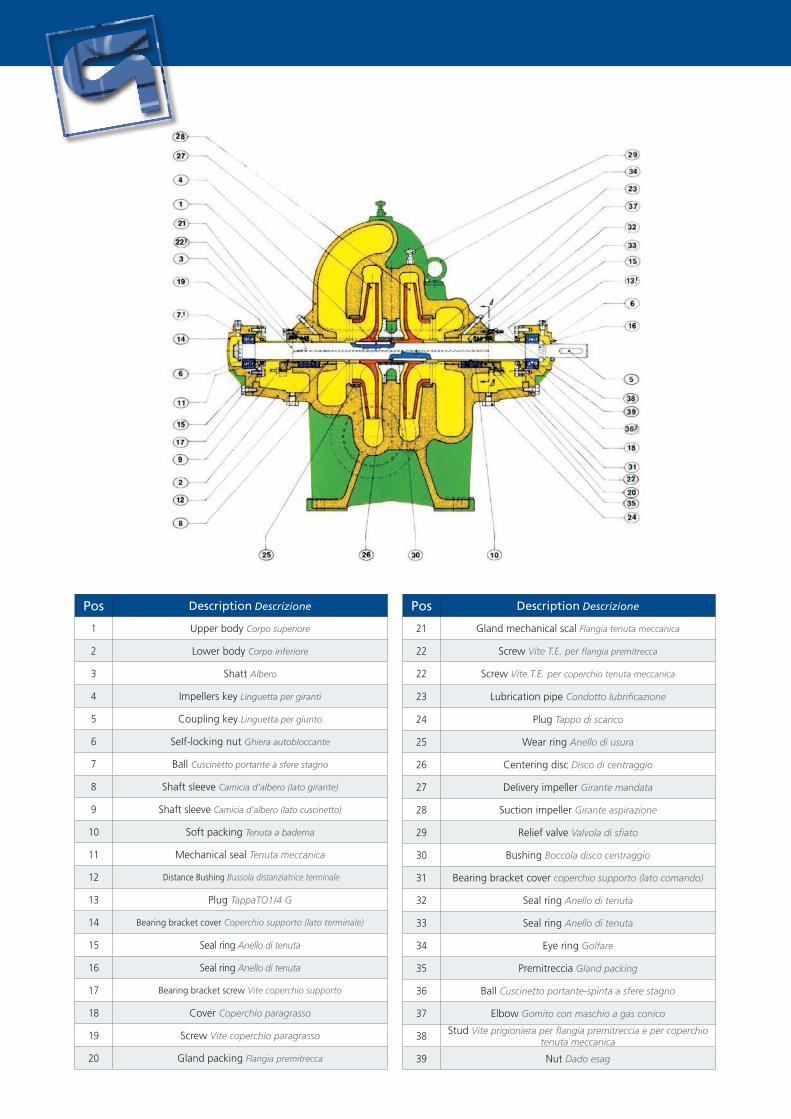
Pos Description Descrizione
1 Upper body Corpo superiore
2 Lower body Corpo inferiore
3 Shatt Albero
4 Impellers key Linguetta per giranti
5 Coupling key Linguetta per giunto
6 SeIf-locking nut Ghiera autobloccante
7 Ball Cuscinetto portante a sfere stagno
8 Shaft sleeve Camicia d’albero (Iato girante)
9 Shaft sleeve Camicia d’albero (Iato cuscinetto)
10 Soft packing Tenuta a baderna
11 Mechanical seal Tenuta meccanica
12 Distance Bushing Bussola distanziatrice terminale
13 Plug TappaTO1/4 G
14 Bearing bracket cover Coperchio supporto (Iato terminale)
15 Seal ring Anello di tenuta
16 Seal ring Anello di tenuta
17 Bearing bracket screw Vite coperchio supporto
18 Cover Coperchio paragrasso
19 Screw Vite coperchio paragrasso
20 Gland packing Flangia premitrecca
Pos Description Descrizione
21 Gland mechanical scal Flangia tenuta meccanica
22 Screw Vite T.E. per flangia premitrecca
22 Screw Vite T.E. per coperchio tenuta meccanica
23 Lubrication pipe Condotto Iubrificazione
24 Plug Tappo di scarico
25 Wear ring Anello di usura
26 Centering disc Disco di centraggio
27 DeIivery impeller Girante mandata
28 Suction impeller Girante aspirazione
29 Relief valve Valvola di sfiato
30 Bushing Boccola disco centraggio
31 Bearing bracket cover coperchio supporto (lato comando)
32 Seal ring Anello di tenuta
33 Seal ring Anello di tenuta
34 Eye ring Golfare
35 Premitreccia Gland packing
36 Ball Cuscinetto portante-spinta a sfere stagno
37 Elbow Gomito con maschio a gas conico
38 Stud Vite prigioniera per flangia premitreccia e per coperchio tenuta meccanica
39 Nut Dado esag

74 75
MU
MU
L/LD
SM
CA
VS
VL
CN
ZNG
/GH
BT
AD
MM
PIN
SWL
MPF
Characteristic test curves with measurement of delivery rate Head - Input power and required NPSH
Curve caratteristiche di collaudo con rilievo della portata Prevalenza - Potenza assorbita e NPSH richiesto
TEST BENCH BANCO PROVE
Run for structural noise measurementFase di rilievo rumore strutturale
Diagramma di funzionamento pompa tipo MM 100/125130 T/h - 1750 giri
Diagramma di funzionamento pompa tipo MM 100/12565 T/h - 1750 giri
H
130
120
110
100
90
80
70
60
50
H
130
120
110
100
90
80
70
60
50
90
70
50
30
10
60
50
40
30
20
10
5
0
10
5
0
20 40 50 60 100 120 140 160 180 Q 15 30 45 60 75 90 105 120 135 Q
NPS
H
NPS
H
HP
HP
m.c
.l.
m.c
.l.
mc/h. mc/h.
www.pompegarbarino.com
Atex on request
POMPE GARBARINO S.p.A.
Headquarters:Via Marenco, 44 - 15011 Acqui Terme (AL) - Italy - Tel. +39 0144.388671 - Fax +39 0144.55260
E-mail: [email protected]
Milan Branch:Viale Andrea Doria, 31 - 20124 Milano - Italy - Tel. +39 02.67070037 - Fax +39 02.67070097 w
ww.lizea.com