mmf links, eq and fecgrouper.ieee.org/.../nov11/king_01_1111_ng100goptx.pdfmmf links, eq and fec...
TRANSCRIPT

MMF links, EQ and FEC
November 2011Jonathan King, Finisar
Sudeep Bhoja, Broadcom
1

Supporters and contributors
• Tim Moran Finisar• John Petrilla Avago Technologies• David Cunningham Avago Technologies• Piers Dawe IPtronics
2

Introduction
• Estimates of MMF link improvements possible with some known techniques are presented:– Tx equalization– FEC (two flavours)– Rx chain equalization (FFE and FFE/DFE)
3
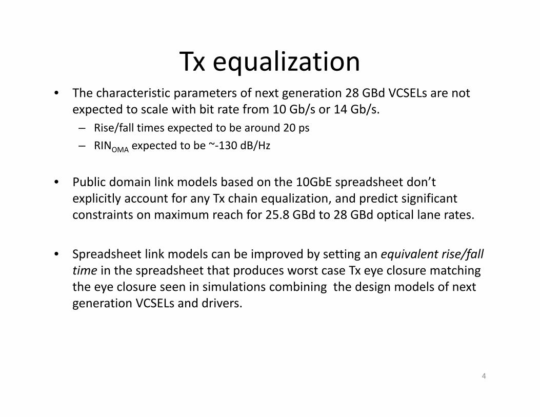
Tx equalization • The characteristic parameters of next generation 28 GBd VCSELs are not
expected to scale with bit rate from 10 Gb/s or 14 Gb/s.– Rise/fall times expected to be around 20 ps– RINOMA expected to be ~‐130 dB/Hz
• Public domain link models based on the 10GbE spreadsheet don’t explicitly account for any Tx chain equalization, and predict significant constraints on maximum reach for 25.8 GBd to 28 GBd optical lane rates.
• Spreadsheet link models can be improved by setting an equivalent rise/fall time in the spreadsheet that produces worst case Tx eye closure matching the eye closure seen in simulations combining the design models of next generation VCSELs and drivers.
4

TxEQ: driver/equalizer + VCSEL simulation
5
Simulated output eye at 28 GBdwith Tx equalization activated
eye closure = 1.5 dB
0
1
2
3
4
0 1 2 3
comp1
(eye closure without Tx equalization = 2.6 dB)
Notes: The simulations used a transistor level design model of a low power (~30 mW per lane for the EQ functionality) Tx driver/EQ, and design specific rate equation model of a high speed VCSEL design operating at high temperature. Although the implementation details are not described, the indicated range of eye improvement is helpful for setting objectives.
Retimed Input Data
EQ VCSELdriver
VCSEL
Schematic equalized Tx chain
EQ off
EQ on
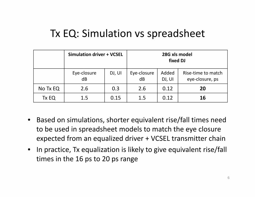
Tx EQ: Simulation vs spreadsheet
Simulation driver + VCSEL 28G xls modelfixed DJ
Eye‐closure dB
DJ, UI Eye‐closuredB
Added DJ, UI
Rise‐time to matcheye‐closure, ps
No Tx EQ 2.6 0.3 2.6 0.12 20
Tx EQ 1.5 0.15 1.5 0.12 16
6
• Based on simulations, shorter equivalent rise/fall times need to be used in spreadsheet models to match the eye closure expected from an equalized driver + VCSEL transmitter chain
• In practice, Tx equalization is likely to give equivalent rise/fall times in the 16 ps to 20 ps range
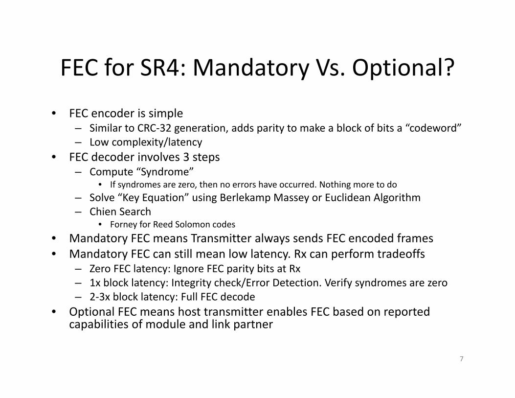
FEC for SR4: Mandatory Vs. Optional?
• FEC encoder is simple– Similar to CRC‐32 generation, adds parity to make a block of bits a “codeword”– Low complexity/latency
• FEC decoder involves 3 steps– Compute “Syndrome”
• If syndromes are zero, then no errors have occurred. Nothing more to do– Solve “Key Equation” using Berlekamp Massey or Euclidean Algorithm– Chien Search
• Forney for Reed Solomon codes • Mandatory FEC means Transmitter always sends FEC encoded frames • Mandatory FEC can still mean low latency. Rx can perform tradeoffs
– Zero FEC latency: Ignore FEC parity bits at Rx – 1x block latency: Integrity check/Error Detection. Verify syndromes are zero– 2‐3x block latency: Full FEC decode
• Optional FEC means host transmitter enables FEC based on reported capabilities of module and link partner
7

25.5 26 26.5 27 27.5 28 28.5 290
10
20
30
40
50
60
70
80
90
100
Bit Rate (Gb/s)
Blo
ck la
tenc
y (n
s)
Tradeoff of block latency vs Rate for Hamming sphere packing bound
6.5dB Coding gain7dB Coding gain8dB Coding gain
FEC Latency vs. overhead• Choice of FEC parameters involves a triple tradeoff
– Latency– Additional overhead causes over clocking (higher signaling rate) or reduced data rate– Coding gain
• The block latency increases sharply as the rate approaches 100GE‐LR4 rate• For lowest latency, higher overhead (28 vs. 25.8 GBd or 92 vs. 100 Gb/s) is
preferred
• However, if mandatory FEC is desirable, 28 GBd might impose a burden on all ports
• Alternate transcoding, 512B/513B has been proposed to lower the FEC overhead
8

Spreadsheet link model with and without FEC • Initial calculations of non‐FEC and FEC enabled reach using modified ‘10GE
spreadsheet’ model ‐ not exact, perhaps a compass• Link assumptions:
– Tx/VCSEL: two effective rise fall times used, 20 ps (simple Tx chain), and 16 ps(some Tx equalization)
• Tx_OMA min of ‐2 dBm , 0.6 nm max RMS spectral width, ‐130 dB/Hz RINOMA, 840 nm worst case centre wavelength, 0.12 UI added DJ
– Channel: OM4, 4400 MHz.km, 1.5 dB total connector loss– Receiver: ‐7.6 dBm sensitivity at 25.8 GBd, BER 10‐12
• includes nominal 1 dB allowance for penalties due to multiple parallel channels• de‐rated by the square root of the bit rate, and by 10.log(Q), to give ‐10 dBm for 25.8 GBd,
BER=3x10‐5, and ‐10.2 dBm for 28.05 GBd, BER=9.9x10‐5
• FEC assumptions:– High and low latency FEC flavours, ~the bookends in Gustlin_02a_0311
Block size Rate Gb/s 3x block latency Raw coding gain, 10‐15 BER in for 10‐15 out Notes
9979 bits 25.8 ~300 ns 5.9 dB 3.06x10‐5 ‘High latency’, Q=~4
906 bits 28 ~30 ns 6.6 dB 9.96x10‐5 ‘Low latency’, Q=~3.8
9

Summary results 1VCSEL effective rise fall time = 20 ps (no Tx equalization)
Rate/FEC Reach limitdefinition
OM4 reach
Typ. latency:50m fiber + FEC
Max. latency:max reach + FEC
Notes
25.8 GBd,no FEC
power budget
70 m 250 ns 350 ns ~2.5 dB VECP
25.8 GBd,high latency FEC
power budget
155 m 550 ns 1075 ns high ~4.5dB VECP
25.8 GBd,high latency FEC
3.6 dB VECP
125 m 550 ns 925 ns 1.7 dB margin for spec relaxation
25.8 GBd,high latency FEC
3.0 dB VECP
100 m 550 ns 800 ns 2.6 dB margin for spec relaxation
28 GBd,low latency FEC
power budget
140 m 280 ns 730 ns high ~4.8 dB VECP !
28 GBd,low latency FEC
3.6 dB VECP
100 m 280 ns 530 ns 2.0 dB margin for spec relaxation
10

Summary results 2VCSEL effective rise fall time = 16 ps (some Tx equalization)
Rate/FEC Reach limitdefinition
OM4 reach
Typ. latency:50m fiber + FEC
Max. latency:max reach + FEC
Notes
25.8 GBd,no FEC
power budget
100 m 250 ns 500 ns ~2.2 dB VECP
25.8 GBd,high latency FEC
power budget
170 m 550 ns 1150 ns high ~4 dB VECP !
25.8 GBd,high latency FEC
3.6 dB VECP
155 m 550 ns 1075 ns 1.2 dB margin for spec relaxation
25.8 GBd,high latency FEC
3.0 dB VECP
135 m 550 ns 975 ns 2.2 dB margin for spec relaxation
28 GBd,low latency FEC
power budget
160 m 280 ns 830 ns high ~4.5 dB VECP !
28 GBd,low latency FEC
3.6 dB VECP
135 m 280 ns 705 ns 1.7 dB margin for spec relaxation
11

Rx chain equalization
12
• PIE‐L and PIE‐D used to calculate equalized power penalty vs distance– The PIE metrics (Penalty for Ideal Equalizer) refer to FFE and FFE/DFE based equalizers of
with infinite number of taps. In practice, an equalizer with a finite, modest number of taps can get very close to the ideal equalizer penalty
– Tx/VCSEL: 20 ps rise fall times, Rx bandwidth 15 GHz, OM3 fibre
0 50 100 1501
2
3
4
5
6
7
OM3 Link length (m)
Pow
er P
enal
ty (d
Bo)
OM3 EDC simulations. Tx Rise Time is 20ps. Rx BW is 15GHz
UnequalizedIdeal FFEIdeal FFE+DFE

Concluding notesTx equalization • Reduces Tx eye closure by about 1 dB• May allow an effective rise time between 16 and 20 ps for spreadsheet modeling• Power efficient: ~30 mW/lane inside the module
FEC• Allows links to extend to their ISI limited reach,
• about a 40% increase in distance ‐ enables 100+ m links on OM4 for slow lasers• … and can provide an extra 1 to 2 dB link budget margin
• for example could be used to relax the Tx or Rx specs used here• … can be power efficient ~50 mW/lane (depending on process) outside moduleNotes: Link latency is dominated by the fibre ‐ FEC adds the equivalent of 6 m to 60 m of fiber
• Greater overheads (higher bit‐rates) reduce FEC latency, but reduce max reach
Rx equalization – Reduces vertical eye closure penalty of a 100 m OM3 link by 1 to 2 dB (depending on
complexity)– Many choices are available. Continuous Time Linear Equalizer (CTLE), FFE or DFE– Current power consumption estimates: 100 mW for linear TIA, 100‐150 mW for EDC.
Power consumption for EDC in 28 nm CMOS can be further reduced to 50‐75 mW. 13

Summary table Technology Approximate
power/lanebenefit Notes
Full retiming in module
~500 mW relaxed host specs, partitioned testing
per Tx Rx pair*
Tx EQ ~30 mW ~1 dB
FEC ~50 mW 1 to 2.5 dB latency vs overhead
Rx EQ ~150‐200 mW 1 to 2 dB for FFE/DFE
Rx chain CTLE or fixed peaking
<30 mW ? ~1 dB ? power burn vsbenefit TBD
14
* ~10mW per Gb/s per CDR, expected to reduce in next few years

Thank you !
15

back up
• Link models for 20ps rise/fall time
16

25.8 Gb/s no FEC
• Reach limited by power budget: ~70 m OM4– ~2.5 dB vertical eye closure penalty
17
Spreadsheet by Del Hanson, David Cunningham, Piers Dawe, David Dolfi Agilent Technologies Rev. 3.2/3 This file ofBasics Input= Bold Ts(20-80) 20 ps Case: Attenuation= 3.5 dB/km Model/format rev3.1.16a of
Q= 7.04 Ts(10-90) 30 ps Target Target reach 0.070 km Fiber at 850 nm NomSens OMA -7.61 dBm Margin 0.10 dB atBase Rate= 25781 MBd RIN(OMA) -130 dB/Hz and L_start= 0.002 km C_att= 1.00 Receive Refl Rx -12 dB Answer! 0.07 km
Transmitter RIN at MinER -138.0 dB/Hz graph L_inc= 0.007 km Attenuation= 3.62 dB/km Rec_BW= ##### MHz st Rx BW 18750 MHzWavelength Uc 840 nm RIN_Coef= 0.70 Power Budget P= 5.61 dB at 840 nm c_rx 329 ns.MHzUw (see notes) 0.60 nm Det.Jitter 4.7 ps inc. DCD Connections C 1.5 dB Disp. min. Uo= 1316 nm T_rx(10-90) 16.0 ps Test Source ER=
Tx pwr OMA= -2.00 dBm DCD_DJ= 2.3273 ps TP3Pwr.Bud.-Conn.Loss 4.11 dB Disp. So= 0.103 ps/nm^2*km TP4 Eye 8 ps Test Tx 6.5 dBMin. Ext Ratio= 3.65 dB Effect. DJ= 0.06 (UI) ex DCD C1= 480 ns.MHz Disp. D1= ##### ps/(nm.km) Opening (=Tx eyTestERpe 1.98 dBo
"Worst"ave.TxPwr -1.0 dBm MPN k(OMA) 0.3 Reflection Noise factor 0 no units RMS Baseline wander SD 0.025 fraction of 1/2 eyeExt. ratio penalty 4.01 dBo Tx eye height 46.6% Effective Rate 27427 MBd (not in use) 10 V.E.C.P. 2.47 dBoTx maskX1= 0.3 UI Refl Tx -12 dB Tb_eff= 36 ps BWm= 4400 MHz*km P_BLW(no ISI) 0.07 dB Stressed
X2= 0.4 UI ModalNoisePen 0.3 dB Effective Rec Eye 0.21 UI Eff. BWm= ##### MHz*km P_BLW 0.07 dB Rx sensY1= 0.25 Tx mask top 0.2 UI Pisi P Eye P_DJ P_DJ Preflection Pcross Ptotal <Ptotal LP Pen OMA
L Patt Ch IL D1.L D2.L BWcd effBWm Te Tc central corners central corners central Beta SDmpn Pmpn Prin central central corners central Margin central(km) (dB) (dB) ps/nm ps/nm (MHz) (MHz) (ps) (ps) J=0, dB (dB) (dB) (dB) (dB) (dB) (dB) (dB) (dB) (dB) (dB) (dB) (dBm)0.002 0.01 1.51 -0.22 0.00 1E+06 ###### 30 34 1.85 0.24 0.02 0.17 -1E-02 0.00 0.00 0.16 2.33 2.73 2.3 1.8 -4.00.002 0.01 1.51 -0.2 0.00 ##### ###### 30 34 1.85 0.24 0.02 0.17 0 -0.01 0.00 0.00 0.61 0.30 3.1 3.5 3.1 1.0 -4.70.009 0.03 1.53 -1.0 0.00 ##### ###### 30 34 1.85 0.24 0.02 0.17 0 -0.05 0.00 0.00 0.61 0.31 3.1 3.5 3.1 1.0 -4.70.016 0.06 1.56 -1.7 0.00 ##### ###### 31 34 1.87 0.24 0.02 0.17 0 -0.09 0.00 0.00 0.60 0.31 3.2 3.6 3.1 1.0 -4.70.022 0.08 1.58 -2.4 0.00 ##### ###### 31 35 1.89 0.25 0.02 0.18 0 -0.13 0.00 0.00 0.60 0.31 3.2 3.6 3.1 0.9 -4.70.029 0.11 1.61 -3.2 0.00 98,453 ###### 31 35 1.93 0.25 0.02 0.18 0 -0.16 0.01 0.00 0.59 0.31 3.3 3.7 3.2 0.8 -4.80.036 0.13 1.63 -3.9 0.00 79,857 ###### 31 35 1.97 0.25 0.02 0.18 0 -0.20 0.01 0.01 0.59 0.32 3.3 3.7 3.2 0.8 -4.80.043 0.16 1.66 -4.6 0.00 67,169 ###### 32 35 2.02 0.25 0.02 0.18 0 -0.24 0.01 0.02 0.58 0.33 3.4 3.8 3.3 0.7 -4.80.05 0.18 1.68 -5.4 0.00 57,961 88,710 32 36 2.08 0.25 0.02 0.18 0 -0.28 0.02 0.03 0.57 0.35 3.5 3.9 3.4 0.6 -4.90.056 0.20 1.70 -6.1 0.00 50,972 78,014 32 36 2.15 0.25 0.02 0.18 0 -0.32 0.02 0.04 0.57 0.37 3.7 4.1 3.5 0.4 -4.90.063 0.23 1.73 -6.9 0.00 45,488 69,620 33 37 2.23 0.25 0.02 0.18 0 -0.35 0.02 0.07 0.57 0.40 3.8 4.2 3.6 0.3 -5.00.07 0.25 1.75 -7.6 0.00 41,069 62,857 33 37 2.32 0.25 0.02 0.18 0 -0.39 0.03 0.10 0.57 0.45 4.0 4.4 3.8 0.1 -5.0
17-Oct-0110GEPBud3_1_16a.xls850nm serial newMMF 31-Oct-01

25.8 Gb/s ‘high latency’ FEC (power budget limit)
• Reach limited by power budget is 155 m OM4– ~4.4 dB vertical eye closure penalty (too high)
18
Spreadsheet by Del Hanson, David Cunningham, Piers Dawe, David Dolfi Agilent Technologies Rev. 3.2/3 This file ofBasics Input= Bold Ts(20-80) 20 ps Case: Attenuation= 3.5 dB/km Model/format rev3.1.16a of
Q= 4.04 Ts(10-90) 30 ps Target Target reach 0.155 km Fiber at 850 nm NomSens OMA -10.03 dBm Margin 0.14 dB atBase Rate= 25781 MBd RIN(OMA) -130 dB/Hz and L_start= 0.002 km C_att= 1.00 Receive Refl Rx -12 dB Answer! 0.155 km
Transmitter RIN at MinER -138.0 dB/Hz graph L_inc= 0.015 km Attenuation= 3.62 dB/km Rec_BW= ##### MHz st Rx BW 18750 MHzWavelength Uc 840 nm RIN_Coef= 0.70 Power Budget P= 8.03 dB at 840 nm c_rx 329 ns.MHzUw (see notes) 0.60 nm Det.Jitter 4.7 ps inc. DCD Connections C 1.5 dB Disp. min. Uo= 1316 nm T_rx(10-90) 16.0 ps Test Source ER=
Tx pwr OMA= -2.00 dBm DCD_DJ= 2.33 ps TP3Pwr.Bud.-Conn.Loss 6.525 dB Disp. So= 0.103 ps/nm^2*km TP4 Eye 8 ps Test Tx 6.5 dBMin. Ext Ratio= 3.65 dB Effect. DJ= 0.06 (UI) ex DCD C1= 480 ns.MHz Disp. D1= ##### ps/(nm.km) Opening (=Tx eyTestERpe 1.98 dBo
"Worst"ave.TxPwr -1.0 dBm MPN k(OMA) 0.3 Reflection Noise factor 0 no units RMS Baseline wander SD 0.025 fraction of 1/2 eyeExt. ratio penalty 4.01 dBo Tx eye height 46.6% Effective Rate 27429 MBd (not in use) 10 V.E.C.P. 4.40 dBoTx maskX1= 0.3 UI Refl Tx -12 dB Tb_eff= 36 ps BWm= 4400 MHz*km P_BLW(no ISI) 0.02 dB Stressed
X2= 0.4 UI ModalNoisePen 0.3 dB Effective Rec Eye 0.21 UI Eff. BWm= ##### MHz*km P_BLW 0.02 dB Rx sensY1= 0.25 Tx mask top 0.2 UI Pisi P Eye P_DJ P_DJ Preflection Pcross Ptotal <Ptotal LP Pen OMA
L Patt Ch IL D1.L D2.L BWcd effBWm Te Tc central corners central corners central Beta SDmpn Pmpn Prin central central corners central Margin central(km) (dB) (dB) ps/nm ps/nm (MHz) (MHz) (ps) (ps) J=0, dB (dB) (dB) (dB) (dB) (dB) (dB) (dB) (dB) (dB) (dB) (dB) (dBm)0.002 0.01 1.51 -0.22 0.00 1E+06 ###### 30 34 1.85 0.24 0.02 0.18 -1E-02 0.00 0.00 0.05 2.22 2.62 2.2 4.3 -4.00.002 0.01 1.51 -0.2 0.00 ##### ###### 30 34 1.85 0.24 0.02 0.18 0 -0.01 0.00 0.00 0.18 0.07 2.4 2.8 2.4 4.1 -4.20.017 0.06 1.56 -1.9 0.00 ##### ###### 31 34 1.87 0.24 0.02 0.18 0 -0.10 0.00 0.00 0.18 0.07 2.5 2.9 2.4 4.0 -4.20.033 0.12 1.62 -3.5 0.00 88,185 ###### 31 35 1.95 0.25 0.02 0.18 0 -0.18 0.01 0.00 0.18 0.08 2.6 3.0 2.5 3.9 -4.30.048 0.17 1.67 -5.2 0.00 60,018 91,858 32 36 2.07 0.25 0.02 0.18 0 -0.27 0.01 0.01 0.17 0.08 2.8 3.2 2.7 3.7 -4.30.063 0.23 1.73 -6.9 0.00 45,488 69,620 33 37 2.23 0.25 0.02 0.18 0 -0.35 0.02 0.02 0.17 0.09 3.1 3.5 2.8 3.5 -4.40.079 0.28 1.78 -8.5 0.00 36,622 56,051 34 38 2.44 0.25 0.02 0.18 0 -0.44 0.04 0.05 0.17 0.11 3.4 3.8 3.1 3.1 -4.50.094 0.34 1.84 -10.2 0.00 30,649 46,908 36 39 2.70 0.25 0.02 0.18 0 -0.53 0.05 0.09 0.18 0.14 3.8 4.2 3.4 2.8 -4.60.109 0.40 1.90 -11.8 0.00 26,351 40,330 37 41 3.01 0.25 0.02 0.18 0 -0.61 0.07 0.16 0.19 0.18 4.3 4.7 3.9 2.3 -4.80.124 0.45 1.95 -13.5 0.01 23,110 35,370 39 42 3.37 0.25 0.02 0.18 0 -0.70 0.08 0.25 0.20 0.24 4.8 5.2 4.4 1.7 -5.00.14 0.51 2.01 -15.1 0.01 20,579 31,496 41 44 3.77 0.26 0.02 0.19 0 -0.78 0.10 0.36 0.22 0.35 5.5 6.0 5.0 1.0 -5.20.155 0.56 2.06 -16.8 0.01 18,547 28,387 43 46 4.24 0.26 0.02 0.19 0 -0.87 0.11 0.50 0.26 0.51 6.4 6.8 5.8 0.1 -5.5
17-Oct-0110GEPBud3_1_16a.xls850nm serial newMMF 31-Oct-01

25.8 Gb/s ‘high latency’ FEC (ISI limit)
• Reach limited by ~3.6 dB vertical eye closure is ~125 m OM4
19
Spreadsheet by Del Hanson, David Cunningham, Piers Dawe, David Dolfi Agilent Technologies Rev. 3.2/3 This file ofBasics Input= Bold Ts(20-80) 20 ps Case: Attenuation= 3.5 dB/km Model/format rev3.1.16a of
Q= 4.04 Ts(10-90) 30 ps Target Target reach 0.125 km Fiber at 850 nm NomSens OMA -10.03 dBm Margin 1.67 dB atBase Rate= 25781 MBd RIN(OMA) -130 dB/Hz and L_start= 0.002 km C_att= 1.00 Receive Refl Rx -12 dB Answer! 0.125 km
Transmitter RIN at MinER -138.0 dB/Hz graph L_inc= 0.012 km Attenuation= 3.62 dB/km Rec_BW= ##### MHz st Rx BW 18750 MHzWavelength Uc 840 nm RIN_Coef= 0.70 Power Budget P= 8.03 dB at 840 nm c_rx 329 ns.MHzUw (see notes) 0.60 nm Det.Jitter 4.7 ps inc. DCD Connections C 1.5 dB Disp. min. Uo= 1316 nm T_rx(10-90) 16.0 ps Test Source ER=
Tx pwr OMA= -2.00 dBm DCD_DJ= 2.33 ps TP3Pwr.Bud.-Conn.Loss 6.525 dB Disp. So= 0.103 ps/nm^2*km TP4 Eye 8 ps Test Tx 6.5 dBMin. Ext Ratio= 3.65 dB Effect. DJ= 0.06 (UI) ex DCD C1= 480 ns.MHz Disp. D1= ##### ps/(nm.km) Opening (=Tx eyTestERpe 1.98 dBo
"Worst"ave.TxPwr -1.0 dBm MPN k(OMA) 0.3 Reflection Noise factor 0 no units RMS Baseline wander SD 0.025 fraction of 1/2 eyeExt. ratio penalty 4.01 dBo Tx eye height 46.6% Effective Rate 27429 MBd (not in use) 10 V.E.C.P. 3.54 dBoTx maskX1= 0.3 UI Refl Tx -12 dB Tb_eff= 36 ps BWm= 4400 MHz*km P_BLW(no ISI) 0.02 dB Stressed
X2= 0.4 UI ModalNoisePen 0.3 dB Effective Rec Eye 0.21 UI Eff. BWm= ##### MHz*km P_BLW 0.02 dB Rx sensY1= 0.25 Tx mask top 0.2 UI Pisi P Eye P_DJ P_DJ Preflection Pcross Ptotal <Ptotal LP Pen OMA
L Patt Ch IL D1.L D2.L BWcd effBWm Te Tc central corners central corners central Beta SDmpn Pmpn Prin central central corners central Margin central(km) (dB) (dB) ps/nm ps/nm (MHz) (MHz) (ps) (ps) J=0, dB (dB) (dB) (dB) (dB) (dB) (dB) (dB) (dB) (dB) (dB) (dB) (dBm)0.002 0.01 1.51 -0.22 0.00 1E+06 ###### 30 34 1.85 0.24 0.02 0.18 -1E-02 0.00 0.00 0.05 2.22 2.62 2.2 4.3 -5.50.002 0.01 1.51 -0.2 0.00 ##### ###### 30 34 1.85 0.24 0.02 0.18 0 -0.01 0.00 0.00 0.18 0.07 2.4 2.8 2.4 4.1 -5.70.014 0.05 1.55 -1.6 0.00 ##### ###### 30 34 1.87 0.24 0.02 0.18 0 -0.08 0.00 0.00 0.18 0.07 2.5 2.9 2.4 4.0 -5.70.027 0.10 1.60 -2.9 0.00 ##### ###### 31 35 1.91 0.25 0.02 0.18 0 -0.15 0.00 0.00 0.18 0.07 2.6 3.0 2.5 3.9 -5.80.039 0.14 1.64 -4.2 0.00 73,903 ###### 31 35 1.99 0.25 0.02 0.18 0 -0.22 0.01 0.00 0.18 0.08 2.7 3.1 2.6 3.8 -5.80.051 0.19 1.69 -5.6 0.00 56,149 85,938 32 36 2.10 0.25 0.02 0.18 0 -0.29 0.02 0.01 0.17 0.08 2.9 3.3 2.7 3.7 -5.90.064 0.23 1.73 -6.9 0.00 45,273 69,291 33 37 2.24 0.25 0.02 0.18 0 -0.36 0.03 0.02 0.17 0.09 3.1 3.5 2.8 3.5 -5.90.076 0.27 1.77 -8.2 0.00 37,927 58,047 34 37 2.40 0.25 0.02 0.18 0 -0.42 0.04 0.04 0.17 0.10 3.3 3.7 3.0 3.2 -6.00.088 0.32 1.82 -9.6 0.00 32,632 49,943 35 39 2.60 0.25 0.02 0.18 0 -0.49 0.05 0.08 0.17 0.12 3.6 4.0 3.3 2.9 -6.10.10 0.36 1.86 -10.9 0.00 28,634 43,825 36 40 2.83 0.25 0.02 0.18 0 -0.56 0.06 0.12 0.18 0.15 4.0 4.4 3.6 2.6 -6.20.113 0.41 1.91 -12.2 0.00 25,509 39,042 38 41 3.09 0.25 0.02 0.18 0 -0.63 0.07 0.18 0.19 0.19 4.4 4.8 4.0 2.1 -6.30.125 0.45 1.95 -13.6 0.01 22,999 35,200 39 42 3.38 0.25 0.02 0.18 0 -0.70 0.08 0.25 0.20 0.25 4.9 5.3 4.4 1.7 -6.5
17-Oct-0110GEPBud3_1_16a.xls850nm serial newMMF 31-Oct-01

25.8 Gb/s ‘high latency’ FEC (ISI limit)
• Reach limited by ~3.0 dB vertical eye closure is 100 m OM4
20
Spreadsheet by Del Hanson, David Cunningham, Piers Dawe, David Dolfi Agilent Technologies Rev. 3.2/3 This file ofBasics Input= Bold Ts(20-80) 20 ps Case: Attenuation= 3.5 dB/km Model/format rev3.1.16a of
Q= 4.04 Ts(10-90) 30 ps Target Target reach 0.100 km Fiber at 850 nm NomSens OMA -10.03 dBm Margin 2.57 dB atBase Rate= 25781 MBd RIN(OMA) -130 dB/Hz and L_start= 0.002 km C_att= 1.00 Receive Refl Rx -12 dB Answer! 0.1 km
Transmitter RIN at MinER -138.0 dB/Hz graph L_inc= 0.01 km Attenuation= 3.62 dB/km Rec_BW= ##### MHz st Rx BW 18750 MHzWavelength Uc 840 nm RIN_Coef= 0.70 Power Budget P= 8.03 dB at 840 nm c_rx 329 ns.MHzUw (see notes) 0.60 nm Det.Jitter 4.7 ps inc. DCD Connections C 1.5 dB Disp. min. Uo= 1316 nm T_rx(10-90) 16.0 ps Test Source ER=
Tx pwr OMA= -2.00 dBm DCD_DJ= 2.33 ps TP3Pwr.Bud.-Conn.Loss 6.525 dB Disp. So= 0.103 ps/nm^2*km TP4 Eye 8 ps Test Tx 6.5 dBMin. Ext Ratio= 3.65 dB Effect. DJ= 0.06 (UI) ex DCD C1= 480 ns.MHz Disp. D1= ##### ps/(nm.km) Opening (=Tx eyTestERpe 1.98 dBo
"Worst"ave.TxPwr -1.0 dBm MPN k(OMA) 0.3 Reflection Noise factor 0 no units RMS Baseline wander SD 0.025 fraction of 1/2 eyeExt. ratio penalty 4.01 dBo Tx eye height 46.6% Effective Rate 27429 MBd (not in use) 10 V.E.C.P. 2.98 dBoTx maskX1= 0.3 UI Refl Tx -12 dB Tb_eff= 36 ps BWm= 4400 MHz*km P_BLW(no ISI) 0.02 dB Stressed
X2= 0.4 UI ModalNoisePen 0.3 dB Effective Rec Eye 0.21 UI Eff. BWm= ##### MHz*km P_BLW 0.02 dB Rx sensY1= 0.25 Tx mask top 0.2 UI Pisi P Eye P_DJ P_DJ Preflection Pcross Ptotal <Ptotal LP Pen OMA
L Patt Ch IL D1.L D2.L BWcd effBWm Te Tc central corners central corners central Beta SDmpn Pmpn Prin central central corners central Margin central(km) (dB) (dB) ps/nm ps/nm (MHz) (MHz) (ps) (ps) J=0, dB (dB) (dB) (dB) (dB) (dB) (dB) (dB) (dB) (dB) (dB) (dB) (dBm)0.002 0.01 1.51 -0.22 0.00 1E+06 ###### 30 34 1.85 0.24 0.02 0.18 -1E-02 0.00 0.00 0.05 2.22 2.62 2.2 4.3 -6.40.002 0.01 1.51 -0.2 0.00 ##### ###### 30 34 1.85 0.24 0.02 0.18 0 -0.01 0.00 0.00 0.18 0.07 2.4 2.8 2.4 4.1 -6.60.012 0.04 1.54 -1.3 0.00 ##### ###### 30 34 1.86 0.24 0.02 0.18 0 -0.07 0.00 0.00 0.18 0.07 2.5 2.9 2.4 4.0 -6.60.022 0.08 1.58 -2.3 0.00 ##### ###### 31 35 1.89 0.25 0.02 0.18 0 -0.12 0.00 0.00 0.18 0.07 2.5 2.9 2.5 4.0 -6.70.031 0.11 1.61 -3.4 0.00 91,555 ###### 31 35 1.94 0.25 0.02 0.18 0 -0.18 0.01 0.00 0.18 0.07 2.6 3.0 2.5 3.9 -6.70.041 0.15 1.65 -4.5 0.00 69,778 ###### 31 35 2.01 0.25 0.02 0.18 0 -0.23 0.01 0.00 0.17 0.08 2.7 3.1 2.6 3.8 -6.70.051 0.18 1.68 -5.5 0.00 56,369 86,275 32 36 2.10 0.25 0.02 0.18 0 -0.29 0.02 0.01 0.17 0.08 2.9 3.3 2.7 3.7 -6.80.061 0.22 1.72 -6.6 0.00 47,284 72,368 33 36 2.20 0.25 0.02 0.18 0 -0.34 0.02 0.02 0.17 0.09 3.0 3.4 2.8 3.5 -6.80.071 0.26 1.76 -7.7 0.00 40,720 62,323 33 37 2.33 0.25 0.02 0.18 0 -0.40 0.03 0.03 0.17 0.10 3.2 3.6 3.0 3.3 -6.90.08 0.29 1.79 -8.7 0.00 35,757 54,726 34 38 2.47 0.25 0.02 0.18 0 -0.45 0.04 0.05 0.17 0.11 3.4 3.8 3.1 3.1 -6.90.09 0.33 1.83 -9.8 0.00 31,872 48,780 35 39 2.64 0.25 0.02 0.18 0 -0.51 0.05 0.08 0.17 0.13 3.7 4.1 3.3 2.9 -7.00.10 0.36 1.86 -10.8 0.00 28,748 44,000 36 40 2.82 0.25 0.02 0.18 0 -0.56 0.06 0.12 0.18 0.15 4.0 4.4 3.6 2.6 -7.1
17-Oct-0110GEPBud3_1_16a.xls850nm serial newMMF 31-Oct-01

28 Gb/s ‘low latency’ FEC (power budget limit)
• Reach allowed by power budget is ~140 m OM4– but ~4.8 dB vertical eye closure (too high)
21
Spreadsheet by Del Hanson, David Cunningham, Piers Dawe, David Dolfi Agilent Technologies Rev. 3.2/3 This file ofBasics Input= Bold Ts(20-80) 20 ps Case: Attenuation= 3.5 dB/km Model/format rev3.1.16a of
Q= 3.74 Ts(10-90) 30 ps Target Target reach 0.140 km Fiber at 850 nm NomSens OMA -10.18 dBm Margin 0.08 dB atBase Rate= 28050 MBd RIN(OMA) -130 dB/Hz and L_start= 0.002 km C_att= 1.00 Receive Refl Rx -12 dB Answer! 0.14 km
Transmitter RIN at MinER -138.0 dB/Hz graph L_inc= 0.014 km Attenuation= 3.62 dB/km Rec_BW= ##### MHz st Rx BW 20400 MHzWavelength Uc 840 nm RIN_Coef= 0.70 Power Budget P= 8.18 dB at 840 nm c_rx 329 ns.MHzUw (see notes) 0.60 nm Det.Jitter 4.3 ps inc. DCD Connections C 1.5 dB Disp. min. Uo= 1316 nm T_rx(10-90) 14.7 ps Test Source ER=
Tx pwr OMA= -2.00 dBm DCD_DJ= 2.139 ps TP3Pwr.Bud.-Conn.Loss 6.676 dB Disp. So= 0.103 ps/nm^2*km TP4 Eye 7 ps Test Tx 6.5 dBMin. Ext Ratio= 3.65 dB Effect. DJ= 0.06 (UI) ex DCD C1= 480 ns.MHz Disp. D1= ##### ps/(nm.km) Opening (=Tx eyTestERpe 1.98 dBo
"Worst"ave.TxPwr -1.0 dBm MPN k(OMA) 0.3 Reflection Noise factor 0 no units RMS Baseline wander SD 0.025 fraction of 1/2 eyeExt. ratio penalty 4.01 dBo Tx eye height 40.8% Effective Rate 29840 MBd (not in use) 10 V.E.C.P. 4.77 dBoTx maskX1= 0.3 UI Refl Tx -12 dB Tb_eff= 34 ps BWm= 4400 MHz*km P_BLW(no ISI) 0.02 dB Stressed
X2= 0.4 UI ModalNoisePen 0.3 dB Effective Rec Eye 0.21 UI Eff. BWm= ##### MHz*km P_BLW 0.02 dB Rx sensY1= 0.25 Tx mask top 0.2 UI Pisi P Eye P_DJ P_DJ Preflection Pcross Ptotal <Ptotal LP Pen OMA
L Patt Ch IL D1.L D2.L BWcd effBWm Te Tc central corners central corners central Beta SDmpn Pmpn Prin central central corners central Margin central(km) (dB) (dB) ps/nm ps/nm (MHz) (MHz) (ps) (ps) J=0, dB (dB) (dB) (dB) (dB) (dB) (dB) (dB) (dB) (dB) (dB) (dB) (dBm)0.002 0.01 1.51 -0.22 0.00 1E+06 ###### 30 34 2.26 0.25 0.02 0.18 -1E-02 0.00 0.00 0.06 2.64 3.05 2.6 4.0 -3.90.002 0.01 1.51 -0.2 0.00 ##### ###### 30 34 2.26 0.25 0.02 0.18 0 -0.01 0.00 0.00 0.21 0.08 2.9 3.3 2.9 3.8 -4.10.016 0.06 1.56 -1.7 0.00 ##### ###### 31 34 2.29 0.25 0.02 0.18 0 -0.10 0.00 0.00 0.20 0.08 3.0 3.4 2.9 3.7 -4.20.03 0.11 1.61 -3.2 0.00 97,123 ###### 31 34 2.36 0.25 0.02 0.18 0 -0.18 0.01 0.00 0.20 0.09 3.1 3.5 3.0 3.6 -4.20.043 0.16 1.66 -4.7 0.00 66,241 ###### 32 35 2.48 0.25 0.02 0.18 0 -0.26 0.01 0.01 0.20 0.09 3.2 3.7 3.1 3.4 -4.30.057 0.21 1.71 -6.2 0.00 50,259 76,923 32 36 2.64 0.25 0.02 0.18 0 -0.35 0.02 0.02 0.19 0.10 3.5 3.9 3.3 3.2 -4.40.071 0.26 1.76 -7.7 0.00 40,491 61,972 34 37 2.84 0.25 0.02 0.18 0 -0.43 0.04 0.04 0.19 0.12 3.8 4.2 3.5 2.9 -4.40.085 0.31 1.81 -9.2 0.00 33,901 51,887 35 38 3.10 0.25 0.02 0.18 0 -0.52 0.05 0.08 0.20 0.14 4.1 4.6 3.8 2.5 -4.50.099 0.36 1.86 -10.7 0.00 29,157 44,625 36 39 3.40 0.25 0.02 0.18 0 -0.60 0.06 0.13 0.21 0.18 4.6 5.0 4.2 2.1 -4.70.112 0.41 1.91 -12.2 0.00 25,577 39,146 38 40 3.74 0.26 0.02 0.18 0 -0.69 0.08 0.20 0.23 0.24 5.1 5.6 4.7 1.5 -4.80.126 0.46 1.96 -13.7 0.01 22,780 34,865 39 42 4.14 0.26 0.02 0.19 0 -0.77 0.09 0.29 0.25 0.33 5.8 6.2 5.3 0.9 -5.00.14 0.51 2.01 -15.2 0.01 20,535 31,429 41 44 4.60 0.27 0.02 0.19 0 -0.85 0.11 0.40 0.29 0.48 6.6 7.0 6.1 0.1 -5.3
17-Oct-0110GEPBud3_1_16a.xls850nm serial newMMF 31-Oct-01
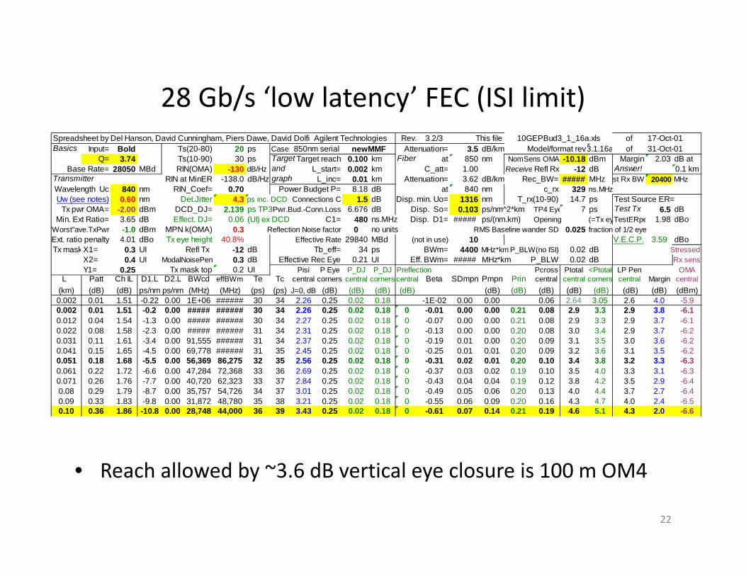
28 Gb/s ‘low latency’ FEC (ISI limit)
• Reach allowed by ~3.6 dB vertical eye closure is 100 m OM4
22
Spreadsheet by Del Hanson, David Cunningham, Piers Dawe, David Dolfi Agilent Technologies Rev. 3.2/3 This file ofBasics Input= Bold Ts(20-80) 20 ps Case: Attenuation= 3.5 dB/km Model/format rev3.1.16a of
Q= 3.74 Ts(10-90) 30 ps Target Target reach 0.100 km Fiber at 850 nm NomSens OMA -10.18 dBm Margin 2.03 dB atBase Rate= 28050 MBd RIN(OMA) -130 dB/Hz and L_start= 0.002 km C_att= 1.00 Receive Refl Rx -12 dB Answer! 0.1 km
Transmitter RIN at MinER -138.0 dB/Hz graph L_inc= 0.01 km Attenuation= 3.62 dB/km Rec_BW= ##### MHz st Rx BW 20400 MHzWavelength Uc 840 nm RIN_Coef= 0.70 Power Budget P= 8.18 dB at 840 nm c_rx 329 ns.MHzUw (see notes) 0.60 nm Det.Jitter 4.3 ps inc. DCD Connections C 1.5 dB Disp. min. Uo= 1316 nm T_rx(10-90) 14.7 ps Test Source ER=
Tx pwr OMA= -2.00 dBm DCD_DJ= 2.139 ps TP3Pwr.Bud.-Conn.Loss 6.676 dB Disp. So= 0.103 ps/nm^2*km TP4 Eye 7 ps Test Tx 6.5 dBMin. Ext Ratio= 3.65 dB Effect. DJ= 0.06 (UI) ex DCD C1= 480 ns.MHz Disp. D1= ##### ps/(nm.km) Opening (=Tx eyTestERpe 1.98 dBo
"Worst"ave.TxPwr -1.0 dBm MPN k(OMA) 0.3 Reflection Noise factor 0 no units RMS Baseline wander SD 0.025 fraction of 1/2 eyeExt. ratio penalty 4.01 dBo Tx eye height 40.8% Effective Rate 29840 MBd (not in use) 10 V.E.C.P. 3.59 dBoTx maskX1= 0.3 UI Refl Tx -12 dB Tb_eff= 34 ps BWm= 4400 MHz*km P_BLW(no ISI) 0.02 dB Stressed
X2= 0.4 UI ModalNoisePen 0.3 dB Effective Rec Eye 0.21 UI Eff. BWm= ##### MHz*km P_BLW 0.02 dB Rx sensY1= 0.25 Tx mask top 0.2 UI Pisi P Eye P_DJ P_DJ Preflection Pcross Ptotal <Ptotal LP Pen OMA
L Patt Ch IL D1.L D2.L BWcd effBWm Te Tc central corners central corners central Beta SDmpn Pmpn Prin central central corners central Margin central(km) (dB) (dB) ps/nm ps/nm (MHz) (MHz) (ps) (ps) J=0, dB (dB) (dB) (dB) (dB) (dB) (dB) (dB) (dB) (dB) (dB) (dB) (dBm)0.002 0.01 1.51 -0.22 0.00 1E+06 ###### 30 34 2.26 0.25 0.02 0.18 -1E-02 0.00 0.00 0.06 2.64 3.05 2.6 4.0 -5.90.002 0.01 1.51 -0.2 0.00 ##### ###### 30 34 2.26 0.25 0.02 0.18 0 -0.01 0.00 0.00 0.21 0.08 2.9 3.3 2.9 3.8 -6.10.012 0.04 1.54 -1.3 0.00 ##### ###### 30 34 2.27 0.25 0.02 0.18 0 -0.07 0.00 0.00 0.21 0.08 2.9 3.3 2.9 3.7 -6.10.022 0.08 1.58 -2.3 0.00 ##### ###### 31 34 2.31 0.25 0.02 0.18 0 -0.13 0.00 0.00 0.20 0.08 3.0 3.4 2.9 3.7 -6.20.031 0.11 1.61 -3.4 0.00 91,555 ###### 31 34 2.37 0.25 0.02 0.18 0 -0.19 0.01 0.00 0.20 0.09 3.1 3.5 3.0 3.6 -6.20.041 0.15 1.65 -4.5 0.00 69,778 ###### 31 35 2.45 0.25 0.02 0.18 0 -0.25 0.01 0.01 0.20 0.09 3.2 3.6 3.1 3.5 -6.20.051 0.18 1.68 -5.5 0.00 56,369 86,275 32 35 2.56 0.25 0.02 0.18 0 -0.31 0.02 0.01 0.20 0.10 3.4 3.8 3.2 3.3 -6.30.061 0.22 1.72 -6.6 0.00 47,284 72,368 33 36 2.69 0.25 0.02 0.18 0 -0.37 0.03 0.02 0.19 0.10 3.5 4.0 3.3 3.1 -6.30.071 0.26 1.76 -7.7 0.00 40,720 62,323 33 37 2.84 0.25 0.02 0.18 0 -0.43 0.04 0.04 0.19 0.12 3.8 4.2 3.5 2.9 -6.40.08 0.29 1.79 -8.7 0.00 35,757 54,726 34 37 3.01 0.25 0.02 0.18 0 -0.49 0.05 0.06 0.20 0.13 4.0 4.4 3.7 2.7 -6.40.09 0.33 1.83 -9.8 0.00 31,872 48,780 35 38 3.21 0.25 0.02 0.18 0 -0.55 0.06 0.09 0.20 0.16 4.3 4.7 4.0 2.4 -6.50.10 0.36 1.86 -10.8 0.00 28,748 44,000 36 39 3.43 0.25 0.02 0.18 0 -0.61 0.07 0.14 0.21 0.19 4.6 5.1 4.3 2.0 -6.6
17-Oct-0110GEPBud3_1_16a.xls850nm serial newMMF 31-Oct-01

• Link models for 16ps rise/fall time
23

25.8 Gb/s no FEC (power budget limit)
• Reach allowed by power budget is 100 m OM4– ~2.2 dB vertical eye closure penalty
24
Spreadsheet by Del Hanson, David Cunningham, Piers Dawe, David Dolfi Agilent Technologies Rev. 3.2/3 This file ofBasics Input= Bold Ts(20-80) 16 ps Case: Attenuation= 3.5 dB/km Model/format rev3.1.16a of
Q= 7.04 Ts(10-90) 24 ps Target Target reach 0.100 km Fiber at 850 nm NomSens OMA -7.61 dBm Margin 0.13 dB atBase Rate= 25781 MBd RIN(OMA) -130 dB/Hz and L_start= 0.002 km C_att= 1.00 Receive Refl Rx -12 dB Answer! 0.1 km
Transmitter RIN at MinER -138.0 dB/Hz graph L_inc= 0.01 km Attenuation= 3.62 dB/km Rec_BW= ##### MHz st Rx BW 18750 MHzWavelength Uc 840 nm RIN_Coef= 0.70 Power Budget P= 5.61 dB at 840 nm c_rx 329 ns.MHzUw (see notes) 0.60 nm Det.Jitter 4.7 ps inc. DCD Connections C 1.5 dB Disp. min. Uo= 1316 nm T_rx(10-90) 16.0 ps Test Source ER=
Tx pwr OMA= -2.00 dBm DCD_DJ= 2.3273 ps TP3Pwr.Bud.-Conn.Loss 4.11 dB Disp. So= 0.103 ps/nm^2*km TP4 Eye 8 ps Test Tx 6.5 dBMin. Ext Ratio= 3.65 dB Effect. DJ= 0.06 (UI) ex DCD C1= 480 ns.MHz Disp. D1= ##### ps/(nm.km) Opening (=Tx eyTestERpe 1.98 dBo
"Worst"ave.TxPwr -1.0 dBm MPN k(OMA) 0.3 Reflection Noise factor 0 no units RMS Baseline wander SD 0.025 fraction of 1/2 eyeExt. ratio penalty 4.01 dBo Tx eye height 58.4% Effective Rate 27427 MBd (not in use) 10 V.E.C.P. 2.16 dBoTx maskX1= 0.3 UI Refl Tx -12 dB Tb_eff= 36 ps BWm= 4400 MHz*km P_BLW(no ISI) 0.07 dB Stressed
X2= 0.4 UI ModalNoisePen 0.3 dB Effective Rec Eye 0.21 UI Eff. BWm= ##### MHz*km P_BLW 0.07 dB Rx sensY1= 0.25 Tx mask top 0.2 UI Pisi P Eye P_DJ P_DJ Preflection Pcross Ptotal <Ptotal LP Pen OMA
L Patt Ch IL D1.L D2.L BWcd effBWm Te Tc central corners central corners central Beta SDmpn Pmpn Prin central central corners central Margin central(km) (dB) (dB) ps/nm ps/nm (MHz) (MHz) (ps) (ps) J=0, dB (dB) (dB) (dB) (dB) (dB) (dB) (dB) (dB) (dB) (dB) (dB) (dBm)0.002 0.01 1.51 -0.22 0.00 1E+06 ###### 24 29 1.06 0.23 0.02 0.17 -1E-02 0.00 0.00 0.09 1.47 1.85 1.5 2.6 -4.00.002 0.01 1.51 -0.2 0.00 ##### ###### 24 29 1.06 0.23 0.02 0.17 0 -0.01 0.00 0.00 0.40 0.16 1.9 2.3 1.9 2.2 -4.40.012 0.04 1.54 -1.3 0.00 ##### ###### 24 29 1.07 0.23 0.02 0.17 0 -0.07 0.00 0.00 0.40 0.16 2.0 2.4 2.0 2.1 -4.50.022 0.08 1.58 -2.3 0.00 ##### ###### 25 29 1.10 0.23 0.02 0.17 0 -0.12 0.00 0.00 0.40 0.16 2.1 2.4 2.0 2.1 -4.50.031 0.11 1.61 -3.4 0.00 91,555 ###### 25 30 1.15 0.24 0.02 0.17 0 -0.18 0.01 0.00 0.39 0.16 2.1 2.5 2.0 2.0 -4.50.041 0.15 1.65 -4.5 0.00 69,778 ###### 26 30 1.21 0.24 0.02 0.17 0 -0.23 0.01 0.01 0.39 0.17 2.3 2.6 2.1 1.9 -4.60.051 0.18 1.68 -5.5 0.00 56,369 86,275 26 31 1.30 0.24 0.02 0.17 0 -0.29 0.02 0.03 0.38 0.19 2.4 2.8 2.2 1.7 -4.60.061 0.22 1.72 -6.6 0.00 47,284 72,368 27 31 1.40 0.24 0.02 0.17 0 -0.34 0.02 0.06 0.38 0.21 2.6 3.0 2.4 1.5 -4.70.071 0.26 1.76 -7.7 0.00 40,720 62,323 28 32 1.52 0.24 0.02 0.17 0 -0.40 0.03 0.10 0.37 0.25 2.8 3.2 2.6 1.3 -4.80.08 0.29 1.79 -8.7 0.00 35,757 54,726 29 33 1.66 0.24 0.02 0.17 0 -0.45 0.04 0.17 0.38 0.31 3.1 3.5 2.8 1.0 -4.90.09 0.33 1.83 -9.8 0.00 31,872 48,780 30 34 1.83 0.24 0.02 0.17 0 -0.51 0.05 0.26 0.38 0.39 3.5 3.9 3.2 0.6 -5.10.10 0.36 1.86 -10.8 0.00 28,748 44,000 31 35 2.01 0.25 0.02 0.18 0 -0.56 0.06 0.38 0.39 0.51 4.0 4.4 3.6 0.1 -5.3
17-Oct-0110GEPBud3_1_16a.xls850nm serial newMMF 31-Oct-01

25.8 Gb/s ‘high latency’ FEC (power budget limit)
• Reach allowed by power budget is 170 m OM4– ~4.0 dB VECP (too high)
25
Spreadsheet by Del Hanson, David Cunningham, Piers Dawe, David Dolfi Agilent Technologies Rev. 3.2/3 This file ofBasics Input= Bold Ts(20-80) 16 ps Case: Attenuation= 3.5 dB/km Model/format rev3.1.16a of
Q= 4.04 Ts(10-90) 24 ps Target Target reach 0.170 km Fiber at 850 nm NomSens OMA -10.02 dBm Margin 0.34 dB atBase Rate= 25781 MBd RIN(OMA) -130 dB/Hz and L_start= 0.002 km C_att= 1.00 Receive Refl Rx -12 dB Answer! 0.17 km
Transmitter RIN at MinER -138.0 dB/Hz graph L_inc= 0.017 km Attenuation= 3.62 dB/km Rec_BW= ##### MHz st Rx BW 18750 MHzWavelength Uc 840 nm RIN_Coef= 0.70 Power Budget P= 8.02 dB at 840 nm c_rx 329 ns.MHzUw (see notes) 0.60 nm Det.Jitter 4.7 ps inc. DCD Connections C 1.5 dB Disp. min. Uo= 1316 nm T_rx(10-90) 16.0 ps Test Source ER=
Tx pwr OMA= -2.00 dBm DCD_DJ= 2.3273 ps TP3Pwr.Bud.-Conn.Loss 6.524 dB Disp. So= 0.103 ps/nm^2*km TP4 Eye 8 ps Test Tx 6.5 dBMin. Ext Ratio= 3.65 dB Effect. DJ= 0.06 (UI) ex DCD C1= 480 ns.MHz Disp. D1= ##### ps/(nm.km) Opening (=Tx eyTestERpe 1.98 dBo
"Worst"ave.TxPwr -1.0 dBm MPN k(OMA) 0.3 Reflection Noise factor 0 no units RMS Baseline wander SD 0.025 fraction of 1/2 eyeExt. ratio penalty 4.01 dBo Tx eye height 58.4% Effective Rate 27427 MBd (not in use) 10 V.E.C.P. 4.04 dBoTx maskX1= 0.3 UI Refl Tx -12 dB Tb_eff= 36 ps BWm= 4400 MHz*km P_BLW(no ISI) 0.02 dB Stressed
X2= 0.4 UI ModalNoisePen 0.3 dB Effective Rec Eye 0.21 UI Eff. BWm= ##### MHz*km P_BLW 0.02 dB Rx sensY1= 0.25 Tx mask top 0.2 UI Pisi P Eye P_DJ P_DJ Preflection Pcross Ptotal <Ptotal LP Pen OMA
L Patt Ch IL D1.L D2.L BWcd effBWm Te Tc central corners central corners central Beta SDmpn Pmpn Prin central central corners central Margin central(km) (dB) (dB) ps/nm ps/nm (MHz) (MHz) (ps) (ps) J=0, dB (dB) (dB) (dB) (dB) (dB) (dB) (dB) (dB) (dB) (dB) (dB) (dBm)0.002 0.01 1.51 -0.22 0.00 1E+06 ###### 24 29 1.06 0.23 0.02 0.17 -1E-02 0.00 0.00 0.03 1.41 1.79 1.4 5.1 -4.20.002 0.01 1.51 -0.2 0.00 ##### ###### 24 29 1.06 0.23 0.02 0.17 0 -0.01 0.00 0.00 0.12 0.04 1.5 1.9 1.5 5.0 -4.30.019 0.07 1.57 -2.0 0.00 ##### ###### 25 29 1.09 0.23 0.02 0.17 0 -0.11 0.00 0.00 0.12 0.04 1.6 2.0 1.6 4.9 -4.40.036 0.13 1.63 -3.9 0.00 80,754 ###### 25 30 1.17 0.24 0.02 0.17 0 -0.20 0.01 0.00 0.12 0.04 1.8 2.2 1.7 4.7 -4.40.052 0.19 1.69 -5.7 0.00 54,863 83,969 26 31 1.31 0.24 0.02 0.17 0 -0.29 0.02 0.01 0.12 0.05 2.0 2.4 1.8 4.5 -4.50.069 0.25 1.75 -7.5 0.00 41,544 63,584 28 32 1.50 0.24 0.02 0.17 0 -0.39 0.03 0.03 0.12 0.06 2.3 2.7 2.0 4.2 -4.60.086 0.31 1.81 -9.3 0.00 33,428 51,163 30 34 1.75 0.24 0.02 0.17 0 -0.48 0.04 0.07 0.12 0.08 2.6 3.0 2.3 3.9 -4.70.103 0.37 1.87 -11.1 0.00 27,965 42,802 32 36 2.06 0.25 0.02 0.18 0 -0.58 0.06 0.13 0.12 0.10 3.1 3.5 2.7 3.4 -4.80.12 0.43 1.93 -13.0 0.01 24,037 36,789 34 38 2.42 0.25 0.02 0.18 0 -0.67 0.08 0.22 0.13 0.15 3.7 4.1 3.2 2.8 -5.00.136 0.49 1.99 -14.8 0.01 21,077 32,258 36 40 2.85 0.25 0.02 0.18 0 -0.76 0.09 0.34 0.15 0.22 4.4 4.8 3.9 2.2 -5.20.153 0.55 2.05 -16.6 0.01 18,765 28,721 39 42 3.33 0.25 0.02 0.18 0 -0.86 0.11 0.48 0.17 0.33 5.2 5.6 4.6 1.3 -5.50.17 0.62 2.12 -18.4 0.01 16,911 25,882 42 45 3.88 0.26 0.02 0.19 0 -0.95 0.13 0.66 0.20 0.50 6.2 6.6 5.6 0.3 -5.9
17-Oct-0110GEPBud3_1_16a.xls850nm serial newMMF 31-Oct-01

25.8 Gb/s ‘high latency’ FEC (ISI limit)
• Reach allowed by 3.6 dB vertical eye closure is 155 m OM4
26
Spreadsheet by Del Hanson, David Cunningham, Piers Dawe, David Dolfi Agilent Technologies Rev. 3.2/3 This file ofBasics Input= Bold Ts(20-80) 16 ps Case: Attenuation= 3.5 dB/km Model/format rev3.1.16a of
Q= 4.04 Ts(10-90) 24 ps Target Target reach 0.155 km Fiber at 850 nm NomSens OMA -10.02 dBm Margin 1.24 dB atBase Rate= 25781 MBd RIN(OMA) -130 dB/Hz and L_start= 0.002 km C_att= 1.00 Receive Refl Rx -12 dB Answer! 0.155 km
Transmitter RIN at MinER -138.0 dB/Hz graph L_inc= 0.015 km Attenuation= 3.62 dB/km Rec_BW= ##### MHz st Rx BW 18750 MHzWavelength Uc 840 nm RIN_Coef= 0.70 Power Budget P= 8.02 dB at 840 nm c_rx 329 ns.MHzUw (see notes) 0.60 nm Det.Jitter 4.7 ps inc. DCD Connections C 1.5 dB Disp. min. Uo= 1316 nm T_rx(10-90) 16.0 ps Test Source ER=
Tx pwr OMA= -2.00 dBm DCD_DJ= 2.3273 ps TP3Pwr.Bud.-Conn.Loss 6.524 dB Disp. So= 0.103 ps/nm^2*km TP4 Eye 8 ps Test Tx 6.5 dBMin. Ext Ratio= 3.65 dB Effect. DJ= 0.06 (UI) ex DCD C1= 480 ns.MHz Disp. D1= ##### ps/(nm.km) Opening (=Tx eyTestERpe 1.98 dBo
"Worst"ave.TxPwr -1.0 dBm MPN k(OMA) 0.3 Reflection Noise factor 0 no units RMS Baseline wander SD 0.025 fraction of 1/2 eyeExt. ratio penalty 4.01 dBo Tx eye height 58.4% Effective Rate 27427 MBd (not in use) 10 V.E.C.P. 3.54 dBoTx maskX1= 0.3 UI Refl Tx -12 dB Tb_eff= 36 ps BWm= 4400 MHz*km P_BLW(no ISI) 0.02 dB Stressed
X2= 0.4 UI ModalNoisePen 0.3 dB Effective Rec Eye 0.21 UI Eff. BWm= ##### MHz*km P_BLW 0.02 dB Rx sensY1= 0.25 Tx mask top 0.2 UI Pisi P Eye P_DJ P_DJ Preflection Pcross Ptotal <Ptotal LP Pen OMA
L Patt Ch IL D1.L D2.L BWcd effBWm Te Tc central corners central corners central Beta SDmpn Pmpn Prin central central corners central Margin central(km) (dB) (dB) ps/nm ps/nm (MHz) (MHz) (ps) (ps) J=0, dB (dB) (dB) (dB) (dB) (dB) (dB) (dB) (dB) (dB) (dB) (dB) (dBm)0.002 0.01 1.51 -0.22 0.00 1E+06 ###### 24 29 1.06 0.23 0.02 0.17 -1E-02 0.00 0.00 0.03 1.41 1.79 1.4 5.1 -5.10.002 0.01 1.51 -0.2 0.00 ##### ###### 24 29 1.06 0.23 0.02 0.17 0 -0.01 0.00 0.00 0.12 0.04 1.5 1.9 1.5 5.0 -5.20.017 0.06 1.56 -1.9 0.00 ##### ###### 25 29 1.08 0.23 0.02 0.17 0 -0.10 0.00 0.00 0.12 0.04 1.6 2.0 1.6 4.9 -5.20.033 0.12 1.62 -3.5 0.00 88,185 ###### 25 30 1.15 0.24 0.02 0.17 0 -0.18 0.01 0.00 0.12 0.04 1.8 2.1 1.6 4.8 -5.30.048 0.17 1.67 -5.2 0.00 60,018 91,858 26 31 1.27 0.24 0.02 0.17 0 -0.27 0.01 0.01 0.12 0.05 1.9 2.3 1.8 4.6 -5.40.063 0.23 1.73 -6.9 0.00 45,488 69,620 27 32 1.43 0.24 0.02 0.17 0 -0.35 0.02 0.02 0.12 0.05 2.2 2.6 1.9 4.4 -5.40.079 0.28 1.78 -8.5 0.00 36,622 56,051 29 33 1.64 0.24 0.02 0.17 0 -0.44 0.04 0.05 0.12 0.07 2.5 2.9 2.2 4.0 -5.50.094 0.34 1.84 -10.2 0.00 30,649 46,908 31 35 1.89 0.24 0.02 0.17 0 -0.53 0.05 0.09 0.12 0.09 2.9 3.2 2.5 3.7 -5.60.109 0.40 1.90 -11.8 0.00 26,351 40,330 33 36 2.19 0.25 0.02 0.18 0 -0.61 0.07 0.16 0.13 0.12 3.3 3.7 2.9 3.2 -5.80.124 0.45 1.95 -13.5 0.01 23,110 35,370 35 38 2.54 0.25 0.02 0.18 0 -0.70 0.08 0.25 0.13 0.17 3.9 4.3 3.4 2.7 -6.00.14 0.51 2.01 -15.1 0.01 20,579 31,496 37 40 2.94 0.25 0.02 0.18 0 -0.78 0.10 0.36 0.15 0.24 4.5 4.9 4.0 2.0 -6.20.155 0.56 2.06 -16.8 0.01 18,547 28,387 39 42 3.39 0.25 0.02 0.18 0 -0.87 0.11 0.50 0.17 0.34 5.3 5.7 4.7 1.2 -6.4
17-Oct-0110GEPBud3_1_16a.xls850nm serial newMMF 31-Oct-01

25.8 Gb/s ‘high latency’ FEC (ISI limit)
• Reach allowed by 3.0 dB vertical eye closure is 135 m OM4
27
Spreadsheet by Del Hanson, David Cunningham, Piers Dawe, David Dolfi Agilent Technologies Rev. 3.2/3 This file ofBasics Input= Bold Ts(20-80) 16 ps Case: Attenuation= 3.5 dB/km Model/format rev3.1.16a of
Q= 4.04 Ts(10-90) 24 ps Target Target reach 0.135 km Fiber at 850 nm NomSens OMA -10.02 dBm Margin 2.22 dB atBase Rate= 25781 MBd RIN(OMA) -130 dB/Hz and L_start= 0.002 km C_att= 1.00 Receive Refl Rx -12 dB Answer! 0.135 km
Transmitter RIN at MinER -138.0 dB/Hz graph L_inc= 0.013 km Attenuation= 3.62 dB/km Rec_BW= ##### MHz st Rx BW 18750 MHzWavelength Uc 840 nm RIN_Coef= 0.70 Power Budget P= 8.02 dB at 840 nm c_rx 329 ns.MHzUw (see notes) 0.60 nm Det.Jitter 4.7 ps inc. DCD Connections C 1.5 dB Disp. min. Uo= 1316 nm T_rx(10-90) 16.0 ps Test Source ER=
Tx pwr OMA= -2.00 dBm DCD_DJ= 2.3273 ps TP3Pwr.Bud.-Conn.Loss 6.524 dB Disp. So= 0.103 ps/nm^2*km TP4 Eye 8 ps Test Tx 6.5 dBMin. Ext Ratio= 3.65 dB Effect. DJ= 0.06 (UI) ex DCD C1= 480 ns.MHz Disp. D1= ##### ps/(nm.km) Opening (=Tx eyTestERpe 1.98 dBo
"Worst"ave.TxPwr -1.0 dBm MPN k(OMA) 0.3 Reflection Noise factor 0 no units RMS Baseline wander SD 0.025 fraction of 1/2 eyeExt. ratio penalty 4.01 dBo Tx eye height 58.4% Effective Rate 27427 MBd (not in use) 10 V.E.C.P. 2.97 dBoTx maskX1= 0.3 UI Refl Tx -12 dB Tb_eff= 36 ps BWm= 4400 MHz*km P_BLW(no ISI) 0.02 dB Stressed
X2= 0.4 UI ModalNoisePen 0.3 dB Effective Rec Eye 0.21 UI Eff. BWm= ##### MHz*km P_BLW 0.02 dB Rx sensY1= 0.25 Tx mask top 0.2 UI Pisi P Eye P_DJ P_DJ Preflection Pcross Ptotal <Ptotal LP Pen OMA
L Patt Ch IL D1.L D2.L BWcd effBWm Te Tc central corners central corners central Beta SDmpn Pmpn Prin central central corners central Margin central(km) (dB) (dB) ps/nm ps/nm (MHz) (MHz) (ps) (ps) J=0, dB (dB) (dB) (dB) (dB) (dB) (dB) (dB) (dB) (dB) (dB) (dB) (dBm)0.002 0.01 1.51 -0.22 0.00 1E+06 ###### 24 29 1.06 0.23 0.02 0.17 -1E-02 0.00 0.00 0.03 1.41 1.79 1.4 5.1 -6.00.002 0.01 1.51 -0.2 0.00 ##### ###### 24 29 1.06 0.23 0.02 0.17 0 -0.01 0.00 0.00 0.12 0.04 1.5 1.9 1.5 5.0 -6.20.015 0.06 1.56 -1.7 0.00 ##### ###### 24 29 1.08 0.23 0.02 0.17 0 -0.09 0.00 0.00 0.12 0.04 1.6 2.0 1.6 4.9 -6.20.029 0.10 1.60 -3.1 0.00 ##### ###### 25 30 1.13 0.24 0.02 0.17 0 -0.16 0.01 0.00 0.12 0.04 1.7 2.1 1.6 4.8 -6.30.042 0.15 1.65 -4.5 0.00 68,612 ###### 26 30 1.22 0.24 0.02 0.17 0 -0.23 0.01 0.00 0.12 0.04 1.9 2.2 1.7 4.7 -6.30.055 0.20 1.70 -6.0 0.00 52,080 79,710 27 31 1.34 0.24 0.02 0.17 0 -0.31 0.02 0.01 0.12 0.05 2.0 2.4 1.8 4.5 -6.40.069 0.25 1.75 -7.4 0.00 41,968 64,234 28 32 1.50 0.24 0.02 0.17 0 -0.38 0.03 0.03 0.12 0.06 2.3 2.7 2.0 4.3 -6.40.082 0.30 1.80 -8.9 0.00 35,145 53,790 29 33 1.69 0.24 0.02 0.17 0 -0.46 0.04 0.06 0.12 0.07 2.5 2.9 2.3 4.0 -6.50.095 0.34 1.84 -10.3 0.00 30,230 46,267 31 35 1.91 0.25 0.02 0.18 0 -0.53 0.05 0.10 0.12 0.09 2.9 3.3 2.5 3.6 -6.60.108 0.39 1.89 -11.8 0.00 26,521 40,590 33 36 2.18 0.25 0.02 0.18 0 -0.61 0.07 0.16 0.12 0.12 3.3 3.7 2.9 3.2 -6.80.122 0.44 1.94 -13.2 0.01 23,622 36,154 34 38 2.47 0.25 0.02 0.18 0 -0.68 0.08 0.23 0.13 0.16 3.8 4.2 3.3 2.8 -6.90.135 0.49 1.99 -14.6 0.01 21,295 32,593 36 40 2.81 0.25 0.02 0.18 0 -0.76 0.09 0.33 0.14 0.21 4.3 4.7 3.8 2.2 -7.1
17-Oct-0110GEPBud3_1_16a.xls850nm serial newMMF 31-Oct-01
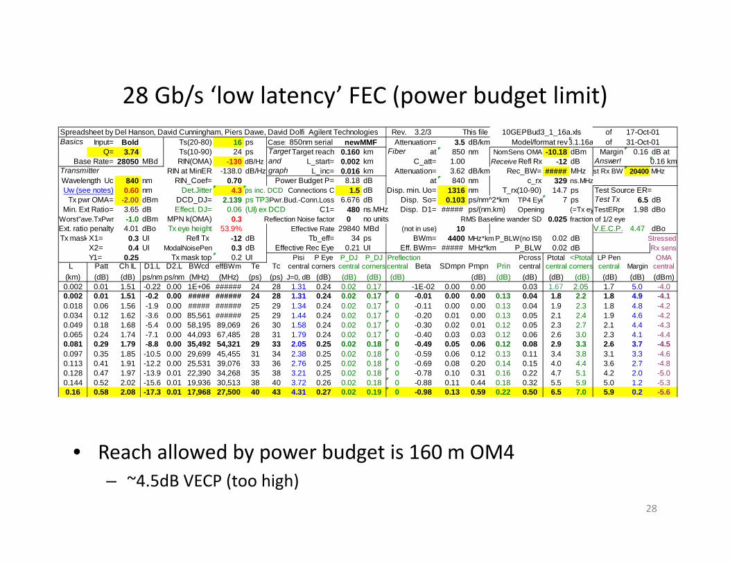
28 Gb/s ‘low latency’ FEC (power budget limit)
• Reach allowed by power budget is 160 m OM4– ~4.5dB VECP (too high)
28
Spreadsheet by Del Hanson, David Cunningham, Piers Dawe, David Dolfi Agilent Technologies Rev. 3.2/3 This file ofBasics Input= Bold Ts(20-80) 16 ps Case: Attenuation= 3.5 dB/km Model/format rev3.1.16a of
Q= 3.74 Ts(10-90) 24 ps Target Target reach 0.160 km Fiber at 850 nm NomSens OMA -10.18 dBm Margin 0.16 dB atBase Rate= 28050 MBd RIN(OMA) -130 dB/Hz and L_start= 0.002 km C_att= 1.00 Receive Refl Rx -12 dB Answer! 0.16 km
Transmitter RIN at MinER -138.0 dB/Hz graph L_inc= 0.016 km Attenuation= 3.62 dB/km Rec_BW= ##### MHz st Rx BW 20400 MHzWavelength Uc 840 nm RIN_Coef= 0.70 Power Budget P= 8.18 dB at 840 nm c_rx 329 ns.MHzUw (see notes) 0.60 nm Det.Jitter 4.3 ps inc. DCD Connections C 1.5 dB Disp. min. Uo= 1316 nm T_rx(10-90) 14.7 ps Test Source ER=
Tx pwr OMA= -2.00 dBm DCD_DJ= 2.139 ps TP3Pwr.Bud.-Conn.Loss 6.676 dB Disp. So= 0.103 ps/nm^2*km TP4 Eye 7 ps Test Tx 6.5 dBMin. Ext Ratio= 3.65 dB Effect. DJ= 0.06 (UI) ex DCD C1= 480 ns.MHz Disp. D1= ##### ps/(nm.km) Opening (=Tx eyTestERpe 1.98 dBo
"Worst"ave.TxPwr -1.0 dBm MPN k(OMA) 0.3 Reflection Noise factor 0 no units RMS Baseline wander SD 0.025 fraction of 1/2 eyeExt. ratio penalty 4.01 dBo Tx eye height 53.9% Effective Rate 29840 MBd (not in use) 10 V.E.C.P. 4.47 dBoTx maskX1= 0.3 UI Refl Tx -12 dB Tb_eff= 34 ps BWm= 4400 MHz*km P_BLW(no ISI) 0.02 dB Stressed
X2= 0.4 UI ModalNoisePen 0.3 dB Effective Rec Eye 0.21 UI Eff. BWm= ##### MHz*km P_BLW 0.02 dB Rx sensY1= 0.25 Tx mask top 0.2 UI Pisi P Eye P_DJ P_DJ Preflection Pcross Ptotal <Ptotal LP Pen OMA
L Patt Ch IL D1.L D2.L BWcd effBWm Te Tc central corners central corners central Beta SDmpn Pmpn Prin central central corners central Margin central(km) (dB) (dB) ps/nm ps/nm (MHz) (MHz) (ps) (ps) J=0, dB (dB) (dB) (dB) (dB) (dB) (dB) (dB) (dB) (dB) (dB) (dB) (dBm)0.002 0.01 1.51 -0.22 0.00 1E+06 ###### 24 28 1.31 0.24 0.02 0.17 -1E-02 0.00 0.00 0.03 1.67 2.05 1.7 5.0 -4.00.002 0.01 1.51 -0.2 0.00 ##### ###### 24 28 1.31 0.24 0.02 0.17 0 -0.01 0.00 0.00 0.13 0.04 1.8 2.2 1.8 4.9 -4.10.018 0.06 1.56 -1.9 0.00 ##### ###### 25 29 1.34 0.24 0.02 0.17 0 -0.11 0.00 0.00 0.13 0.04 1.9 2.3 1.8 4.8 -4.20.034 0.12 1.62 -3.6 0.00 85,561 ###### 25 29 1.44 0.24 0.02 0.17 0 -0.20 0.01 0.00 0.13 0.05 2.1 2.4 1.9 4.6 -4.20.049 0.18 1.68 -5.4 0.00 58,195 89,069 26 30 1.58 0.24 0.02 0.17 0 -0.30 0.02 0.01 0.12 0.05 2.3 2.7 2.1 4.4 -4.30.065 0.24 1.74 -7.1 0.00 44,093 67,485 28 31 1.79 0.24 0.02 0.17 0 -0.40 0.03 0.03 0.12 0.06 2.6 3.0 2.3 4.1 -4.40.081 0.29 1.79 -8.8 0.00 35,492 54,321 29 33 2.05 0.25 0.02 0.18 0 -0.49 0.05 0.06 0.12 0.08 2.9 3.3 2.6 3.7 -4.50.097 0.35 1.85 -10.5 0.00 29,699 45,455 31 34 2.38 0.25 0.02 0.18 0 -0.59 0.06 0.12 0.13 0.11 3.4 3.8 3.1 3.3 -4.60.113 0.41 1.91 -12.2 0.00 25,531 39,076 33 36 2.76 0.25 0.02 0.18 0 -0.69 0.08 0.20 0.14 0.15 4.0 4.4 3.6 2.7 -4.80.128 0.47 1.97 -13.9 0.01 22,390 34,268 35 38 3.21 0.25 0.02 0.18 0 -0.78 0.10 0.31 0.16 0.22 4.7 5.1 4.2 2.0 -5.00.144 0.52 2.02 -15.6 0.01 19,936 30,513 38 40 3.72 0.26 0.02 0.18 0 -0.88 0.11 0.44 0.18 0.32 5.5 5.9 5.0 1.2 -5.30.16 0.58 2.08 -17.3 0.01 17,968 27,500 40 43 4.31 0.27 0.02 0.19 0 -0.98 0.13 0.59 0.22 0.50 6.5 7.0 5.9 0.2 -5.6
17-Oct-0110GEPBud3_1_16a.xls850nm serial newMMF 31-Oct-01
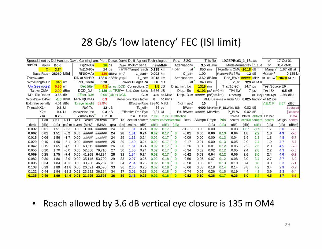
28 Gb/s ‘low latency’ FEC (ISI limit)
• Reach allowed by 3.6 dB vertical eye closure is 135 m OM4
29
Spreadsheet by Del Hanson, David Cunningham, Piers Dawe, David Dolfi Agilent Technologies Rev. 3.2/3 This file ofBasics Input= Bold Ts(20-80) 16 ps Case: Attenuation= 3.5 dB/km Model/format rev3.1.16a of
Q= 3.74 Ts(10-90) 24 ps Target Target reach 0.135 km Fiber at 850 nm NomSens OMA -10.18 dBm Margin 1.67 dB atBase Rate= 28050 MBd RIN(OMA) -130 dB/Hz and L_start= 0.002 km C_att= 1.00 Receive Refl Rx -12 dB Answer! 0.135 km
Transmitter RIN at MinER -138.0 dB/Hz graph L_inc= 0.013 km Attenuation= 3.62 dB/km Rec_BW= ##### MHz st Rx BW 20400 MHzWavelength Uc 840 nm RIN_Coef= 0.70 Power Budget P= 8.18 dB at 840 nm c_rx 329 ns.MHzUw (see notes) 0.60 nm Det.Jitter 4.3 ps inc. DCD Connections C 1.5 dB Disp. min. Uo= 1316 nm T_rx(10-90) 14.7 ps Test Source ER=
Tx pwr OMA= -2.00 dBm DCD_DJ= 2.139 ps TP3Pwr.Bud.-Conn.Loss 6.676 dB Disp. So= 0.103 ps/nm^2*km TP4 Eye 7 ps Test Tx 6.5 dBMin. Ext Ratio= 3.65 dB Effect. DJ= 0.06 (UI) ex DCD C1= 480 ns.MHz Disp. D1= ##### ps/(nm.km) Opening (=Tx eyTestERpe 1.98 dBo
"Worst"ave.TxPwr -1.0 dBm MPN k(OMA) 0.3 Reflection Noise factor 0 no units RMS Baseline wander SD 0.025 fraction of 1/2 eyeExt. ratio penalty 4.01 dBo Tx eye height 53.9% Effective Rate 29840 MBd (not in use) 10 V.E.C.P. 3.57 dBoTx maskX1= 0.3 UI Refl Tx -12 dB Tb_eff= 34 ps BWm= 4400 MHz*km P_BLW(no ISI) 0.02 dB Stressed
X2= 0.4 UI ModalNoisePen 0.3 dB Effective Rec Eye 0.21 UI Eff. BWm= ##### MHz*km P_BLW 0.02 dB Rx sensY1= 0.25 Tx mask top 0.2 UI Pisi P Eye P_DJ P_DJ Preflection Pcross Ptotal <Ptotal LP Pen OMA
L Patt Ch IL D1.L D2.L BWcd effBWm Te Tc central corners central corners central Beta SDmpn Pmpn Prin central central corners central Margin central(km) (dB) (dB) ps/nm ps/nm (MHz) (MHz) (ps) (ps) J=0, dB (dB) (dB) (dB) (dB) (dB) (dB) (dB) (dB) (dB) (dB) (dB) (dBm)0.002 0.01 1.51 -0.22 0.00 1E+06 ###### 24 28 1.31 0.24 0.02 0.17 -1E-02 0.00 0.00 0.03 1.67 2.05 1.7 5.0 -5.50.002 0.01 1.51 -0.2 0.00 ##### ###### 24 28 1.31 0.24 0.02 0.17 0 -0.01 0.00 0.00 0.13 0.04 1.8 2.2 1.8 4.9 -5.60.015 0.06 1.56 -1.7 0.00 ##### ###### 24 29 1.33 0.24 0.02 0.17 0 -0.09 0.00 0.00 0.13 0.04 1.9 2.3 1.8 4.8 -5.70.029 0.10 1.60 -3.1 0.00 ##### ###### 25 29 1.40 0.24 0.02 0.17 0 -0.17 0.01 0.00 0.13 0.05 2.0 2.4 1.9 4.7 -5.70.042 0.15 1.65 -4.5 0.00 68,612 ###### 26 30 1.51 0.24 0.02 0.17 0 -0.26 0.01 0.01 0.12 0.05 2.2 2.6 2.0 4.5 -5.80.055 0.20 1.70 -6.0 0.00 52,080 79,710 27 30 1.65 0.24 0.02 0.17 0 -0.34 0.02 0.02 0.12 0.05 2.4 2.8 2.2 4.3 -5.80.069 0.25 1.75 -7.4 0.00 41,968 64,234 28 31 1.84 0.24 0.02 0.17 0 -0.42 0.03 0.04 0.12 0.06 2.6 3.0 2.4 4.0 -5.90.082 0.30 1.80 -8.9 0.00 35,145 53,790 29 33 2.07 0.25 0.02 0.18 0 -0.50 0.05 0.07 0.12 0.08 3.0 3.4 2.7 3.7 -6.00.095 0.34 1.84 -10.3 0.00 30,230 46,267 31 34 2.34 0.25 0.02 0.18 0 -0.58 0.06 0.11 0.13 0.10 3.4 3.8 3.0 3.3 -6.10.108 0.39 1.89 -11.8 0.00 26,521 40,590 33 36 2.65 0.25 0.02 0.18 0 -0.66 0.08 0.18 0.14 0.14 3.8 4.2 3.4 2.9 -6.20.122 0.44 1.94 -13.2 0.01 23,622 36,154 34 37 3.01 0.25 0.02 0.18 0 -0.74 0.09 0.26 0.15 0.19 4.4 4.8 3.9 2.3 -6.40.135 0.49 1.99 -14.6 0.01 21,295 32,593 36 39 3.41 0.25 0.02 0.18 0 -0.82 0.10 0.36 0.17 0.26 5.0 5.4 4.5 1.7 -6.6
17-Oct-0110GEPBud3_1_16a.xls850nm serial newMMF 31-Oct-01