mnsis interface manual modbus_rel_7.0 (english - pdf - · pdf filecontent mns is interface...
TRANSCRIPT
MNS iS Motor Control Center Interface Manual Modbus System Release V7.0

MNS is a registered trademark.
Other trademarks and trade names reside with their respective owners.
This document relates to the MNS iS System Release 7.0.
The information in this document is subject to change without notice and should not be construed as a commitment by ABB. ABB assumes no responsibility for any errors that may appear in this document.
In no event shall ABB be liable for direct, indirect, special, incidental, or consequential damages of any nature or kind arising from the use of this document, nor shall ABB be liable for incidental or consequential damages arising from use of any software or hardware described in this document.
This document and parts thereof must not be reproduced or copied without ABB's written permission, and the contents thereof must not be imparted to a third party nor be used for any unauthorized purpose. The software described in this document is furnished under a license and may be used, copied, or disclosed only in accordance with the terms of such license.
All rights reserved.
Copyright © 2012 ABB Automation Products GmbH, Ladenburg, Germany

MNS iS Interface Manual Modbus Content
1TGC910251M0202 – Release V7.0 3
Table of content
General ........................................................................................................................... 5
Target Group ..........................................................................................................................5
Use of Warning, Caution, Information and Tip icon ................................................................5
Terminology ............................................................................................................................6
Related Documentation ........................................................................................................10
MNS iS .........................................................................................................................................10
Modbus additional specifications .................................................................................................10
Related System Version .......................................................................................................10
Document Revision History ..................................................................................................10
Introduction.................................................................................................................. 11
MODBUS Standard ..............................................................................................................11
MNS iS Software Requirements ...........................................................................................11
Basics........................................................................................................................... 12
MODBUS RTU......................................................................................................................12
Interfaces...................................................................................................................... 15
MLink Connections ...............................................................................................................15
MLink Redundancy ...............................................................................................................15
References ...........................................................................................................................15
MODBUS RTU Topology......................................................................................................16
MODBUS RTU Communication Settings..............................................................................20
MODBUS TCP Topology ......................................................................................................21
MODBUS TCP Communication Settings..............................................................................23
Failsafe .................................................................................................................................24
Function Codes ........................................................................................................... 25
Message Format...................................................................................................................25
Function Code 02 - Read Input Status .................................................................................26
Function Code 03 - Read Output Registers..........................................................................26
Function Code 04 - Read Input registers ..............................................................................26
Data Presentation for Function Code 03 and 04...................................................................27
Function Code 06 - Preset Single Register...........................................................................28
Function Code 08 - Diagnostic Loop Back (Serial Line only)................................................28
Function Code 16 - Preset Multiple Registers ......................................................................28
Restrictions ...........................................................................................................................29
Exception Code Handling .....................................................................................................29
Content MNS iS Interface Manual Modbus
4 1TGC910251M0202 – Release V7.0
Data Mapping ............................................................................................................... 30
User Data Map......................................................................................................................30
Default Data Map..................................................................................................................30
Monitoring with Function Code 02 ...............................................................................................31
Monitoring with Function Code 03 and 04 ...................................................................................35
Extended Status description for MControl ...................................................................................37
Control Commands ......................................................................................................................45
Switching Commands ..................................................................................................................46
General Purpose Outputs Commands.........................................................................................48
Redundant MLink MODBUS data ................................................................................................55
Control Access .............................................................................................................................56
Extended Failsafe for Modbus TCP......................................................................................58
Failure examples..........................................................................................................................59
Parametrization of Extended Failsafe in MNavigate....................................................................62
Failsafe Matrix..............................................................................................................................64
Troubleshooting .......................................................................................................... 66
LED - Status Information ......................................................................................................66
Comms check .......................................................................................................................66

MNS iS Interface Manual Modbus Introduction
1TGC910251M0202 – Release V7.0 5
General
Target Group
This document describes communication and control interfaces used in MNS iS.
The manual is primarily intended for those requiring information on accessing information and data provided from MNS iS. Furthermore the document provides information for integration of MNS iS as Fieldbus component into PLC or higher level Process Control Systems to control system and application engineers.
It is assumed that the reader of this manual is familiar with basic terms of Fieldbus and control communication (e.g. basic knowledge about PROFIBUS, Modbus etc.).
Use of Warning, Caution, Information and Tip icon

Introduction MNS iS Interface Manual Modbus
6 1TGC910251M0202 – Release V7.0
Terminology
List of the terms, acronyms, abbreviations and definitions that the document uses.
Abbreviation Term Description
Aspect Object ABB technology. An Aspect Object is a computer representation of a real object such as a pump, a valve, an order or a virtual object such as a service or an object type. An Aspect Object is described by its aspects and is organized in structures.
Alarm Alarm is defined as status transition from any state to abnormal state. Status transition to abnormal state can be data crossing over the pre-defined alarm limit.
Bus Local A Control Access term describing that the MControl accepts its commands from a device on the switchgear control network, e.g. the Web Interface, MView.
COTS Commercial off the shelf
Commercial off the shelf product, term to describe products available on the market, ready to use
DCS Distributed Control System
See also PCS
DTM Device Type Manager
Software module used to manage devices via Fieldbus (e.g. PROFIBUS) using frame application environment (e.g. PactWare, ABB Fieldbus Builder etc.)
Eth. Ethernet Ethernet is a local area network (LAN) technology. The Ethernet standard specifies the physical medium, access control rules and the message frames.
Event An event is a status transition from one state to another. It can be defined as alarm, if the state is defined as abnormal or as warning as a pre-alarm state.
FD Field Device Term for devices connected to the Fieldbus (e.g. motor control units or circuit breaker protection)
GSD file Geräte Stamm Datei (German abbreviation)
A hardware description file for a PROFIBUS-DP or PROFIBUS-DP/V1 slave type
GPS Global Positioning System
System to detect local position, universal time and time zone, GPS technology provides accurate time to a system
Hardware Local A Control Access term describing that the MControl accepts its commands from the Hardwired inputs, when the respective Local control input is set to true.

MNS iS Interface Manual Modbus Introduction
1TGC910251M0202 – Release V7.0 7
Abbreviation Term Description
HMI Human Machine Interface
Generic expression
LVS Low voltage switchgear
A factory built assembly built to conform with IEC 60439-1
MCC Motor Control Centre
Common term for switchgear used for motor control and protection.
MNS Modular Low Voltage Switchgear family from ABB
MNS iS The integrated intelligent switchgear solution from ABB
MStart MFeed MControl MLink MView MNavigate
MNS iS components integrated in the switchgear, see the MNS iS System Guide for technical details
MODBUS Fieldbus communication protocol
MODBUS RTU Fieldbus communication protocol
Motor Starter Consists of motor controller and electrical components to control and protect a motor, part of Motor Control Center
NLS Native Language Support
Providing the ability to change the language of software tools in order to support native languages (English is basis, others are optional)
OPC OLE for Process Control, an industrial standard for exchange of information between components and process control application
PCS Process Control System
High level process control system
PLC Programmable Logic Controller
Low level control unit
PROFIBUS-DP Fieldbus communication protocol with cyclic data transfer (V0).
PROFIBUS-DP/V1 Fieldbus communication protocol, extension of PROFIBUS- DP allowing acyclic data transfer and multi master (V1).

Introduction MNS iS Interface Manual Modbus
8 1TGC910251M0202 – Release V7.0
Abbreviation Term Description
PROFIBUS-DP/V2 Fieldbus communication protocol, extension of PROFIBUS- DP allowing time stamp and communication between master and slave (V2).
PROFINET PROFINET is an open standard for Industrial Ethernet and standardized in IEC 61158 and IEC 61784.
PNIO PROFINET IO PROFINET for decentralized periphery and distributed automation
RCU Remote Control Unit Local control unit with pushbutton and indicator to operate a device (e.g. motor) from field level.
RS232 Standard No. 232 for PC communication, established by EIA (Electronics Industries Association, USA)
RS485 Communication interface standard from EIA (Electronics Industries Association, USA), operating on voltages between 0V and +5V. RS-485 is more noise resistant than RS-232C, handles data transmission over longer distances, and can drive more receivers.
RTC Real Time Clock Integrated clock function in devices used to generate time and date information if a remote clock system is not present
Software Local A Control Access term describing that the MControl accepts its commands from the hardwired inputs as a result of either the PCS or MView passing the Control Access Authority to Soft-Local.
Note: Does not require the hardwired local input to be set to true.
SNTP Simple Network Time Protocol
a protocol used for time synchronization in Control Network through Ethernet
Switchgear Bus Network
Term used to describe the internal switchgear communication network, between MLink and MControl.
TCP/IP Transmission Control Protocol / Internet Protocol
TCP/IP is a high-level connection oriented , reliable, full duplex communication protocol developed for integration of the heterogenous systems.
Trip A consequence of an alarm activated or an external trip command from another device to stop the motor or trip the circuit breaker.

MNS iS Interface Manual Modbus Introduction
1TGC910251M0202 – Release V7.0 9
Abbreviation Term Description
UTC Coordinated Universal Time
Coordinated Universal Time is the international time standard. It is the current term for what was commonly referred to as Greenwich Meridian Time (GMT). Zero (0) hours UTC is midnight in Greenwich England, which lies on the zero longitudinal meridian. Universal time is based on a 24 hour clock.
Warning A warning is defined as status transition from any state to pre-alarm state to inform in advance before an alarm level is reached.
Introduction MNS iS Interface Manual Modbus
10 1TGC910251M0202 – Release V7.0
Related Documentation
MNS iS
1TGC910211 M0201 MNS iS Interface Manual MLink, Release 7.0
1TGC910111 M0201 MNS iS MLink Upgrade Kit Manual
1TGC910221 M0201 MNS iS Interface Manual Web Interface, Release 7.0
1TGC910231 M0201 MNS iS Interface Manual OPC Server, Release 7.0
1TGC910241 M0201 MNS iS Interface Manual Profibus, Release 7.0
1TGC910291 M0201 MNS iS Interface Manual PROFINET IO, Release 7.0
1TGC910281 M0201 MNS iS MControl Interface Manual Profibus Direct, Release 7.0
1TGC910261 M0201 MNS iS Interface Manual Redundancy, Release 7.0
1TGC910271 M0201 MNS iS MConnect Interface Manual, Release 7.0
1TGC910001 B0204 MNS iS System Guide
1TGC910201 M0201 MNS iS Quick Guide Installation and System Setup, Release 7.0
1TGC910090 M0201 MNavigate Help file V7.0
1TGC910018 M0208 MNS iS ATEX – Enhancements for Safety
Modbus additional specifications
[1] Modbus Application Protocol Specification V1.1b – Modbus-IDA 28th December 2006
[2] Modbus Messaging on TCP/IP Implementation Guide 1.0a - Modbus-IDA 4th June 2004
Related System Version
The content of this document is related to MNS iS System Release 7.0.
The described functions are designed but may not be fully implemented in all details. Please refer to the current system guides and release notes regarding possible restrictions.
Document Revision History
Rev. Page Chapter Description of change Date
M0201 Initial document for Release V7.0 July 2012
29 Restrictions Modbus RTU restrictions added
M0202 36 Monitoring Funct. code 03/04
Format of “Thermal image” edited July 2012

MNS iS Interface Manual Modbus Introduction
1TGC910251M0202 – Release V7.0 11
Introduction
MODBUS Standard
MODBUS is a serial data communication protocol and was originally developed as a communication language for MODICON programmable controllers, its rights now reside with the Modbus-IDA organization.
The software on the MLink supports the pure Master-Slave operation as defined in the MODBUS RTU specification. This manual describes the MLink communication with MODBUS protocol in RTU and TCP modes.
The MODBUS communication protocol is implemented within the MLink to enable MNS iS to provide interface possibilities to process control systems or any other external systems that supports MODBUS RTU / TCP protocol handling.
The MODBUS configuration can be used in point to point configuration or in multidrop mode. In Master-Slave MODBUS architecture, the MLink is always used in a slave mode. The master station controls the traffic on the bus, in this case, by PCS or PLC system. The MLink responds to the queries received from master station as per the MODBUS specification.
MNS iS Software Requirements
For full support of MNS iS V7.0 functionality the Modbus interface requires:
MLink image 1TGE131013R0001 or higher
MNavigate Version 7.0 or higher
Basics MNS iS Interface Manual Modbus
12 1TGC910251M0202 – Release V7.0
Basics
MODBUS RTU
Master Slave Query Response Cycle
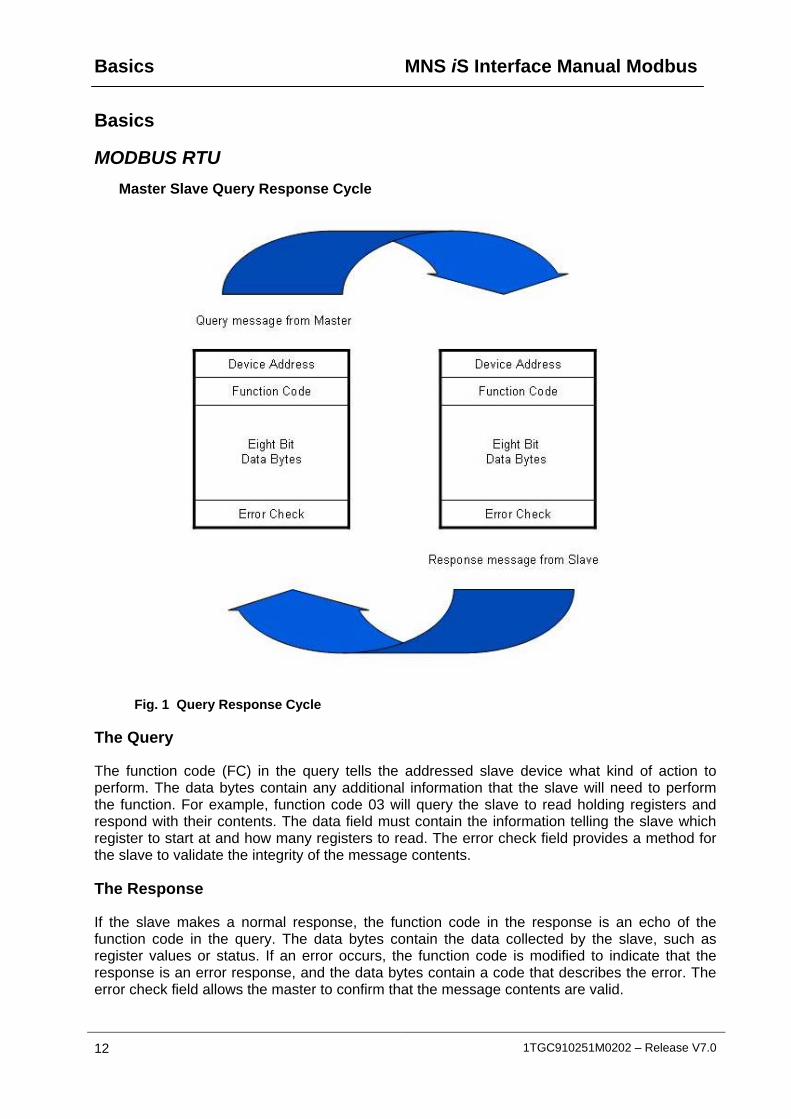
Fig. 1 Query Response Cycle
The Query
The function code (FC) in the query tells the addressed slave device what kind of action to perform. The data bytes contain any additional information that the slave will need to perform the function. For example, function code 03 will query the slave to read holding registers and respond with their contents. The data field must contain the information telling the slave which register to start at and how many registers to read. The error check field provides a method for the slave to validate the integrity of the message contents.
The Response
If the slave makes a normal response, the function code in the response is an echo of the function code in the query. The data bytes contain the data collected by the slave, such as register values or status. If an error occurs, the function code is modified to indicate that the response is an error response, and the data bytes contain a code that describes the error. The error check field allows the master to confirm that the message contents are valid.
MNS iS Interface Manual Modbus Basics
1TGC910251M0202 – Release V7.0 13
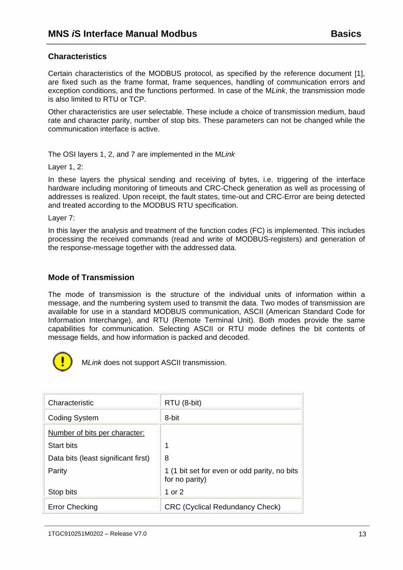
Characteristics
Certain characteristics of the MODBUS protocol, as specified by the reference document [1], are fixed such as the frame format, frame sequences, handling of communication errors and exception conditions, and the functions performed. In case of the MLink, the transmission mode is also limited to RTU or TCP.
Other characteristics are user selectable. These include a choice of transmission medium, baud rate and character parity, number of stop bits. These parameters can not be changed while the communication interface is active.
The OSI layers 1, 2, and 7 are implemented in the MLink
Layer 1, 2:
In these layers the physical sending and receiving of bytes, i.e. triggering of the interface hardware including monitoring of timeouts and CRC-Check generation as well as processing of addresses is realized. Upon receipt, the fault states, time-out and CRC-Error are being detected and treated according to the MODBUS RTU specification.
Layer 7:
In this layer the analysis and treatment of the function codes (FC) is implemented. This includes processing the received commands (read and write of MODBUS-registers) and generation of the response-message together with the addressed data.
Mode of Transmission
The mode of transmission is the structure of the individual units of information within a message, and the numbering system used to transmit the data. Two modes of transmission are available for use in a standard MODBUS communication, ASCII (American Standard Code for Information Interchange), and RTU (Remote Terminal Unit). Both modes provide the same capabilities for communication. Selecting ASCII or RTU mode defines the bit contents of message fields, and how information is packed and decoded.
MLink does not support ASCII transmission.
Characteristic RTU (8-bit)
Coding System 8-bit
Number of bits per character:
Start bits
Data bits (least significant first)
Parity
Stop bits
1
8
1 (1 bit set for even or odd parity, no bits for no parity)
1 or 2
Error Checking CRC (Cyclical Redundancy Check)

Basics MNS iS Interface Manual Modbus
14 1TGC910251M0202 – Release V7.0
Error Detection
There are two types of errors, which may occur in a communication system:
- Transmission error and
- Programming or Communication error
The MLink deals with either type of error as specified in MODBUS specification [1].
The most frequent cause of communication error is noise, unwanted electrical signals in a communication channel. These signals occur because of electrical interference from machinery, damage to the communication channel, impulse noise (spikes), etc. Character framing, a parity check, and a redundancy check detect these errors. When the error occurs, the message is unreliable and the processing of the last received erroneous message stops.
Programming or operational errors are those involving illegal data in a message or difficulty in communicating with a slave. These errors result in an exception response either from Master or Slave station.

MNS iS Interface Manual Modbus Interfaces
1TGC910251M0202 – Release V7.0 15
Interfaces
MLink Connections
MLink provides the facility to connect MNS iS on a single entry point to a Process Control System via MODBUS protocol. Depending on the PCS or PLC application MLink can support either MODBUS RTU or MODBUS TCP. MLink acts always as a standard MODBUS Slave device.
For details see corresponding MNS iS Interface Manual MLink, see section References hereunder.
MLink Redundancy
The MLink is available for both single and redundant configurations. The MODBUS communication protocol is the same in both configurations.
In a redundant configuration two MLinks are used. They are connected together via port Serial 1 for internal data exchange / synchronization. One MLink is configured as ‘Primary’ MLink and the second MLink is configured as ‘Backup’ MLink. In case of a system disturbance where communication is lost to the ‘Primary’, the MLinks will automatically initiate a transfer from Primary to Backup.
Refer to the manual MNS iS Interface Manuals Redundancy, see section References hereunder.
References
Hardware ID numbers 1TGE1020x9Rxxxx 1TGE120021R0010
MLink Types
Hardware available for MNS iS Versions
up to V6.0 from V6.1 onwards
MNS iS Interface Manual MLink
1TGC 910120 M020x 1TGC 91021x M020x
MNS iS Interface Manual Dual Redundancy
1TGC 910260 M020x
Interfaces MNS iS Interface Manual Modbus
16 1TGC910251M0202 – Release V7.0
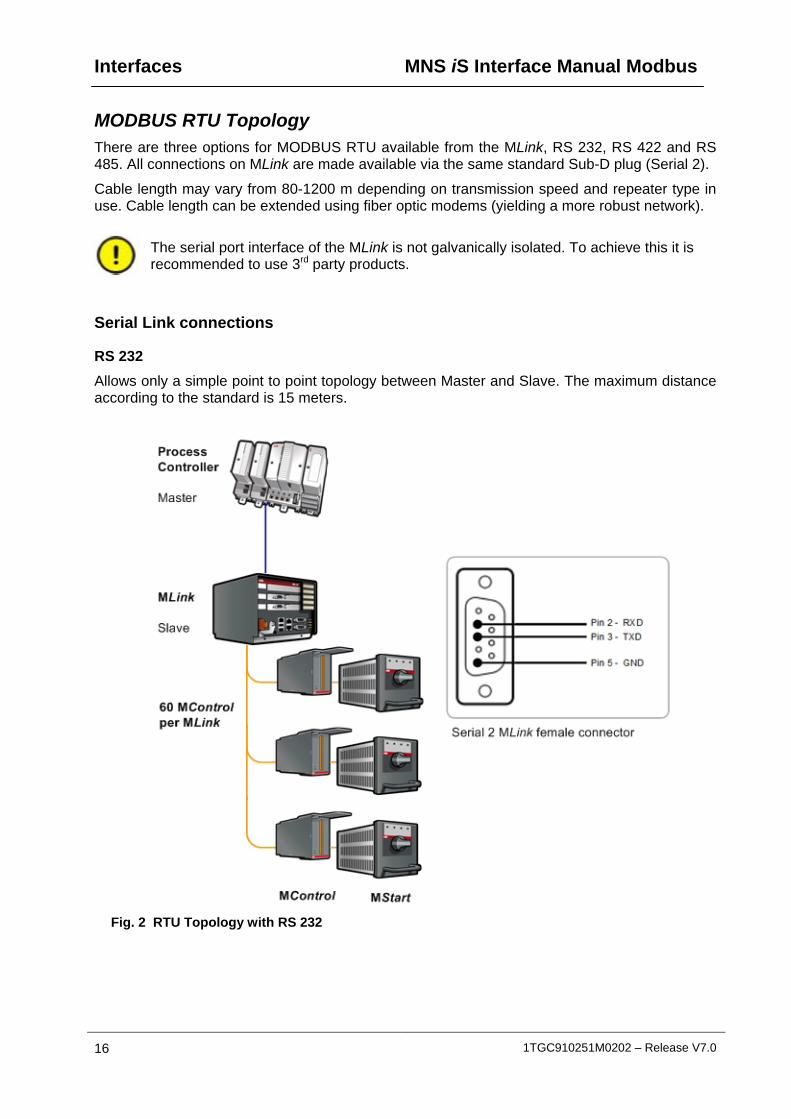
MODBUS RTU Topology There are three options for MODBUS RTU available from the MLink, RS 232, RS 422 and RS 485. All connections on MLink are made available via the same standard Sub-D plug (Serial 2).
Cable length may vary from 80-1200 m depending on transmission speed and repeater type in use. Cable length can be extended using fiber optic modems (yielding a more robust network).
The serial port interface of the MLink is not galvanically isolated. To achieve this it is recommended to use 3rd party products.
Serial Link connections
RS 232
Allows only a simple point to point topology between Master and Slave. The maximum distance according to the standard is 15 meters.
Fig. 2 RTU Topology with RS 232
MNS iS Interface Manual Modbus Interfaces
1TGC910251M0202 – Release V7.0 17
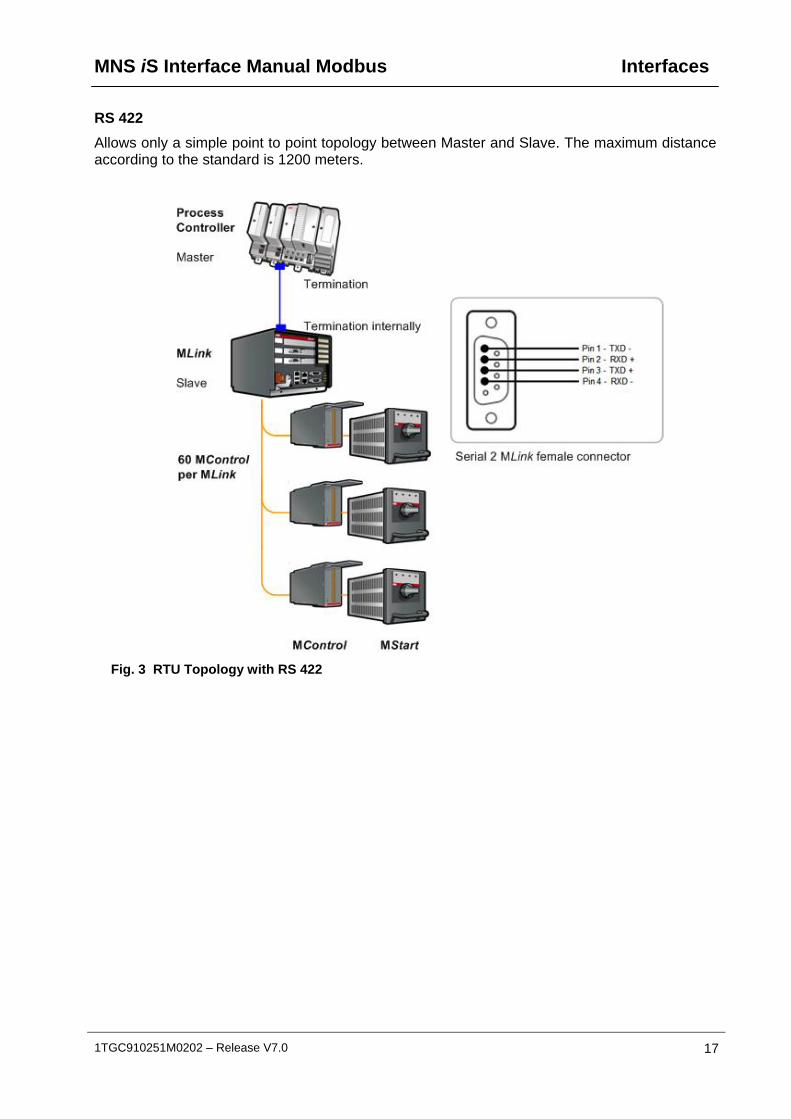
RS 422
Allows only a simple point to point topology between Master and Slave. The maximum distance according to the standard is 1200 meters.
Fig. 3 RTU Topology with RS 422
Interfaces MNS iS Interface Manual Modbus
18 1TGC910251M0202 – Release V7.0
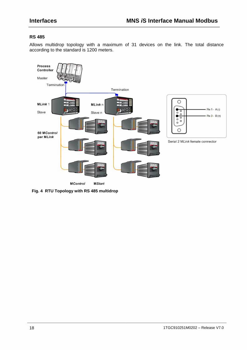
RS 485
Allows multidrop topology with a maximum of 31 devices on the link. The total distance according to the standard is 1200 meters.
Fig. 4 RTU Topology with RS 485 multidrop
MNS iS Interface Manual Modbus Interfaces
1TGC910251M0202 – Release V7.0 19
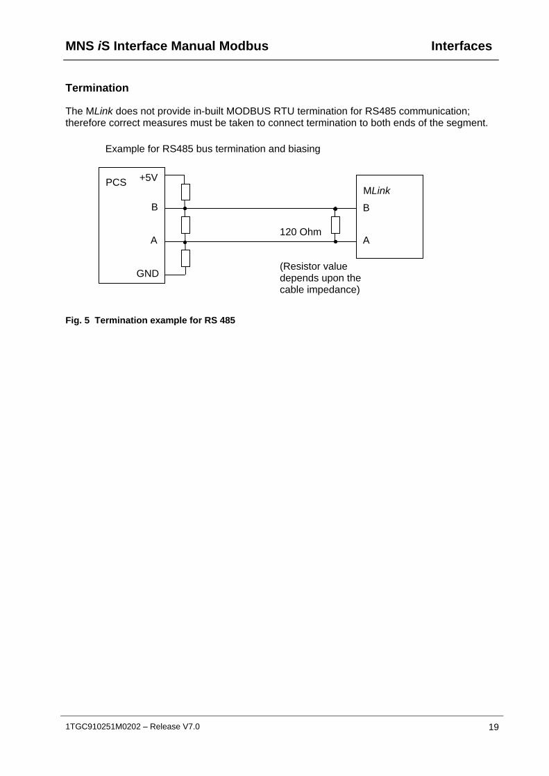
Termination
The MLink does not provide in-built MODBUS RTU termination for RS485 communication; therefore correct measures must be taken to connect termination to both ends of the segment.
Example for RS485 bus termination and biasing
Fig. 5 Termination example for RS 485
MLink PCS
120 Ohm
(Resistor value depends upon the cable impedance)
B
A A
B
+5V
GND

Interfaces MNS iS Interface Manual Modbus
20 1TGC910251M0202 – Release V7.0
MODBUS RTU Communication Settings
Variable Name Default Parameter
Allowed Ranges Remarks
Slave address 247 1 . . . 247 RTU Slave Address
Baud rate 19200 9600, 19200, 38400, 115200
Data Transmission Speed
Parity bit Even None, Even, Odd Used for Error checking
Stop bit 1 1 or 2 Required if no Parity check is used
PLC Time Out enable
No Yes / No Activates PLC time out
PLC Failsafe Time Out
10 1 . . . 100 Delay until Failsafe is activated
Modbus Interface * RS232 RS232, RS485, RS422
Type of serial interface
* only valid for MLink hardware 1TGE120021R0010
Table 1 MODBUS parameter and initial values
Configuration of the parameters is done via MNavigate. The parameters must then be down-loaded to the MLink. After restart of the MLink the settings are taken into effect.
Fig. 6 Parameter Window for MODBUS RTU parameters in MNavigate

MNS iS Interface Manual Modbus Interfaces
1TGC910251M0202 – Release V7.0 21
MODBUS TCP Topology
MODBUS TCP connection is available via the standard RJ45 LAN 1 connector on the MLink. For a direct connection a CAT 5 cross-over cable is to be used. For a network with multiple slaves via a network switch the standard CAT 5 patch cables are used. Maximum cable length for CAT 5 Ethernet cable is 100m.
Fig. 7 TCP topology – direct connection

Interfaces MNS iS Interface Manual Modbus
22 1TGC910251M0202 – Release V7.0
Fig. 8 TCP topology – utilizing network switches
It is recommended that a managed network switch is used to connect MLink to PCS or PLC via Modbus TCP. The switch is not an integral part of the MNS iS assembly but may be delivered together with the switchboard, depending on project scope definition.
MNS iS Interface Manual Modbus Interfaces
1TGC910251M0202 – Release V7.0 23
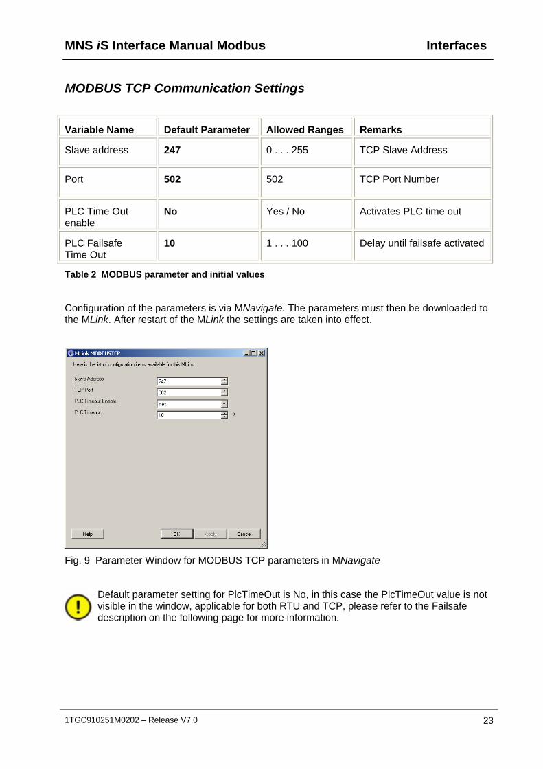
MODBUS TCP Communication Settings
Variable Name Default Parameter Allowed Ranges Remarks
Slave address 247 0 . . . 255 TCP Slave Address
Port 502 502 TCP Port Number
PLC Time Out enable
No Yes / No Activates PLC time out
PLC Failsafe Time Out
10 1 . . . 100 Delay until failsafe activated
Table 2 MODBUS parameter and initial values
Configuration of the parameters is via MNavigate. The parameters must then be downloaded to the MLink. After restart of the MLink the settings are taken into effect.
Fig. 9 Parameter Window for MODBUS TCP parameters in MNavigate
Default parameter setting for PlcTimeOut is No, in this case the PlcTimeOut value is not visible in the window, applicable for both RTU and TCP, please refer to the Failsafe description on the following page for more information.

Interfaces MNS iS Interface Manual Modbus
24 1TGC910251M0202 – Release V7.0
Multiple Master in MODBUS TCP applications
The MLink offers the possibility to support up to 4 MODBUS TCP masters. This function can only be utilized if also the PCS or PLC MODBUS master supports such configuration.
An access control function can be enabled with MNavigate to define the addresses of the MODBUS master devices. In the following configuration example only a PLC or PCS master with IP address 192.168.100.80 is able to access data from MLink.
Fig. 10 Access Control Configuration
Failsafe
In circumstances where a disturbance in the MODBUS communication network needs to be monitored it is possible to select a ‘Failsafe’ state for each MControl. This state has to be defined as a parameter for each MControl separately. The MLink supervises the MODBUS communication to the PCS or PLC if the parameter PLCTimeOut is set to “YES”. The timeout for this connection is set by using the parameter PLCTimeOut (see Table 1 and 2 for initial values).
The MControl must be operating in ‘Remote’ mode for the Failsafe function to be active.
When multiple masters are connected to the MLink (option for MODBUS TCP only) and parameter “Extended Failsafe” is disabled, loss of communication by all masters is required to activate this ‘Failsafe’.
For more information please refer to the ‘Extended Failsafe’ section.
MNS iS Interface Manual Modbus Data Mapping
1TGC910251M0202 – Release V7.0 25
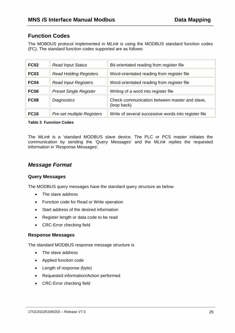
Function Codes The MOBDUS protocol implemented in MLink is using the MODBUS standard function codes (FC). The standard function codes supported are as follows:
FC02 Read Input Status Bit-orientated reading from register file
FC03 Read Holding Registers Word-orientated reading from register file
FC04 Read Input Registers Word-orientated reading from register file
FC06 Preset Single Register Writing of a word into register file
FC08 Diagnostics Check communication between master and slave, (loop back)
FC16 Pre-set multiple Registers Write of several successive words into register file
Table 3 Function Codes
The MLink is a ‘standard MODBUS slave device. The PLC or PCS master initiates the communication by sending the 'Query Messages' and the MLink replies the requested information in 'Response Messages'.
Message Format
Query Messages
The MODBUS query messages have the standard query structure as below.
The slave address
Function code for Read or Write operation
Start address of the desired information
Register length or data code to be read
CRC-Error checking field
Response Messages
The standard MODBUS response message structure is
The slave address
Applied function code
Length of response (byte)
Requested information/Action performed
CRC-Error checking field

Data Mapping MNS iS Interface Manual Modbus
26 1TGC910251M0202 – Release V7.0
Function codes and their relevant address range are shown in the table below.
Function Codes Address / Mapping Area Starting Address used in Modbus Frame
FC02 10001-19999 0-9999
FC04 30001-39999 0-9999
FC03, 06, 16 40001-49999 0-9999
Table 4 Address ranges of function codes
Function Code 02 - Read Input Status
This function allows the control system to obtain the ON/OFF status of discrete inputs from the MLink. With function code 2 following information can be requested.
Life Bits
Status Information
Control Access Information
Alarms
Trips
The valid address range: 10001-19999.
Function Code 03 - Read Output Registers
With function code 03, the control system can read the registers that can store the numerical data, which can be driven to external devices as mentioned below.
Measuring Values
Status as Word-oriented bits
Alarm structure (Warnings/Trips)
The valid address range: 40001-49999
Function Code 04 - Read Input registers
Function code 04 obtains the contents of the input registers. These locations receive their values from devices connected to the I/O structure of field units and can only be referenced, not altered within the system or via MODBUS as mentioned below.
Status as Word-oriented bits
Alarm structure (Warnings/Trips)
The valid address range: 30001-39999
MNS iS Interface Manual Modbus Data Mapping
1TGC910251M0202 – Release V7.0 27
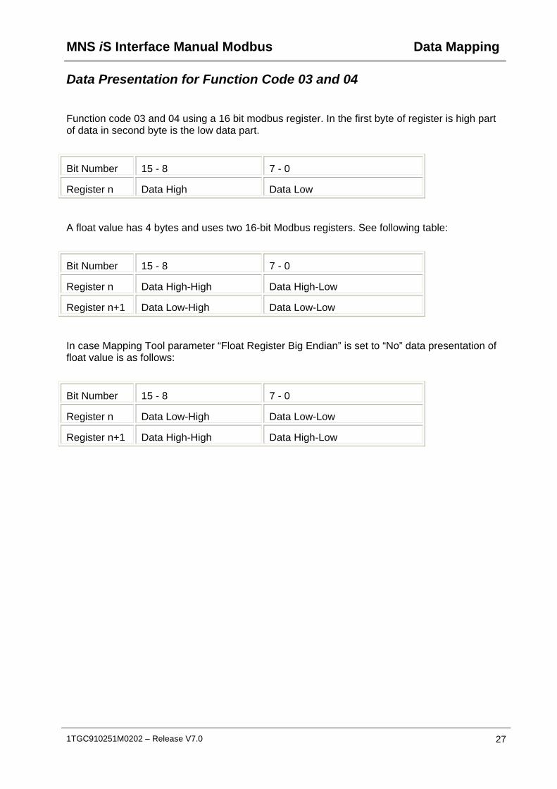
Data Presentation for Function Code 03 and 04
Function code 03 and 04 using a 16 bit modbus register. In the first byte of register is high part of data in second byte is the low data part.
Bit Number 15 - 8 7 - 0
Register n Data High Data Low
A float value has 4 bytes and uses two 16-bit Modbus registers. See following table:
Bit Number 15 - 8 7 - 0
Register n Data High-High Data High-Low
Register n+1 Data Low-High Data Low-Low
In case Mapping Tool parameter “Float Register Big Endian” is set to “No” data presentation of float value is as follows:
Bit Number 15 - 8 7 - 0
Register n Data Low-High Data Low-Low
Register n+1 Data High-High Data High-Low

Data Mapping MNS iS Interface Manual Modbus
28 1TGC910251M0202 – Release V7.0
Function Code 06 - Preset Single Register
Function code 06 allows control system to modify the contents of a single output register. Any output register that exists within the system can have its contents changed by this message i.e.
Switching Commands, other commands
The valid address range: 40001-49999
Outgoing commands utilizing FC06 are always sent, regardless of any change to the command value.
Function Code 08 - Diagnostic Loop Back (Serial Line only) The purpose of the loop back test is to test the communication between Master and Slave station. The data passed in the request data field is returned (looped back) in the response (Sub-function 0000). The entire response message should be identical to the request.
Function Code 16 - Preset Multiple Registers
Function code 16 performs the same function as FC06 but allows modifying the contents of multiple output registers. That means it is possible to send the switching commands to several MControl on a single write command.
The valid address range: 40001-49999
The MLink will only send outgoing commands via FC 16 if there is a change in value compared with the commands previously sent, thus decreasing bus load. If this does not comply with users’ communication philosophy, FC 06 should be used for commands so that each single command will be passed without limitations.
When utilizing FC 16 it is good practice to, once the desired command has been sent and successfully acted upon, then change the command code to NOP. This will ensure that the MControl acts upon a ‘change of state’ from the command control.
MNS iS Interface Manual Modbus Data Mapping
1TGC910251M0202 – Release V7.0 29
Restrictions
General
To ensure optimal performance, a maximum of 60 modbus requests per second is allowed.
According Modbus standard MLink supports up to 16 simultaneous requests. Simultaneous means Modbus master don’t wait until response of MLink, DCS could send more new requests. Please keep in mind: DCS has to count open requests and has to check that never more than 16 requests are open.
Modbus RTU
MLink with Modbus RTU in redundant configuration does not reply to Modbus requests (except FC08) if switchgear bus is not connected properly. Thus the DCS can easily detect a communication problem and use the redundant communication line.
The response time of a modbus slave depends on several parameters, for instance baudrate, number of registers in request and/or reply. Due to this the following procedure for DCS is recommended:
1. DCS sends modbus requests 2. DCS receives modbus reply from slave 3. After receiving of complete modbus reply DCS waits 100ms (or more if from DCS
application required) 4. DCS sends next modbus request
Exception Code Handling
Handling of exception code is supported according to MODBUS specification. The following response telegrams will be sent if a query could not be served:
Exception code 1 (Illegal function)
A Function Code was received that is not supported.
Exception code 2 (Illegal data address)
A register address is out of the valid range.
Exception code 3 (Illegal data value)
The length of the telegram is not valid (start address + register counter > start address range + 1).
Exception code 8 (Memory parity error)
The CRC of the received telegrams is not correct.
Data Mapping MNS iS Interface Manual Modbus
30 1TGC910251M0202 – Release V7.0
Data Mapping Two possibilities exist for data mapping, the default data map as described below and a user defined data map which can be created by the MNS iS Mapping Tool.
The default data map is a selection of data based on typical requirements. If this selection is not accepted in the project, a user data map has to be created.
User Data Map
All available data in a MControl application can be assigned to the corresponding register addresses by using the MNS iS Mapping Tool. This is a proprietary tool for ABB to program the MODBUS registers according to customer requirements.
Default Data Map
Monitoring (Inputs from MControl)
Monitoring of the MControl data handled by the MLink is possible utilizing the following function codes and address ranges.
FC 02 10001 …. 19999 Bit registers
FC 03 40001 …. 49999 Word registers
FC 04 30001 …. 39999 Word registers

MNS iS Interface Manual Modbus Data Mapping
1TGC910251M0202 – Release V7.0 31
Monitoring with Function Code 02
Monitoring of the life and status bits of each MControl via the MLink is detailed in the following tables.
Table 4 Default Modbus Map Life-Bit of MControl
Modbus Function
Code
Modbus-Register
Device Number
Description Remarks
2 10001 1 Life-Bit MControl 1 or MConnect 1 MControl 1 or MConnect 1 is available (comm. ok)
2 10002 2 Life-Bit MControl 2 or MConnect 2 MControl 2 or MConnect 2 is available (comm. ok)
2 10003 3 Life-Bit MControl 3 or MConnect 3 MControl 3 or MConnect 3 is available (comm. ok)
2 10004 4 Life-Bit MControl 4 or MConnect 4 MControl 4 or MConnect 4 is available (comm. ok)
2 10005 5 Life-Bit MControl 5 or MConnect 5 MControl 5 or MConnect 5 is available (comm. ok)
2 10006 6 Life-Bit MControl 6 or MConnect 6 MControl 6 or MConnect 6 is available (comm. ok)
2 10007 7 Life-Bit MControl 7 or MConnect 7 MControl 7 or MConnect 7 is available (comm. ok)
2 10008 8 Life-Bit MControl 8 or MConnect 8 MControl 8 or MConnect 8 is available (comm. ok)
: : : : :
: : : : :
: : : : :
2 10060 60 Life-Bit MControl 60 or MConnect 60 MControl 60 or MConnect 60 is available (comm. ok)

Data Mapping MNS iS Interface Manual Modbus
32 1TGC910251M0202 – Release V7.0
Table 5 Default Modbus Map Bit Status of MControl
Modbus Function
Code
Modbus-Register
Device Number
Description Remarks
2 11001 1 Stopped 1 = Motor Stopped or Tripped or Feeder open
2 11002 1 Runs 1 = Motor Runs or Feeder closed
2 11003 1 CW or K1 1 = Motor Runs Clockwise or K1 energised in Transparent mode
2 11004 1 CCW or K2 1 = Motor Runs Counter Clockwise or K2 energised in Transparent mode
2 11005 1 K3 1 = K3 energised in Transparent mode
2 11006 1 GPI 1 1 = General Purpose Input 1 set
2 11007 1 GPI 2 1 = General Purpose Input 2 set
2 11008 1 Ready 1 = MStart in correct location, & main switch on, & no trip, & no start inhibit.
2 11009 1 Alarm 1 = Any Alarm condition of protection or supervision functions.
2 11010 1 New Trip 1 = Any Trip condition of the protection or supervision functions
2 11011 1 Trip Ack 1 = Current Trip Acknowledged
2 11012 1 Failsafe 1 = Set when MStart runs, after loss off communication.
2 11013 1 Test 1 = MStart with main switch set to test position. (Motor cannot start)
2 11014 1 HW local 1 = Control Access is selected to hardwired I/O from Local / Remote input on MControl.
2 11015 1 Soft local 1 = Control Access is passed from the switchgear control network to the local control station. MControl now responds to the hardwired inputs.
2 11016 1 Bus local 1 = Control Access is passed to any control station on the switchgear control network. Eg. MView.
(continued)

MNS iS Interface Manual Modbus Data Mapping
1TGC910251M0202 – Release V7.0 33
Table 6 Default Modbus Map Bit Status of MControl
Modbus Function
Code
Modbus-Register
Device Number
Description Remarks
2 11017 2 Stopped 1 = Motor Stopped or Tripped or Feeder open
2 11018 2 Runs 1 = Motor Runs or Feeder closed
2 11019 2 CW or K1 1 = Motor Runs Clockwise or K1 energised in Transparent mode
: : : :
2 11945 60 Stopped 1 = Motor Stopped or Tripped or Feeder open
2 11946 60 Runs 1 = Motor Runs or Feeder closed
2 11947 60 CW or K1 1 = Motor Runs Clockwise or K1 energised in Transparent mode
2 11948 60 CCW or K2 1 = Motor Runs Counter Clockwise or K2 energised in Transparent mode
2 11949 60 K3 1 = K3 energised in Transparent mode
2 11950 60 GP IP 1 1 = General Purpose 1 IP set
2 11951 60 GP IP 2 1 = General Purpose 2 IP set
2 11952 60 Ready to start
1 = MStart in correct location, & main switch on, & no trip, & no start inhibit.
2 11953 60 Alarm 1 = Any Alarm condition of protection or supervision functions.
2 11954 60 New Trip 1 = Any Trip condition of the protection or supervision functions
2 11955 60 Trip Ack 1 = Current Trip Acknowledged
2 11956 60 Failsafe 1 = Set when MStart runs, after loss off communication.
2 11957 60 Test 1 = MStart with main switch set to test position. (Motor cannot start)
2 11958 60 HW local 1 = Control Access is selected to hardwired I/O from Local / Remote input on MControl.
2 11959 60 Soft local 1 = Control Access is passed from the switchgear control network to the local control station. MControl now responds to the hardwired inputs.
2 11960 60 Bus local 1 = Control Access is passed to any control station on the switchgear control network. Eg. MView.

Data Mapping MNS iS Interface Manual Modbus
34 1TGC910251M0202 – Release V7.0
Table 7 Default Modbus Map Bit Status of MConnect for Breakers
Modbus Function
Code
Modbus-Register
Device Number
Description Remarks
2 11001 1 Opened 1 = Breaker open
2 11002 1 Closed 1 = Breaker closed
2 11003 1 Tripped 1 = Breaker tripped
2 11004 1 Undefined 1 = Breaker undefined
2 11005 1 Discharged 1 = Breaker discharged
2 11006 1 GPI 1 1 = General Purpose Input 1 set
2 11007 1 GPI 2 1 = General Purpose Input 2 set
2 11008 1
2 11009 1 Alarm 1 = Any Alarm condition of protection or supervision functions.
2 11010 1 New Trip 1 = Any Trip condition of the protection or supervision functions
2 11011 1
2 11012 1
2 11013 1 Test 1 = Breaker is in test mode
2 11014 1 HW local 1 = Breaker is in local mode
2 11015 1
2 11016 1 Bus local 1 = Breaker is in remote mode, Control Access is passed to any control station on the switchgear control network. Eg. MView.
2 11017 2 Opened
2 11018 2 Closed
… … … …

MNS iS Interface Manual Modbus Data Mapping
1TGC910251M0202 – Release V7.0 35
Monitoring with Function Code 03 and 04
Monitoring of the measured (analogue) values from the individual MControl is detailed in the following table.
Table 8 Default Modbus Map measured values of MControl
Modbus Function
Code
Modbus-Register
Device Number
Modbus Register Name
Format Remarks
3 40001 1 Phase current L1 %
or
Current %
Unsigned Int, 2Byte
% age L1 Current
% age Current (MFeed-DC)
3 40002 1 Thermal image Unsigned Int, 2 Byte, Scaled value, multiplied by 10
Used thermal capacity (only available if TOL protection function is used)
3 40003 1 Time to trip Unsigned Int, 2Byte Time before MControl will trip the motor (only available if TOL protection function is used)
3 40004 1 Time to reset Unsigned Int, 2Byte Time required before reset allowed (only available if TOL protection function is used)
3 40005 2 Phase current L1 %
Unsigned Int, 2Byte % age L1 Current
3 40006 2 Thermal image Unsigned Int, 2Byte Used thermal capacity
3 40007 2 Time to trip Unsigned Int, 2Byte Time before MControl will trip the motor
3 40008 2 Time to reset Unsigned Int, 2Byte Time required before reset allowed
: : : : : :
3 40237 60 Phase current L1 %
Unsigned Int, 2Byte % age L1 Current
3 40238 60 Thermal image Unsigned Int, 2Byte Used thermal
Data Mapping MNS iS Interface Manual Modbus
36 1TGC910251M0202 – Release V7.0
capacity
3 40239 60 Time to trip Unsigned Int, 2Byte Time before MControl will trip the motor
3 40240 60 Time to reset Unsigned Int, 2Byte Time required before reset allowed
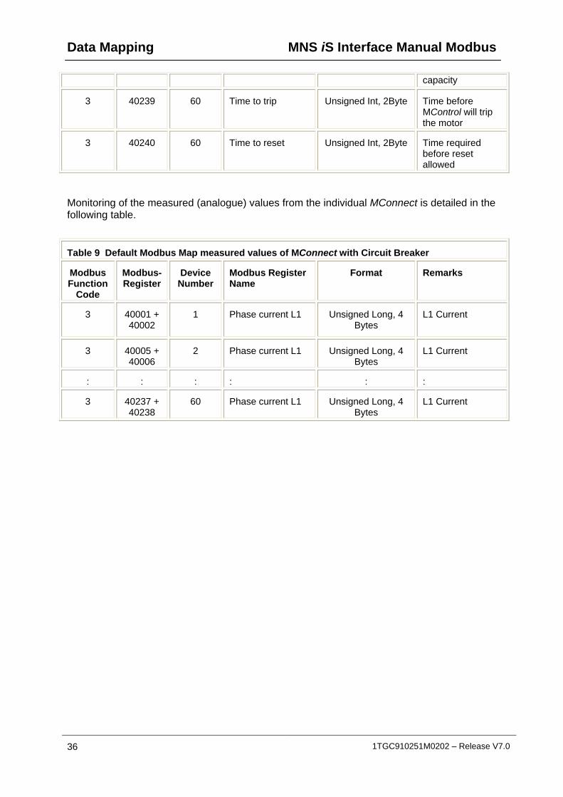
Monitoring of the measured (analogue) values from the individual MConnect is detailed in the following table.
Table 9 Default Modbus Map measured values of MConnect with Circuit Breaker
Modbus Function
Code
Modbus-Register
Device Number
Modbus Register Name
Format Remarks
3 40001 + 40002
1 Phase current L1 Unsigned Long, 4 Bytes
L1 Current
3 40005 + 40006
2 Phase current L1 Unsigned Long, 4 Bytes
L1 Current
: : : : : :
3 40237 + 40238
60 Phase current L1 Unsigned Long, 4 Bytes
L1 Current
MNS iS Interface Manual Modbus Data Mapping
1TGC910251M0202 – Release V7.0 37
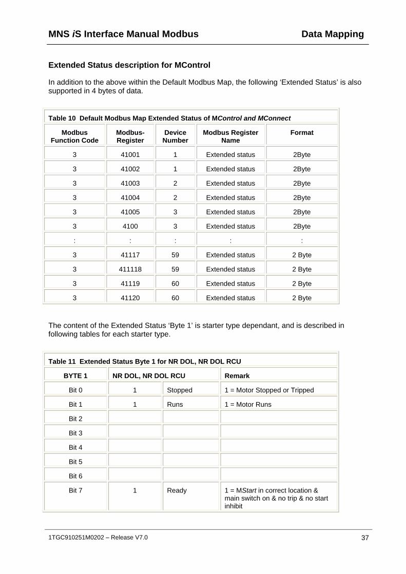
Extended Status description for MControl
In addition to the above within the Default Modbus Map, the following ‘Extended Status’ is also supported in 4 bytes of data.
Table 10 Default Modbus Map Extended Status of MControl and MConnect
Modbus Function Code
Modbus-Register
Device Number
Modbus Register Name
Format
3 41001 1 Extended status 2Byte
3 41002 1 Extended status 2Byte
3 41003 2 Extended status 2Byte
3 41004 2 Extended status 2Byte
3 41005 3 Extended status 2Byte
3 4100 3 Extended status 2Byte
: : : : :
3 41117 59 Extended status 2 Byte
3 411118 59 Extended status 2 Byte
3 41119 60 Extended status 2 Byte
3 41120 60 Extended status 2 Byte
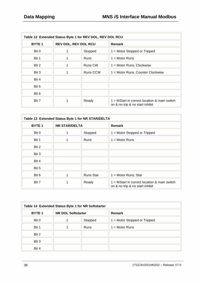
The content of the Extended Status ‘Byte 1’ is starter type dependant, and is described in following tables for each starter type.
Table 11 Extended Status Byte 1 for NR DOL, NR DOL RCU
BYTE 1 NR DOL, NR DOL RCU Remark
Bit 0 1 Stopped 1 = Motor Stopped or Tripped
Bit 1 1 Runs 1 = Motor Runs
Bit 2
Bit 3
Bit 4
Bit 5
Bit 6
Bit 7 1 Ready 1 = MStart in correct location & main switch on & no trip & no start inhibit
Data Mapping MNS iS Interface Manual Modbus
38 1TGC910251M0202 – Release V7.0
Table 12 Extended Status Byte 1 for REV DOL, REV DOL RCU
BYTE 1 REV DOL, REV DOL RCU Remark
Bit 0 1 Stopped 1 = Motor Stopped or Tripped
Bit 1 1 Runs 1 = Motor Runs
Bit 2 1 Runs CW 1 = Motor Runs, Clockwise
Bit 3 1 Runs CCW 1 = Motor Runs, Counter Clockwise
Bit 4
Bit 5
Bit 6
Bit 7 1 Ready 1 = MStart in correct location & main switch on & no trip & no start inhibit
Table 13 Extended Status Byte 1 for NR STAR/DELTA
BYTE 1 NR STAR/DELTA Remark
Bit 0 1 Stopped 1 = Motor Stopped or Tripped
Bit 1 1 Runs 1 = Motor Runs
Bit 2
Bit 3
Bit 4
Bit 5
Bit 6 1 Runs Star 1 = Motor Runs; Star
Bit 7 1 Ready 1 = MStart in correct location & main switch on & no trip & no start inhibit
Table 14 Extended Status Byte 1 for NR Softstarter
BYTE 1 NR DOL Softstarter Remark
Bit 0 1 Stopped 1 = Motor Stopped or Tripped
Bit 1 1 Runs 1 = Motor Runs
Bit 2
Bit 3
Bit 4
MNS iS Interface Manual Modbus Data Mapping
1TGC910251M0202 – Release V7.0 39
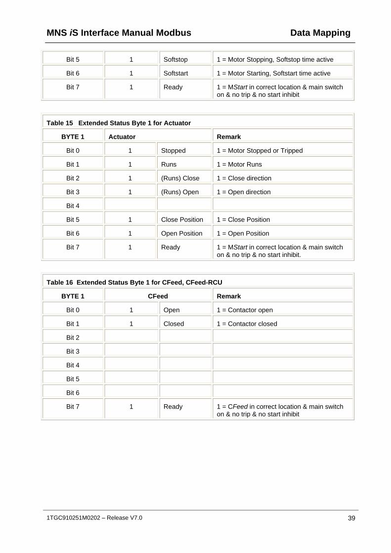
Bit 5 1 Softstop 1 = Motor Stopping, Softstop time active
Bit 6 1 Softstart 1 = Motor Starting, Softstart time active
Bit 7 1 Ready 1 = MStart in correct location & main switch on & no trip & no start inhibit
Table 15 Extended Status Byte 1 for Actuator
BYTE 1 Actuator Remark
Bit 0 1 Stopped 1 = Motor Stopped or Tripped
Bit 1 1 Runs 1 = Motor Runs
Bit 2 1 (Runs) Close 1 = Close direction
Bit 3 1 (Runs) Open 1 = Open direction
Bit 4
Bit 5 1 Close Position 1 = Close Position
Bit 6 1 Open Position 1 = Open Position
Bit 7 1 Ready 1 = MStart in correct location & main switch on & no trip & no start inhibit.
Table 16 Extended Status Byte 1 for CFeed, CFeed-RCU
BYTE 1 CFeed Remark
Bit 0 1 Open 1 = Contactor open
Bit 1 1 Closed 1 = Contactor closed
Bit 2
Bit 3
Bit 4
Bit 5
Bit 6
Bit 7 1 Ready 1 = CFeed in correct location & main switch on & no trip & no start inhibit

Data Mapping MNS iS Interface Manual Modbus
40 1TGC910251M0202 – Release V7.0
Table 17 Extended Status Byte 1 for MFeed / MFeed-DC
BYTE 1 MFeed Remark
Bit 0 1 Open 1 = Isolator open
Bit 1 1 Closed 1 = Isolator closed
Bit 2
Bit 3
Bit 4
Bit 5
Bit 6
Bit 7
Table 18 Extended Status Byte 1 for MConnect with Breaker
BYTE 1 Actuator Remark
Bit 0 1 CB Open 1 = Breaker opened
Bit 1 1 CB Closed 1 = Breaker Closed
Bit 2 1 CB Tr+ipped 1 = Breaker Tripped
Bit 3 1 Undefined 1 = Breaker undefined
Bit 4 1 Discharged 1 = Breaker discharged
Bit 5
Bit 6
Bit 7
MNS iS Interface Manual Modbus Data Mapping
1TGC910251M0202 – Release V7.0 41
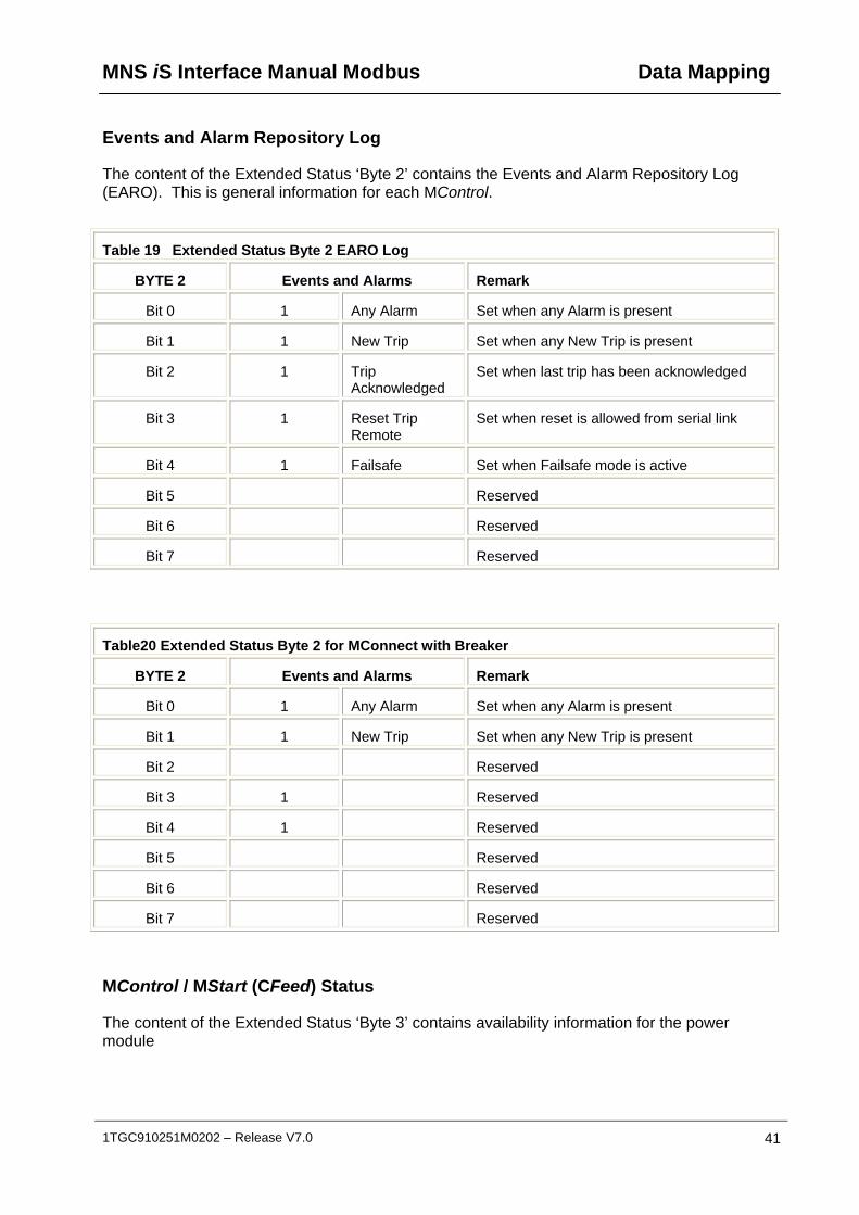
Events and Alarm Repository Log
The content of the Extended Status ‘Byte 2’ contains the Events and Alarm Repository Log (EARO). This is general information for each MControl.
Table 19 Extended Status Byte 2 EARO Log
BYTE 2 Events and Alarms Remark
Bit 0 1 Any Alarm Set when any Alarm is present
Bit 1 1 New Trip Set when any New Trip is present
Bit 2 1 Trip Acknowledged
Set when last trip has been acknowledged
Bit 3 1 Reset Trip Remote
Set when reset is allowed from serial link
Bit 4 1 Failsafe Set when Failsafe mode is active
Bit 5 Reserved
Bit 6 Reserved
Bit 7 Reserved
Table20 Extended Status Byte 2 for MConnect with Breaker
BYTE 2 Events and Alarms Remark
Bit 0 1 Any Alarm Set when any Alarm is present
Bit 1 1 New Trip Set when any New Trip is present
Bit 2 Reserved
Bit 3 1 Reserved
Bit 4 1 Reserved
Bit 5 Reserved
Bit 6 Reserved
Bit 7 Reserved
MControl / MStart (CFeed) Status
The content of the Extended Status ‘Byte 3’ contains availability information for the power module

Data Mapping MNS iS Interface Manual Modbus
42 1TGC910251M0202 – Release V7.0
Table 21 Extended Status Byte 3 MControl / MStart
BYTE 3 Events and Alarms Remark
Bit 0 1 Test Input Isolator set to ‘Test’ position
Bit 1 1 Main Switch Input
Isolator set to ‘On’ position
Bit 2 Reserved
Bit 3 Reserved
Bit 4 Reserved
Bit 5 1 MControl Inhibited
TOL Inhibit / Start Inhibit protection active
Bit 6 1 TOL Inhibit TOL Inhibit protection active
Bit 7 1 TOL Bypass TOL Bypass Active.
Table 22 Extended Status Byte 3 MConnect for Breakers
BYTE 3 Events and Alarms Remark
Bit 0 1 Test Input Breaker set to ‘Test’ mode
Bit 1 Reserved
Bit 2 Reserved
Bit 3 1 Communication running
Modbus communication between MConnect and breaker is running
Bit 4 1 Isolated Breaker is isolated
Bit 5 Reserved
Bit 6 Reserved
Bit 7 Reserved
MNS iS Interface Manual Modbus Data Mapping
1TGC910251M0202 – Release V7.0 43
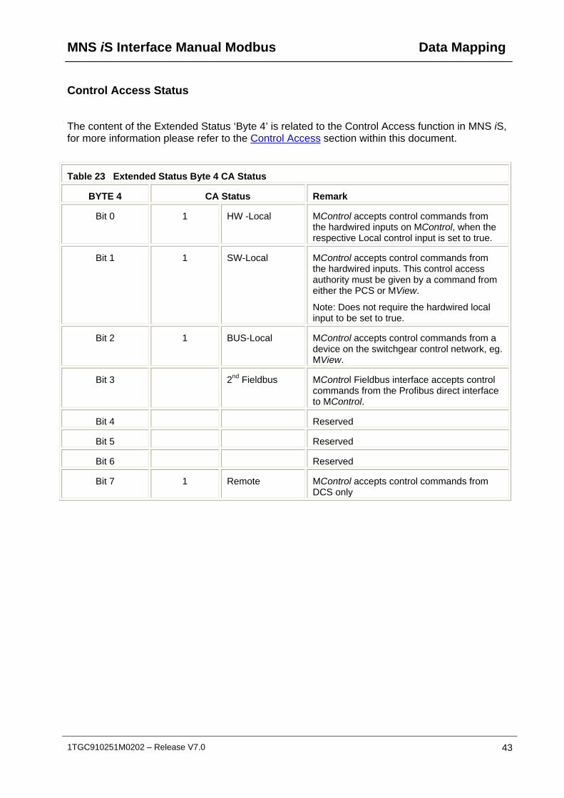
Control Access Status
The content of the Extended Status ‘Byte 4’ is related to the Control Access function in MNS iS, for more information please refer to the Control Access section within this document.
Table 23 Extended Status Byte 4 CA Status
BYTE 4 CA Status Remark
Bit 0 1 HW -Local MControl accepts control commands from the hardwired inputs on MControl, when the respective Local control input is set to true.
Bit 1 1 SW-Local MControl accepts control commands from the hardwired inputs. This control access authority must be given by a command from either the PCS or MView.
Note: Does not require the hardwired local input to be set to true.
Bit 2 1 BUS-Local MControl accepts control commands from a device on the switchgear control network, eg. MView.
Bit 3 2nd Fieldbus MControl Fieldbus interface accepts control commands from the Profibus direct interface to MControl.
Bit 4 Reserved
Bit 5 Reserved
Bit 6 Reserved
Bit 7 1 Remote MControl accepts control commands from DCS only

Data Mapping MNS iS Interface Manual Modbus
44 1TGC910251M0202 – Release V7.0
Table 24 Extended Status Byte 4 CA Status with MConnect for Breakers
BYTE 4 CA Status Remark
Bit 0 1 HW -Local Breaker could only controlled by its push buttons and wired inputs
Bit 1 Reserved
Bit 2 1 BUS-Local Breaker accepts control commands from a device on the switchgear control network, eg. MView.
Bit 3 Reserved
Bit 4 Reserved
Bit 5 Reserved
Bit 6 Reserved
Bit 7 1 Remote Breaker accepts control commands via MConnect from DCS only

MNS iS Interface Manual Modbus Data Mapping
1TGC910251M0202 – Release V7.0 45
Control Commands
Outputs to MControl
Control commands written to the MControl handled by the MLink is possible utilizing the following function codes and address ranges.
FC06, FC 16 40001 …. 49999 Word registers
The following default MODBUS registers must be used for writing control commands to the MControl via the MLink.
Table 25 Default Modbus Command Registers
Modbus Function Code
Modbus-Register
Device Number
Modbus Register Name
Description/Remarks
6/16 43001 1 Command Note: content of the register indicates the command
6/16 43002 2 Command
6/16 43003 3 Command
6/16 : : :
6/16 43060 60 Command
Data Mapping MNS iS Interface Manual Modbus
46 1TGC910251M0202 – Release V7.0
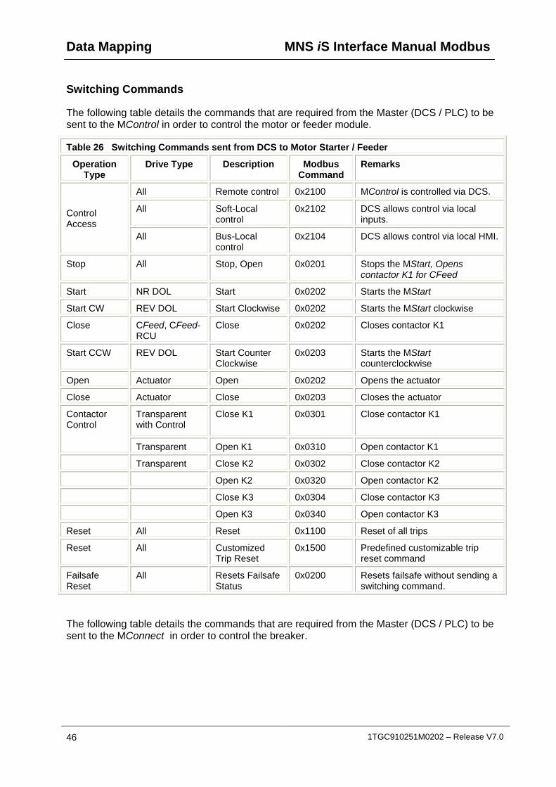
Switching Commands
The following table details the commands that are required from the Master (DCS / PLC) to be sent to the MControl in order to control the motor or feeder module.
Table 26 Switching Commands sent from DCS to Motor Starter / Feeder
Operation Type
Drive Type Description Modbus Command
Remarks
All Remote control 0x2100 MControl is controlled via DCS.
All Soft-Local control
0x2102 DCS allows control via local inputs.
Control Access
All Bus-Local control
0x2104 DCS allows control via local HMI.
Stop All Stop, Open 0x0201 Stops the MStart, Opens contactor K1 for CFeed
Start NR DOL Start 0x0202 Starts the MStart
Start CW REV DOL Start Clockwise 0x0202 Starts the MStart clockwise
Close CFeed, CFeed-RCU
Close 0x0202 Closes contactor K1
Start CCW REV DOL Start Counter Clockwise
0x0203 Starts the MStart counterclockwise
Open Actuator Open 0x0202 Opens the actuator
Close Actuator Close 0x0203 Closes the actuator
Transparent with Control
Close K1 0x0301 Close contactor K1 Contactor Control
Transparent Open K1 0x0310 Open contactor K1
Transparent Close K2 0x0302 Close contactor K2
Open K2 0x0320 Open contactor K2
Close K3 0x0304 Close contactor K3
Open K3 0x0340 Open contactor K3
Reset All Reset 0x1100 Reset of all trips
Reset All Customized Trip Reset
0x1500 Predefined customizable trip reset command
Failsafe Reset
All Resets Failsafe Status
0x0200 Resets failsafe without sending a switching command.
The following table details the commands that are required from the Master (DCS / PLC) to be sent to the MConnect in order to control the breaker.
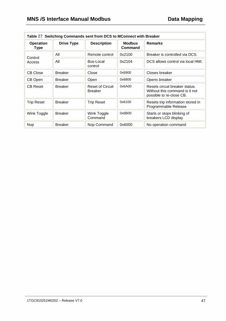
MNS iS Interface Manual Modbus Data Mapping
1TGC910251M0202 – Release V7.0 47
Table 27 Switching Commands sent from DCS to MConnect with Breaker
Operation Type
Drive Type Description Modbus Command
Remarks
All Remote control 0x2100 Breaker is controlled via DCS. Control Access All Bus-Local
control 0x2104 DCS allows control via local HMI.
CB Close Breaker Close 0x6900 Closes breaker
CB Open Breaker Open 0x6800 Opens breaker
CB Reset Breaker Reset of Circuit Breaker
0x6A00 Resets circuit breaker status. Without this command is it not possible to re-close CB.
Trip Reset Breaker Trip Reset 0x6100 Resets trip information stored in Programmable Release
Wink Toggle Breaker Wink Toggle Command
0x6B00 Starts or stops blinking of breakers LCD display
Nop Breaker Nop Command 0x6000 No operation command

Data Mapping MNS iS Interface Manual Modbus
48 1TGC910251M0202 – Release V7.0
General Purpose Outputs Commands
It is possible with the MControl to utilize General Purpose Outputs for various function in connection with logic blocks and or control functions. The General Purpose Outputs are configured with MNavigate with respect to individual MControls. Please refer to the MNavigate Help file for more information.
Two types of output registers are supported;
Persistent The status of these registers are maintained during the Re-Boot of the MControl.
Non – Persistent The status of these registers are not maintained the Re-Boot of the MControl.
For setting of digital signals there a 8 persistent and 8 non persistent registers per MControl. For analogue there is 1 persistent and 1 non persistant.
Table 28 Setting and Resetting of Persistent General Purpose Outputs
Operation Type Drive Type Description Modbus Command Remarks
Set All Set GPO1 0x0601 Sets GP01 to ‘ON’
Set GPO2 0x0602 Sets GP02 to ‘ON’
Set GPO 3 0x0604 Sets GP03 to ‘ON’
Set GPO 4 0x0608 Sets GP04 to ‘ON’
Set GPO 5 0x0610 Sets GP05 to ‘ON’
Set GPO 6 0x0620 Sets GP06 to ‘ON’
Set GPO 7 0x0640 Sets GP07 to ‘ON’
Set GPO 8 0x0680 Sets GP08 to ‘ON’
Reset Reset GPO 1 0x1601 Resets GP01 to ‘OFF’
Reset GPO 2 0x1602 Resets GP02 to ‘OFF’
Reset GPO 3 0x1604 Resets GP03 to ‘OFF’
Reset GPO 4 0x1608 Resets GP04 to ‘OFF’
Reset GPO 5 0x1610 Resets GP05 to ‘OFF’
Reset GPO 6 0x1620 Resets GP06 to ‘OFF’
Reset GPO 7 0x1640 Resets GP07 to ‘OFF’
Reset GPO 8 0x1780 Resets GP08 to ‘OFF’
MNS iS Interface Manual Modbus Data Mapping
1TGC910251M0202 – Release V7.0 49
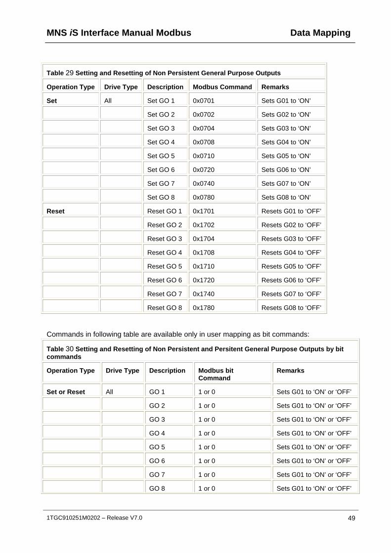
Table 29 Setting and Resetting of Non Persistent General Purpose Outputs
Operation Type Drive Type Description Modbus Command Remarks
Set All Set GO 1 0x0701 Sets G01 to ‘ON’
Set GO 2 0x0702 Sets G02 to ‘ON’
Set GO 3 0x0704 Sets G03 to ‘ON’
Set GO 4 0x0708 Sets G04 to ‘ON’
Set GO 5 0x0710 Sets G05 to ‘ON’
Set GO 6 0x0720 Sets G06 to ‘ON’
Set GO 7 0x0740 Sets G07 to ‘ON’
Set GO 8 0x0780 Sets G08 to ‘ON’
Reset Reset GO 1 0x1701 Resets G01 to ‘OFF’
Reset GO 2 0x1702 Resets G02 to ‘OFF’
Reset GO 3 0x1704 Resets G03 to ‘OFF’
Reset GO 4 0x1708 Resets G04 to ‘OFF’
Reset GO 5 0x1710 Resets G05 to ‘OFF’
Reset GO 6 0x1720 Resets G06 to ‘OFF’
Reset GO 7 0x1740 Resets G07 to ‘OFF’
Reset GO 8 0x1780 Resets G08 to ‘OFF’
Commands in following table are available only in user mapping as bit commands:
Table 30 Setting and Resetting of Non Persistent and Persitent General Purpose Outputs by bit commands
Operation Type Drive Type Description Modbus bit Command
Remarks
Set or Reset All GO 1 1 or 0 Sets G01 to ‘ON’ or ‘OFF’
GO 2 1 or 0 Sets G01 to ‘ON’ or ‘OFF’
GO 3 1 or 0 Sets G01 to ‘ON’ or ‘OFF’
GO 4 1 or 0 Sets G01 to ‘ON’ or ‘OFF’
GO 5 1 or 0 Sets G01 to ‘ON’ or ‘OFF’
GO 6 1 or 0 Sets G01 to ‘ON’ or ‘OFF’
GO 7 1 or 0 Sets G01 to ‘ON’ or ‘OFF’
GO 8 1 or 0 Sets G01 to ‘ON’ or ‘OFF’
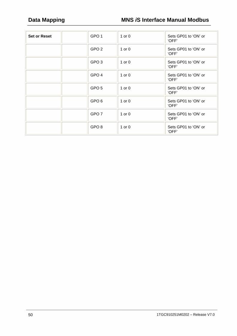
Data Mapping MNS iS Interface Manual Modbus
50 1TGC910251M0202 – Release V7.0
Set or Reset GPO 1 1 or 0 Sets GP01 to ‘ON’ or ‘OFF’
GPO 2 1 or 0 Sets GP01 to ‘ON’ or ‘OFF’
GPO 3 1 or 0 Sets GP01 to ‘ON’ or ‘OFF’
GPO 4 1 or 0 Sets GP01 to ‘ON’ or ‘OFF’
GPO 5 1 or 0 Sets GP01 to ‘ON’ or ‘OFF’
GPO 6 1 or 0 Sets GP01 to ‘ON’ or ‘OFF’
GPO 7 1 or 0 Sets GP01 to ‘ON’ or ‘OFF’
GPO 8 1 or 0 Sets GP01 to ‘ON’ or ‘OFF’
MNS iS Interface Manual Modbus Data Mapping
1TGC910251M0202 – Release V7.0 51
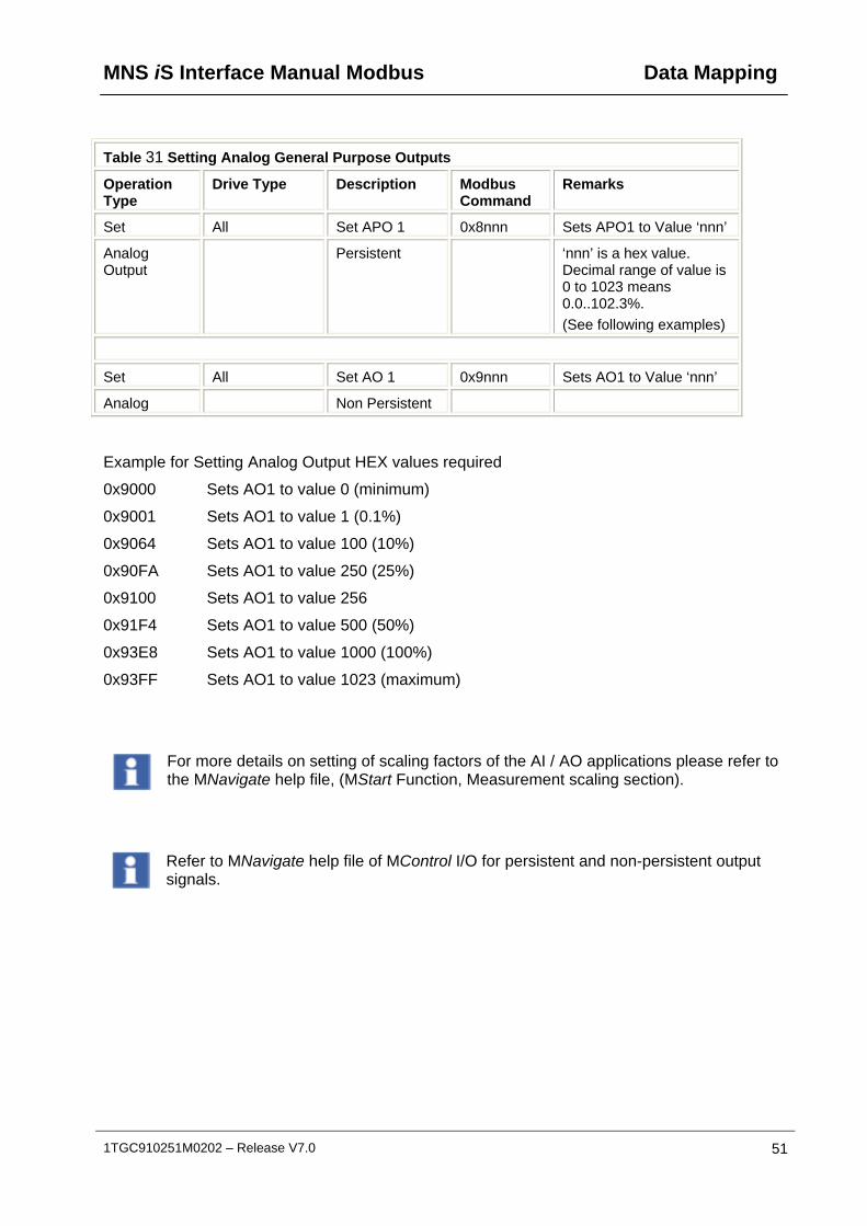
Table 31 Setting Analog General Purpose Outputs
Operation Type
Drive Type Description Modbus Command
Remarks
Set All Set APO 1 0x8nnn Sets APO1 to Value ‘nnn’
Analog Output
Persistent ‘nnn’ is a hex value. Decimal range of value is 0 to 1023 means 0.0..102.3%.
(See following examples)
Set All Set AO 1 0x9nnn Sets AO1 to Value ‘nnn’
Analog Non Persistent
Example for Setting Analog Output HEX values required
0x9000 Sets AO1 to value 0 (minimum)
0x9001 Sets AO1 to value 1 (0.1%)
0x9064 Sets AO1 to value 100 (10%)
0x90FA Sets AO1 to value 250 (25%)
0x9100 Sets AO1 to value 256
0x91F4 Sets AO1 to value 500 (50%)
0x93E8 Sets AO1 to value 1000 (100%)
0x93FF Sets AO1 to value 1023 (maximum)
For more details on setting of scaling factors of the AI / AO applications please refer to the MNavigate help file, (MStart Function, Measurement scaling section).
Refer to MNavigate help file of MControl I/O for persistent and non-persistent output signals.

Data Mapping MNS iS Interface Manual Modbus
52 1TGC910251M0202 – Release V7.0
Switching Commands– Bit Control
The bit control command gives the possibility to control a starter by setting of a single bit. (In addition to control a starter by command codes as described in previous chapter.)
16 single command bits are located in one Modbus word register. More than one bit can set at simultaneously. For example it is possible to set a MControl to remote and to start it with one Modbus register write command.
Function Codes
Depending from Modbus function code the commands are handled as described below.
Function 06: Commands (bit =1) are always sent to MControl, regardless of any change to the command bit value.
Function 16: Commands Are sent only when the command bit is toggled, (either 0 to 1 or 1 to 0)
The following tables detail the registers, bit functionalities and show examples of utilizing Modbus bit commands.
To ensure optimal performance, an MControl (via the MLink) can accept a maximum of 6 bit commands per second.
Table 32 Default Modbus Bit Command Registers
Modbus Function Code
Modbus-Register
Device Number
Modbus Register Name
Description/Remarks
6/16 45001 1 Bit Commands Note: content of the register indicates up to 16 commands
6/16 45002 2 Bit Commands
6/16 45003 3 Bit Commands
6/16 : : :
6/16 : : :
6/16 45060 60 Bit Commands

MNS iS Interface Manual Modbus Data Mapping
1TGC910251M0202 – Release V7.0 53
Table 33 Default Bit Map Control commands for MControl
Execution order is from highest (bit 15) to lowest bit (bit 0).
Bit 15
Bit 14
Bit 13
Bit 12
Bit 11
Bit 10
Bit 09
Bit 08
Bit 07
Bit 06
Bit 05
Bit 04
Bit 03
Bit 02
Bit 01
Bit 00
Register 45001
1 1 1 1 1 1 1 1 1 1 1 1 1 1 1 1 Device Number
Bit 15
Bit 14
Bit 13
Bit 12
Bit 11
Bit 10
Bit 09
Bit 08
Bit 07
Bit 06
Bit 05
Bit 04
Bit 03
Bit 02
Bit 01
Bit 00
Register 45002
2 2 2 2 2 2 2 2 2 2 2 2 2 2 2 2 Device Number
: : : : : : : : : : : : : : : :
Bit 15
Bit 14
Bit 13
Bit 12
Bit 11
Bit 10
Bit 09
Bit 08
Bit 07
Bit 06
Bit 05
Bit 04
Bit 03
Bit 02
Bit 01
Bit 00
Register 45060
60 60 60 60 60 60 60 60 60 60 60 60 60 60 60 60 Device Number
Rem
ote
Bus
Lo
cal
Sof
t Lo
cal
Res
et
Sto
p
Sta
rt (
CW
)
Sta
rt C
CW
Clo
se K
1
Ope
n K
1
Not
us
ed
Res
et
GP
O3
Set
G
PO
3
Res
et G
PO
2
Set
GP
O2
Res
et G
PO
1
Set
GP
O1
Bit Function
The content of the register indicates the command
Please Note:
Actuator drive type control and MConnect is not supported with ‘Bit Control’.

Data Mapping MNS iS Interface Manual Modbus
54 1TGC910251M0202 – Release V7.0
Following table shows how to control a starter by control command bits
Execution order is from highest (bit 15) to lowest bit (bit 0).
Table 34 Possible Control Command bit combinations
Execution order is from highest (bit 15) to lowest bit (bit 0).
Bit 15
Bit 14
Bit 13
Bit 12
Bit 11
Bit 10
Bit 09
Bit 08
Bit 07
Bit 06
Bit 05
Bit 04
Bit 03
Bit 02
Bit 01
Bit 00
Control command
Rem
ote
Bus
Lo
cal
Sof
t Lo
cal
Res
et
Sto
p
Sta
rt (
CW
)
Sta
rt C
CW
Clo
se K
1
Ope
n K
1
Not
us
ed
Res
et
GP
O3
Set
G
PO
3
Res
et G
PO
2
Set
GP
O2
Res
et G
PO
1
Set
GP
O1
1 0 0 0 1 0 0 0 0 0 0 0 0 0 0 0 Remote + Stop
1 0 0 0 0 1 0 0 0 0 0 0 0 0 0 0 Remote + CW
1 0 0 0 0 0 1 0 0 0 0 0 0 0 0 0 Remote + CCW
1 0 0 0 0 0 0 1 0 0 0 0 0 0 0 0 Remote + K1 close
1 0 0 1 0 1 0 0 0 0 0 0 0 1 0 1
Remote + trip reset + Start + Set GPO2 + Set GPO1
0 0 1 0 0 0 0 0 0 0 0 0 0 0 0 0 Go to Soft local
1 0 0 0 0 0 0 0 0 0 0 1 0 1 0 1 Set GPO’s 1,2,3

MNS iS Interface Manual Modbus Data Mapping
1TGC910251M0202 – Release V7.0 55
Redundant MLink MODBUS data
The following additional data mapping is provided for a redundant data interface to determine the status of MLink (Primary/Backup, Redundancy Error). It is also possible to send commands to force a change-over.
Please refer to the Redundancy Manual for further details.
Table 35 Redundant data for monitoring by the Modbus master
Modbus Function
Code
Modbus-Register
Device Number
Modbus Register Name
Format Description/Remarks
2 12001 Primary MLink Bit Set to 1 indicates MLink is Primary
2 12002 - Redundancy Error Bit Set to 1 indicates Redundancy error.
Table 36 Redundant Command possible from the Modbus master
Modbus Function Code
Modbus-Register
Device Number
Modbus Register Name
Format Description/Remarks
6/16 44001 - Force to changeover to Backup MLink
Unsigned Integer 2Byte
Master must send 0x0001 to force to changeover
This command may be sent to either the Primary or Backup MLink to initiate a changeover.

Data Mapping MNS iS Interface Manual Modbus
56 1TGC910251M0202 – Release V7.0
Control Access
Control Access (CA) is a mechanism within MNS iS to define and determine which user interface has control rights to operate the MStart or MFeed modules. These interfaces are defined below in command handling. Control Access rights can be given, for example, by a specific command sent to switch operation rights from push-button (hardwired to MControl) to any other interface connected via the MLink (e.g. MView or DCS).
Command Handling
The control access command defines the control rights of defined interfaces for an MControl.
Remote - MControl switches to Remote operation mode and can be operated via Fieldbus from process control system (DCS / PLC)
Bus-Local - MControl switches to the Bus-Local mode and operation is possible: via MView (local operation panel in switchboard) or via web interface (similar to MView).
Soft-Local - MControl switches to local mode, and operation is possible via the digital inputs on the MControl. Soft Local does not require a hardware input to be set. Soft-Local may only be activated by a command sent from the DCS or MView. It may also be configured directly in the MControl parameters.
Hardware-Local - MControl switches to the Hardware-Local mode and operation is possible only through digital inputs on MControl Hardware. Hardware-Local must be activated by the setting the input on the MControl
Table 37 Commands and status for Control Access (default map)
Command Command Command Status Bit
CA Interface Auto Mode
(CA Remote)
Soft Local
(CA SoftLocal)
Bus Local
(CA BusLocal)
Auto Mode
(Bus Control)
DCS only 1 0 0 1
MView (Web interface)
0 0 1 1
Hardware Inputs (Hardware Local or Soft Local)
0 1 0 0
Hardware Local (Hardware Inputs)
X X X 0
The Remote signal may be monitored / mapped by selecting the ‘CA Remote’ Input Signal in the parameterization options in MNavigate, it can then be utilized in conjunction with the ‘General Purpose Inputs’ of the MControl, see Table 6. This is also possible by monitoring the Extended Status, see Table 18.

MNS iS Interface Manual Modbus Data Mapping
1TGC910251M0202 – Release V7.0 57
Notes:
At any time any control station can obtain the control access by sending a control access command to MControl. On MView (or web interface) the user must have the appropriate user right to do so.
Hardware-Local must be activated by the setting the input on the MControl.
CA Remote is set if the command ‘Remote Control’ command is sent to the MControl from the DCS. Only then it is possible to send switching commands from the DCS.
CA SoftLocal (or CA BusLocal) will be active if Auto Mode is not set and the Soft Local (or Bus Local) command bit goes from 0 to 1.
Hardware-Local overrides all other CA Levels. It is not possible for the DCS or MView to take control when the MControl is set to HW-Local.
The current active control station (Control Access Owner) can be identified by reading data through DP-V1 functionality, see Table 25.
Recommended procedure for sending control commands for a motor starter
1. Set the MControl to "Remote" with the command “0x2100”
2. Set the desired state, "Run Reverse", "Off", "Run Forward" or "Trip Reset"
3. Wait until desired state is shown in motor state (received from Slave).
4. Reset previous command "Run Reverse", "Off", "Run Forward" or "Trip Reset"

Data Mapping MNS iS Interface Manual Modbus
58 1TGC910251M0202 – Release V7.0
Extended Failsafe for Modbus TCP
This function allows supervision of the communication path between the DCS and each MControl. If the DCS or DCS communication fails only the related (configured) MControls activate failsafe mode. The MControl executes the parameterized action (e.g. Stop the motor, Start the motor, etc. -> for details ref. to Failsafe description of each motor starter type in the MNavigate Help File).
Following examples explains the general functionality:
DCS 1 controls MControl 1 and 2 connected to MLink 1
DCS 2 controls MControl 3 and 4 connected to MLink 1
DCS 3 monitors only several MControls connected to MLink 1 or 2
DCS 4 controls MControl 60 and MControl 30 of a second MLink 2

MNS iS Interface Manual Modbus Data Mapping
1TGC910251M0202 – Release V7.0 59
Failure examples
The following scenarios shows failure handling in a non redundant system and redundant systems.
Non-Redundant system - One DCS controller fails
DCS 2 is unavailable (e.g. Ethernet cable broken or power loss); only MControl 3 and 4 go to Failsafe mode :
Data Mapping MNS iS Interface Manual Modbus
60 1TGC910251M0202 – Release V7.0
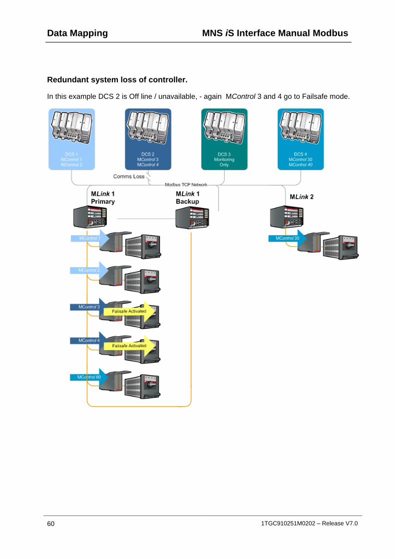
Redundant system loss of controller.
In this example DCS 2 is Off line / unavailable, - again MControl 3 and 4 go to Failsafe mode.

MNS iS Interface Manual Modbus Data Mapping
1TGC910251M0202 – Release V7.0 61
Redundant system loss of communication to MLink.
In this example DCS 2 is available, however communication has been lost to the Primary MLink. As the redundancy handling is executed between Primary and Backup MLinks, no Failsafe is activated. For more information please refer to the Redundancy Interface Manual..
Data Mapping MNS iS Interface Manual Modbus
62 1TGC910251M0202 – Release V7.0
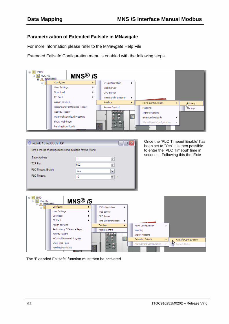
Parametrization of Extended Failsafe in MNavigate
For more information please refer to the MNavigate Help File
Extended Failsafe Configuration menu is enabled with the following steps.
Once the ‘PLC T has been set to ‘Yes to enter the ‘PLC Timeout’ time in seconds. Follow te
imeout Enable’ ’ it is then possible
ing this the ‘Ex
The ‘Extended Failsafe’ function must then be activated.

MNS iS Interface Manual Modbus Data Mapping
1TGC910251M0202 – Release V7.0 63
This then enabl‘Controllers’ (DCSnames for each coan the IP Addresentered.
es the number of / PLC) to be set, ntroller can be given s for each must be
Examples of setting shown.
Notes: The Extended Failsafe settings must be configured individually for each MLink in the project !
The maximum number of configurable controllers is 12.
Note: If number of controller is increased then each new controller has the default address 0.0.0.0 and a default controller name to indicate that the settings must be parameterised!
Whenever a controller is added or deleted this procedure and the following Failsafe Matrix must be updated.

Data Mapping MNS iS Interface Manual Modbus
64 1TGC910251M0202 – Release V7.0
Failsafe Matrix
After the Extended Failsafe Configuration is finished user can start to specify the relation between DCS Controller and the MControl (e.g. motor) in the Failsafe Matrix.
To specify a connection simply the check the respective box.
The first column shows all configured devices connected to the selected MLink.
The following columns show the given DCS Controller names and the related specified IP address (as configured in the Extended Failsafe Configuration window)
In following example Failsafe mode is initiated for "Pump-1" if communication between MLink and DCS Controller 10.49.75.61 fails, irrespective of communication status of the other configured DCS Controllers:
MNS iS Interface Manual Modbus Data Mapping
1TGC910251M0202 – Release V7.0 65
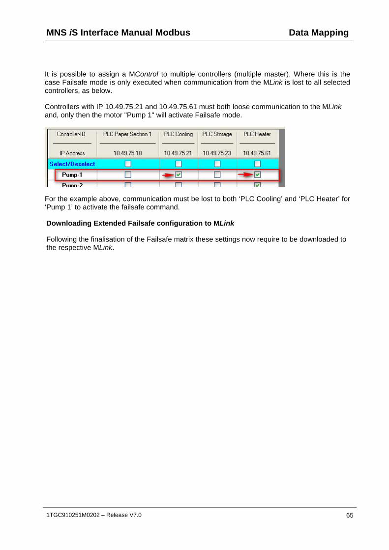
It is possible to assign a MControl to multiple controllers (multiple master). Where this is the case Failsafe mode is only executed when communication from the MLink is lost to all selected controllers, as below.
Controllers with IP 10.49.75.21 and 10.49.75.61 must both loose communication to the MLink and, only then the motor "Pump 1" will activate Failsafe mode.
For the example above, communication must be lost to both ‘PLC Cooling’ and ‘PLC Heater’ for ‘Pump 1’ to activate the failsafe command.
Downloading Extended Failsafe configuration to MLink
Following the finalisation of the Failsafe matrix these settings now require to be downloaded to the respective MLink.

Troubleshooting MNS iS Interface ManualModbus
66 1TGC910251M0202 – Release V7.0
Troubleshooting
LED - Status Information
For further details on LED indication please refer to the MLink Interface Manuals, reference hereunder.
Hardware ID numbers 1TGE1020x9Rxxxx 1TGE120021R0010
MLink Types
Hardware available for MNS iS Versions
up to V6.0 from V6.1 onwards
MNS iS Interface Manual MLink
1TGC 91012x M020x 1TGC 91021x M020x
Comms check
If it is not possible to achieve communications between the Modbus master and the MLink, in the first instance please check the following:
For Modbus RTU Cable connection and Termination are all in line with the requirements detailed in the Serial Link connections section.
Slave address parameters for RTU should in line with the ranges defined in Table 1
Slave address parameters for Modbus TCP should in line with the ranges defined in Table 2. In addition please also check the following:
IP Address settings required
For further clarifications with respect to Modbus TCP network setting, please contact the responsible network administrator for the project.
Note:
The Broadcast address is calculated by MNavigate from a combination of the IP Address and the Subnet mask.


Contact us ABB Low Voltage Systems Copyright© 2012 ABB
All rights reserved. Publication No. 1TGC910251M0202
Publication Editor: ABB Automation Products GmbH Ladenburg, Germany Local Contacts on www.abb.com/mns