mobile 4d imaging technologies for construction & life...
TRANSCRIPT

George M. Williams [email protected]
15985 NW Schendel Ave
Beaverton, OR 97006 WWW.VOXTEL-INC.COM
Mobile 4D Imaging Technologies for Construction & Life-cycle BIM model dimensional information management
Advanced Methods of Manufacturing Workshop September 29, 2015
DOE 2015.2, Topic 32F (DE-SC0013835; Jun 8, 2015 – Mar 7, 2016)

About Voxtel Companies
• Founded 1999
• 50 employees (30% PhD, 80% Advanced Degree)
VoxtelOpto (Beaverton, OR) Eye-safe 3D Imaging Technologies
• Avalanche Photodiode (APD) and PIN Detectors and Arrays • Eye-safe Pulsed Laser Transmitters • Rangefinders, 3D Imaging, LADAR, and Electro-Optic Systems • Readout Integrated Circuits (ROICs) • Active & Act./Passive Focal Plane Array (FPA)
Voxtel Nano (Eugene, Oregon) Nanocrystal Printed Imagers and Threat Reporting Sensors
• Nanotechnology Technologies Group • Nanocrystal VIS-SWIR-Thermal IP Imaging Products • Analytical Facilities (HRTEM, SIMS, XRD, UPS/XPS)
Vadient Optics (Corvallis, Oregon) 3D Freeform GRIN Optics
• Spun out in 2013; Inkjet-printed Solid-Freeform Fabrication of GRIN Optics

3
Vertically-integrated 3D Imaging
Eye-safe Laser Rangefinders
Avalanche Photodiodes & APD Detector Arrays
Readout Integrated Circuits & Monolithic Imagers
Eyesafe Rangefinders
Asynchronous Event-driven Photon Counter
with Time Stamping
SWIR & MWIR Active/Passive Imaging (See Spot / Time Spot)
Low-noise MHz-GHz SWIR Receivers
High-gain, Low-noise APDs
InGaAs Photodiode and APD Arrays
Waveform Sampling (1 ns time slices) Back-illuminated Mesa Arrays
LRF OEM Module
Sparsified, Event-driven Amplitude or Arrival
Time
Eye-safe Lasers
APD Photoreceivers
LADAR FPAs & Receivers
LRF rRceivers
APD Receiver Modules
LADAR Receivers LIDAR FPAs
3D Wafer Stacked Imagers
100 µJ 1 mJ 50 kHz, 10 µJ

4
Mobile LADAR 3D Tool for Civil, Construction, and Building Management
.
Problem • $100M construction job, between $0.5M and $1M
spent on track of tens thousands of things on site • Approximately 2% costs devoted to manually
intensive quality control and inventory management • One of the challenging tracking tasks is the
determination of geometry changes • The tracking of amorphous data is important:
excavation, spoil pipes, concrete placement, etc • Also need to capture as-built conditions and
clarify complex operations • Mechanical, Electrical and Plumbing (MEP) monitoring
is resource intensive • low resolution scanning equipment do not support
sufficient imaging of small details, (e.g., anchor bolts) • Design-construct-BIM integration not established • Automation and robotic need to be established
Solution • A low cost, compact mobile laser 3D imaging system that can
image a construction area in "real-time". • wirelessly transfer range data from the field to a remote office. • Link the rangefinder to GPS position and attitude
measurement systems so that the range data can be registered to a known reference frame.
• Develop a user interface to: (a) automatically operate the scanner. (b) display the 3-D data. (c) determine cut/fill requirements

5
Analog Full-waveform, Sampled, and Photon Counting Time of Flight (tof) LADAR Operating Modes

6
DOE 2015.2, Topic 32F (DE-SC0013835; Jun 8, 2015 – Mar 7, 2016) UV-Based LADAR 3/4D Imaging for Building and Construction Management
LIDAR Scanning principle Vertically rotating mirror w/MEMS scanner Range principle Ultra-high speed time-of-flight Scanning Speed 1 million pts/sec Maximum range 450 m Range noise <1 – 2 mm
Range measurement Laser class 1, eye safe in accordance with IEC EN60825-1 Laser wavelength 1.535 μm, invisible Laser beam diameter. 6–10–34 mm @ 10–30–100m Minimum range 1 km m on reflectivity, 300 m on very low reflectivity (5%) Range noise. . , <(1) 2 mm from 2 m- 120 m on 18–90% reflectivity Range systematic error.. <2 mm
Scanning Field of view.. 30°x 7° Angular accuracy. .80 μrad
Environmental Temperature Operating –20 °C to +50 °C (–4 °F to +122 °F) Storage .–40 °C to +70 °C (–40 °F to +158 °F) Operating humidity . 100% condensing Dust and water protection. . . .IP54 Shock:Non-operating drop test. .Survive 2 m (6.6 ft)
Visible Camera Lens type. . . .f-theta Angle per pixel. 0.39 mrad/Pix (1.33 arcmin/Pix) Focal length 3.63 mm (0.14 in) Depth of field. 0.1 to ∞ m Calibration of Camera. better than 1 Pix

7
ROXTM Miniature Laser Rangefinder w/ 9-axis IMU for Georeferenced Range Vectors & Ballistics Computing
Eye-safe APD LRF Features • Smallest fully integrated COTS micro-
laser rangefinder available • 15 mm optic
• 8x (4 mm) expander for 0.5 mrad divergence
• Temperature-stabilized APD photoreceiver • no thermoelectric cooling required
• Eye-safe pulsed laser • Diffraction-limited beam delivers
photons to target • 10 Hz – 200 KHz @ 100 µJ – 10 uJ
• Simple USB interface with Bluetooth option
• Visible (640 nm) boresight laser • Rechargeable LIPO battery • Multi-pulse (10) accumulation • Waterproof IP65
Eyesafe APD Performance • 0.6 nW NEP / 3 nW Sensitivity • 3 km range performance (15 mm
option) / 8 km (25 mm optic) • < 100 mm range precision • < 0.75 mrad beam divergence (5x beam
expander) • 1 M shot lifetime • 45 gram weight • 1.7 W / 80 mW power • 200K shots per battery charge
9-axis IMU
ROXTM Laser Rangefinder (integrates below)
OEM Module
Avalanche Photodiode Receiver (Rx) Low-noise ASIC Low-noise APD with 10x better sensitivity than PIN detector • Enables 10x lower laser power and
commensurate SWAP-C reduction No thermoelectric cooler → temp-compensated gain Integrated microcontroller provides flexible control and biasing Factory calibration over -45oC to +80oC operation stored in each receiver
Micro-miniature Passive Q-switch Er-doped Transmitter (Tx)
100 – 300 µJ pulse energy achieves 10 km ranging 10 Hz to 20 kHz pulse rates for multi-pulse and stabilized pointing Excellent beam quality (M2 = 1.1) extends range operation Enhanced reliability over mJ-class lasers Highly reliable passive Q-switch, self-aligned design is low cost
Laser Rangefinder (LRF) OEM Module Integrated laser driver, temperature compensation, multi-pulse accumulation, and range-walk (time-over-threshold, TOT) calibration Serial I/O Onboard storage of operating modes On-board 12-bit digitizer Designed for integration with rifle scopes and portable electronics
Integrated Commercial LRFs Up to 7 km range operation with 25 mm (and smaller) optics Less than 100 mm resolution with range walk (TOT) Multi-pulse processing for extended range with small apertures
APD Receiver Er:glass Laser

8
Laser Safety
Maximum permissible exposure (MPE) as power density versus
exposure time for various wavelengths
MPE as energy density versus wavelength for
various exposure times (pulse durations).
• Class 1 laser maximum permissible exposure (MPE) per pulse (10 ns) is ~6,000 greater for 1550 nm:
• 905 nm: 1.37*1011 photons/mm2
• 1550 nm: 7.8*1014 photons/mm2 • allowing eyesafe lasers to be used with:
• smaller sized collimating and collection optic • arrays • full waveform returns
• Range is roughly proportional to R2 so 1550 nm eyesafe operation can • range 77x times further, and • scatters less in aerosols and rain
MPE as energy density versus exposure time for various wavelengths.

9
ROX Tx: Ultra-miniature Er-doped Solid-state Laser
Eye-safe Class 1 (1535 nm)
Laser pulse energy 10 – 200 μJ
Short pulses 3.8 ns FWHM
Low beam divergence 4 mrad (0.25 mrad with 12x expander)
Beam quality 1.06 x DL
Pulse averaging 1 – 50 KHz
Manufacturable, low-cost solid-state
Domestic component sources
Measured M2 = 1.06*DL Data
10-200 µJ (1 mJ) Er:Ceramic Laser
Replaces expensive, large size, weight, power, and lower peak power fiber lasers (3 uJ, < 6 kW pp) – &
– 100 nJ laser diodes Ultra-compact, high rate micro-chip laser

10
ROXTM LRF Range Performance

11
UAV/UGV 3D Imaging LADAR System
• Ultra-miniature custom-designed, dual-wavelength (1550 nm) diode-pumped solid-state microchip laser
• Compact afocal achromatic optical system • achromatic holographic optical element (HOE)
scanner • High-gain, low-excess-noise APD array for each
channel • 1.6 GHz full-waveform digitization with leading
edge time-to-digital (TDC) conversion • Real-time waveform processing using a Xilinx
Zynq-based processing system • Real-time geo-registration and uncertainly
modeling using GPS/INU data with 9-axis IMI • Boresighted stereo cameras with depth
processing • Over 1 TB of local solid-state memory • RF communications link • Robust, modular design,

12
Fusion of Multiple Sensor Modalities
• Optimal photointerpretation (image data is continuous) • Use of RGB, CIR images with 8+ bit per channel • Already experienced operators, well known
procedures and system • New digital cameras have bad B/H ratio so Z quality is poor
(respect to the LiDAR data at the same flight height) • Data quality is not geometrically constant (Z in particular)
because depends on the operator (stereoscopic perception)
• Image correlation often have problems exactly where we need (for ex. roof edges)
Photogrammetry (3D imagery) alone is not enough…
LiDAR alone is not enough…
• Optimal precision (especially Z) respect to the photogrammetry at the same flight height
• Possibility to classify the points cloud • Data quality is geometrically constant (Z in
particular) because does not depend on the operator (snap)
• Data have low costs and short acquisition times • Interpretation is very poor because the data is
discrete • Point density impacts a lot on cost • The points don’t have directly the color of the
objects • XY precision is poorer than Z

13
Sensor Fusion
• Stereo imagery are used for XY and photointerpretation
• LiDAR point clouds are used for updating collimation mark height (Z)
• use camera image sequences (video) to quickly navigate…
• Use the point cloud for the 3D precise measure task
• Use the images to recognize objects
Combine stereo images and LiDAR point clouds to obtain the best accuracy and efficiency
14
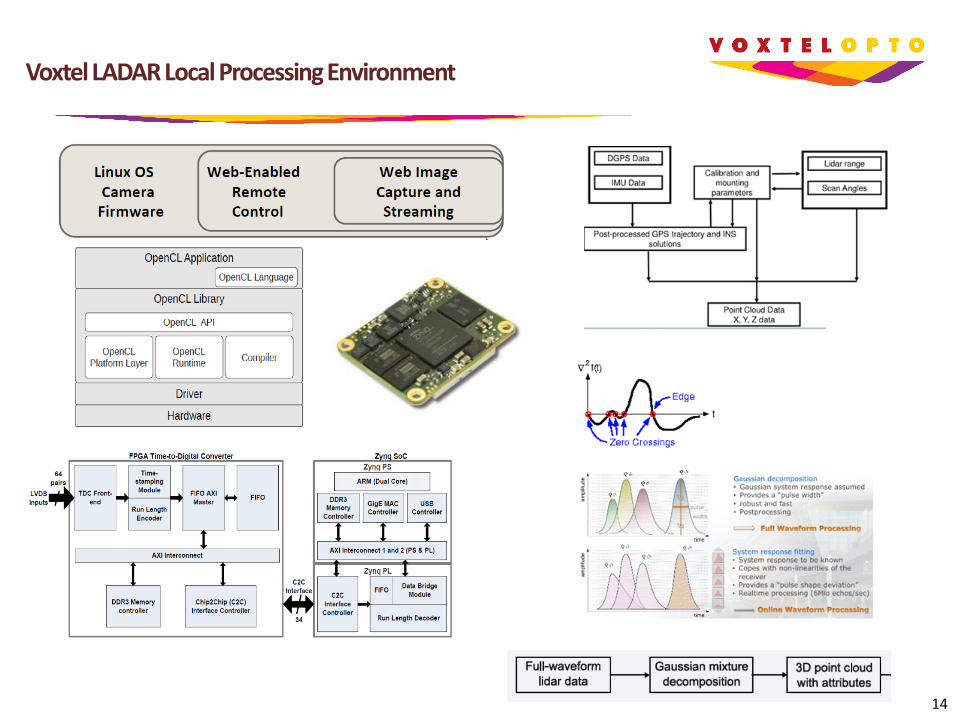
Voxtel LADAR Local Processing Environment

15
2D Full-waveform Sampling 3D LIDAR
Parameter Specification
Pixel pitch (µm) 50
Resolution (X by Y pixels) 128 x 128
Windowing resolution (pixels) 16 x 16
Return samples (per pixel) 24 (circular)
Program sample time (ns) 2 – 16 Sample jitter (ps RMS) < 100
Receiver bandwidth (MHz) 100
Frame rate (Hz) 94
Output data rate (MHz) 20
Analog output ports 2
Input noise (nA RMS) 6.0
Linear dynamic range (bits) 8.1
Compressed DR (bits) 9.3
Saturated dynamic range (bits) > 16.0
Detector bias range (V) 0.6 @ 6 bits
AFE peak transimpedance (kΩ) 501
ROIC area (mm) 15.2 x 16.4
Operating temperature (K) 230
Power consumption (mW) < 250
Instantaneous current (A) < 30.0
Pixel Schematic
8.91 x 8.91 mm FPA FPA Architecture
Simulation Surface Targets
Accommodates large surface glints • Recovers within < 6 ns from large signals
High sensitivity to submerged targets • Detects target shadows
Exceeds current capabilities of streak tubes All solid-state, domestically fabricated
Specification

16
VIRGO 3D Freeform GRIN Optics
VIRGO Offers Diffraction-limited Performance
Nanocomposite inks engineered with desired refractive index and chromatic dispersion properties: Drop-on-demand inkjet print (IJP) fabrication with sub-micron alignment used to fabricate 3d freeform gradient index (GRIN) lenses Cured optics implement complex 3D freeform optical functions, which “sculpt” light waves
Corrects for geometric aberrations Corrects for chromatic aberrations
Surface shaping provides additional power and degree of freedom Numeric Optics Solver used to accommodate 3D freeform optimization of multi-objective lens designs
Low-cost Inkjet Print Fabrication
NASA Contact Bert A. Pasquale, 301-286-1305, [email protected]