mobile aluminium ower t 3t through the trapdoor method · ideal for maintenance and installation...
TRANSCRIPT

USER GUIDEEdition November 2011
BoSS Mobile Aluminium Tower
1450/850 Ladderspan
3T - Through the Trapdoor Method
BoSS Ladderspan User Guide
Safety FirstMobile Towers - 3T Method
Please read this guide carefully.Please note that diagrams are for illustrative purposes only.User guides are also available to download from our websiteat youngmangroup.com
BoSS mobile aluminium towers are light-weight scaffold towersused throughout the building and construction industry for bothindoor and outdoor access solutions where a stable and secureplatform is required. Ideal for maintenance and installation work orshort-term access, the highly versatile towers provide a strongworking platform for a variety of heights.
This User Guide provides you with step by step instructions toensure your system is erected easily and safely, using the 3T(Through The Trapdoor) method.
The law requires that personnel erecting, dismantling or alteringtowers must be competent. Any person erecting a YoungmanBoSS mobile tower must have a copy of this guide. For furtherinformation on the use of mobile access and working towersconsult the PASMA operators code of practice.
If you need further information, design advice, additional guides or any other help with this product, please contact Youngman on+44 (0)1621 745900 or email [email protected]
COMPLIANCES
Following examination by the SP Technical Research Institute of Sweden, the Boss (Clima and Evolution) mobile access tower has been issued with a Type Examination Certificate No 249405 in accordance with the requirements of Ordinance AFS 1990:12 Stallningar , type examination rules SPCR 064 for temporary structures and SS-EN 1004:2005 including appurtenant standards.
INTRODUCTION
1
Instruction Manual EN 1298-IM-EN
youngmangroup.com
Safety First PREPARATION AND INSPECTION
SAFE USE
2
Check that all components are on site, undamaged and thatthey are functioning correctly – (refer to Checklist and QuantitySchedules). Damaged or incorrect components shall not beused.
Check if the ground on which the mobile access tower is to beerected and moved is capable of supporting the tower.
The safe working load is 275 kgs (606lbs), per platform level,uniformly distributed up to a maximum of 950kgs (2100lbs),per tower (including self weight).
Towers must always be climbed from the inside using the builtin ladder during assembly and use.
It is recommended that towers should be tied to a solidstructure when left unattended.
Adjustable legs should only be used for levelling.
LIFTING OF EQUIPMENT
Tower components should be lifted using a reliable liftingmaterial (e.g. strong rope), employing a reliable knot (e.g.clove hitch), to ensure safe fastening and always lift within thefootprint of the tower.
Assembled mobile towers should not be lifted with a crane orother lifting device.
Inspect the equipment before use to ensure that it is notdamaged and that it functions properly. Damaged or incorrectcomponents shall not be used.
Instruction Manual EN 1298-IM-EN
BoSS Ladderspan User Guide
Stabilisers or outriggers and ballast weights shall always befitted when specified.
The Quantity Schedules show the recommended stabilisation.In circumstances where there is restricted ground clearancefor stabilisers/outriggers, contact your supplier for advice.Ballast must be of solid materials (i.e. not water or loose sand)and should not be positioned to overload individual legs.Ballast should be secured against accidental removal wherepracticable, and be supported on the lowest rung of thebottom frame.
MOVEMENT
The tower should only be moved by manual effort, and onlyfrom the base.
When moving the tower, beware of live electrical apparatus,particularly overhead, plus wires or moving parts of machinery.
No person or materials should be on the tower during movement.
Caution should be exercised when wheeling a tower overrough, uneven or sloping ground, taking care to unlock andlock castors. If stabilisers are fitted, they should only be lifteda maximum of 25mm above the ground to clear groundobstructions.
The overall height of the tower when being moved, should notexceed 2.5 times the minimum base dimensions, or 4 metresoverall height.
Before use, check the tower is still correct and complete.
After every movement of the tower use a spirit level to checkthat it is vertical and level and set the adjustable legs asrequired.
Do not move the tower in wind speeds over 7.7 metres persecond (17mph).
Safety FirstSTABILISERS / BALLAST
3
youngmangroup.com
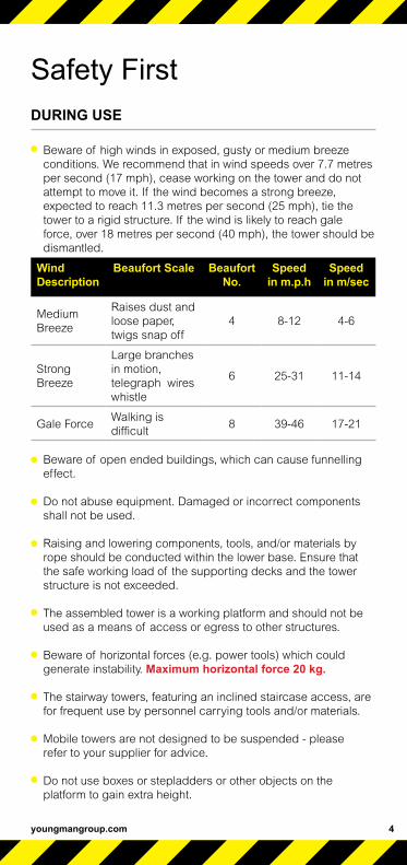
Beware of high winds in exposed, gusty or medium breezeconditions. We recommend that in wind speeds over 7.7 metresper second (17 mph), cease working on the tower and do notattempt to move it. If the wind becomes a strong breeze, expected to reach 11.3 metres per second (25 mph), tie the tower to a rigid structure. If the wind is likely to reach gale force, over 18 metres per second (40 mph), the tower should be dismantled.
Wind Description
Beaufort Scale Beaufort No.
Speed in m.p.h
Speed in m/sec
Medium Breeze
Raises dust and loose paper,twigs snap off
4 8-12 4-6
Strong Breeze
Large branches in motion, telegraph wires whistle
6 25-31 11-14
Gale ForceWalking is difficult
8 39-46 17-21
Beware of open ended buildings, which can cause funnelling effect.
Do not abuse equipment. Damaged or incorrect componentsshall not be used.
Raising and lowering components, tools, and/or materials byrope should be conducted within the lower base. Ensure thatthe safe working load of the supporting decks and the towerstructure is not exceeded.
The assembled tower is a working platform and should not beused as a means of access or egress to other structures.
Beware of horizontal forces (e.g. power tools) which couldgenerate instability. Maximum horizontal force 20 kg.
The stairway towers, featuring an inclined staircase access, are for frequent use by personnel carrying tools and/or materials.
Mobile towers are not designed to be suspended - pleaserefer to your supplier for advice.
Do not use boxes or stepladders or other objects on theplatform to gain extra height.
DURING USE
Safety First
4

BoSS Ladderspan User Guide
Safety First TIES
5
Ties should be used when the tower goes beyond its safeheight, beyond the limits of the stabilisers/outriggers, or ifthere is a danger of instability. They should be rigid, two wayties fastened to both uprights of the frame with load-bearingright angled or swivel couplers. Only couplers suitable for the50.8mm diameter tube of the tower should be used. Ideally,ties should be secured to both faces of a solid structure bymeans of anchorages.
The tie frequency may vary depending on the application, butthey should, at a minimum, be every 4 metres height.
For further information on tying-in a tower please contact yoursupplier or Youngman.
MAINTENANCE - STORAGE - TRANSPORT
All components and their parts should be regularly inspectedto identify damage, particularly to joints. Lost or broken partsshould be replaced, and any tubing with indentation greaterthan 5mm should not be used and put to one side formanufacture repair. Adjustable leg threads should be cleanedand lightly lubricated to keep them free running.
Brace claws, frame interlock clips, trapdoor latches andplatform windlocks should be regularly checked to ensure theylock correctly.
Refer to the BoSS Inspection Manual for detailed inspectionand maintenance advice
Components should be stored with due care to preventdamage.
Ensure components are not damaged by excessive strappingforces when transported.

6
Safety First
Horizontal Brace
4 Rung Frame
Side Toeboard
Platform (Fixed and
Trapdoor Decks)
Diagonal Brace
4 Rung Ladder FrameEnd Toeboard
Stabiliser
2 Rung Frame
Castor
Adjustable Leg2 Rung Ladder Frame

BoS
S 1
450
Ladd
ersp
an to
EN
100
4: A
vaila
ble
in 2
leng
ths
- 1.8
m a
nd 2
.5m
Inte
rnal
/Ext
erna
l Use
- To
wer
s un
der 2
.5m
are
out
side
of t
he s
cope
of E
N10
04
In
tern
al U
seCO
MPO
NEN
T
W
OR
KIN
G H
EIG
HT
(m)
PLAT
FOR
M H
EIG
HT
(m)
3.2
1.2
3.7
1.7
4.2
2.2
4.7
2.7
5.2
3.2
5.7
3.7
6.2
4.2
6.7
4.7
7.2
5.2
7.7
5.7
8.2
6.2
8.7
6.7
9.2
7.2
9.7
7.7
10.2
8.2
10.7
8.
7 11
.29.
211
.7
9.7
12.2
10.2
12
.710
.713
.2
11.2
13
.7
11.7
14
.212
.2
125/
150/
200m
m C
asto
r 4
4 4
4 4
4 4
4 4
4 4
4 4
4 4
4 4
4 4
4 4
4 4
Ad
just
able
leg
ass
emb
ly
4 4
4 4
4 4
4 4
4 4
4
4 4
4 4
4 4
4 4
4 4
4 4
1450
2 R
ung
Lad
der
Fra
me
1 1
1 1
1 1
1 1
1 1
1 1
1450
2 R
ung
Sp
an F
ram
e
1 1
1
1
1 1
1 1
1 1
1 1
1450
3 R
ung
Lad
der
Fra
me
1 1
1
1
1
11
11
11
1450
3 R
ung
Sp
an F
ram
e 1
1 1
1
1
1
11
11
1
1450
4 R
ung
Lad
der
Fra
me
1 1
1 2
1 2
2 3
2 3
3 4
3 4
4 5
4 5
5 6
5 6
1450
4 R
ung
Sp
an F
ram
e 1
1 1
2 1
2 2
3 2
3 3
4 3
4 4
5 4
5 5
6 5
6
1.8m
and
2.5
m F
ixed
Dec
k 1
1 1*
2
1 1
1 2
1 1
1 2
1 1
1 2
1 1
1 2
1 1
1
1.8m
and
2.5
m T
rap
Doo
r D
eck
1 1
1 1
2 2
2 2
3 3
3 3
4 4
4 4
5 5
5 5
6 6
6
1.8m
and
2.5
m H
oriz
onta
l Bra
ce (
red
) 6
6 6
6 10
10
10
10
14
14
14
14
18
18
18
18
22
22
22
22
26
26
26
2.1m
and
2.7
m D
iag
onal
Bra
ce (
blu
e)
2 3
3 4
5 6
7 8
9 10
11
12
13
14
15
16
17
18
19
20
21
22
23
IMP
OR
TAN
T: P
leas
e en
sure
you
als
o re
ad th
e Q
uant
ity S
ched
ule
on p
age
8.*
If y
ou a
re u
nab
le to
pos
ition
the
wor
king
pla
tform
eas
ily fr
om th
e g
roun
d, y
ou m
ay r
equi
re a
n ad
diti
onal
fixe
d p
latfo
rm fo
r th
is to
wer
he
ight
.
Quantity Schedule1450 Width Towers
7

8
Quantity Schedule1450 Width Towers
BoS
S 1
450
Ladd
ersp
an to
EN
100
4: A
vaila
ble
in 2
leng
ths
- 1.8
m a
nd 2
.5m
Inte
rnal
/Ext
erna
l Use
In
tern
al U
seCO
MPO
NEN
T
W
OR
KIN
G H
EIG
HT
(m)
PLAT
FOR
M H
EIG
HT
(m)
3.2
1.2
3.7
1.7
4.2
2.2
4.7
2.7
5.2
3.2
5.7
3.7
6.2
4.2
6.7
4.7
7.2
5.2
7.7
5.7
8.2
6.2
8.7
6.7
9.2
7.2
9.7
7.7
10.2
8.
2 10
.7
8.7
11.2
9.
2 11
.7
9.7
12.2
10
.2
12.7
10
.7
13.2
11
.2
13.7
11
.7
14.2
12.2
1.8m
and
2.5
m S
ide
Toeb
oard
2
2 2
2 2
2 2
2 2
2 2
2 2
2 2
2 2
2 2
2 2
2 2
1.2m
End
Toe
boa
rd
2 2
2 2
2 2
2
2 2
2 2
2 2
2 2
2 2
2 2
2 2
2 2
Toeb
oard
Hol
der
4
4 4
4 4
4 4
4 4
4 4
4 4
4 4
4 4
4 4
4 4
4 4
SP
7 Fi
xed
Sta
bili
ser
4 4
4 4
4 4
SP
10 T
eles
cop
ic S
tab
ilise
r 4
4 4
4 4
44
44
44
44
SP
15 T
eles
cop
ic S
tab
ilise
r 4
1.8m
TO
WE
R T
otal
Sel
f-w
eig
ht (
kgs)
91
99
10
3 14
6 16
1 16
9 17
5 19
5 21
0 23
1 23
7 25
7 27
2 27
9 30
0 30
6 32
0 32
8 33
4 35
4 36
9 37
7 38
3
2.5m
TO
WE
R T
otal
Sel
f-w
eig
ht (
kgs)
10
8 11
6 14
3 16
9 18
5 19
4 20
1 22
6 24
3 26
4 27
1 29
6 31
3 32
1 34
3 35
4 37
0 37
8 38
541
142
743
644
3
S
ee p
ages
10
and
30 fo
r st
abili
ser
pos
ition
s.

Quantity Schedule1450 Width Towers
The MAXIMUM SAFE WORKING LOAD (the combined weight ofthe users, tools and materials) that may be placed on the tower isthe total weight less the self weight of the tower. The total weightfor the towers shown in the schedule is 950kg.
Example 1:A 1450 tower built using the 3T method with a 4.2m platformheight and a platform length of 1.8m has a self weight of 175kg.
950kg — 180kg = 775kg maximum safe working load total weight self weight (users, tools and materials)
Example 2:A 1450 tower built using the 3T method with a 11.7m platformheight and a platform length of 2.5m has a self weight of 436kg.
950kg — 436kg = 514kg maximum safe working load total weight self weight (users, tools and materials)
For greater heights and loads, consult Youngman for guidance.
PLATFORM LOADING
On a 1450 tower a platform may comprise of a single deck or twodecks placed side by side. The maximum safe working load(the combined weight of the users, tools and materials) that maybe placed on a platform is 275kg. This must be evenly distributedover either one deck, or two decks placed side by side.
The quantities on pages 7 and 8, will enable BoSS towers to bebuilt safely and therefore comply with the requirements of theWork at Height Regulations. They include double guardrailsto all platforms, and toeboards will need to be added if any levelsare used as working platforms and for storage of materials. EN 1004 requires platforms at least every 4.2m, and these measures will exceed that requirement.
NUMBER OF WORKING PLATFORMS ALLOWED
9

youngmangroup.com
There is no requirement for ballast on 1450 towers if usingstabilisers as detailed in the table on page 8.
MOBILE OUTRIGGERS
MP16 outriggers can be used instead of SP15 stabilisers, asdetailed below. Mobile outrigger kits comprise:
Mobile Outrigger Kit
MP16 Mobile Outrigger 4
125/150/200mm Castor (Use same diameter castors as on tower)
4
250mm Adjustable leg 4
Plan Braces 4
The above components replace:
SP15 Stabiliser 4
STABILISERS
To improve rigidity, larger stabilisers can be used at a lower level than shown in the table on page 8.
Angle of Stabiliser 1450 TOWER
Double width 1450 Towers Dimension X Platform Length 1.8m Platform Length 2.5m
SP7 X= 3351 X= 3629
SP10 X= 4789 X= 5100
SP15 X= 5520 X= 5838
Stabiliser feet should form a square as shown in the diagram and table above.
Quantity Schedule1450 Width TowersBALLAST: Internal/External Use
10
X
X
90°
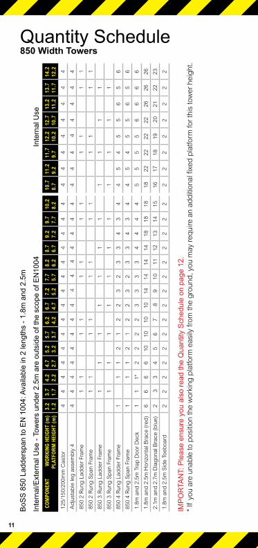
BoS
S 8
50 L
adde
rspa
n to
EN
100
4: A
vaila
ble
in 2
leng
ths
- 1.8
m a
nd 2
.5m
Inte
rnal
/Ext
erna
l Use
- To
wer
s un
der 2
.5m
are
out
side
of t
he s
cope
of E
N10
04
In
tern
al U
seCO
MPO
NEN
T
W
OR
KIN
G H
EIG
HT
(m)
PLAT
FOR
M H
EIG
HT
(m)
3.2
1.2
3.7
1.7
4.2
2.2
4.7
2.7
5.2
3.2
5.7
3.7
6.2
4.2
6.7
4.7
7.2
5.2
7.7
5.7
8.2
6.2
8.7
6.7
9.2
7.2
9.7
7.7
10.2
8.
2 10
.78.
7 11
.2
9.2
11.7
9.7
12.2
10
.212
.7
10.7
13
.211
.2
13.7
11
.7
14.2
12.2
125/
150/
200m
m C
asto
r 4
4 4
4 4
4 4
4 4
4 4
4 4
4 4
4 4
4 4
4 4
4 4
Ad
just
able
leg
ass
emb
ly 4
4
4 4
4 4
4 4
4 4
4 4
4
4 4
4 4
4 4
4
4 4
44
850
2 R
ung
Lad
der
Fra
me
1 1
1 1
1 1
1 1
1 1
1 1
850
2 R
ung
Sp
an F
ram
e 1
1 1
1 1
1 1
11
11
1
850
3 R
ung
Lad
der
Fra
me
11
11
11
11
11
1
850
3 R
ung
Sp
an F
ram
e
11
11
11
11
11
1
850
4 R
ung
Lad
der
Fra
me
1 1
1 2
1 2
2 3
2 3
3 4
3 4
4 5
4 5
5 6
5 6
850
4 R
ung
Sp
an F
ram
e 1
1 1
2 1
2 2
3 2
3 3
4 3
4 4
5 4
5 5
6 5
6
1.8m
and
2.5
m T
rap
Doo
r D
eck
1 1
1*
2 2
2 2
3 3
3 3
4 4
4 4
5 5
5 5
6 6
6 6
1.8m
and
2.5
m H
oriz
onta
l Bra
ce (
red
) 6
6 6
6 10
10
10
10
14
14
14
14
18
18
18
18
22
22
22
22
26
26
26
2.1m
and
2.7
m D
iag
onal
Bra
ce (
blu
e)
2 3
3
4 5
6 7
8
9 10
11
12
13
14
15
16
17
18
19 2
0 21
22
23
1.8m
and
2.5
m S
ide
Toeb
oard
2
2 2
2 2
2 2
2 2
2 2
2 2
2 2
2 2
2 2
2 2
2 2
IMP
OR
TAN
T: P
leas
e en
sure
you
als
o re
ad th
e Q
uant
ity S
ched
ule
on p
age
12.
* If
you
are
una
ble
to p
ositi
on th
e w
orki
ng p
latfo
rm e
asily
from
the
gro
und
, you
may
req
uire
an
add
ition
al fi
xed
pla
tform
for
this
tow
er h
eig
ht.
11
Quantity Schedule850 Width Towers

BoS
S 8
50 L
adde
rspa
n to
EN
100
4: A
vaila
ble
in 2
leng
ths
- 1.8
m a
nd 2
.5m
Inte
rnal
/Ext
erna
l Use
- To
wer
s un
der 2
.5m
are
out
side
of t
he s
cope
of E
N10
04
In
tern
al U
seCO
MPO
NEN
T
WO
RKI
NG
HEI
GH
T (m
) PL
ATFO
RM
HEI
GH
T (m
) 3.
2 1.
2 3.
7 1.
7 4.
2 2.
2 4.
7 2.
7 5.
2 3.
2 5.
7 3.
7 6.
2 4.
2 6.
7 4.
7 7.
2 5.
2 7.
7 5.
7 8.
2 6.
2 8.
7 6.
7 9.
2 7.
2 9.
7 7.
7 10
.2
8.2
10.7
8.
7 11
.2
9.2
11.7
9.
7 12
.2
10.2
12
.7
10.7
13.2
11
.2
13.7
11
.7
14.2
12.2
0.6m
End
Toe
boar
d 2
2 2
2 2
2 2
2 2
2 2
2 2
2 2
2 2
2 2
2 2
2 2
Toeb
oard
Hol
der
4 4
4 4
4 4
4 4
4 4
4 4
4 4
4 4
4 4
4 4
4 4
4
SP
7 Fi
xed
Sta
bilis
er
4 4
4 4
44
4
SP
10 T
eles
copi
c S
tabi
liser
4
4 4
44
4 4
44
44
44
SP
15 T
eles
copi
c S
tabi
liser
4
1.8m
TO
WE
R T
otal
Sel
f-wei
ght (
kgs)
72
79
10
6 12
6 13
9 14
6 15
1 17
2 18
6 20
4 21
0 23
024
325
0 27
0 27
6 28
9 29
6 30
1 32
1 33
5 34
1 34
7
2.5m
TO
WE
R T
otal
Sel
f-wei
ght (
kgs)
84
90
11
7 14
3 15
8 16
5 17
2 19
8 22
5 23
3 23
9 26
4 28
028
6 38
2 31
8 33
4 34
1 34
7 37
2 48
8 39
5 40
1
See
pag
es 1
4 an
d 30
for
stab
ilise
r p
ositi
ons.
Quantity Schedule850 Width Towers
12

The MAXIMUM SAFE WORKING LOAD (the combined weight ofthe users, tools and materials) that may be placed on the tower isthe total weight less the self weight of the tower. The total weightfor the towers shown in the schedule is 950kg.
Example 1:An 850 tower built using the 3T method with a 4.2m platformheight and a platform length of 1.8m has a self weight of 151kg.
950kg — 151kg = 799kg maximum safe working load total weight self weight (users, tools and materials)
Example 2:An 850 tower built using the 3T method with a 11.7m platformheight and a platform length of 2.5m has a self weight of 408kg.
950kg — 410kg = 540kg maximum safe working load total weight self weight (users, tools and materials)
For greater heights and loads, consult Youngman for guidance.
PLATFORM LOADING
On an 850 tower a platform comprises of a single deck only. Themaximum safe working load (the combined weight of the users,tools and materials) that may be placed on a platform is 275kg,evenly distributed over the deck.
The quantities on pages 11 and 12, will enable BoSS towers tobe built safely and therefore comply with the requirements of theWork at Height Regulations 2005. They include double guardrailsto all platforms, and toeboards will need to be added if any levelsare used as working platforms and for storage of materials. EN 1004 requires platforms at least every 4.2m, and these measures will exceed that requirement.
Quantity Schedule850 Width towersNUMBER OF WORKING PLATFORMS ALLOWED
13
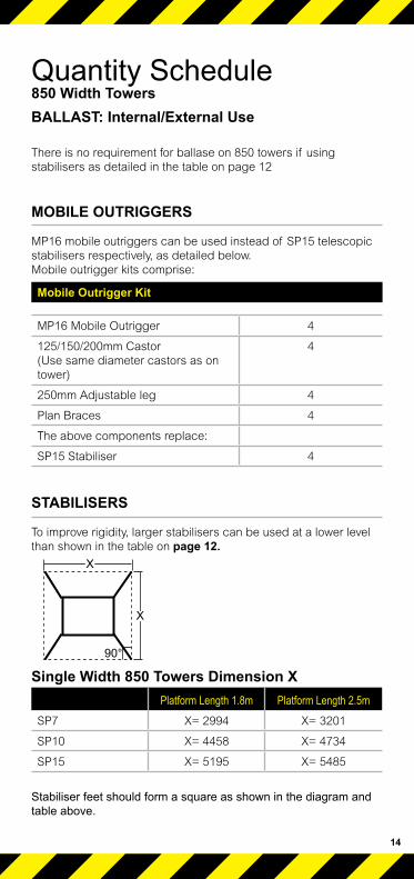
There is no requirement for ballase on 850 towers if using stabilisers as detailed in the table on page 12
MOBILE OUTRIGGERS
MP16 mobile outriggers can be used instead of SP15 telescopicstabilisers respectively, as detailed below.Mobile outrigger kits comprise:
STABILISERS
To improve rigidity, larger stabilisers can be used at a lower levelthan shown in the table on page 12.
Single Width 850 Towers Dimension XPlatform Length 1.8m Platform Length 2.5m
SP7 X= 2994 X= 3201
SP10 X= 4458 X= 4734
SP15 X= 5195 X= 5485
Stabiliser feet should form a square as shown in the diagram and table above.
Quantity Schedule850 Width TowersBALLAST: Internal/External Use
Mobile Outrigger Kit
MP16 Mobile Outrigger 4
125/150/200mm Castor (Use same diameter castors as on tower)
4
250mm Adjustable leg 4
Plan Braces 4
The above components replace:
SP15 Stabiliser 4
14
X
X
90°

When building a BoSS Tower:To comply with the Work at Height Regulations we showassembly procedures with platforms every 2 metres in height,and, the locating of guardrails in advance of climbing onto aplatform to reduce the risk of a fall.
All platforms feature double guardrails on both faces of eitherindividual platforms or fully decked levels.
All guardrails should be 1 and 2 rungs (0.5m and 1.0m) aboveplatforms.
Never stand on an unguarded platform positioned above the first rung of a tower. If your risk assessment shows it necessary, you may also need to guardrail platforms at this level.
Always start building with the smallest height frames atthe base of the tower:
Platform Heights in Metres Frame at base1.7, 2.2, 3.7, 4.2, 5.7, 6.2, 7.7, 8.2, 9.7, 10.2, 11.7, 12.2 2 rung
2.7, 4.7, 6.7, 8.7, 10.7 3 rung
1.2, 3.2, 5.2, 7.2, 9.2, 11.2 4 rung
Where all 3 frame heights are used in a tower, start with 2 rungframes at the base, with the 3 rung frames next and the 4 rungframes on the top. Refer to the quantity schedules for detail.
TO DISMANTLE A BOSS LADDERSPAN TOWER
Remove toeboards, and pass down the tower.
Unclip farthest end of braces and immediately go to protectedtrapdoor position on ladder to complete removal.
Remove upper platforms from protected platform levels below.
Pass removed components out of the tower to a colleague.
Assembly ProcedureMobile Towers - 3T Method ASSEMBLY AND DISMANTLING PROCEDURES
15

Safety ChecklistMobile Towers - 3T Method
CHECKLIST
16
Ensure all brace claws operate and lock correctly prior to erection
Inspect components prior to erection
Inspect tower prior to use
Tower upright and level
Castors locked and legs correctly adjusted
Diagonal braces fitted
Stabilisers/outriggers fitted as specified
Platforms located and windlocks on
Toeboards located
Check guardrails are fitted correctly. See illustration below.

Always start building with the smallest height frames at thebase of the tower:
Platform Heights in Metres Frame at base1.7, 2.2, 3.7, 4.2, 5.7, 6.2, 7.7, 8.2, 9.7, 10.2, 11.7, 12.2 2 rung
2.7, 4.7, 6.7, 8.7, 10.7 3 rung
1.2, 3.2, 5.2, 7.2, 9.2, 11.2 4 rung
Where all 3 frame heights are used in a tower, start with 2 rung frames at the base, with the 3 rung frames next and the 4 rung frames on the top. Refer to the Quantity Schedules for detail. The procedure illustrated shows 4.2m platform height tower startingwith a 2 rung frame.
Youngman recommend two persons are used to build BoSSTowers. Above 4m height, it is essential that at least twopersons are used. Only climb the tower from the inside.
1 Push castor into adjustable leg. Push Castor /adjustable leg assemblies into 2 rung span frame. Lock castors. Repeat
proceadure with 2 rung ladder frame.
It is recommended that for ease of levelling a gap of 50mm is left between the bottom of the leg and the adjustable nut. Adjustable Legs are for levelling only. You must not adjust all four to gain extra height.
NB: Base plates can be fitted to adjustable legs in lieu of castors if it is not necessary to move the tower.
Assembly ProcedureMobile Towers - 1450 3T Method ASSEMBLY FOR 1450 TOWERS
17

2 Fit one horizontal brace (red) onto the vertical of an span frame, just above the bottom rung, with the claw facing
outwards. The frame will now be self supporting.Note: All locking claws must be opened before fitting.
3 Position the ladder frame as shown and fit the other end of the horizontal brace on to the vertical, just above the bottom
rung. Fit a second horizontal brace between the bottom rungs on the other side of the frames to square the tower.
Assembly Procedure
18
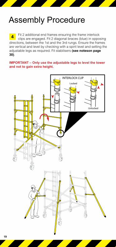
4 Fit 2 additional end frames ensuring the frame interlock clips are engaged. Fit 2 diagonal braces (blue) in opposing
directions, between the 1st and the 3rd rungs. Ensure the frames are vertical and level by checking with a spirit level and setting the adjustable legs as required. Fit stabilisers (see noteson page 30).
IMPORTANT – Only use the adjustable legs to level the tower and not to gain extra height.
Assembly Procedure
19

5 Fit a temporary deck on the lowest rungs. Fit a trapdoor deck on the 4th rung (2.0m) with the trapdoor next to the
ladder. Ensure the trapdoor is positioned with the hinges towards the outside of the tower as shown. Climb the ladder and, from theprotected trapdoor position, fit guardrails on the 5th and 6th rungs(in that order) on both sides of the platform.
Do not climb onto the deck until it is fully guardrailed.
When horizontal braces are fitted as guardrails, they should be 0.5m and 1.0m (1 and 2 rungs) above the platform level in allcases.
Remove the temporary deck from the lowest rung
Assembly Procedure
20

6 Fit the next pair of diagonal braces in opposing directions between the 3rd and 5th rungs add 2 additional end frames.
Assembly Procedure
7 Add two more diagonal braces between the 5th and 7th rungs. If finishing at this height (4.2m platform),reposition
the fixed deck to the 8th rung on the tower. Fit a trapdoor deck alongside it, with the hinges towards the outside of the tower, and the trapdoor next to the ladder. Add a single diagonal between the 7th and 9th rungs as shown. Climb up the ladder, and from the protected trapdoor position, fit the guardrails on the 9th and 10th rungs, in that order, on both sides of the tower.
21 BoSS Ladderspan User Guide

When building beyond a 4.2m platform height.
Continue to add pairs of end frames, diagonal braces and fit trapdoor decks as shown in the previous steps. Add
guardrails at 0.5m and 1.0m, (in that order), above theplatform from the protected trapdoor position. Do not climb onto the platform until it is fully guardrailed.
Continue until the required height is reached. Re-position the fixed deck to the required platform height and fit a trapdoor deck alongside it as shown in stage 7. Fit a single diagonal at the topof the tower as shown in stage 7. Fit the final guardrails as shownin stage 7.
Assembly Procedure
8
youngmangroup.com 22

7 Fit toeboards (see Instructions on page 29).The tower is now complete.
10 To take down the tower reverse the building sequence. When removing guardrail braces, unlock the 4 claws
furthest from the trapdoor and then return immediately to theprotected position within the trapdoor. You may then unlock theclaws at the other ends of the guardrails to remove them from thetower.
Assembly Procedure
Dismantling Procedure
23 BoSS Ladderspan User Guide

Always start with the smallest height frames at the base of the tower:
Platform height in Metres Frame at base.1.7, 2.2, 3.7, 4.2, 5.7, 6.2, 7.7, 8.2, 9.7, 10.2, 11.7, 12.2 2 Rung
2.7,4.7,6.7,8.7,10,7 3 Rung
1.2,3.2,5.2,7.29.2,11.2 4 Rung
Where all 3 frame heights are used in a tower, start with 2 rungframes at the base, with the 3 rung frames next and the 4 rungframes on the top. Refer to the quantity schedules for detail.
The procedure illustrated shows a 3.2m platform height tower starting with an 4 rung frame.
1 Insert adjustable leg/castor assemblies into end frames and lock the castors, see diagram Step 1 (page 17). Base plates
can be fitted to the adjustable legs if it is not necessary to move the tower. Fit 2 horizontal braces to the 850 end frames as shown in steps 2 and 3 for the 1450 tower procedure (page 18).
2 Fit a trapdoor deck on the 2nd rung. Fix the horizontal braces (red) as guardrails on the 3rd and 4th rungs (2 and 4
rungs above the platform) on both sides of the tower.
Assembly ProcedureMobile Towers - 850 3T MethodASSEMBLY FOR 850 TOWERS
24
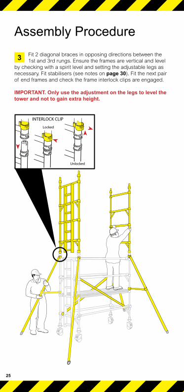
3 Fit 2 diagonal braces in opposing directions between the 1st and 3rd rungs. Ensure the frames are vertical and level
by checking with a spirit level and setting the adjustable legs as necessary. Fit stabilisers (see notes on page 30). Fit the next pair of end frames and check the frame interlock clips are engaged.
IMPORTANT. Only use the adjustment on the legs to level the tower and not to gain extra height.
25
Assembly Procedure
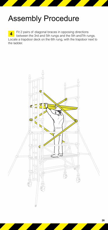
4 Fit 2 pairs of diagonal braces in opposing directions between the 3rd and 5th rungs and the 5th and7th rungs.
Locate a trapdoor deck on the 6th rung, with the trapdoor next to the ladder.
Assembly Procedure
26

5 Climb up the inside of the tower and from the protected position of the trapdoor, fit guardrails to the 7th and 8th
rungs, (in that order), on both sides of the tower.
Assembly Procedure
27

6 Continue the procedure until the required working height is reached, adding additional pairs of end frames, diagonal
braces and fitting trapdoor platforms, as shown on previous steps. At every platform level, add horizontal braces as guardrails from the protected position within the trapdoor, (as shown in step 5).
Fit a single diagonal at the top of the tower as shown.
Fit the toeboards (see instruction on page 29).
The tower is now complete.
Assembly Procedure
28
7 To take down the tower reverse the building sequence. When removing guardrail braces, unlock the 4 claws
furthest from the trapdoor and then return immediately to the protected position within the trapdoor. You may then unlock the claws at the other ends of the guardrails to remove them from the tower.
Dismantling Procedure

Lock yellow plastic toeboard clips over rung and deck claw asshown. Position as (A) on right hand deck claw. On other side ofthe working platform, position the clip as (B). Place 25mm thicktoeboards into slots in toeboard clips as shown.
ToeboardsMobile Towers - 3T MethodFITTING TOEBOARDS
29
Side Toeboard
End Toeboard
Toeboard Clip
Claw
Rung
(A)
(B)
Deck
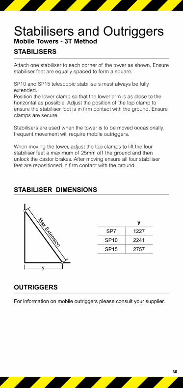
Attach one stabiliser to each corner of the tower as shown. Ensure stabiliser feet are equally spaced to form a square.
SP10 and SP15 telescopic stabilisers must always be fully extended.Position the lower clamp so that the lower arm is as close to the horizontal as possible. Adjust the position of the top clamp to ensure the stabiliser foot is in firm contact with the ground. Ensure clamps are secure.
Stabilisers are used when the tower is to be moved occasionally, frequent movement will require mobile outriggers.
When moving the tower, adjust the top clamps to lift the four stabiliser feet a maximum of 25mm off the ground and then unlock the castor brakes. After moving ensure all four stabiliser feet are repositioned in firm contact with the ground.
For information on mobile outriggers please consult your supplier.
Stabilisers and OutriggersMobile Towers - 3T Method STABILISERS
30
OUTRIGGERS
Max Extension
y
STABILISER DIMENSIONS
ySP7 1227
SP10 2241
SP15 2757

For further information aboutthis product or any otherproducts and services,please contact :
Youngman Group LtdThe Causeway, Maldon,Essex, CM9 4LJ,United Kingdom
t +44 (0)1621 745900f +44 (0)1621 859845e [email protected]
youngmangroup.comPart No: 032994 Date: 11/11
Youngman are members of: