mobile directional control valve - · pdf fileremote controlled, proportional spool actuators...
TRANSCRIPT

HV08 Mobile Directional Control ValveProportional, Load Sensing

Catalogue layoutThis catalogue has been designed to give an overview of the HV08 valve and to show how easily it can be customized to meet your needs. Apart from general information and basic technical data, the catalogue contains descriptions of the variety of options available for the different functions within the valve. After you have studied the options and made your selection, we will tailor your valve to meet your operating and control criteria.
Each function area is given as a subheading, followed by a brief description. When options are available for the function, an “Item number” in square brackets follows the subheading, e.g. Pressure relief valve [15]. This is followed by a series of coded options, e.g. PLS, PLB, PPS, PPB, Y1, together with a brief description of what each code represents. Alternatively, one or more pressure, flow or voltage options are given.
On page 11 is a general circuit diagram showing the basic functions of the HV08 valve, together with the item numbers or letters used to represent them. Naturally, the same item numbers or letters are used in all sub-circuit diagrams that appear else-where in the catalogue in conjunction with descriptions of the respective functions. All sub-circuit diagrams have been extracted from the general circuit diagram. Please note that, unless stated otherwise, all sections and views of the valves have been drawn as seen from the inlet section.
How to order your valveThe next step is to fill in a “Customer Specification Form” (CSF) to specify the options and characteristics you wish to be incorpo-rated into your valve. The CSF contains the same item numbers that appear in square brackets in this catalogue. To specify your valve, simply choose the common functions and spool-section specific options you require and enter the corresponding code or value into the box for the relevant item number in the CSF.
Should you require assistance completing the CSF, please do not hesitate to contact your nearest Parker representative, who will either help personally or refer you to the appropriate product specialist. The information in your CSF will be entered into our computerized valve specification program, which initi-ates the assembly process and generates a unique product ID
Conversion factors1 kg = 2.2046 lb1 N = 0.22481 lbf1 bar = 14.504 psi1 l = 0.21997 UK gallon1 l = 0.26417 US gallon1 cm3 = 0.061024 in3
1 m = 3.2808 feet1 mm = 0.03937 in9/5 °C + 32 = °F
Catalogue Information
number that is subsequently stamped into the data plate on your valve. Your valve specifications remain on our database to facili-tate rapid identification of your valve in the event of subsequent re-ordering or servicing matters.
Early consultation with Parker saves time and moneyOur experienced application engineers have in-depth knowledge of the different types of hydraulic system and the ways in which they work. They are at your disposal to offer qualified advice on the various combinations of functions and control characteristics you may require, and to advise how to obtain the best possible economy.By consulting Parker early in the project planning stage, you are assured of a comprehensive hydraulic system that will give your machine the best possible operating and control characteristics, together with outstanding economy.
Subject to alteration without prior notice. The graphs and diagrams in this catalogue are typical examples only. While the contents of the catalogue are updated continually, the validity of the information given should always be confirmed. For more detailed information, please contact Parker Hannifin.
FAILURE OR IMPROPER SELECTION OR IMPROPER USE OF THE PRODUCTS DESCRIBED HEREIN OR RELATED ITEMS CAN CAUSE DEATH, PERSONAL INJURY AND PROPERTY DAMAGE.
This document and other information from Parker-Hannifin Corporation, its subsidiaries and authorized distributors provide product or system options for further investigation by users having technical expertise.
The user, through its own analysis and testing, is solely responsible for making the final selection of the system and components and assuring that all performance, endurance, maintenance, safety and warning requirements of the application are met. The user must analyze all aspects of the application, follow applicable industry standards, and follow the information concerning the product in the current product catalog and in any other materials provided from Parker or its subsidiaries or authorized distributors.
To the extent that Parker or its subsidiaries or authorized distributors provide component or system options based upon data or specifications provided by the user, the user is responsible for determining that such data and specifications are suitable and sufficient for all applications and reasonably foreseeable uses of the components or systems.
Offer of SalePlease contact your Parker representation for a detailed ”Offer of Sale”.
WARNING – USER RESPONSIBILITY
2 Parker HannifinMobile Controls Division EuropeBorås, Sweden
Mobile Directional Control ValvesHV08
Catalogue HY17-8543/UK

Contents
Contents Page
General Information ........................................................................................................4Load-sensing systems (LS) ............................................................................................5Constant-pressure systems (CP) ...................................................................................6Constant-flow systems (CFC) .........................................................................................7
A. Series connection .................................................................................................8B. Parallel connection ...............................................................................................8
Keys ................................................................................................................................8Technical Data ................................................................................................................9Environmental characteristics .......................................................................................10Hydraulic Circuit Diagram .............................................................................................11Inlet Section ..................................................................................................................12
Type of inlet section [9]............................................................................................13Tank gallery.[10]......................................................................................................14Regulating spool (bypass).[11]................................................................................14No-load signal.[12]..................................................................................................15Pressure relief valve [15.–.17].................................................................................15Pressure relief valve.[15].........................................................................................15Pressure setting.[16]...............................................................................................15Tank connection T1.[18]..........................................................................................15Load-signal connection LSI.[20]..............................................................................15
End Section ..................................................................................................................16Load-signal system.[13]..........................................................................................16Tank connection T2.[19]..........................................................................................16Load-signal connection LSU.[21]............................................................................16
Spool Section ...............................................................................................................17Connections.[28].....................................................................................................17Spool actuators.[26]................................................................................18Hand-operated spool actuator with open spool end ...............................................18Lever bracket for spool actuators with open spool end ...........................................18ON/OFF remote controlled spool actuators with facility for operation by hand .......19Remote controlled, proportional spool actuators with closed spool end ................20Choice of Spool ......................................................................................................21Spool function.[22]..................................................................................................21Spool designation.[23].............................................................................................21Area relationship (cap).[24].....................................................................................21Options in the spool sections ..................................................................................22Accessories in the pressure gallery.[25].................................................................22Pressure limiters in the service ports .....................................................................23Port relief valve.[31].and.[33]..................................................................................23Pressure settings [32].+.[34]...................................................................................23
Function blocks .............................................................................................................24Levers ...........................................................................................................................24Dimensional Drawings ........................................................................................... 25-27
[00] Refers to item numbers in Customer Specification Form.
3 Parker HannifinMobile Controls Division EuropeBorås, Sweden
Mobile Directional Control ValvesHV08
Catalogue HY17-8543/UK

The HV08 is a load sensing, pressure compensated directional control valve intended for use in both load-sensing systems and constant-flow systems. The valve, which is stackable, is designed for many different applications in machines such as trucks, cranes, loaders and exca-vators.
Compact system constructionThe HVO8 is of modular construction and offers unique possibilities to integrate application-adapted function solutions into the valve to form a complete, compact system solution for the machine.
Freedom in machine designThe valve can be equipped for direct control by means of levers, or for electric, pneumatic or hydraulic remote control. Combinations of direct and remote control are also possible. These options give great freedom to the machine designer, since they enable the valve to be located ideally on the machine using the control medium best suited to the application in question.
EconomyThanks to modular construction, the HV08 can be optimized for both simple and complex functions. The possibility of inte-grating complete function solutions into the valve gives low overall system costs. The HV08 can be re-built or expanded at any time to meet changing demands. Moreover, by combining function-adapted solutions with load-sensing systems, energy consumption can be kept to a minimum.
DesignThe HV08 is stackable and can be supplied in combinations of 1 to 6 spool sections. It can also be supplied in combi-nation with function blocks, which are specially customized manifolds.
The valve is designed for system pressures up to 320 bar and can be equipped with port relief valves in the service ports for pressures up to 350 bar. The flow range is up to 300 l/min, depending on how the valve is equipped.
The valve is designed for use in systems with fixed or variable pumps.
Essential features and benefits• Modular construction: makes the HV08
very flexible, in that it is easy to re-build or expand the valve at any time to meet changing needs.
• Broad system compatibility: can be used in LS, CFC, CP and CPU sys-tems, thus giving you the freedom to choose the hydraulic system best suited to the machine and application in question.
• Good control characteristics: give precise control of the machine in both lifting and lowering movements.
• Can be equipped for both multi-pump and multi-valve systems: increases fur-ther the HV08’s range of applications in different types of hydraulic system.
• Can be flanged to specially customized function manifolds: enables the inte-gration of even more functions (even total system solutions) into a compact, single unit that does not require any extra external hoses or pipes, thus
making the installation simple, tidy and especially reliable.
• Wide range of spool actuators for ei-ther direct or remote control: enables the valve to be located in the most practical place on the machine. The range includes both hand-operated and remote-controlled spool actuators of different types, thus enabling the best combination of economy and con-trol characteristics to be obtained. The remote control system can be of the electric, pneumatic or hydraulic type.
• Individual load-hold check valves in each spool section: effectively prevent undesirable sinking of the load, thus improving operational safety.
• Individual port relief valves in each service port: enable port-specific limi-tation of maximum pressure to suit pre-cisely the respective functions being controlled.
• Quality and precision: quality materi-als and high manufacturing precision ensure a superior product with low internal leakage and long service life.
• Simplicity and serviceability: an em-phasis on simple design makes the HV08 easy to service.
General Information
4 Parker HannifinMobile Controls Division EuropeBorås, Sweden
Mobile Directional Control ValvesHV08
Catalogue HY17-8543/UK

Basic circuit diagram for LS system
Load-sensing systems (LS)In load-sensing systems, both pressure and flow are adapted according to demand. The HV08 controls pump displacement by means of a load signal, so that a constant pressure differential between the pump line and the signal line is obtained, i.e. the pump pressure is determined by the heaviest load controlled by the valve. While some suppliers and certain publications refer to CFC systems (see page 7) as load sensing, Parker reserves the LS denomination exclusively for systems that contain a variable pump and load-sensing valve.
Since load-sensing systems contain more complex control technology compared with constant-flow and constant-pressure systems, there are greater demands on the machine builder’s knowledge of control technology. The combination of high effi-ciency and good control characteristics require the main spools in the HV08 to be customized to the respective functions. As in constant-flow systems, simultaneously operated functions should have roughly the same pressure demands. If not, they should be divided into separate circuits so that optimal efficiency may be obtained. Mechanical construction should be rigid, since load-sensing systems can translate vibration in the construction into varying pressure demands, which can result in self-induced oscillation (hunting) in the system.
Load-signal systems can be built up in different ways. The HV08 is designed so that oil can circulate in the system without any oil being taken from the service ports, with the result that the pump reacts quickly even in cold weather. Even the pump regulators can be designed in different ways. Certain regulators consume no oil from the load-signal line, while others have a leakage restrictor that maintains a certain consumption. A third variant feeds oil into the load-signal line (a flow that must be drained off in a suitable way). The HV08 can be equipped with a built-in load-signal drainage facility that drains off approx. 1 l/min from the load-signal line, regardless of the pressure.
HV08-1
LS systems have outstanding characteristics when designed in the right way. For this reason, customers are advised to consult Parker for assistance with the design of the entire LS system, so that its advantages may be exploited in full.
Load sensing and pressure compensationThe pressure differential regulated by the pump regulator results in the flow to the heaviest load always being pressure compen-sated, i.e. the flow through the service port is independent of variations in the load pressure.
Functions can be pressure compensated in two ways. The first involves exploiting the effect of the flow forces on a hydraulic proportionally controlled (force controlled) valve spool. This gives simple and reliable function, with pressure compensation of both lifting and lowering movements, without the need for extra components. The second way is to equip each spool section with a compensator that maintains a constant pressure drop over the inlet restriction. This enables even directly controlled valves to be pressure compensated, but makes the valve more complex. The HV08 is pressure compensated though exploitation of the flow forces. See diagram on page 6. Parker does, however, make directional valves equipped with pressure compensators, e.g. our L and K series valves.
System Description (variable pump)
5 Parker HannifinMobile Controls Division EuropeBorås, Sweden
Mobile Directional Control ValvesHV08
Catalogue HY17-8543/UK

20 40 60 80 1000
100
150
200
250
50
0
Directly actuated spoolq(l/min) Flow rate in service port
Lever stroke in %
Hydraulically proportionally controlled spoolq(l/min) Flow rate in service port
Pressure compensated lift curve
300 bar lower150 bar50 bar
D-spool Q=250
Control characteristicsThe use of pressure-compensated spools in the HV08 helps to achieve good control characteristics.
When lowering a load at a speed higher than the available pump flow, great demands are placed on the replenishing char-acteristics of the valve. In the HV08, these demands are met by equipping the service ports of the valve with special anti-cavita-tion valves. To further improve the replenishing capabilities, a counter pressure valve can be placed in the tank outlet of the valve. In HV08 valves with closed spool actuators (PC and EHC), the spools are pressure compensated. The influence of the load on speed is therefore negligible. When more than one load-lifting function is operated simultaneously, it is the heaviest load that is pressure compensated.
Constant-pressure systems (CP)The distinguishing feature of a constant-pressure system is that the pressure is kept constant while the flow is varied according to demand.
The constant-pressure system is of simple construction. It employs a pump with variable displacement that is regulated to keep the pressure constant. The pump-regulating unit is simpler than the one in a load-sensing system. The constant-pressure system has outstanding control characteristics.
With the HV08, the control characteristics in constant-pres-sure systems are equal to those in load-sensing systems.
20 40 60 80 1000
100
150
200
250
50
0
Pressure compensated lift curve
300 bar lower150 bar50 bar
DPC-spool Q=250
Lever stroke in %
System Description (variable pump)
6 Parker HannifinMobile Controls Division EuropeBorås, Sweden
Mobile Directional Control ValvesHV08
Catalogue HY17-8543/UK
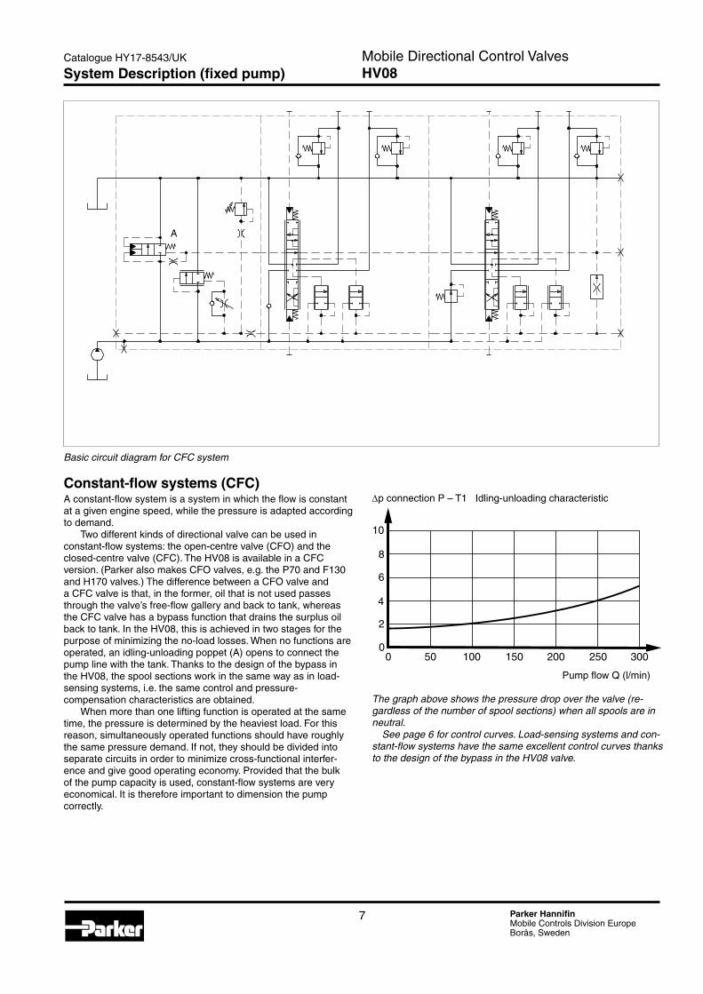
∆p connection P – T1 Idling-unloading characteristic
Pump flow Q (l/min)
The graph above shows the pressure drop over the valve (re-gardless of the number of spool sections) when all spools are in neutral. See page 6 for control curves. Load-sensing systems and con-stant-flow systems have the same excellent control curves thanks to the design of the bypass in the HV08 valve.
HV08-2
2
4
6
8
10
00 50 100 150 200 300250
Basic circuit diagram for CFC system
Constant-flow systems (CFC)A constant-flow system is a system in which the flow is constant at a given engine speed, while the pressure is adapted according to demand.
Two different kinds of directional valve can be used in constant-flow systems: the open-centre valve (CFO) and the closed-centre valve (CFC). The HV08 is available in a CFC version. (Parker also makes CFO valves, e.g. the P70 and F130 and H170 valves.) The difference between a CFO valve and a CFC valve is that, in the former, oil that is not used passes through the valve’s free-flow gallery and back to tank, whereas the CFC valve has a bypass function that drains the surplus oil back to tank. In the HV08, this is achieved in two stages for the purpose of minimizing the no-load losses. When no functions are operated, an idling-unloading poppet (A) opens to connect the pump line with the tank. Thanks to the design of the bypass in the HV08, the spool sections work in the same way as in load-sensing systems, i.e. the same control and pressure- compensation characteristics are obtained.
When more than one lifting function is operated at the same time, the pressure is determined by the heaviest load. For this reason, simultaneously operated functions should have roughly the same pressure demand. If not, they should be divided into separate circuits in order to minimize cross-functional interfer-ence and give good operating economy. Provided that the bulk of the pump capacity is used, constant-flow systems are very economical. It is therefore important to dimension the pump correctly.
A
System Description (fixed pump)
7 Parker HannifinMobile Controls Division EuropeBorås, Sweden
Mobile Directional Control ValvesHV08
Catalogue HY17-8543/UK

Connecting up the systemWhen a system contains more than one valve, it can be connected up in different ways. A few examples are given below.
A. Series connectionThe pump is connected to valve 1. Any flow not directed to a consumer by valve 1 continues to valve 2. This means that valve 1 has priority, i.e. in the event of full flow demand through valve 1, no flow continues to valve 2. See also [10] on page 14.
B. Parallel connectionIn parallel connection, one pump is connected to more than one valve in such a way that they all function as though they were a single valve.
KeyP = Pump connectionT1 = Tank connection T1T2 = Tank connection T2LSI = LS connection in inlet section (used only in series connection in LS systems)LSU = LS connection in outlet section (normally connected to the pump regulator, LS)a = Connection for idling unloading signal in inlet sectionb = Connection for idling unloading signal in end section
See page 12 for description of inlet section.
Inlet type BF IInlet type BF
Inlet type BF Inlet type BV
Inlet type BF Inlet type BV
Inlet type BV Inlet type BV
HV08-3
a T1 LSI P
LSU
b
T2
Spool section with outlet
Spool section(s)
Inlet section
Series connection, CFC
Series connection, LS
Parallel connection, CFC
Parallel connection, LS
System Description
8 Parker HannifinMobile Controls Division EuropeBorås, Sweden
Mobile Directional Control ValvesHV08
Catalogue HY17-8543/UK

PressuresPump connection max. 320 bar (4600 psi)Service port max. 350 bar (5000 psi)Tank connection, static max. 20 bar (290 psi)
Flow rate (recommended)Pump connection max. 300 l/min* (79 USgpm)Return from service port max. 250 l/min (66 USgpm)* Max. recommended flow rate is dependent on choice of spool.
Feed reducerAdjustment range 20 – 220 bar (290 – 3200 psi)
Internal pilot pressure25, 35 or 50 bar (applies to EHC spool actuator)(360, 500 or 725 psi approx.)
Leakage from service port over spoolFrom A or B port: max. 15 cm3/min at 100 bar, temperature 50 °C and viscosity 30 mm2/s (cSt).
Pilot-operated pressure relief valve [15]
Take-off of idling-unloading signal in inlet [12]
Pump connec-tion
Spool actuator [26]
Tank connection T1 [18]
Tank connection T2 [19]
Service port, A-port, section 1
Service port, B-port, section 2
Spool actuator [26]Connection for hydraulic remote control (PC). Actua-tion: pump to service port A. Note! The motor spools have reversed function, see page 21.
Connection for hydraulic remote control (PC). Actua-tion: pump to service port B. Note! The motor spools have reversed function, see page 21.
Inlet section [9]
Load-signal take-off in inlet, LSI [20]
Gauge port (pump pressure)
Load-signal take-off in end section, LSU [21]
Take-off of idling-unloading signal in outlet [12]
∆p (bar) Pressure-drop curves
q (l/min)
1 Pressure drop P – A/B with double-acting spool for 250 l/min.2 Pressure drop A/B –T1 with double-acting spool for 250 l/min.3 Pressure drop A/B –T1 with motor spool for 250 l/min.
5
10
00 50 100 150 200 250
1 2 3
Pressure drops
Technical Data
9 Parker HannifinMobile Controls Division EuropeBorås, Sweden
Mobile Directional Control ValvesHV08
Catalogue HY17-8543/UK

ConnectionsAll standard signal connections are available in two versions, un-less stated otherwise:
• G1/4 (BSP pipe thread) for flat seal (type Tredo) according to ISO 228/1
• 9/16-18 UNF-2B for O-ring seal according to SAE J1926/1
The pump, tank and service-port connections are available in three different versions: two split-flange types and a pipe-thread version.
• 1” flange plane according to SAE J518 standard pressure, but with M10 or UNC 3/8-16 fixing screws. Thread depth in both cases: 20 mm.
• BSP pipe-thread G1 for flat seal (type Tredo) according to ISO 228/1.
WeightWeight varies somewhat depending on the configuration of the valve. The details below are therefore approximate.
Complete valve Weight1 spool section 24 kg 53 lb2 spool sections 34 kg 75 lb3 spool sections 44 kg 97 lb4 spool sections 54 kg 119 lb5 spool sections 64 kg 141 lb6 spool sections 74 kg 163 lb
Technical Information
Environmental characteristicsThe valve is delivered painted with an anti-corrosion base paint. Steel parts subject to the risk of corrosion are protected by means of zinc-plating and yellow chromating, nitro-carburizing or similar. Certain spool actuators are supplied ready greased.
The O-rings in the valve are usually of nitrile rubber. For constant-pressure systems, however, we recommend that A30 [14] be selected to give O-rings of Viton in parting surfaces between the sections, since Viton withstands heat better than nitrile rubber. (Much heat is generated in constant-pressure systems that work hard.)
TemperatureOil temperature, working range +20 to + 90 °C (68 to 194 °F)*
FiltrationFiltration must be arranged so that Target Contamination Class 20/18/14 according to ISO 4406 is not exceeded. For the pilot circuit, Target Contamination Class 18/16/13 according to ISO 4406 must not be exceeded.
Hydraulic fluidsBest performance is obtained using mineral-base oil of high quality and cleanness in the hydraulic system.Hydraulic fluids of type HLP (DIN 51524), oil for automatic gear-boxes Type A and engine oil type API CD can be used.
Viscosity, working range 15-380 mm2/s**
Technical information in this catalogue is applicable at an oil viscosity of 30 mm2/s and temperature of 50 °C using nitrile rubber seals.
* Product operating limits are broadly within the above range, but satisfactory operation within the specification may not be accomplished. Leakage and response will be affected when used at temperature extremes and it is up to the user to deter-mine acceptability at these levels.
** Performance efficiency will be reduced if outside the ideal val-ues. These extreme conditions must be evaluated by the user to establish suitability of the products performance.
10 Parker HannifinMobile Controls Division EuropeBorås, Sweden
Mobile Directional Control ValvesHV08
Catalogue HY17-8543/UK

Diagram for basic functions shows HV08 in CFC version with two spool sections.
equipped according to the description below. For other equip-ment options, please see under respective function area [item number] further on in catalogue.
Item Code Description
1 CFC Valve configured for constant-flow system.
9 BF Inlet for fixed pump (CFC).
10 TO Open tank duct.
11 F1 Spring for 13 bar, ∆p P-LS.
12 X Inlet section equipped with idling-unloading poppet. In the end section, the connection for the idling-signal line is plugged and the signal line connected with tank.
13 LD Valve equipped with pressure-compensated load-signal drainage.
15 PLS Adjustable pilot-operated pressure relief valve ( controlled by pressure in load-signal line).
16 200 Pressure relief valve set at 200 bar.
18 T1 Tank connection T1 open.
19 T2B Tank connection in end section plugged.
20 LSIB Load-signal connection in inlet plugged.
21 LSUB Load-signal connection in end section plugged.
22 DPC Section 1 equipped with double acting, hydrauli-cally remote controlled spool for one double acting function.
EPCB Section 2 equipped with double-acting, hydraulically remote controlled spool. Absence of load signal (no tracer spool fitted on A-side) makes EPCB function single acting. Service port A is plugged.
The item numbers in the hydraulic circuit diagram above and in the columns below refer to different function areas for which different options can be selected. The valve above is
Item Code Description
23 PA Spool with code “PA” fitted.
24 0.7 Spool selected for section 1 is intended to control a hydraulic cylinder with area relationship 0.7.
25 N1 Section 1 equipped with check valve to prevent undesirable sinking of load.
MR Section 2 equipped with feed reducer to limit max. pressure.
26 PC2 Spool actuator for proportional remote control by means of pilot pressure.
28 8SM Service ports in split-flange version with metric fixing screws. Other connections in BSP pipe thread version.
31 PA Section 1 service port A protected against overload-ing and cavitation by combined port-relief and anti-cavitation valve.
Y2 No port-relief or anti-cavitation valve in section 2, service port A.
33 PA Section 1 service port B protected against overload-ing and cavitation by combined port-relief and anti-cavitation valve.
N2 Section 2 service port B protected against cavita-tion by anti-cavitation valve.
Tracer spool No tracer spool in case of E-function
HV08-5
T1
18
10 15, 16 31 33 31A B A B
12
20
LSIB
25 26 25 26
P1, 9 21
LSUB
13
12
T2B
19
33
2828 2626
22, 23, 24 22, 23, 24
11
Damping restrictor for bypass (load-up damping)
Hydraulic Circuit Diagram
11 Parker HannifinMobile Controls Division EuropeBorås, Sweden
Mobile Directional Control ValvesHV08
Catalogue HY17-8543/UK

HV08-13
HV08-12Inlet section type BF for systems with fixed pump
Inlet section type BV for systems with variable pump
The inlet section is available in two basic versions, one for pumps with fixed displacement and one for pumps with variable displace-ment. Both contain an adjustable, pilot-operated pressure relief valve. The inlet for fixed pumps also contains a bypass unit that drains surplus oil to tank, as well as an idling-unloading valve that reduces the Pump-to-Tank pressure when no functions are being
used. The bypass unit incorporates an adjustable restrictor that is used to set the response time on receipt of a signal.
Pump connectionTank connection T1 [18]
Pilot unit for pres-sure relief valve [15]
Idling-unloading poppet
Pump connectionTank connection T1 [18]
Open tank duct T0 [10]
Bypass unit regulating spool
Bypass spring [11]
Pilot unit for pres-sure relief valve [15]
Open tank duct T0 [10]
Pressure relief valve regulating spool
Control spring [11]
Load-up damping
Inlet Section
12 Parker HannifinMobile Controls Division EuropeBorås, Sweden
Mobile Directional Control ValvesHV08
Catalogue HY17-8543/UK

Type of inlet section [9]In addition to the aforementioned functions, the inlet sections contain connections for the pump, tank and various signals. A counter pressure nipple [10] can also be fitted in the inlet section.
BF Inlet section for systems with fixed pump (CFC).
BV Inlet section for systems with variable pump (CP, LS)
Inlet type BV.
HV08-6
Adjustable pilot control to maintain pressure limitation (PLS, PLB [15])
Idling-unloading poppet
Signal line for idling-unloading function
Bypass
Adjustable restrictor for load-up damping
Load-signal lineInlet type BF.
HV08-7
Adjustable pilot control to maintain pressure limitation (PPS, PPB [15])
Bypass
Load-signal line blocked
Inlet Section
13 Parker HannifinMobile Controls Division EuropeBorås, Sweden
Mobile Directional Control ValvesHV08
Catalogue HY17-8543/UK

Tank gallery.[10]The tank gallery in the inlet section can be equipped with a counter pressure valve to raise the pressure in the tank gallery to improve the replenishing characteristics (see items [31] and [33]). This function is particularly important in LS systems, in which the return flow should not be restricted too severely. The counter pressure valve is located in such a way that it does not raise the no-load losses in CFC systems.
Alternatively, a plug can be fitted to separate the T1 and T2 tank connections (see “Connecting up the system” on page 8).
PT Counter pressure valve in tank gallery. Tank line must always be connected to T1 connection [18].
SP Series connection plug – used in the first valve in series connection. T1 connection [18] connected to pump connection on subsequent valve. Tank connection T2 must be open.
T0 Open tank duct in inlet section. Normal version.
Regulating spool (bypass).[11]In the BF type inlet section [9], the bypass function consists of two parts; a no-load poppet and a regulating spool. When all spools are in neutral, the no-load poppet is open, i.e. the flow passes to tank with a low pressure drop. As soon as a spool is actuated, the no-load poppet closes and the regulating spool comes into force. The pressure drop over the regulating spool is determined by the heaviest load plus the spring force of the bypass. This means that the pump pressure will always be a few bar higher than what the heaviest load requires. By selecting a stronger spring, the pressure differential can be increased so that more flow can be obtained from the service port.
F1 Weak spring: gives pump pressure approx. 13 bar higher than load pressure. Gives nominal flow through service port.
F2 Strong spring: gives pump pressure approx. 19 bar higher than load pressure. Gives approx. 20% more flow through service port than F1.
F3 Extra strong spring: gives pump pressure approx. 25 bar higher than load pressure. Gives approx. 40% more flow through service port than F1.
F0 Without spring (normally not used).
PT – Counter pressure valve in tank gallery.
SP – Series-connection plug in tank gallery.
T0 – Open tank duct.
Inlet Section
14 Parker HannifinMobile Controls Division EuropeBorås, Sweden
Mobile Directional Control ValvesHV08
Catalogue HY17-8543/UK

∆p (bar) Pressure relief characteristic
q (l/min)
No-load signal.[12]When more than one valve is connected in parallel in CFC systems, the idling-unloading signal must be transmitted between the different valves. See “Connecting up the system” on page 8.
L No-load poppet in inlet section. Nipple for parallel connection fitted in end section. BF inlet only [9].
X No-load poppet in inlet section. Signal line connected with tank in end section. BF inlet only [9]. Normal version.
AO Signal connection in inlet open. In end section, signal line is connected with tank. BV inlet only [9]. Normal version.
AB Signal connection in inlet plugged. In end section, signal line is connected with tank. BV inlet only [9].
LA Signal connection in inlet open. Parallel connection nipple fitted in end section.
HV08-10
L – No-load poppet in inlet section. Nipple for parallel connection in end section.
X - No-load poppet in inlet section. Signal line connected with tank in end section.
AO – Signal line open in inlet section and connected with tank in end section.
AB – Signal line plugged in inlet section and connected with tank in end section.
LA – Signal line open in inlet section. Nipple for parallel connec-tion fitted in end section.
300
400
350
50
100
150
200
250
00 50 100 150 200 250 300 350
Pressure relief valve [15.–.17]The pressure relief valve is pilot operated, which gives it an excel-lent pressure characteristic. A small, adjustable, direct-acting pressure limiter pilot-controls the regulating spool [11]. The pilot flow is taken from either the pump line or the load-signal line. In systems in which it is possible to take the pilot pressure from the load signal, this option is recommended, since the pressure limiter cuts pressure peaks that are greater than the spring force of the regulating spool [11], regardless of the pump pressure. This gives more gentle regulation.
Pressure relief valve.[15]PLS Adjustable, pilot-operated pressure relief valve.
Controlled by pressure in load-signal line.
PLB Adjustable, sealed, pilot-operated pressure relief valve. Controlled by pressure in load-signal line.
PPS Adjustable, pilot-operated pressure relief valve. Controlled by pressure in pump line.
PPB Adjustable, sealed, pilot-operated pressure relief valve. Controlled by pressure in pump line.
Y1 Without pressure relief valve.
Pressure setting.[16]State the pressure at which you wish the pressure relief valve to be set.
Max. 250 bar for gray-iron version of valve.
Max. 320 bar for nodular-iron version of valve.
Tank connection T1.[18]T1 Tank connection T1 open. Normal version.
T1B Tank connection T1 plugged.
Load-signal connection LSI.[20]LSI Load-signal connection in inlet open. Only in case of
series connection in LS systems.
LSIB Load-signal connection in inlet plugged. Normal version.
Inlet Section
15 Parker HannifinMobile Controls Division EuropeBorås, Sweden
Mobile Directional Control ValvesHV08
Catalogue HY17-8543/UK

HV08-14Load-signal system.[13]The load-signal system consists of one tracer spool (load-sensing spool) per service port. The tracer spool also functions as a shuttle valve. It copies the load pressure, and the dominating signal is directed to the LSU connection [21] in the end section. See also diagram on page 8.
In the CFC version, the load signal goes to the bypass, which regulates the pressure in the pressure gallery to approx. 13, 19 or 25 bar above the load-signal pressure, depending on the choice of bypass spring - [11] page 14.
The load pressures from service ports A and B are directed to their respective tracer spools. If a single-acting spool function is required (EA or EB at item [22]), one of the tracer spools is removed. See diagram page 11.
The system permits a certain consumption in the load-signal line to the pump without affecting the load-signal level. This permits simpler system construction and the possibility of installing logic systems in the LS circuit. In the case of draining in the pump’s LS regulator, the system has better operating charac-teristics in winter, with quicker response times, since the oil in the LS circuit is always warm. Moreover, the system prevents disrup-tive micro-sinking of the load at the beginning of the lifting phase, since the signal oil is taken from the pump instead of the load. Since the tracer spools are two-way, it is necessary for the load signal to be “leaked off” continuously for the pump to be able to regulate when the load-signal pressure falls.
LD Pressure compensated load-signal drainage (gives approx. 1 l/min)
LB Blocked load-signal drainage.
LX Load-signal duct open to tank. Used in constant-pres-sure systems (CP/CPU).
Tank connection T2.[19]T2 Tank connection T2 open. Normal version.
T2B Tank connection T2 plugged.
Load-signal connection LSU.[21]LSU LS connection in end section open.
LSUB LS connection in end section plugged.
PC1 spool actuator [26] belonging to integrated spool section
Tank connection T2 [19]
Mounting plate
LD – Pressure compensat-ed load-signal drainage.
LB – Blocked load-signal drainage.
LX – Load signal open to tank.
End section viewed in direc-tion of inlet section.
HV08-11
Connection of signal for idling unloading [12]
Load signal connection LSU [21]
T2B
LSUB
The end section on the HV08 is integrated with a spool section. In addition to the functions of the spool section (see under “Spool section”), the end section contains load-signal drainage and connections for the tank, idling unloading and load signal.
End Section
16 Parker HannifinMobile Controls Division EuropeBorås, Sweden
Mobile Directional Control ValvesHV08
Catalogue HY17-8543/UK

The HV08 is stackable and can be supplied with 1-6 spool sections. Each spool section can be equipped individually with many different optional functions, spools and spool actuators, so that it can be customized optimally for the application and controlled function.
Spool sections come in two basic versions:
• single spool section for one spool
• single spool section combined with end section.
Spool sections are available in two different materials: gray iron for a max. pump pressure of 250 bar, or nodular iron for a max. pump pressure of 320 bar. To further assist machine builders, three different types of connection are available for the service ports in the HV08: two split-flange options (with different fixing screws) and a BSP pipe thread option.
Connections.[28]See also page 10.
8SM Service ports with 1” split-flange connections for M10 fixing screws. Other connections: G1/4.
8SU Service ports with 1” split-flange connections for 3/8-16 UNC fixing screws. Other connections: 9/16-18 UNF-2B.
8R Service ports with G1 threads. Other connections: G1/4.
Service port, B-port [28] Service port, A-port [28]
Tracer spool for copying of load pressure in service port B Machined control edges
Spool actuator [26]
Spool function [22]Spool designation [23]
Port relief valve, PA, port A [31]
Port relief valve, PA, port B [33]
Load-hold check valve, N1 [25]
A double-acting spool is shown, see page 21.
Spool Section
17 Parker HannifinMobile Controls Division EuropeBorås, Sweden
Mobile Directional Control ValvesHV08
Catalogue HY17-8543/UK

Spool actuators.[26]There are a number of different spool actuators for the HV08. They are divided into three groups: hand-operated, ON/OFF remote controlled and proportionally remote controlled.
Hand-operated spool actuator with open spool end
C Spring-centred spool actuator.
Steplessly operated spool actuator with spring-return to neutral.
Lever bracket for spool actuators with open spool end and facility for operation by hand
A09 All spool actuators with open spool end come with a lever bracket. The bracket is fitted in such a way that, when the operator pulls the lever toward him, the connection pump-to-service port A is opened. With the A09 option, however, the lever bracket is fitted upside down, so that the connection pump-to-service port B is opened when the operator pulls the lever toward him. Note! The motor spools have reversed function, see page 21. If the standard and A09 bracket options are used on the same valve, the levers will be of different heights. For this reason, such a combination is not recommended.
(Please see page 24 for details of the levers themselves.)
C
C + A09
HV08-15
Spool Section
18 Parker HannifinMobile Controls Division EuropeBorås, Sweden
Mobile Directional Control ValvesHV08
Catalogue HY17-8543/UK

HV08-19
ON/OFF remote controlled spool actuators with facility for operation by hand
AC2 Pneumatically remote-controlled ON/OFF spool actuator.
The AC2 is a pneumatically controlled ON/OFF spool actuator with spring centring and the possibility of local stepless control by means of a hand lever (optional).
Control pressure: min. 4 bar max. 10 bar.
Connection thread: G1/8 or NPTF 1/8-27
ACE2 Electro-pneumatically remote-controlled ON/OFF spool actuator.
The ACE2 is an electro-pneumatically controlled ON/OFF spool actuator with spring centring and the possibility of local stepless control by means of a hand lever (optional).
Primary air: 4-10 bar Control current: (12 VDC) min. 0.85 A (24 VDC) min. 0.42 A Voltage tolerance: ±20%
Connection thread: G1/8 or NPTF 1/8-27
ACE2F Electro-pneumatically remote-controlled ON/OFF spool actuator.
The ACE2F is identical to the ACE2 except that it has a common pressure gallery for primary air. The primary air can be connected to either the last or the first valve section that is equipped with an ACE2F spool actuator.
Connection thread: G1/8 or NPTF 1/8-27.
* Note! The motor spools have reversed function, see page 21.
AC2
ACE2
ACE2/ACE2F +A09
Connection, primary air
Actuation P-B, A-T*
Actuation P-A, B-T*
Actuation P-B, A-T*
Actuation P-B, A-T*
Actuation P-A, B-T*
Actuation P-A, B-T*
Connection, primary air
ACE2F
HV08-18
Spool Section
19 Parker HannifinMobile Controls Division EuropeBorås, Sweden
Mobile Directional Control ValvesHV08
Catalogue HY17-8543/UK

HV08-20
PC1 Hydraulic proportional spool actuator.PC2 The PC1 and PC2 are hydraulically, proportionally
controlled, spring-centred spool actuators. The PC1 is used for flows up to 100 l/min through the service port. For flows greater than this, the PC2 is used. The PC1 and PC2 are best controlled by the Parker PCL4 remote control valve (see separate brochure).
PC1 PC2
Breakaway pressure:* 5 bar 5 bar Final pressure:* 15 bar 25 bar (max. 35 bar) (max. 35 bar)
Connection thread: G1/4 or 9/16-18 UNF-2B.
PC1+ Indicates that PC1 or PC2 has been equipped withA13 adjustment screw for stepless limitation of spool PC2+ stroke length.A13
* The breakaway pressure and breakaway current refer to the pressure/current needed for the directional valve to open the connection “service-port to tank”.
The final pressure and final current are the lowest pressure/current needed to effect full actuation of a spool in the directional valve. This data must be taken into consideration when choosing pilot valves, since the opening pressure/current of the pilot valve must be lower than the breakaway pressure/current of the spool actu-ator in order to avoid jerky starting and stopping.
Moreover, the pilot valve’s final pressure/current must be higher than the final pressure/current of the directional valve to ensure that the directional valve can be fully actuated.
EHC1 Electro-hydraulic proportional spool actuator.EHC2 The EHC1 and EHC2 are electro-hydraulically, propor-
tionally controlled, spring-centred spool actuators. The EHC1 is used for flows up to 100 l/min through the service port. For flows greater than this, the EHC2 is used. The EHC1 and EHC2 are best controlled by means of a Parker electric remote-control system (see separate brochure). The Parker PVE102 is used as a pilot valve.
EHC1 EHC2Voltage: 12 V 12 V Breakaway current:* max. 360 mA max. 360 mA Final current:* min. 700 mA min. 1050 mA Pump pressure: max. 35 bar max. 35 bar Tank pressure: max. 15 bar max. 15 bar Solenoid (PVE102): max. 1250 mA max. 1250 mA 100% ED 100% ED Coil resistance at +20 °C: 7.2 ohms 7.2 ohms Inductance: 10 mH 10 mH
EHC1 EHC2Voltage: 24 V 24 V Breakaway current:* max. 220 mA max. 220 mA Final current:* min. 400 mA min. 600 mA Pump pressure: max. 35 bar max. 35 bar Tank pressure: max. 15 bar max. 15 bar Solenoid (PVE102): max. 680 mA max. 680 mA 100% ED 100% ED Coil resistance at +20 °C: 24.6 ohms 24.6 ohms Inductance: 32 mH 32 mH
Connection thread: G1/4 or 9/16-18 UNF-2B.
Actuation P-B, A-T**
Actuation P-A, B-T**PC1
PC2
EHC1EHC2
Actuation P-B, A-T**
Actuation P-A, B-T**
Spool-stroke limitationP-A, B-T**
Spool-stroke limitationP-A, B-T**
Spool-stroke limitationP-B, A-T**
Spool-stroke limitationP-B, A-T**
D101729
PC1/PC2
EHC1/EHC2
Remote controlled, proportional spool actuators with closed spool end
Mechanical adjustment of “breakaway pressure” P-A, B-T**
Mechanical adjustment of “breakaway pressure” P-B, A-T**
Mechanical adjustment of “breakaway pressure” P-A, B-T**
Mechanical adjustment of “breakaway pressure” P-B, A-T**
PVE102 pilot valve
** Note! The motor spools have reversed function, see page 21.
Spool Section
20 Parker HannifinMobile Controls Division EuropeBorås, Sweden
Mobile Directional Control ValvesHV08
Catalogue HY17-8543/UK

Cylinder area, B-portκ = Cylinder area, A-port
The spool is the most important link between the actions of the operator and the movement of the controlled function. Parker Hydraulics therefore goes to great lengths to optimize spools for different flows, load conditions, functions and applications. Since this is a continuous development process, new spools are being introduced all the time. For this reason, the many different spools available are not detailed in this catalogue. For assistance with the choice of spool therefore, please contact your nearest Parker representative.
Spool function.[22]Spools are divided into different groups, depending on their basic function.
D Double-acting spool for, e.g. double-acting cylinder. Blocked in the neutral position.
EA Single-acting spool for, e.g. single-acting cylinder. Blocked in the neutral position. Service port and tracer spool B blocked. See diagram page 11.
EB Single-acting spool for, e.g. single-acting cylinder. Blocked in the neutral position. Service port and tracer spool A blocked. See diagram page 11.
M Double-acting spool for, e.g. hydraulic motor. Service ports connected with tank (float position) in neutral. Note! The reversed flow direction at actuation compared to the other spool types.
S Double-acting spool for double-acting function. S spools are specially designed to handle light-load functions such as swing, slew, rotate, etc.
C Regenerative spool for rapid feeding of a cylinder, or for flow saving.
In addition to division into groups according to function, spools are grouped according to whether the spool end is open or closed. Spools with closed spool end are used for the PC1, PC2, EHC1 and EHC2 spool actuators and have the letters PC as a suffix to the spool designation. The following “PC-function spools” are available: DPC, EPCA, EPCB, MPC, SPC and CPC. Other spool actuators have spools with open spool end.
Spools with closed spool end are designed in such a way that the flow forces can be exploited to pressure-compensate the spool, i.e. when the load pressure or pump pressure changes, the flow to the service port remains almost unaffected. See page 6 for more information.
Spool designation.[23]Each spool has an imprinted letter code to facilitate identification during tuning or servicing in the field.
Area relationship (cap).[24]The area relationship, κ, for the section in question is calculated by dividing the cylinder area connected to service port B by the cylinder area connected to service port A. The spools for the HV08 are reversible and are installed in the valve according to the way in which the cylinder (the consumer) is connected to the valve. The value in [24] therefore determines the direction in which the spool is to be installed. When the large side of the cylinder is connected to the A-port, the area relationship is less than 1. The area relationship for a motor is 1.
HV08-21
D/S
A B
T P
EA
EB
M
C
Choice of Spool
21 Parker HannifinMobile Controls Division EuropeBorås, Sweden
Mobile Directional Control ValvesHV08
Catalogue HY17-8543/UK

Options in the spool sectionsAccessories in the pressure gallery.[25]The spool-section pressure gallery can be fitted with different accessories to give the best system construction.
O Without load-hold check valve.
N1 Load-hold check valve to prevent undesirable load sinking. Normal version.
MR Common feed reducer for service ports A and B fitted and factory-set at the desired pressure (from 20-220 bar at a flow of 10 l/min). The reduced pres-sure is practically independent of variations in either the primary pressure or the flow take-off. MR contains a load-hold function. MR limits the flow capacity of the spool to approx. 85% of the stated flow.
Feed reducers are used to limit the pressure from the valve when the section’s maximum pressure is below that of the main pressure relief valve, e.g. in the case of a clamping function. By using MR as a pressure limiter, energy losses can be kept down, since MR uses a pilot flow only. The pressure setting should be chosen so that it is as close as possible to the setting of the port relief valve, but at least 20 bar lower.
PR A prioritizing function that governs the section in the event of excessive flow take-off. It does this by limiting or stopping the flow to the spool section in which it is fitted.
Pred (bar) Feed reducers for service ports A and B
qm (l/min)
Pred = reduced pressure in service portqm = flow through service port
HV08-22
O - Pressure gallery open. N1 - Check valve in pressure gallery.
180
240
210
30
60
90
120
150
00 40 80 120 160
MR – Feed reducer in pressure gallery.
PR – Prioritizing valve in pressure gallery.
Spool Section
22 Parker HannifinMobile Controls Division EuropeBorås, Sweden
Mobile Directional Control ValvesHV08
Catalogue HY17-8543/UK

Pressure limiters in the service ports(port relief valves).[31]-[34]A specially designed cartridge valve is used as a port relief and anti-cavitation valve, PA, in the service ports. Its function is to protect the valve and consumer from pressure peaks and exces-sive pressure in the system. The very rapid opening sequence and good pressure characteristics make the cartridge valve an excellent port relief valve. The anti-cavitation valve causes oil to flow from the tank gallery to the service port side in the event of under-pressure in the service ports.
Port relief valve.[31].and.[33]X2 No port relief valve fitted. Service port connected to
valve’s tank gallery.
Y2 No port-relief or anti-cavitation valve fitted. Connection between service port and tank gallery blocked.
PA Combined port-relief and anti-cavitation valve PLC182 fitted. Valve is factory-set.
N2 Anti-cavitation valve only fitted.
Pressure settings [32].+.[34]Max. 280 bar for valves of gray iron (G at item [8]).Max. 350 bar for valves of nodular iron (S at item [8]).Optional standard settings: 40, 50, 63, 80, 100, 125, 140, 160, 175, 190, 210, 230, 250, 280, 300, 330 and 350 bar.
A
1 2
B
3 4
A B
In the diagram above, service port A is equipped with a combined port-relief and anti-cavitation valve PA (1) to limit the pressure and prevent cavitation. Service port B is fitted with an anti-cavitation valve N2 (2) to prevent cavitation.
In the diagram above, the connection between service port A and the tank is plugged, Y2 (3). This solution is used for spools with a single-acting function and in other cases when a connec-tion between the service port and tank is not required. Service port B is open to tank continuously, X2 (4).
Spool Section
50 100 150 200
100
00
200
300
400
50 100 150 200
8
00
16
4
12
∆p (bar) Pressure relief characteristics
∆p (bar) Anti-cavitation characteristics with PA or N2
q (l/min) q (l/min)
23 Parker HannifinMobile Controls Division EuropeBorås, Sweden
Mobile Directional Control ValvesHV08
Catalogue HY17-8543/UK

Function blocksFunction blocks (manifolds) can be flanged to the HV08 to enable total system solutions to be integrated into the valve. In addition to the standard units available, our experienced product and system designers can tailor function blocks to meet your needs exactly. For more information about total system solutions, please contact your local Parker representative.
The example opposite shows a specially customized function block mounted to a two-section valve in place of the end section. Like most Parker function blocks, it was constructed using cartridge valves, i.e. only the housing is a unique component.
LeversLevers are not supplied with the valve and must be ordered separately. The standard levers for HV08 valves are of steel, which is surface treated to give resistance to corrosion. Lever knobs are of black plastic, with a window under which a func-tion symbol can be inserted to illustrate the function of the lever. Levers are supplied complete with pin kits for mounting to the directional valve.
Lever: Ordering No.M8 (Window knob) 9126 1757 01
HV08-25
247
27
115 44
22
Ø27 (1.26)
(9.7
2)
(1.0
6)
(0.87)
(4.53)(1.73)
(inch)
Spool Section
24 Parker HannifinMobile Controls Division EuropeBorås, Sweden
Mobile Directional Control ValvesHV08
Catalogue HY17-8543/UK

Opens pump-to-service port B.Spool stroke 9.5 mm (0.37).
Opens pump-to-service port A.Spool stroke 9.5 mm (0.37).
C
AC2ACP2
ACE2
ACE2F
(inch)
* Note! The motor spools have reversed function, see page 21.
Dimensional Drawings
HV08-26
27
43 22
91 99 130
32
110
50 77 91
41
50 (1.97)
(1.9
7)
(3.0
3)
(3.5
8)
(1.6
1)
(1.0
6)
(1.6
9)
(0.8
7)
(4.3
3)
(1.2
6)
(3.5
8)
(3.9
0)
(5.1
2)
25 Parker HannifinMobile Controls Division EuropeBorås, Sweden
Mobile Directional Control ValvesHV08
Catalogue HY17-8543/UK

PC1PC2
EHC1EHC2
34
100
max
51 51 100
max
34
HV08-27
142
95 95
142
(1.3
4)
(1.3
4)
(3.9
4)
(3.9
4)
(2.0
1)
(2.0
1)
(5.59) (5.59)
(3.7
4)
(3.7
4)
(inch)
Dimensional Drawings
26 Parker HannifinMobile Controls Division EuropeBorås, Sweden
Mobile Directional Control ValvesHV08
Catalogue HY17-8543/UK

HV08-28
92
39
35 46 LSU
57127
82
166
Ø13 (4x) 41 41
35 (2x) 35 (2x)
16
60
122
62
92 92
93
77
L +
52
62
1016
L
(0.3
9)
(0.6
3)
(2.44)
(L +
2.0
5)
(3.66)
(3.03)
(0.51)
(1.61) (1.61)
(1.38) (1.38)(0.6
3)
(2.63)
(4.80)
(2.4
4)
(3.62) (3.62)
(3.6
2)
(3.2
3)
(6.5
4)
(1.54)
(1.38)(1.81)
(5.00)
(2.24)
No. of Resultant Lsections mm (inch)
1 176 (6.93)
2 238 (9.37)
3 300 (11.81)
4 362 (14.25)
5 424 (16.92)
6 486 (19.13)
Signal connection for idling unloading
Load-signal connection, LSI
Service port B, section 2
Tank connection, T1
Tank connection, T2 Signal connection for idling unloading
Pump connection, P
Service port A, section 1
20 (0.97) (LSI, idling unloading)
Load-signal connection, LSU
(inch)
Dimensional Drawings
27 Parker HannifinMobile Controls Division EuropeBorås, Sweden
Mobile Directional Control ValvesHV08
Catalogue HY17-8543/UK

© 2010 Parker Hannifin Corporation. All rights reserved. Catalogue HY17-8543/UK, POD, 11/2010, ZZ
Your local authorized Parker distributor
Parker Worldwide
EMEA Product Information CentreFree phone: 00 800 27 27 5374(from AT, BE, CH, CZ, DE, DK, EE, ES, FI, FR, IE, IL, IS, IT, LU, MT, NL, NO, PL, PT, RU, SE, SK, UK, ZA)
US Product Information CentreToll-free number: 1-800-27 27 537
www.parker.com
Ed
. 201
0-11
-16
Europe, Middle East, AfricaAE – United Arab Emirates, Dubai Tel: +971 4 8127100 [email protected]
AT – Austria, Wiener NeustadtTel: +43 (0)2622 23501-0 [email protected]
AT – Eastern Europe, Wiener Neustadt Tel: +43 (0)2622 23501 900 [email protected]
AZ – Azerbaijan, BakuTel: +994 50 2233 458 [email protected]
BE/LU – Belgium, NivellesTel: +32 (0)67 280 900 [email protected]
BY – Belarus, MinskTel: +375 17 209 9399 [email protected]
CH – Switzerland, EtoyTel: +41 (0)21 821 87 00 [email protected]
CZ – Czech Republic, KlecanyTel: +420 284 083 111 [email protected]
DE – Germany, KaarstTel: +49 (0)2131 4016 0 [email protected]
DK – Denmark, BallerupTel: +45 43 56 04 00 [email protected]
ES – Spain, MadridTel: +34 902 330 001 [email protected]
FI – Finland, VantaaTel: +358 (0)20 753 2500 [email protected]
FR – France, Contamine s/ArveTel: +33 (0)4 50 25 80 25 [email protected]
GR – Greece, AthensTel: +30 210 933 6450 [email protected]
HU – Hungary, BudapestTel: +36 1 220 4155 [email protected]
IE – Ireland, DublinTel: +353 (0)1 466 6370 [email protected]
IT – Italy, Corsico (MI)Tel: +39 02 45 19 21 [email protected]
KZ – Kazakhstan, AlmatyTel: +7 7272 505 800 [email protected]
NL – The Netherlands, OldenzaalTel: +31 (0)541 585 000 [email protected]
NO – Norway, AskerTel: +47 66 75 34 00 [email protected]
PL – Poland, WarsawTel: +48 (0)22 573 24 00 [email protected]
PT – Portugal, Leca da PalmeiraTel: +351 22 999 7360 [email protected]
RO – Romania, BucharestTel: +40 21 252 1382 [email protected]
RU – Russia, MoscowTel: +7 495 645-2156 [email protected]
SE – Sweden, SpångaTel: +46 (0)8 59 79 50 00 [email protected]
SK – Slovakia, Banská BystricaTel: +421 484 162 252 [email protected]
SL – Slovenia, Novo MestoTel: +386 7 337 6650 [email protected]
TR – Turkey, IstanbulTel: +90 216 4997081 [email protected]
UA – Ukraine, KievTel +380 44 494 2731 [email protected]
UK – United Kingdom, WarwickTel: +44 (0)1926 317 878 [email protected]
ZA – South Africa, Kempton ParkTel: +27 (0)11 961 0700 [email protected]
North AmericaCA – Canada, Milton, OntarioTel: +1 905 693 3000
US – USA, Cleveland (industrial) Tel: +1 216 896 3000
US – USA, Elk Grove Village (mobile) Tel: +1 847 258 6200
Asia PacificAU – Australia, Castle HillTel: +61 (0)2-9634 7777
CN – China, ShanghaiTel: +86 21 2899 5000
HK – Hong Kong Tel: +852 2428 8008
IN – India, MumbaiTel: +91 22 6513 7081-85
JP – Japan, FujisawaTel: +81 (0)4 6635 3050
KR – South Korea, SeoulTel: +82 2 559 0400
MY – Malaysia, Shah AlamTel: +60 3 7849 0800
NZ – New Zealand, Mt WellingtonTel: +64 9 574 1744
SG – Singapore Tel: +65 6887 6300
TH – Thailand, BangkokTel: +662 717 8140
TW – Taiwan, TaipeiTel: +886 2 2298 8987
South AmericaAR – Argentina, Buenos AiresTel: +54 3327 44 4129
BR – Brazil, Sao Jose dos Campos Tel: +55 12 4009 3500
CL – Chile, SantiagoTel: +56 2 623 1216
MX – Mexico, ApodacaTel: +52 81 8156 6000
VE – Venezuela, CaracasTel: +58 212 238 5422