mobile equipment - mistequay group€¦ · typical applications . con-vel. r. constant velocity...
TRANSCRIPT

Typical Applications CON-VELR Constant Velocity Joints are ideally suited for applications where unequal joint angles are encountered, and low vibration generation is needed. Typical industrial and mobile equipment applications for Constant Velocity Joints are: Industrial________________________ Mobile Equipment_______________________ -Steel Mills -Specialty Equipment -Paper Mills -Windmills -Dynamometers - Glass Manufacturing -Machine Tools Equipment Industrial Disc The CON-VELR Constant Velocity Joint is available in a disc design for stationary industrial applications. Connecting two rotating shafts, of almost any design, can be accomplished by selecting a coupling from the wide range of CON-VELR joints available. Our mid-slip or solid-shaft designs meet practically any coupling requirements. A variety of end-fitting configurations allow ease of installation and mounting.
-Steering Axles Military Vehicles -Marine Propulsion -Agricultural Equipment -Mining Machines -Construction Equipment -Railroad Equipment Bell Joint The original Rzeppa design is the basis for the CON-VELR Bell Joint. Designed specifically for all-wheel drive steering axle applications. Due to the true constant velocity characteristics at all angles, the CON-VELR Bell Joint provides improved tire wear. Low vibration generation reduces operator fatigue while increasing the life of the bearings and their supporting structures.
_____________________________________Table Of Contents_________________________________ Page Introduction 2 Products And Applications 3 Basic Information 4 Technical Features 5 Disc Joint Driveshafts 6-7 How to Select Driveshafts 8-9 Driveshaft Designs 10-11
Page Disc Joint Components 12-13 Bell-Type Joints 14-15 How To Select CV Joints 16-17 Bell Joint Family 18-19 Specifications 20-21 Engineering Information 22 Typical Applications 23
General Warnings
Heavy components should be handled carefully. If dropped they can cause serious bodily injury.
Consult CON-VEL Installation and Maintenance Bulletin for proper disassembly and assembly procedures.
Rotating driveshafts can be dangerous. All drive shafts should be covered with a shaftguard to prevent injury.
Disable all power sources (electrical, pneumatic, mechanical, etc.) before servicing equipment.
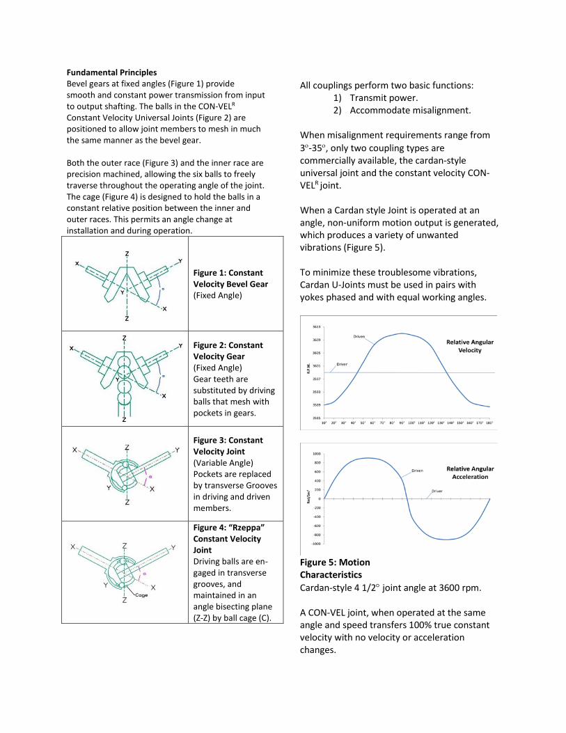
Fundamental Principles Bevel gears at fixed angles (Figure 1) provide smooth and constant power transmission from input to output shafting. The balls in the CON-VELR Constant Velocity Universal Joints (Figure 2) are positioned to allow joint members to mesh in much the same manner as the bevel gear. Both the outer race (Figure 3) and the inner race are precision machined, allowing the six balls to freely traverse throughout the operating angle of the joint. The cage (Figure 4) is designed to hold the balls in a constant relative position between the inner and outer races. This permits an angle change at installation and during operation.
Figure 1: Constant Velocity Bevel Gear (Fixed Angle)
Figure 2: Constant Velocity Gear (Fixed Angle) Gear teeth are substituted by driving balls that mesh with pockets in gears.
Figure 3: Constant Velocity Joint (Variable Angle) Pockets are replaced by transverse Grooves in driving and driven members.
Figure 4: “Rzeppa” Constant Velocity Joint Driving balls are en-gaged in transverse grooves, and maintained in an angle bisecting plane (Z-Z) by ball cage (C).
All couplings perform two basic functions:
1) Transmit power. 2) Accommodate misalignment.
When misalignment requirements range from 3ο-35ο, only two coupling types are commercially available, the cardan-style universal joint and the constant velocity CON-VELR joint. When a Cardan style Joint is operated at an angle, non-uniform motion output is generated, which produces a variety of unwanted vibrations (Figure 5). To minimize these troublesome vibrations, Cardan U-Joints must be used in pairs with yokes phased and with equal working angles.
Figure 5: Motion Characteristics Cardan-style 4 1/2° joint angle at 3600 rpm. A CON-VEL joint, when operated at the same angle and speed transfers 100% true constant velocity with no velocity or acceleration changes.

In reality it is difficult to maintain equal angles in today’s industrial and mobile equipment. Soft mounting of components, settling of foundations, movement due to loose bearings and end fitting tolerances all cause drive shaft angles to vary during operation and cause vibrations in the equipment. Cardan-style driveshafts generate troublesome vibrations three different ways:
1) Torsional excitation produced by non-uniform transmission of velocity of center member (Figure 5)
2) Internal excitation produced by the
oscillating torque loads of the driveshaft inertia being accelerated and decelerated.
3) Secondary couple excitation caused by the transmission of torque when operating a Cardan-style joint at an angle.
CON-VELR constant velocity joints and driveshafts solve the vibration problems generated by Cardan-style driveshafts. Features And Benefits CON-VELR Constant Velocity joints and driveshafts have no torsional or inertial excitations inherent in Cardan style driveshafts. The smooth torque transmitted from a CON-VELR driveshaft occurs even when the operating angles are unequal. The CON-VELR joints can successfully accommodate an unequal angle condition better than any other coupling device.
Figure 6: Secondary couple effect on support bearings, parallel output and input shafts. Secondary Coupling Force All couplings that transmit torque through an angle generate secondary coupling forces into the supporting structure. (Figure 6) In a CON-VELR Constant Velocity driveshaft, the secondary coupling forces react as static non-vibrating forces only. The magnitude of these couples are equal in both driving and driven shafts. For a given torque direction and joint angle, both couples are sensed in the same direction. The values of these secondary couples are:
𝐶𝐶1 = 𝐶𝐶2 = 𝑇𝑇 tan(𝜃𝜃2
)
Approximately 50% less secondary coupling force is generated with CON-VELR than with Cardan-style designs operating under the same conditions (Figure 7). This eliminates sinusoidal fluctuations that produce troublesome vibrations in equipment. The following graph clearly shows the CON-VELR advantage.

Figure 7
Torque = 1800 lb-in Angle = 6° T = Torque Transmitted By Joint θ = Joint Angle β = Angle Of Rotation Of Drive Yoke From Normal Position To The Plane Of The Joint Angle. Cardan Driver = T tan θ cos β = CDR
Cardan Driven = T tan θ cos β = CDN CON-VELR = T tan (θ/2) = C1 = C2 Industrial Disc The CON-VELR Constant Velocity Joint is available in a disc design for industrial applications. Connecting two rotating shafts, of almost any design, can be accomplished with a wide range of available CON-VELR mid-slip, tubular, or solid shaft designs. A variety of end-fitting configurations allow for easy installation and mounting.
The CON-VELR Disc Driveshaft is ideal for situations where high misalignment is possible due to movement of equipment during operation. Vibration problems caused by secondary coupling force of Cardan style joints can be virtually eliminated when replaced by CON-VELR Driveshafts.
Advantages • True constant velocity even with unequal angles • Low vibration generation • Low maintenance “single point lube” • Ease of installation • Smooth operation
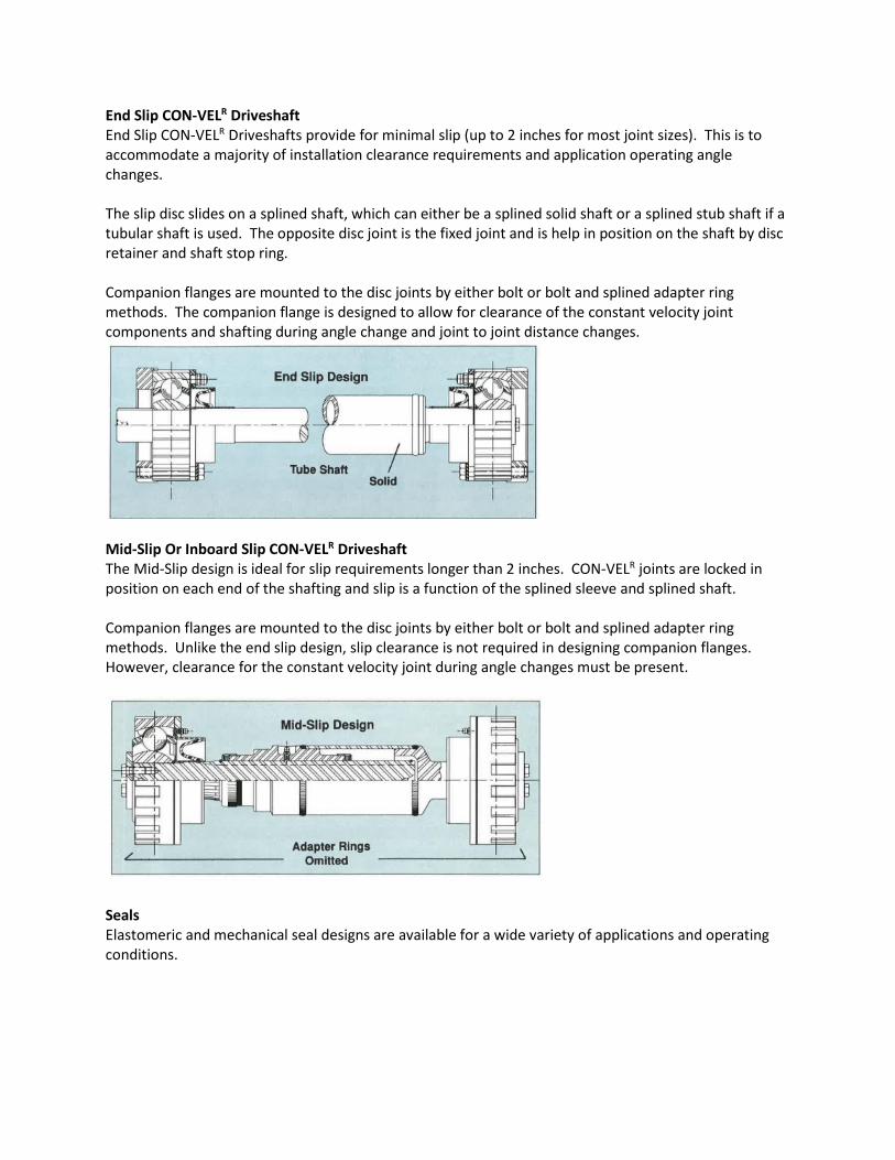
End Slip CON-VELR Driveshaft End Slip CON-VELR Driveshafts provide for minimal slip (up to 2 inches for most joint sizes). This is to accommodate a majority of installation clearance requirements and application operating angle changes. The slip disc slides on a splined shaft, which can either be a splined solid shaft or a splined stub shaft if a tubular shaft is used. The opposite disc joint is the fixed joint and is help in position on the shaft by disc retainer and shaft stop ring. Companion flanges are mounted to the disc joints by either bolt or bolt and splined adapter ring methods. The companion flange is designed to allow for clearance of the constant velocity joint components and shafting during angle change and joint to joint distance changes.
Mid-Slip Or Inboard Slip CON-VELR Driveshaft The Mid-Slip design is ideal for slip requirements longer than 2 inches. CON-VELR joints are locked in position on each end of the shafting and slip is a function of the splined sleeve and splined shaft. Companion flanges are mounted to the disc joints by either bolt or bolt and splined adapter ring methods. Unlike the end slip design, slip clearance is not required in designing companion flanges. However, clearance for the constant velocity joint during angle changes must be present.
Seals Elastomeric and mechanical seal designs are available for a wide variety of applications and operating conditions.

Selecting A CON-VELR Disc Joint Driveshaft* In order to select the proper CON-VELR Disc Joint Driveshaft for an application, the following information is required:
1) The maximum continuous horsepower or torque the driveshaft is expected to transmit. 2) The maximum speed at which the driveshaft will run. 3) The angle(s) at which the driveshaft is expected to operate on a continuous basis. 4) The MAXIMUM angle the driveshaft will see in operation AND at installation. 5) The total distance, or space, between flanges or shaft ends. 6) The duty cycle of the installation.
Example An induction motor, rated 50 hp at 1780 rpm, is driving a pinch roll at a 3:1 reduction. The pinch roll will operate continuously at angular displacements between 3° and 6° for about 8 hours per day. The distance between the output shaft of the reduction gear and the input shaft of the roll stand is 48 inches. Procedure 1) Identify the maximum continuous hp or
torque, speed, angular displacement and duty cycle.
50 hp, 6°, 8 hours/day for 5 days/week.
2) Determine the Torque Factor for speed at
angle (Table B). At 6° and 600 rpm, the Torque Factor is 0.88
3) Calculate the Application Load in lb-ft.
The Application Load equals:
𝐌𝐌𝐌𝐌𝐌𝐌𝐌𝐌𝐌𝐌𝐌𝐌𝐌𝐌 𝐂𝐂𝐂𝐂𝐂𝐂𝐂𝐂𝐌𝐌𝐂𝐂𝐌𝐌𝐂𝐂𝐌𝐌𝐂𝐂 𝐡𝐡𝐡𝐡 × 𝟓𝟓𝟓𝟓𝟓𝟓𝟓𝟓
𝐒𝐒𝐡𝐡𝐒𝐒𝐒𝐒𝐒𝐒
=𝟓𝟓𝟓𝟓 × 𝟓𝟓𝟓𝟓𝟓𝟓𝟓𝟓
𝟔𝟔𝟓𝟓𝟓𝟓 = 𝟒𝟒𝟒𝟒𝟒𝟒 𝐥𝐥𝐥𝐥 − 𝐟𝐟𝐂𝐂
4) Select the smallest CON-VELR Disc Joint size
(Table A) which will effectively carry the Application Load. Size E, with a continuous torque capacity of 663 lb-ft, is correct.
5) Determine the maximum operating speed
for the driveshaft. (Applies to steel shafting and tubing only.)
�𝟒𝟒.𝟒𝟒 × 𝟏𝟏𝟓𝟓𝟔𝟔� × 𝑺𝑺𝑺𝑺 × √𝐎𝐎𝐎𝐎𝟓𝟓 + 𝐈𝐈𝐎𝐎𝟓𝟓
𝐄𝐄𝐄𝐄𝟓𝟓
For a seamless tube of 3.0 OD, 0.25 wall thickness, and EL (effective length) of 44 inches, the maximum operating speed is:
�𝟒𝟒.𝟒𝟒 × 𝟏𝟏𝟓𝟓𝟔𝟔� × 𝟓𝟓.𝟔𝟔𝟒𝟒 × √𝟒𝟒.𝟓𝟓𝟓𝟓 + 𝟓𝟓.𝟓𝟓𝟓𝟓
𝟒𝟒𝟒𝟒𝟓𝟓 = 𝟔𝟔,𝟓𝟓𝟒𝟒𝟒𝟒 𝐫𝐫𝐡𝐡𝐌𝐌
6) Calculate the life in hours.
𝟏𝟏𝟓𝟓𝟓𝟓𝟓𝟓 × �𝟏𝟏𝟓𝟓𝟓𝟓𝟓𝟓𝐒𝐒𝐡𝐡𝐒𝐒𝐒𝐒𝐒𝐒�
× �𝐉𝐉𝐂𝐂𝐌𝐌𝐂𝐂𝐂𝐂 𝐓𝐓𝐂𝐂𝐫𝐫𝐓𝐓𝐌𝐌𝐒𝐒 𝐂𝐂𝐌𝐌𝐡𝐡𝐌𝐌𝐂𝐂𝐌𝐌𝐂𝐂𝐂𝐂 × 𝐓𝐓𝐂𝐂𝐫𝐫𝐓𝐓𝐌𝐌𝐒𝐒 𝐅𝐅𝐌𝐌𝐂𝐂𝐂𝐂𝐂𝐂𝐫𝐫
𝐀𝐀𝐡𝐡𝐡𝐡𝐥𝐥𝐌𝐌𝐂𝐂𝐌𝐌𝐂𝐂𝐌𝐌𝐂𝐂𝐂𝐂 𝐓𝐓𝐂𝐂𝐫𝐫𝐓𝐓𝐌𝐌𝐒𝐒 �𝟒𝟒
𝟏𝟏𝟓𝟓𝟓𝟓𝟓𝟓 × �𝟏𝟏𝟓𝟓𝟓𝟓𝟓𝟓𝟔𝟔𝟓𝟓𝟓𝟓
� × �𝟔𝟔𝟔𝟔𝟒𝟒 × .𝟒𝟒𝟒𝟒𝟒𝟒𝟒𝟒𝟒𝟒
�𝟒𝟒
= 5,909 hrs
7) Evaluate calculated life in hours to duty cycle to determine if the size selected provides hours needed to meet the applciation demand.
For this application, 8 hours per day x 5 days per week = 2,080 hours per year of operation. The “E” size Con-Vel at 5,909 hours life provides 2.8 years of service.
* Example is for preliminary sizing only. Contact CON-VELR engineering for final selection.
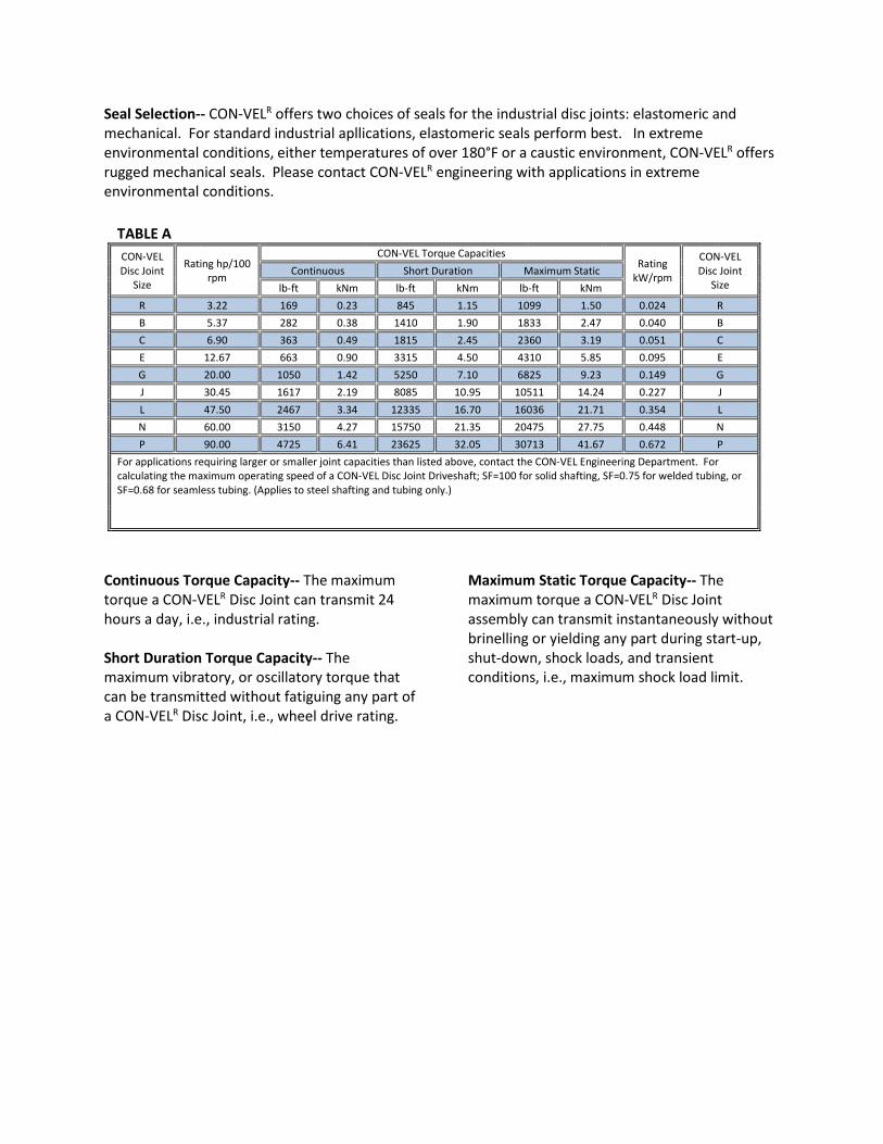
Seal Selection-- CON-VELR offers two choices of seals for the industrial disc joints: elastomeric and mechanical. For standard industrial apllications, elastomeric seals perform best. In extreme environmental conditions, either temperatures of over 180°F or a caustic environment, CON-VELR offers rugged mechanical seals. Please contact CON-VELR engineering with applications in extreme environmental conditions.
TABLE A CON-VEL
Disc Joint Size
Rating hp/100 rpm
CON-VEL Torque Capacities Rating
kW/rpm
CON-VEL Disc Joint
Size Continuous Short Duration Maximum Static
lb-ft kNm lb-ft kNm lb-ft kNm R 3.22 169 0.23 845 1.15 1099 1.50 0.024 R B 5.37 282 0.38 1410 1.90 1833 2.47 0.040 B C 6.90 363 0.49 1815 2.45 2360 3.19 0.051 C E 12.67 663 0.90 3315 4.50 4310 5.85 0.095 E G 20.00 1050 1.42 5250 7.10 6825 9.23 0.149 G J 30.45 1617 2.19 8085 10.95 10511 14.24 0.227 J L 47.50 2467 3.34 12335 16.70 16036 21.71 0.354 L N 60.00 3150 4.27 15750 21.35 20475 27.75 0.448 N P 90.00 4725 6.41 23625 32.05 30713 41.67 0.672 P
For applications requiring larger or smaller joint capacities than listed above, contact the CON-VEL Engineering Department. For calculating the maximum operating speed of a CON-VEL Disc Joint Driveshaft; SF=100 for solid shafting, SF=0.75 for welded tubing, or SF=0.68 for seamless tubing. (Applies to steel shafting and tubing only.)
Continuous Torque Capacity-- The maximum torque a CON-VELR Disc Joint can transmit 24 hours a day, i.e., industrial rating. Short Duration Torque Capacity-- The maximum vibratory, or oscillatory torque that can be transmitted without fatiguing any part of a CON-VELR Disc Joint, i.e., wheel drive rating.
Maximum Static Torque Capacity-- The maximum torque a CON-VELR Disc Joint assembly can transmit instantaneously without brinelling or yielding any part during start-up, shut-down, shock loads, and transient conditions, i.e., maximum shock load limit.

TABLE B Recommended Maximum Speed At Angle Torque Factor For Speed At
Angle Operating Angle
(Degrees)
Speed (rpm) For CON-VEL By Joint Series
R, B (rpm) C, E, G (rpm) J, L (rpm) N, P (rpm) <1000 rpm >1000 rpm
1 - 4 4000 3000 2500 2000 0.90 0.70 5 3500 2800 2200 1800 0.89 0.69 6 3000 2600 2100 1700 0.88 0.68 7 2800 2400 2000 1600 0.86 0.66 8 2500 2100 1850 1500 0.84 0.64 9 2200 1900 1650 1300 0.82 0.62
*10 2000 1700 1500 1200 0.80 0.60 *11 1800 1550 1350 1100 0.78 0.59 *12 1650 1400 1200 975 0.76 0.57 *13 1500 1200 1000 750 0.74 0.56 *14 1300 1050 800 650 0.72 0.54 *15 1200 950 700 550 0.70 0.53 *16 1100 850 600 500 0.68 0.51 *17 950 700 500 450 0.66 0.49 *18 800 600 450 400 0.64 0.48
* Mechanical seals recommended for continuous operation at these angles. Non-rotating elastomeric seals are also available for specific applications and operating conditions. Consult CON-VEL Engineering for information about special sealing and applications at speeds greater than those listed above.
The maximum operating angle of a CON-VELR Constant Velocity Disc Joint is 18°; however, in certain applications larger angles can be accomodated. Please contact CON-VELR with your requirements.

CON-VELR offers Constant Velocity Disc Joint Driveshaft assemblies in three configurations to meet a variety of operational considerations. Each self-supporting CON-VELR Disc Joint permits angular displacements up to 18°*, allowing a considerable amount of parallel offset between driving and driven equipment. Solid-Shaft Design-- Transmits power from one CON-VELR Disc Joint to another through a solid steel driveshaft. A slip spline at one end of the driveshaft provides length compenation for installation, removal, and operational considerations. Tubular-Shaft Design-- Transmits power from one CON-VELR Disc Joint to another through a tubular steel driveshaft. A slip spline at one end of the driveshaft provides length copmensation for installation, removal, and operational considerations. A driveshaft constructed of steel tubing can be designed to operate at rotational speeds much higher than those of a solid steel driveshaft. Mid-Slip Design-- Transmits power from one CON-VELR Disc Joint to another through a driveshaft consisting of a pair of coaxial shafts with a spline interface for length compensation. A mid-slip spline design is used in applications where a considerable amount of length adjustment is required. *Contact CON-VELR for operating angles greater than 18°.

CON-VELR Disc Joint Dimensions
Notes: 1) Turned, no splines. 2) Six holes equally spaced. 3) Clearance requirred to accommodate angular displacement of joint. 4) Steel seamless tubing DOM.
TABLE C
CON-VEL Disc Joint
Size
Disc Diameter & Length Number Of
External Splines
Face To Centerline Of Joint Bolt Pattern, Size & Number (2)
D1 L1 L3 BC D3 Number
in mm in mm in mm in mm in mm R 3.56 90.5 1.13 28.7 18 0.56 14.3 3.031 76.99 0.34 8.7 6 B 4.25 106.0 1.44 36.6 18 0.72 18.3 3.563 90.49 0.41 10.3 6 B 4.25 106.0 1.44 36.6 [1] 0.72 18.3 3.563 90.49 0.41 10.3 6 C 4.75 120.7 1.53 38.9 18 0.77 19.4 3.938 100.01 0.47 11.9 6 C 4.75 120.7 1.53 38.9 [1] 0.77 19.4 3.938 100.01 0.47 11.9 6 E 6.63 142.9 1.91 45.5 18 0.95 24.2 4.703 119.46 0.56 14.3 6 G 6.50 165.1 2.00 50.8 18 1.00 25.4 5.500 139.70 0.56 14.3 6 J 7.50 190.5 2.31 58.7 18 1.16 29.4 6.250 158.75 0.56 14.3 6 L 8.38 212.7 2.50 63.5 18 1.25 31.8 7.125 180.98 0.56 14.3 6 N 9.00 228.6 2.88 73.2 18 1.44 36.5 7.750 196.85 0.69 17.5 6 P 10.50 266.7 3.00 76.2 24 1.50 38.1 8.875 225.43 0.69 17.5 6
TABLE D
CON-VEL Disc Joint
Size
Clearance In Adapter (3) Solid Shaft (4) Diameter
Tubular Shaft (4) OD x Thickness CON-VEL
Disc Joint Size D2 L2 D4 D5
in mm in mm in mm in R 2.47 62.70 0.50 12.7 1.31 33.3 2.00 x 0.125 R B 2.81 71.40 0.50 12.7 1.31 33.3 2.25 x 0.188 B C 3.01 76.50 0.59 15.1 1.50 36.1 2.25 x 0.188 C E 3.75 95.30 0.59 15.1 1.69 42.9 3.00 x 0.250 E G 4.31 109.50 1.00 25.4 1.88 47.8 3.00 x 0.250 G J 5.00 127.00 0.91 23.0 2.13 54.1 3.75 x 0.438 J L 5.00 127.00 1.25 31.8 2.53 64.3 3.75 x 0.438 L N 6.25 158.80 1.13 28.6 2.75 69.9 5.00 x 0.500 N P 7.00 177.80 1.75 44.5 3.36 85.7 5.00 x 0.500 P

* Adapter Rings-- Available with a variety of hubs, bores and keyways. ** Seals-- Special seals are available upon request.
TABLE F
CON-VEL Disc Joint
Size
Tubing Size*** Locking Stub Shaft
Disc Assembly With Adapter Ring
CON-VEL Disc Joint
Size Elastomeric Seal Mechanical Seal
in 6 7 7 1
R 2.00 x 0.125 R2-52-41 R950572 -- R2-101-11 R
B 2.25 x 0.188 B2-52-161 B950057 -- B2-101-21 B
C 2.25 x 0.188 C3-52-191 C950530 -- C3-101-41 C
E 3.00 x 0.250 E3-52-91 E950418 E951498 E3-101-31 E
G 3.00 x 0.250 G4-52-581 G950196 G950359 G4-101-11 G
J 3.75 x 0.438 J5-52-241 J950137 J951024 J4-101-21 J
L 3.75 x 0.438 L5-52-201 L950034 L950605 L5-101-11 L
N 5.00 x 0.500 N6-52-131 N950052 N951065 N6-101-11 N
P 5.00 x 0.500 P7-52-41 P950020 P951203 P7-101-11 P
** Tubing Size-- CON-VELR provides steel seamless tubing DOM as standard.
TABLE E CON-VEL
Disc Joint Size
Adapter Ring*
Disc Assembly With Lockwasher Cap Screw Slip Stub Shaft CON-VEL
Disc Joint Size
Elastomeric Seal** Mechanical Seal** 1 2 2 3 4 5
R R2-101-11 R950573 -- 500357-10 500397-16 R2-52-191-4 R B B2-101-21 B950058 -- 500357-11 500196-20 B2-52-171-1 B C C3-101-41 C950531 -- 500357-12 500399-22 C3-52-201-2 C E E3-101-31 E950417 E951499 500357-13 500100-26 E3-52-81-2 E G G4-101-11 G950197 G950359 500357-14 500400-26 G4-52-221-5 G J J4-101-21 J950125 J951022 500357-15 500400-29 J4-52-251-1 J L L5-101-11 L950035 L950606 500357-16 990043-1 L5-52-211-3 L N N6-101-11 N950053 N951064 500357-17 500402-27 N6-52-121-1 N P P7-101-11 P950021 P951204 500357-18 990055-1 P7-52-21-3 P

Advantages Of Bell Type Joints: Low maintenance Compact design
Low vibration generation High angle capability Improved tire life
In open wheel drives, CON-VELR Bell Joints are equipped with elastomeric seals, or boots, which protect the Joints from environmental contamination while retaining the lubrication. CON-VELR Bell-Type Constant Velocity Joints will perform in either open or enclosed wheel drives. Enclosed steering axles provide CON-VELR Bell Joints with a continuous supply of lubrication and protection from contamination without requiring any additional sealing devices.

Selecting A CON-VELR Bell Joint For A Wheel Drive In order to select the proper CON-VELR Bell Joint for an application, the following information is required:
1) The maximum weight on the steering axle. 2) The rolling radius of the loaded wheel.
Example A 4X4 utility vehicle with a gross weight of 16,000 lbs has 6,000 lbs on the front axle. Steering angle is 25°, and the rolling radius of each wheel is 20 inches. Procedure
1) Calculate the weight on each steerable wheel:
𝑊𝑊𝑤𝑤 =𝑇𝑇𝑇𝑇𝑇𝑇𝑇𝑇𝑇𝑇 𝑊𝑊𝑊𝑊𝑊𝑊𝑊𝑊ℎ𝑇𝑇 𝑂𝑂𝑂𝑂 𝑆𝑆𝑇𝑇𝑊𝑊𝑊𝑊𝑆𝑆𝑊𝑊𝑂𝑂𝑊𝑊 𝐴𝐴𝐴𝐴𝑇𝑇𝑊𝑊
2
=6,000
2 = 3,000 𝑇𝑇𝑙𝑙
2) Identify the Rolling Radius of the steerable wheel.
𝑅𝑅𝑟𝑟 𝑊𝑊𝑖𝑖 𝑊𝑊𝑊𝑊𝑔𝑔𝑊𝑊𝑂𝑂 = 20 𝑊𝑊𝑂𝑂
3) Calculate the Wheel Slip Torque at the steerable wheel.
𝑇𝑇𝑤𝑤𝑤𝑤 =𝑊𝑊𝑤𝑤 × 𝑅𝑅𝑟𝑟
12 =3,000 × 20
12 = 5,000 𝑇𝑇𝑙𝑙 − 𝑓𝑓𝑇𝑇 Select the smallest CON-VELR Bell Joint Size (Table G) which will effectively carry the Wheel Slip Torque. Size G with a Short Duration Torque Capacity of 5,250 lb-ft is the correct selection.
Note: For 4×4 or 6×6 highway trucks with auxilary front drive, select a Bell Joint size using Short Duration Torque in Table G. For off-highway trucks, road machinery, tractors, and vehicles without inter-axle differentials, apply a service factor of 1.2 to 2.0, depending on vehicle design and use, to the Wheel Slip Torque before selecting a Bell Joint size from Table G, Short Duration Torque Capacity.
TABLE G CON-VEL
Bell Joint Size
Rating hp/100 rpm
CON-VEL Torque Capacities Rating
kW/rpm
CON-VEL Bell Joint
Size Continuous Short Duration Maximum Static
lb-ft kNm lb-ft kNm lb-ft kNm R 3.22 169 0.23 845 1.15 1099 1.50 0.024 R C 6.90 363 0.49 1815 2.45 2360 3.19 0.051 C D 9.29 488 0.66 2440 3.30 3172 4.29 0.089 D E 12.60 663 0.90 3315 4.50 4310 5.85 0.094 E G 20.00 1050 1.42 5250 7.10 6825 9.23 0.149 G J 30.80 1617 2.19 8085 11.00 10511 14.20 0.230 J L 47.00 2467 3.34 12335 16.70 16036 21.70 0.351 L N 60.00 3150 4.27 15750 21.40 20475 27.80 0.448 N
For applications requiring joints larger or smaller than the capacities listed above, contact CON-VEL Engineering.

Continuous Torque Capacity-- The maximum torque a CON-VELR Bell Joint can transmit 24 hours per day, i.e., industrial rating. Short Duration Torque Capacity-- The maximum oscillatory, or vibratory, torque that can be transmitted without fatiguing any part of a CON-VELR Bell Joint, i.e., wheel drive rating. Maximum Static Torque Capacity—The maximum torque a CON-VELR Bell Joint assembly can transmit momentarily during start-up, shut-down, shock loads, and transient conditions without brinelling ot yielding any part, i.e., maximum shock load rating.


Since our beginning in 1927, the Rzeppa Constant Velocity Joint has been solving problems for moblie equipment builders world wide. CON-VELR wheel-drive bell joints deliver thoroughly proven, dependable power transmission. Careful selection of the highest quality materials, precision manufactured by experienced craftsmen, conscientious assembly; and rigid adherence to detail guarantee a reliable, quality product.
TABLE H CON-VEL
Joint Series
Nominal Shaft Diameter (A)
Nominal Swing Diameter (B)
Face To Centerline Of Joint (C)
CON-VEL Joint
Series in mm in mm in mm
R 0.95 24.1 3.37 85.6 0.64 16.3 R C 1.25 31.8 4.43 112.5 0.76 19.3 C D 1.38 35.1 4.93 125.2 0.87 22.1 D E 1.50 38.1 5.25 133.4 0.95 24.1 E G 1.75 44.5 6.12 155.4 1.12 28.4 G J 2.00 50.8 7.12 180.8 1.25 31.8 J L 2.25 57.2 8.00 203.2 1.43 36.3 L N 2.50 63.5 8.62 218.9 1.43 36.3 N
With long-life high angle capability and high power density, the CON-VELR wheel drive joint offers greater performance than cardan designs. Contact CON-VELR engineering with your specific requirements.
The maximum operating angle of CON-VELR Constant Velocity Bell-Type Joints is 35°; however, in certain applications, larger angles can be accommodated.
* Disable all power sources (electrical, pneumatic, mechanical, etc.) before servicing equipment.
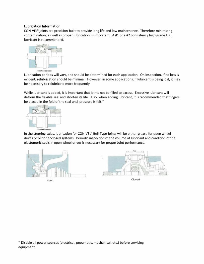
Lubrication Information CON-VELR joints are precision-built to provide long life and low maintenance. Therefore minimizing contamination, as well as proper lubrication, is important. A #1 or a #2 consistency high-grade E.P. lubricant is recommended.
Lubrication periods will vary, and should be determined for each application. On inspection, if no loss is evident, relubrication should be minimal. However, in some applications, if lubricant is being lost, it may be necessary to relubricate more frequently. While lubricant is added, it is important that joints not be filled to excess. Excessive lubricant will deform the flexible seal and shorten its life. Also, when adding lubricant, it is recommended that fingers be placed in the fold of the seal until pressure is felt.*
In the steering axles, lubrication for CON-VELR Bell-Type Joints will be either grease for open wheel drives or oil for enclosed systems. Periodic inspection of the volume of lubricant and condition of the elastomeric seals in open wheel drives is necessary for proper Joint performance.