mobile fluid power systems design - diva-portal.org370276/fulltext01.pdf · mobile fluid power...
TRANSCRIPT

Mobile Fluid Power SystemsDesign
with a Focus on Energy Efficiency


Linköping Studies in Science and Technology.Dissertations, No. 1339
Mobile Fluid Power SystemsDesign
with a Focus on Energy Efficiency
Björn Eriksson
Division of Fluid and Mechatronic SystemsDepartment of Management and Engineering
Linköpings UniversitetSE–581 83 Linköping, Sweden
Linköping 2010

ISBN 978-91-7393-304-9 ISSN 0345-7524
Copyright c© 2010 by Björn ErikssonDepartment of Management and Engineering
Linköping UniversitySE-581 83 Linköping, Sweden
Printed in Sweden by LiU-Tryck, Linköping, 2010.

To
my family

Abstract
This work deals with innovative energy efficient fluid power systems formobile applications. The subjects taken up concern to what extent and howenergy losses can be reduced in mobile working hydraulics systems. Vari-ous measures are available for increasing energy efficiency in these kinds ofsystems. Examples include:
Flow controlled systems The pump controller is switched from a load sens-ing to a displacement controlled one. The displacement is controlled inan open loop fashion directly from the operator’s demand signals. Thisreduces energy consumption at the same time as dynamic issues thatare attached to LS systems can be avoided.
Individual metering valve systems Flexibility is increased by removing themechanical coupling between the meter-in and meter-out orifices in di-rectional valves. An overview of this kind of system is given in thethesis. A design proposal that has been implemented is also presented.Initial test results are shown. Patents for this particular system havebeen applied for.
Displacement control Metering losses are reduced by removing the direc-tional valves. One pump is used for each load in such systems. Thishardware layout involves considerable changes compared to conven-tional systems. Displacement controlled systems are not studied in thiswork.
In mobile applications, overall efficiency is often poor and losses are substan-tial. The measures listed above can help improve this significantly in suchapplications. A flow dividing system can decrease energy consumption byabout 10% and an individual metering system by about 20%. Losses in pumpcontrolled systems are difficult to give a figure for; the losses are rather at-tached to the pumps and motors and not to the system layout. However,the losses for these systems are presumably even lower than for individualmetering systems. The main focus in this work is on individual metering sys-tems but questions about which components and so on are also treated. Forexample, the Valvistor valve concept has been studied as part of this work.
vii

Acknowledgements
The work presented in this thesis has been carried out at the Division ofFluid and Mechatronic Systems1 (Flumes) at Linköping University.
I would like to express my gratitude to several people. Thank you Prof. Jan-Ove Palmberg for your support, encouragement and for giving me this op-portunity to be a part of the division. You have been a great supervisor. I amalso very grateful to Prof. Bo R. Andersson. Thank you for the cooperationduring these years; it has been both useful and fun to discuss and exchangeideas with you. A special thank you also to Prof. Karl-Erik Rydberg. You havebeen a trusted colleague at the coffee breaks and I have learned a lot fromyour great knowledge and experience you have gladly shared. Thanks alsoProf. Petter Krus, the new head of the division, for enjoyably collaboration.Also, thank you to all the members and former members of the division! Youhave all made this time very exciting and I hope that we will continue to seeeach other in the future as well.
Thanks go to Parker Hannifin AB in Borås for their financial involvementin my work as well as for their help with hardware and other resources.Thank you Hans Boden and Marcus Rösth for your interest in my work andfor great company at various gatherings during these years. Thanks alsoJohan Hansson for your enjoyable collaboration in laborative work at Parkerin Borås.
Finally, I most of all would like to thank my family. Without my motherand father, Monica and Nils, this would not have been possible. Thank you somuch for everything. My greatest gratitude goes to you Ulrika, my wonderfullove, for all your support and for the gilt edge with which you frame my life.
Linköping in October 2010
Björn Eriksson
1The division name before 2010 was Division of Fluid and Mechanical Engineering Systems
ix

Papers
The following seven appended papers will be referred to by their Romannumerals. All papers are printed in their originally published state with theexception of minor errata and changes in text and figure layout.
In all papers the first author is the main author, responsible for the workpresented, with additional support from other co-writers. Papers [VII]and [X] are exceptions where the two first authors are the main authors,responsible for the work presented, with additional support from the co-writers.
[I] Eriksson B. and Palmberg J.-O., “Individual Metering Fluid PowerSystems: Challenges and Opportunities,” in Proceedings of the Institu-tion of Mechanical Engineers, Part I, Journal of Systems and Control Engi-neering, (accepted for publication).
[II] Eriksson B., Rösth M. and Palmberg J.-O., “A High Energy Effi-ciency Mobile Fluid Power System – Novel System Layout and Meas-urements,” in Proceedings of the Sixth International Fluid Power Confer-ence, IFK’08, pp. 103-114, Dresden, Germany, 31th March–2th April,2008.
[III] Eriksson B., Rösth M. and Palmberg J.-O., “Energy Saving Sys-tem Utilizing LQ-Technique Design,” in Proceedings of the Seventh In-ternational Conference on Fluid Power Transmission and Control, icfp’09,pp. 224-229, Hangzhou, China, 7th–10th April, 2009.
[IV] Eriksson B. and Palmberg J.-O., “How to Handle Auxiliary Functionsin Energy Efficient, Single Pump, Flow Sharing Mobile Systems,” inProceedings of the Seventh International Fluid Power Conference, IFK’10,pp. 65-78, Aachen, Germany, 22th–24th March, 2010.
[V] Eriksson B., Larsson J. and Palmberg J.-O., “A Novel Valve Con-cept Including the Valvistor Poppet Valve,” in ventil, Revija za FluidnoTehniko in Avtomatizacijo, pp. 450-457, October, 2008.
xi
[VI] Eriksson B., Andersson B. and Palmberg J.-O., “The Dynamic Prop-erties of a Poppet Type Hydraulic Flow Amplifier,” in Proceedings ofthe Tenth Scandinavian International Conference on Fluid Power, sicfp’07,pp. 161-177, Tampere, Finland, 21th–23th May, 2007.
[VII] Eriksson B., Nordin P. and Krus P., “Hopsan NG, A C++ Imple-mentation Using the TLM Simulation Technique,” in Proceedings of the51st International Conference of Scandinavian Simulation Society, sims’10,Oulu, Finland, 14th–15th October, 2010.
Patents
[VIII] Eriksson B., “Fluid Valve Arrangement,” PTC application numberwo2009005425, filed 2 July, 2007.
[IX] Eriksson B., “Fluid Valve Arrangement,” PTC application numberwo2009005426, filed 2 July, 2007.
Papers not included
The following papers are not included in the thesis but constitute animportant part of the background.
[X] Axin M., Braun R., Dell’Amico A., Eriksson B., Nordin P., Petters-son K., Staack I. and Krus P., “Next Generation Simulation SoftwareUsing Transmission Line Elements,” in Proceedings of Bath Workshop onPower Transmission and Motion Control, ptmc’10, pp. 265-276, Bath, UK,15th–17th September, 2010.
[XI] Eriksson B., Rösth M. and Palmberg J.-O., “An LQ-Control Ap-proach for Independent Metering Systems,” in Proceedings of theEleventh Scandinavian International Conference on Fluid Power, sicfp’09,CD publication, Linköping, Sweden, 2th–4th June, 2009.
[XII] Axin M., Eriksson B. and Palmberg J.-O., “Energy Efficient LoadAdapting System Without Load Sensing – Design and Evaluation,” inProceedings of the Eleventh Scandinavian International Conference on FluidPower, sicfp’09, CD publication, Linköping, Sweden, 2th–4th June,2009.
[XIII] Eriksson B., Andersson B. and Palmberg J.-O., “The Dynamic Per-formance of a Pilot Stage in a Poppet Type Hydraulic Flow Amplifier,”in Proceedings of the fifty-first ncfp Technical Conference, ifpe’08, pp. 659-668, Las Vegas, NV, 12th–14th March, 2008.
xii

[XIV] Eriksson B., Larsson J. and Palmberg J.-O., “A Novel Valve ConceptIncluding the Valvistor Poppet Valve,” in Proceedings of the Tenth Scan-dinavian International Conference on Fluid Power, sicfp’07, pp. 161-177,Tampere, Finland, 21th–23th May, 2007.
[XV] Eriksson B., Larsson J. and Palmberg J.-O., “Study on IndividualPressure Control in Energy Efficient Cylinder Drives,” in Proceedings ofFourth fpni - phD Symposium Sarasota 2006, fpni’06, pp. 77-99, Sarasota,FL, 13th–17th June, 2006.
xiii

xiv
Contents
1 Introduction 3
1.1 Background . . . . . . . . . . . . . . . . . . . . . . . . . . . . . . . . . . . . . . . . . . . . . . . . . . . . . . . . . . . . . . . . . . 3
1.2 Limitations . . . . . . . . . . . . . . . . . . . . . . . . . . . . . . . . . . . . . . . . . . . . . . . . . . . . . . . . . . . . . . . . . . . 5
1.3 Contributions . . . . . . . . . . . . . . . . . . . . . . . . . . . . . . . . . . . . . . . . . . . . . . . . . . . . . . . . . . . . . . . . 5
2 Review of Research and Technology 7
3 Aims 13
4 Methodology 15
5 Energy Efficient Mobile Systems 17
5.1 Potential Efficiency Improvements . . . . . . . . . . . . . . . . . . . . . . . . . . . . . . . . . . . . . . 18
5.1.1 Calculation Cases . . . . . . . . . . . . . . . . . . . . . . . . . . . . . . . . . . . . . . . . . . . . . . . . . . 19
5.1.2 Energy Efficiency Comparison . . . . . . . . . . . . . . . . . . . . . . . . . . . . . . . . . 20
5.2 Flow Controlled Systems . . . . . . . . . . . . . . . . . . . . . . . . . . . . . . . . . . . . . . . . . . . . . . . . . 22
5.2.1 Hardware . . . . . . . . . . . . . . . . . . . . . . . . . . . . . . . . . . . . . . . . . . . . . . . . . . . . . . . . . . . 24
5.2.2 A Demonstrator System . . . . . . . . . . . . . . . . . . . . . . . . . . . . . . . . . . . . . . . . . 24
5.3 Individual Metering Systems . . . . . . . . . . . . . . . . . . . . . . . . . . . . . . . . . . . . . . . . . . . . 26
5.3.1 Hardware . . . . . . . . . . . . . . . . . . . . . . . . . . . . . . . . . . . . . . . . . . . . . . . . . . . . . . . . . . . 26
5.3.2 Control . . . . . . . . . . . . . . . . . . . . . . . . . . . . . . . . . . . . . . . . . . . . . . . . . . . . . . . . . . . . . . . 30
5.3.3 A Demonstrator System . . . . . . . . . . . . . . . . . . . . . . . . . . . . . . . . . . . . . . . . . 33
5.4 Poppet Valves . . . . . . . . . . . . . . . . . . . . . . . . . . . . . . . . . . . . . . . . . . . . . . . . . . . . . . . . . . . . . . . 42
5.4.1 The Valvistor Valve Principle . . . . . . . . . . . . . . . . . . . . . . . . . . . . . . . . . . . 44
5.4.2 A Demonstrator Valve . . . . . . . . . . . . . . . . . . . . . . . . . . . . . . . . . . . . . . . . . . . . 48
6 Simulation Tools 49
6.1 Hopsan . . . . . . . . . . . . . . . . . . . . . . . . . . . . . . . . . . . . . . . . . . . . . . . . . . . . . . . . . . . . . . . . . . . . . . . 49
6.1.1 C++ and the Qt Framework . . . . . . . . . . . . . . . . . . . . . . . . . . . . . . . . . . . . . 50
6.1.2 Hopsan Core . . . . . . . . . . . . . . . . . . . . . . . . . . . . . . . . . . . . . . . . . . . . . . . . . . . . . . 50
6.1.3 Hopsan GUI . . . . . . . . . . . . . . . . . . . . . . . . . . . . . . . . . . . . . . . . . . . . . . . . . . . . . . . . 52
6.1.4 Scripting and Optimization . . . . . . . . . . . . . . . . . . . . . . . . . . . . . . . . . . . . . 53
1

Mobile Fluid Power Systems Design
7 Discussion and Conclusions 55
7.1 Flow Controlled Systems . . . . . . . . . . . . . . . . . . . . . . . . . . . . . . . . . . . . . . . . . . . . . . . . . 567.2 Independent Metering Systems . . . . . . . . . . . . . . . . . . . . . . . . . . . . . . . . . . . . . . . . . 577.3 The Valvistor Concept . . . . . . . . . . . . . . . . . . . . . . . . . . . . . . . . . . . . . . . . . . . . . . . . . . . . . 587.4 Hopsan NG – the New Generation Simulation Tool . . . . . . . . . . . . . . . 59
8 Outlook 61
9 Review of Papers 63
References 67
A Patents 75
A.1 Individual Metering System . . . . . . . . . . . . . . . . . . . . . . . . . . . . . . . . . . . . . . . . . . . . . . 76A.2 Bi-Directional Pressure Compensator Valve . . . . . . . . . . . . . . . . . . . . . . . . . . 77
Appended papers
I Individual Metering Fluid Power Systems 79
II A High Energy Efficiency Mobile Fluid Power System 111
III Energy Saving System Utilizing LQ-Technique Design 125
IV How to Handle Auxiliary Functions in Flow Sharing Systems 139
V A Novel Valve Concept Including the Valvistor Poppet Valve 155
VI The Dynamic Properties of a Poppet Type Flow Amplifier 169
VII Hopsan NG, A C++ Implementation Using the TLM Technique 191
2

1
Introduction
Fluid power is the technology of exploiting the properties of fluids to gen-erate, control and transmit power using flow and pressure of fluids. The fluidcan be of any kind. If it is a gas the technology is called pneumatics. If it is aliquid the technology is called hydraulics.
In the 17th century Blaise Pascal formulated Pascal’s law:
“Pressure exerted anywhere in a confined incompressible fluid istransmitted equally in all directions throughout the fluid.”
This was the birth of fluid power. Pascal also invented a hydraulic presswhich used hydraulic pressure to multiply force.
The first modern fluid power system first appeared in 1795 when theBritish engineer Joseph Bramah was granted a patent for a press invention [1].Bramah’s press was first used to compress soft bulky materials and later onit was also used to crush seeds to produce vegetable oil.
William George Armstrong, a British industrialist who invented the hy-draulic crane as well as the accumulator, and Joseph Bramah are consideredto be the fathers of the modern fluid power engineering field.
Burrows gives an overview of the early development of fluid power in [2].
1.1 Background
Fluid power systems are power generating and/or transmitting subsystems.They are used in a wide range of applications, mobile as well as industrial.In mobile machinery, fluid power is used for propulsion, working hydraulicsand auxiliary functions. The main reasons for preferring fluid power systemsto other technologies are:
3

Mobile Fluid Power Systems Design
Power density Fluid power components are superior in compactness toother technologies, compared for instance with electrical components.
Robustness Fluid power systems have the ability to handle force impactsbetter than, to for example, mechanical transmissions, which often con-tain fragile gears.
Cost For high power applications fluid power components are generallyavailable at lower cost compared to other technologies.
Working hydraulics in mobile fluid power systems often contain severaldifferent actuators. In most systems the actuators share one single pump.The need for only one system pump makes the fluid power system compactand cost-effective since the pump is a complex and expensive component.
A hydraulic load often consists of two ports, for example motors and cylin-ders. Such loads have traditionally been controlled by a directional valve thatcontrols the ports by one single control signal; the position of the main spool.With this kind of directional valve, the inlet (meter-in) and outlet (meter-out)orifices are connected mechanically. The mechanical connection makes thesystem robust and easy to control. But, at the same time, the system lacksflexibility. For example, there are a number of types of losses attached to thisconfiguration. These include losses due to simultaneously operated func-tions with different pressure demands. There are also unnecessary losses atmeter-out orifices since these are dimensioned for an over-running load. Thiscauses needless pressure losses when handling restrictive loads.
To overcome these shortcomings individual metering systems are an alter-native that can be applied. Independent metering is an umbrella term forsystems where the meter-in and meter-out orifices are independently con-trolled. This can be realised in different ways, which is a part of the scope ofthis work. By decoupling the meter-in and meter-out orifices a range of op-portunities open up. For example, the system can change flow paths duringoperation and recuperation and regeneration can be utilised to reduce energyconsumption. Recuperation is when oil is pressurised by external loads andthen fed back into the system. Regeneration is when both cylinder cham-bers (or motor ports) are connected to the pump line and the superfluouspressurised oil at the meter-out orifice is fed back to the pump line.
Energy saving aspects are among the main reasons for research on thiskind of systems, but there is also an opportunity for dynamic improvementscompared to conventional systems.
This thesis discusses the area of mobile working hydraulic systems withspecial attention to energy efficiency. Different types of systems are studiedwith the base in load sensing (LS) systems.
4
Introduction
1.2 Limitations
This thesis concerns the energy efficiency and dynamic characteristics of mo-bile fluid power systems only. The work is also limited to valve controlled work-ing fluid power systems only. For instance, propulsion systems are not treatedat all. Other system layouts, machine controlled or displacement controlled sys-tems, among others, are not studied. Aside from these system characteristics,other properties such as production considerations regarding manufacturingand marketing are not treated.
1.3 Contributions
A deeper understanding of mobile fluid power systems, how losses can bereduced in them and how this influences the dynamic properties is the mostimportant contribution of this thesis. A novel system layout utilizing a typeof bi-directional proportional poppet valve which is based on the Valvistorprinciple is proposed. A control strategy with restrictive use of sensors forthis system is studied and implemented in a demonstrator. A contributionto a new generation of simulation tool based on transmission line modelling(TLM) that can be used for real-time and optimization applications has alsobeen accomplished.
5


2
Review of
Research and
Technology
Energy efficiency has been an active research topic in the field of fluidpower for a long time.
The development of both hydraulic components and systems is controlledby demands from the market regarding controllability characteristics, sys-tem efficiency and flexibility. In certain applications, authority requirementsalso drive development. One example is the requirements concerning loadholding valves in applications where humans are present. A review of theresearch and technology in the field of mobile working hydraulic systems isgiven in this chapter.
Mobile working hydraulic applications are often designed in such a waythat more than one function is supplied from one single pump. The totalinstalled power at the consumer side, actuators such as cylinders and motors,is generally considerably higher than the installed power at the delivery side,the system pump. This is feasible because the actuators almost never requesttheir maximum power at the same time.
Demands from the market for better control properties, higher energy ef-ficiency and more flexible systems have pushed the development of mobileworking hydraulic systems toward load sensing (LS) systems. This is thestate-of-the-art today.
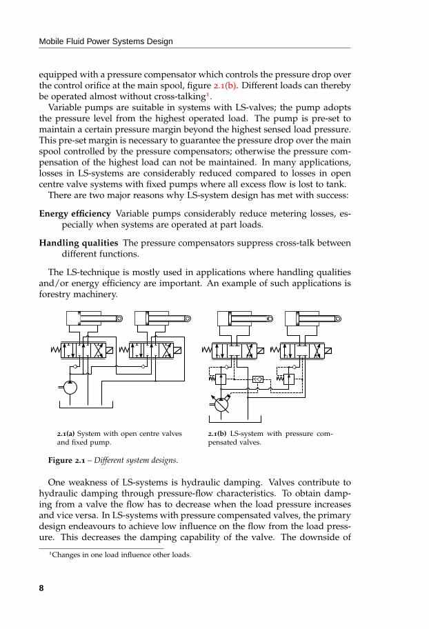
LS-systems are in various aspects often considered to have better controlproperties than for example open-centre systems, which are considered to bea proven, simple and robust system layout, figure 2.1(a). An LS-valve is often
7
Mobile Fluid Power Systems Design
equipped with a pressure compensator which controls the pressure drop overthe control orifice at the main spool, figure 2.1(b). Different loads can therebybe operated almost without cross-talking1.
Variable pumps are suitable in systems with LS-valves; the pump adoptsthe pressure level from the highest operated load. The pump is pre-set tomaintain a certain pressure margin beyond the highest sensed load pressure.This pre-set margin is necessary to guarantee the pressure drop over the mainspool controlled by the pressure compensators; otherwise the pressure com-pensation of the highest load can not be maintained. In many applications,losses in LS-systems are considerably reduced compared to losses in opencentre valve systems with fixed pumps where all excess flow is lost to tank.
There are two major reasons why LS-system design has met with success:
Energy efficiency Variable pumps considerably reduce metering losses, es-pecially when systems are operated at part loads.
Handling qualities The pressure compensators suppress cross-talk betweendifferent functions.
The LS-technique is mostly used in applications where handling qualitiesand/or energy efficiency are important. An example of such applications isforestry machinery.
2.1(a) System with open centre valvesand fixed pump.
2.1(b) LS-system with pressure com-pensated valves.
Figure 2.1 – Different system designs.
One weakness of LS-systems is hydraulic damping. Valves contribute tohydraulic damping through pressure-flow characteristics. To obtain damp-ing from a valve the flow has to decrease when the load pressure increasesand vice versa. In LS-systems with pressure compensated valves, the primarydesign endeavours to achieve low influence on the flow from the load press-ure. This decreases the damping capability of the valve. The downside of
1Changes in one load influence other loads.
8

Review of Research and Technology
this load independence feature is potential system dynamic issues, especiallyin closed loop control, see paper [IV].
The pump in the system shown in figure 2.1(b) is controlled in a closedloop, where the highest load pressure is the feedback signal. Two principalweaknesses with LS-systems are:
Oscillations Because of the pressure compensators, the system can be rela-tively undamped; low pressure-flow dependency2. In specific points ofoperation, LS-systems can thereby display oscillatory behaviour.
Pressure margin One reason to use a variable pump is to suppress flow andpressure losses. Nonetheless, there is a needless pressure loss in LS-systems, viz. the excessive pressure margin set by the pump controller.This margin is necessary to overcome the throttle losses between thepump and the directional valves. These losses are system dependentand change with external and internal conditions such as temperature,oil properties, hose lengths and so on. The pressure margin is often setsubstantially higher than necessary to ensure that it is high enough atall operational points.
The weaknesses of LS-systems have been the subject of extensive research.For example, Krus in [3] gives an analytical and systematic description ofLS-systems and their dynamics, including pump controllers.
Another research area is displacement controlled systems where one pumpis dedicated to each function, either as a transmission in a closed circuit [4] orin an open circuit [5–7]. Displacement controlled systems share the weaknessof low dampening with LS-systems since there is no pressure-flow depen-dency due to the lack of metering valves. This can be handled by adding ar-tificial damping with a pressure feedback, in this case to the electrical pumpcontroller. A practical implication of this is that the response demands on thepumps in these systems can be cumbersome.
Accumulator systems are used when energy is stored over time in hy-draulic systems. Liang and Virvalo [8] for example have done research onmobile fluid power systems using accumulators. There are also commercialproducts utilising accumulators, one of which was invented by Bruun [9].
An early broad overview of load sensing systems was published by An-dersson [10] in the early ’80s. An overview of energy efficiency fluid powersystems in particular is given by Rydberg in [11].
Most commercial mobile fluid power systems are still operated with opencentre valves and fixed pumps. The reason is that these systems have lowerinitial cost as well as being robust. Those properties are appreciated by in-dustry.
A step forward from the described LS-systems is to use another type ofpump controller.
2Flow should increase when the pressure drop increases through a valve to contribute addi-tional damping to the system.
9

Mobile Fluid Power Systems Design
The pump controller in an LS-system is designed to control the pressurelevel despite the flow demanded by the operator. Instead, it seems more nat-ural to control the pump flow rather then the pressure level. This can be doneby removing the LS feedback hose in figure 2.1(b) and controlling the pumpaccording to the total flow demand, see [12–16] and [IV, XII]. The challenge insuch a system is to match the valve signals to the pump displacement signalprecisely. This can be realized by changing the design of the compensatorsand using, for example, post-compensators. These types of compensator havebeen studied in [12] and [16].
Since there is no feedback signal to the pump in such systems, it is essentialto have knowledge about every flow consumer in the system. An exampleof unknown loads is when bodybuilders attach hydraulic systems to existingones. See [15] and [13].
The idea of controlling the pump without load feedback can also be utilizedin open centre valve systems with variable pumps, see [17] and [18].
The next step would be to decouple the meter-in and meter-out controlorifices in the valves. This has been a research topic since the late ’80s or early’90s. One of the first publications in the area is Jansson and Palmberg [19]where the idea of implementing a controller for four independent poppetvalves electrically was proposed.
In the literature, various terms are used for independent metering, amongthem programmable valves [20], multifunctional valves [21], individual meteringvalves [22, 23], and separate meter-in and meter-out control [24–26]. Some ofthem do not necessarily mean individual metering, but they are often usedas synonyms.
Individual metering systems can be split up into at least two categories:
Fixed flow paths Systems where the flow paths are similar to conventionalvalves. In these systems the main benefit of individual metering controlis lower metering losses, for instance at the meter-out element.
Variable flow paths Systems where the flow paths change during operation,for example when different modes are utilised such as “normal mode”,“high side regeneration mode”, “low side regeneration mode” and soon.
Already in the ’70s the former Swedish company Monsun-Tison had a sys-tem called monti, see figure 2.2 and [27–31]. This system was a pioneer inthe area of mobile hydraulics. The monti system was designed according tofour basic principles [27]:
1. The valve functions control flow rate independently of pressure andload.
2. The valve units controlling the flow and direction are located on theactuators themselves and contain all the necessary supplementary de-vices, such as pressure relief, anti-cavitation and hose break valves.
10

Review of Research and Technology
To control
station
Main lines
2.2(a) monti system layout, dis-tributed valves at the cylinders. (Fig-ure from [27].)
Cylinder (Motor)
To pressure control valve
Stem line P
Stem line S
Stem line T
From auxiliary
functions
Main pump
Shunt valve
Flow controlled
directional valve,
distributed on cylinder
2.2(b) Example of the monti systemwith fixed pump configuration, moredetailed than figure 2.2(a). (Simplifiedfigure from [28].)
Figure 2.2 – Layout of the monti system. This individual metering system was intro-duced in the mid-70s.
Valve sizes are related to the individual actuators; different sizes canbe used in the same system.
3. The valves control the pressure in the system to correspond to the re-quirements of the heaviest load. For fixed displacement pumps, thisis done by means of a special bypass valve; for variable displacementpumps, by regulation of the displacement. The system thus never op-erates at a higher pressure than is necessary.
4. All these main valves are remotely controlled, either by a hydraulicpilot system or by an electrohydraulic system.
The system was not able to handle mode switches like modern individ-ual metering systems. Among the stated advantages were good manoeuvreproperties, a smoother learning process for operators and no need for hoseburst valves thanks to the valve distribution [30].
Another independent metering valve was developed in the U.S. in the ’80s,called CMX [32]. It was also an early independent metering system. It has aspool valve at meter-in and poppet valves at meter-out. The valve includes aload-drop check valve, load sensing valve and relief valves. The CMX is ofthe sandwich type and sections can be stacked into a bank supplying severalloads.
11

Mobile Fluid Power Systems Design
Advanced electrical controllers utilising different metering modes first ap-peared in the late ’90s. One of the first publications on individual meteringsystems in that sense is Jansson and Palmberg [19]. Ever since then interestin this topic has been growing in academia as well as in industry.
One of the first modern individual metering systems showed up in thelate ’90s [33]. It is one of the first individual metering valve systems toutilise advanced electronics. The system is a valve consisting of two inde-pendently controlled main spools; one controls the meter-in flow and theother the meter-out flow of a load, e.g. a cylinder.
At the beginning of the 21st century an individual metering systems basedon poppet valves appeared [34]. It is a poppet valve based individual meter-ing system.
Research on independent metering systems has been conducted with vari-ous approaches. Jansson and Palmberg [19] and Elfving [35] used a physicalapproach for decoupling the quantities at the different load ports. Eriks-son [36] used an LQ scheme for the same purpose. Mattila and Virvalo [37]used a feedback linearisation scheme for decoupling. Andersen et al. [24]studied two simple control strategies using PI-controllers. Hu et al. [38] showan implementation where the independently controlled valves are open loopcontrolled and realise different conventional systems, e.g. open centre, closedcentre, tandem centre and so forth. Liu and Yao [20] introduce a non-linearadaptive robust controller (ARC) for controlling an individual metering sys-tem. Kong et al. [21] use a similar approach to Hu et al. but also withPID-controllers. Nielsen [26] proposed a decoupling strategy based on press-ure feedbacks using phase lead filters. Pfaff [39] focuses on different controlmode possibilities, for example regenerative, recuperative modes and so on.Shenouda and Book [22] have also studied different control mode possibil-ities. In further work by Shenouda he has also presented approaches fordynamic mode switching [40]. Tabor [41] used a quasi-static approach forthe control design of an independent metering system. Yuan and Lew [42]present a non-linear decoupling controller scheme based on a sliding surfacetechnique. Yao et al. [43] studied an asymmetric mathematical model of anindependent valve system controlled by PID-controllers. Linjama et al. [44]have done work on digital hydraulics. This technique can be used in indi-vidual metering systems [45]. Eriksson [23] introduced an individual meter-ing system utilising a proportional type of poppet valve without the needfor pressure sensors. The valve type uses the Valvistor concept, see [V, VI].Linjama et al. [46] presented a P-control based system. Analyses of differ-ent operation modes were also performed using the P-control based system.Liu et al. [47] studied a two-layer controller layout in an independent me-tering system where the back pressure and load speed were the controlledsignals.
12

3
Aims
The principal aim of this thesis is to investigate and propose how to im-prove energy efficiency in mobile hydraulic systems. The anticipated reduc-tion in energy losses is in the order of 10-30%.
Flow controlled and individual metering systems are primarily studiedwithin the scope of this thesis.
To reach this aim, it is necessary to investigate different valve conceptswhich can be deployed in different system layouts. These are critical com-ponents in valve controlled mobile systems. It has to be verified that theirrequired characteristics can be realised for use in the intended systems. Char-acteristics mean static and dynamic performance. Of these, flow capacity androbustness are critical.
The aims also includes to propose and investigate a design for a flexible,robust proportional bi-directional 2/2 valve.
The hypothesis is that there are valve controlled system concepts that canincrease the energy efficiency of mobile working hydraulic systems.
The objective is also to validate the concepts experimentally to verify theexpected performance.
13


4
Methodology
In this work the hypothetico-deductive method [48] has influenced themethodology of the research. The typical procedure has been to:
1. Set the requirements for a given system.
2. Gather experimental data from the system.
3. Model the system and validate the model using the collected data toconfirm that the model mirrors reality.
4. To meet the requirements, re-design the system by using the model ina simulation environment.
5. Re-build the system to resemble the outcome of simulations. Then col-lect data from experiments with the re-built system.
6. Validate the simulation model so that it mirrors the re-built system.
Here follows an example of how this procedure is typically applied in thisthesis work. It begin with something that should be improved in some sense,for example improve energy efficiency of a forwarder mobile working hydraulicsystem. To be able to improve this system there is a need to understand howthe system is influenced by certain parameters and circumstances. Experi-ments are performed to collect information/data from the system, for exam-ple dynamic responses from the different working hydraulic functions1. Amathematical model is then derived to describe the system; software for dy-namic simulations, such as Hopsan, Matlab/Simulink or AMESim, is used.Now, the same input signals that were used in the experiments are applied
1Typical working hydraulic functions in a forwarder are swing, lift, jib, telescope, and grip.
15

Mobile Fluid Power Systems Design
to the simulation model. Unknown parameters are set and uncertain onesare tweaked so that the model’s output agrees with the experiments. Typicalexamples of such parameters are masses, volumes and bulk modulus. Thisis an inductive step in the procedure. The next step is where creativity comesinto the picture. When the model has been verified to an acceptable degree,the improvement work begins. Here, the model is used as a prototype. Partsof the model may be exchanged and/or existing parameters tuned. For exam-ple, valves and control laws could be replaced to minimize losses and therebyincrease efficiency. In this step, the model is used to predict how the systemwill act with the changes applied. This part of the work is then deductive. Ifthe changes to the model introduce unacceptable uncertainties into the modelit might be an alternative to go back and revalidate the model or at least partsof it. For example, if a valve is replaced there may be a need to validate thissub-model. Finally, the model hopefully meets the requirements. Then, thesystem is re-built and a final validation can be performed.
As mentioned above, simulation is an essential ingredient. This work hasalso included work in the simulation tool area. A simulation tool calledHopsan NG has been developed and this PhD work has been a part of that.More about this simulation program can be found in chapter 6.
16

5
Energy Efficient
Mobile Systems
Energy efficiency is an important property of fluid power systems. Dy-namic characteristics are another important property. System characteristics,both static and dynamic, often have to fulfil given constraints. For example,a new design often has to yield the same characteristics or better in terms ofresponse and damping.
In some mobile applications the propulsion system is hydraulic. A pumpis connected to the combustion engine and a motor at the drive shaft. Thiskind of system is called hydrostatic transmission. In these applications thereare two hydraulic systems present: the propulsion system and the workinghydraulics. Then there are opportunities to integrate the systems by meansof saving energy. This work is centred on working hydraulics only so thischapter is concentrated on working hydraulic systems. However, most mobilemachinery uses torque converters for propulsion.
Displacement controlled systems are not studied in this work. Nonetheless,some remarks regarding their comparison to individual metering systems areimportant to mention. A displacement controlled system, often referred toas valveless, often needs some valves to meet safety requirements. Since theload functions have their own dedicated pump/motor, each has to be sizedfor maximum flow. A typical example of a dimensioning motion is loweringa bucket in a wheel loader.
The rest of this chapter gives an overview of studied working hydraulicsystems and how their energy consumption can be reduced with maintainedor improved performance. First, a study of the potential energy saving pos-sibilities in a wheel loader system is presented. Flow controlled systems and
17
Mobile Fluid Power Systems Design
individual metering systems are then studied more specifically.
5.1 Potential Efficiency Improvements – a Wheel
Loader Example
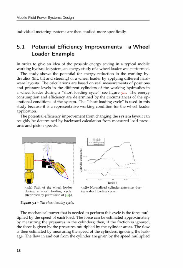
In order to give an idea of the possible energy saving in a typical mobileworking hydraulic system, an energy study of a wheel loader was performed.
The study shows the potential for energy reduction in the working hy-draulics (lift, tilt and steering) of a wheel loader by applying different hard-ware layouts. The calculations are based on real measurements of positionsand pressure levels in the different cylinders of the working hydraulics ina wheel loader during a “short loading cycle”, see figure 5.1. The energyconsumption and efficiency are determined by the circumstances of the op-erational conditions of the system. The “short loading cycle” is used in thisstudy because it is a representative working condition for the wheel loaderapplication.
The potential efficiency improvement from changing the system layout canroughly be determined by backward calculation from measured load press-ures and piston speeds.
5.1(a) Path of the wheel loaderduring a short loading cycle.(Reprinted by permission of [49].)
0 0.25 0.5 0.75 1
0.5
0.75
1
Lift cylinderTilt cylinderSteer cylinder 1Steer cylinder 2
Cyl
ind
erex
ten
sion
[-]
Time [-]
5.1(b) Normalized cylinder extension dur-ing a short loading cycle.
Figure 5.1 – The short loading cycle.
The mechanical power that is needed to perform this cycle is the force mul-tiplied by the speed of each load. The force can be estimated approximatelyby measuring the pressures in the cylinders; then, if the friction is ignored,the force is given by the pressures multiplied by the cylinder areas. The flowis then estimated by measuring the speed of the cylinders, ignoring the leak-age. The flow in and out from the cylinder are given by the speed multiplied
18

Energy Efficient Mobile Systems
by the cylinder areas. The power needed is then approximately the forcemultiplied by the speed of each cylinder.
In this particular study the working hydraulics are studied. This concernsthe boom cylinders, the tilt cylinder and the steering cylinders. The presentedfigures are thus not valid for a whole vehicle, only the working hydraulicssubsystem.
5.1.1 Calculation Cases
This section describes the different cases used when the energy consumptionof the short working cycle was calculated. All calculations in this sectionare only rough estimations, but they give a good overall picture of the dif-ference between the working hydraulics configurations in respect of energyconsumption.
Case 1
This case represents the minimum energy consumption that can be achieved.Only pure mechanical energy is considered.
This corresponds to a hydraulic system with an efficiency of 100%. Thereare no throttling losses in the system. It is possible to store energy over time.This system has to contain some kind of ideal accumulator.
Case 2
Here it is assumed that the system cannot assimilate energy over time. Thismeans, roughly, that the system does not contain any accumulators, but thatflow can be transferred between cylinders instantaneously. There are stillno throttling losses in the system. Otherwise, conditions are the same as inCase 1.
Case 3
This corresponds to the system of today. Here, the system pressure is as-sumed to be equal to the LS-pressure, which is the highest sensed load press-ure.
Case 4
The last case studied is when independent meter-in and meter-out orifices inthe valves are introduced. The LS-pressure is calculated similarly to Case 3.There are two main reasons why this system can save a considerable amountof energy using these kinds of valves. These are the opportunity to use:
19

Mobile Fluid Power Systems Design
Differential mode When dealing with small partial loads it is possible tominimize the pressure drop over a cylinder by connecting both cylinderchambers directly to the high pressure line. This is called differentialmode.
Floating mode When dealing with, for example, lowering loads it is possibleto minimize the pressure drop over a cylinder by using the floatingmode, which is when the cylinder chambers are directly connected tothe tank line.
5.1.2 Energy Efficiency Comparison of the Different Cases
Normalized1 results of the calculations described above are shown in table 5.1and figure 5.2. In table 5.1 the energy consumed is shown for the four differ-ent cases.
Table 5.1 – Calculated normalized energy consumption during the short loading cycle.
Case 1 Case 2 Case 3 Case 4
Lift 0.48 0.70 1.00 0.75Tilt 0.15 0.42 1.00 0.68
Steer 0.40 0.40 1.00 0.96Total 0.37 0.60 1.00 0.74
The calculations suggest that there exists good potential to reduce the en-ergy consumption of the working hydraulics in a modern wheel loader. Byintroducing the split spool concept, Case 4, there is an energy reduction ofabout 25%.
1The normalization is done because of secrecy reasons from the data provider.
20

Energy Efficient Mobile Systems
0 0.5 1−0.5
0
0.5
1
Pow
er[-
]
Time [-]5.2(a) Case 1.
0 0.5 1−0.5
0
0.5
1
TotaltLift functionTilt functionSteer function
Pow
er[-
]
Time [-]5.2(b) Case 2.
0 0.5 1−0.5
0
0.5
1
Pow
er[-
]
Time [-]5.2(c) Case 3.
0 0.5 1−0.5
0
0.5
1
Pow
er[-
]
Time [-]5.2(d) Case 4.
Figure 5.2 – Normalized power consumption during the short loading cycle in the dif-ferent cases.
21

Mobile Fluid Power Systems Design
5.2 Flow Controlled Systems
In load sensing (LS) systems the actuation of the different loads is carriedout by joystick signals. These signals pose either a flow or pressure demandfrom the operator. LS systems used in mobile applications are commonlyequipped with pressure compensators. They maintain a constant pressuredrop over the directional valves. This constant pressure drop makes the sig-nals from the operator correspond to flow demands. There are different waysof controlling the pump in this kind of system. The LS system approachshown in figure 5.3(a) uses a pressure controlled pump and flow controlledvalves.
Since the operator’s signals correspond to flow demands it seems morenatural to control the pump by flow. Traditional pre-compensated valvesare not feasible together with this kind of pump control because of theirreducing valve characteristics. One flow controlled pump control strategy isto control the pump displacement directly; both the pump and the valves arethen flow controlled. The pump flow is set to the sum of the flow demandsof the actuators, which are proportional to their velocity demands. However,if they are not perfectly matched problems will arise. Two situations mayoccur:
1. The pump flow is too high. Both compensator spools will close moreand the pump pressure will increase until the system relief valve opens.The throttle losses will be huge and the system will emerge as a con-stant pressure system.
2. The pump flow is too low. The lightest load will slow down and possi-bly even stop.
This means that the components must be highly accurate. The reason isthat traditional pre-compensators control the absolute pressure drop over thecontrol orifice by reducing the pump pressure relative to the load pressureof its own load. This works fine as long as the pump pressure is activelycontrolled, with for instance an LS feedback.
There are work-arounds to address this unsatisfactory property. The keyis to implicate the highest load pressure into the compensators to avoid thisbehaviour. This can be done by using compensators placed downstream ofthe control orifice, so called post-compensators. The compensators then actas relief valves instead of reducing valves and all the valve sections will workagainst the highest load pressure. The entire pump flow will thus be dis-tributed relative to the individual valve openings. This approach has beenstudied, for example, in [12] and [16].
It is possible to combine the properties of pre-compensators and post-compensators. One solution is to use the actual pressure difference betweenthe highest load pressure and the pump pressure to replace the fixed springpreload in figure 5.3(a). Such a system can be seen in figure 5.3(b).
22

Energy Efficient Mobile Systems
Contr.ql2
ql1
qp
pp
F0
F0
pl2
pl1
plMAX
5.3(a) Traditional load sensing (LS) system with pressure compensateddirectional valves.
ql2
ql1
qp
pp
Ac1
Ac2
pm1
pm2
pl2
pl1
plMAX
ε
5.3(b) Flow controlled system with flow-dividing pressure pre-compensators.
Figure 5.3 – Two different approaches to system design where the control valves arepressure compensated, both using pre-compensators.
23

Mobile Fluid Power Systems Design
More on flow controlled systems can be found in paper [IV].
5.2.1 Hardware
The hardware in this kind of system is similar to a traditional LS valve sys-tem. To achieve the same system capacity the same magnitude of pump sizeis used; only the pump controller needs to be different. Instead of activelycontrolling the pump pressure above a certain pressure margin with a highestload pressure hardware arrangement, the pump displacement is controlleddirectly from the operator demand signal. This yields a system where theload sensing hose to the pump controller can be removed and replaced withan electrically controlled displacement controller. Both systems can be seenin figure 5.3.
Pre-compensators have the advantages of simpler installation and thatmost existing systems already use pre-compensators. In some systems,pre-compensators can be more or less replaced with flow sharing pre-compensators without even replacing the valve housing.
The flow paths in this system are equal to the flow paths in a conventionalLS system, see figure 5.3. The difference in energy consumption is primar-ily a consequence of the possibility of reducing the pressure drop over thecompensators and the directional valve sections. The compensators can bedesigned in such a way that the pressure drop over it is minimized. This isdescribed in detail in [IV]. Also, the pressure margin pre-set by the pumpcontroller is eliminated. Instead of the prescribed pressure margin, the press-ure drop is given by the resistance in the hoses and the compensator restric-tion.
There is no need for sensors to achieve the desired functionality with thissolution. However, it could be beneficial to use sensors to, for example, de-termine when end stops are reached. It is then possible to adjust the pumpflow and avoid unnecessary energy losses.
5.2.2 A Demonstrator System
To verify the properties of flow controlled systems measurements were per-formed. The application was a wheel loader with an operational weight of6900 kg, figure 5.4. The machine was equipped with a pump that couldbe operated both in pressure and displacement control modes. The usedvalve was prepared for use with both types of compensator described in sec-tion 5.2.1. This simplified the tests since the same pump and directional valvecould be used in both test cases. A short working cycle was used for com-parison tests between conventional LS operation and flow control operationwhen the measurements were performed. It is the dynamic properties andthe reduction of energy consumption that are of interest to look at.
24

Energy Efficient Mobile Systems
Figure 5.4 – The machine used for experiments.
In figure 5.5(b) a reduction of the pressure drop between the pump outletand the highest load pressure can be seen. The actuator speed is similar inboth test runs, see figure 5.5(a). The energy consumption of the workinghydraulics was reduced by about 14% in this measurement. Keep in mindthat this is a figure specific to this particular application and operationalconditions. However, the result shows that there is a potential for energysavings in this kind of system. These measurements are described in moredetail in [XII].
0 1 2 3 4 5 60
50
100
150
Time [s]
Flo
w [l
/min
]
5.5(a) Measured flow for the sameload in tests both with load sens-ing (LS) system and flow-dividingpressure compensators.
0 1 2 3 4 5 60
5
10
15
20
25
30
35
40
45
50
Time [s]
Pre
ssur
e [b
ar]
LSFlow control
5.5(b) Measured pressure differencefrom the system pump and the direc-tional valve during the same runs pre-sented in figure 5.5(a).
Figure 5.5 – Experiment to verify the potential of reducing pressure drops over thecompensators in flow-dividing systems.
Also, the system with flow sharing pressure compensators and flow con-trolled pump is less oscillative. The controller in load sensing pumps oftenreduces the damping in systems. This has been studied in previous research,for example see [3].
25

Mobile Fluid Power Systems Design
5.3 Individual Metering Systems
Individual metering systems are a class of fluid power systems where themeter-in and meter-out control valves are individually controlled. This sec-tion gives an overview of how individual systems can be designed and theirproperties.
There is also an example of a specific system which was designed andtested. This system uses proportional poppet valves, which make use of theValvistor principle.
5.3.1 Hardware
The hardware in individual metering systems can be designed in variousways. Different kinds of valves and different layouts can be utilised. In thissection different hardware layouts, how different connection schemes resultin different feasibility for energy recovery and so on are presented.
The main characteristic features of independent metering systems are:
Metering losses reduction When controlling a meter-in orifice in a conven-tional system the meter-out orifice opening is determined by the spoolposition. For an individual metering system the meter-out orifice canbe independently controlled from the meter-in orifice with the objectiveof, for example, reducing metering losses.
Dynamic response improvements Individual metering systems have moreinput signals to the plant system compared to a conventional system,which means that a controller has superior opportunities for sophisti-cated control.
General hardware Unlike conventional valves where a valve can be specifiedin an enormous number of different spools or configurations, indepen-dent metering valves can be designed more generically. For example,software parameter changes can be made instead of different grindingsof spools. Product variety can be decreased by a change-over to inde-pendent metering valves. This gives the opportunity for an OEM tochoose among different component suppliers due to general hardwarewith no application-dependent notches and so on.
Productivity improvements With the same system power supply2, an indi-vidual metering system is able to increase the speed of a load undercertain conditions. For example, while lifting a light load the cylindercan be regeneratively controlled due to the independently controlledmeter-in and meter-out valves. A higher force can also be applied on theload due to lower pressure losses, for instance lower meter-out pressuredrops.
2In practice this means with the same pump size.
26

Energy Efficient Mobile Systems
Stability improvements Increased control possibilities open for more effi-cient damping measures to be implemented. For example, the cylinderchamber pressures can be individually controlled in an individual me-tering system.
Customisable system characteristics System characteristics such as spoolnotches no longer have to be established by hardware. In individualmetering systems it would even be possible to let the operator changethe system characteristics on-line.
Float functionality Desirable functionality like floating operation, for exam-ple a non-powered motion of a cylinder. This is a common function forthe bucket in wheel loader applications. Floating operation also savesenergy compared to forced motion since no pump flow is needed.
Recuperation/regeneration functionality Mobile systems operate in a widerange of operation. There is often also one single pump supplying anumber of different functions. These things together often cause mobilesystems to generate significant losses. These losses can be efficiently re-duced by using the cylinders at part load as discrete transformers. Thisis done by connecting both cylinder chambers to the pump line to trans-form the pressure up and transform the flow down. Then the press-ure demand at part load endeavours to approach the governing systempressure and the throttling losses can thereby be reduced. Individualmetering also enables recuperation of load energy, during lowering forinstance, to the pump line and other loads.
Given a specific design pattern there often exists a set of different subcat-egories. This is also true for individual metering systems. All systems infigure 5.6 are able to meet the requirements for enabling the features listedabove. The different layouts all have their pros and cons.
The concepts can also be combinations of each other. One example is avalve system presented by Andersson in [32].
There also exist solutions where additional valves are presented. For ex-ample, Book and Goering in [50] propose a valve connection between thepump and tank port. This valve is not necessary to fulfil the flexibility statedabove, but there may be other reasons to add a valve like this. One is tosubstitute basic features such as relief functionality. In [38] Hu and Zhangshow different implementations of conventional systems, for example open-center, closed-center, and “regeneration” functions with a five-valve solution.In [20] Liu and Yao present a system also using five metering elements; forexample they use the cross-load-port valve to obtain regeneration in situa-tions where the load is used as the power source for the motion. In [21]Kong et al. present an implementation of independent metering valves ina five-valve configuration to achieve matching of asymmetric loads. In [26]Nielsen gives an overview of different valve concepts, some of them using
27

Mobile Fluid Power Systems Design
5.6(a) 3/3-valves. 5.6(b) 3/3-valve and2/2-valve combination.
5.6(c) 2/2-valves. 5.6(d) Five 2/2-valves.
5.6(e) 3/3-valve. 5.6(f) 3/3-valve and2/2-valve combination.
Figure 5.6 – Different system layouts for independent metering systems.
extra valves. In [45, 46] Linjama et al. discuss dynamic benefits of using anextra valve that connects both load ports. Yao works with a poppet valvebased individual metering system utilizing five valves [51].
More on the configurations can be found in [I]. A broad overview of dif-ferent valve configurations and their characteristics is given by Backé in [52].
Valves
In a chosen system layout the choice of components, especially valves andtheir types, are nested and coupled with the chosen system layout itself. Thedifferent systems in figure 5.6 are best suited to different types of valves.Generally speaking, all valves can be realized as spool valves. In contrast to,for example, 3/3-valves, 2/2-valves can be realized as poppet valves as well.
Spool valves have a number of advantages. The technique with notchesfor small valve displacements enables accurate valve opening control.Yuan et al. [53] have for example worked with accurate flow control inspool valves for individual metering systems. Spool valves are easily madepressure balanced. The resulting force at the spool is less dependent on the
28

Energy Efficient Mobile Systems
pressure drop over the spool compared to the force at the poppet in pop-pet valves. This is why spool valves have been widely used as directionalproportional valves in motion control in both the mobile and industrial hy-draulic fields. Examples of works where spool valves have been studied ascomponents in individual metering systems are [42] by Yuan and Lew, [26]by Nielsen and [54] by Liu et al. Lin and Akers [55] analysed a servo valvewith decoupled spools and concluded that from a dynamic perspective thetwo-spool configuration is slower but manufacture can be made more cost-effective. Anderson and Li have also studied a two-spool valve type servovalve in [56] where a mathematical model is also presented.
Poppet valves also have a number of advantages. Poppet valves can bedesigned to have an extremely low leakage when closed. It is possible tointegrate other functions, for example chock releases, check valve behaviour,and so on in poppet valves. They also require less precise machining. Thedesign also makes them capable of adjusting themselves as they wear. Sincethe seat seals the valve, the poppet can be machined with lower diametricaltolerances. The valve can then also be made less sensitive to contamination.Examples of works where poppet valves are used as components in individ-ual metering systems are [39] by Pfaff, [23] and [II] by Eriksson and [57] byXu et al.
The low leakage makes poppet valves appropriate as meter-out elements.The check valve behaviour can be used to advantage in the system design,for example as anti-cavitation functionality. Generally, poppet valves have astrong pressure dependency. This makes them suitable for pressure control.However, if a position feedback from the poppet is introduced it allows forreduced pressure dependency. In the late ’70s and early ’80s several pro-portionally controlled poppet valve concepts were presented. There wereresearch activities on different kinds of feedback mechanisms, for exampleelectrical feedback by using position sensors, force feedback using springs,follow-up servo mechanisms, and also combinations of these. See section 5.4for more on different poppet valve concepts. A survey of poppet valve con-cepts can be found in Andersson [58] and Backé [59].
Andersson [58] also introduced a proportional controlled poppet valve con-cept called the Valvistor principle. This valve concept is nowadays marketedand sold by several companies. It is a poppet valve concept with hydraulicposition feedback, see section 5.4.1. The feedback mechanism is a slot in thecylindrical surface of the poppet. The pilot flow goes through this slot inseries to the pilot valve. When the valve opens up, and the poppet lifts, theslot opens up its flow area correspondingly. It is analogous to an electricalpotentiometer. The Valvistor valve as a whole can be compared to an electricbipolar transistor component. It amplifies flow, analogous to how a bipolartransistor amplifies current. The Valvistor concept has been studied in [V] asa component in independent metering systems.
Among the disadvantages of poppet valves are stability issues. The
29
Mobile Fluid Power Systems Design
topic of poppet valve stability has been studied by Funk [60], McCloy andMcGuigan [61], Shin [62], Hayashi [63], Muller and Fales [64] and Eriks-son et al. [VI] among others.
5.3.2 Control
In contrast to conventional mobile systems with 4/3-valves, individual me-tering systems have to include some kind of controller for the valves. Con-ventional systems have one input signal for each load, a spool position. Bymeans of this signal an operator is able to control one output signal in anopen loop manner, for example speed or force/torque. An individual me-tering system incorporates at least two input signals, a meter-in signal and ameter-out signal. To manage the manoeuvring of these systems, a controllerneeds to control at least all but one input signal. The last one can be con-trolled by an operator in an open loop manner. For example, the operatorcontrols the meter-in orifice directly and the controller controls the meter-outorifice, or the other way around. Of course, all valves can be controlled inclosed loops where the operator generates reference signals to closed loopcontrollers.
There are a number of parameters/variables to consider when designingan individual metering control system. These include:
Control output variables Different sets of state variables can be chosen ascontrol output. Load speed or actuator force are common output vari-ables. In individual metering systems it is possible to control more thanone output signal. For example, load speed and a pressure level in theactuator can be chosen as control signals. Another example of cho-sen output signals is [II] where valve positions are controlled to try toachieve an open position for energy saving purposes. Mode switchingcontrollers are also commonly used to increase the flexibility of inde-pendent metering systems. The set of output variables and/or inputsignals can then be allowed to change between different modes duringoperation. Since this kind of system is often considered for its energy-saving capability, energy or power itself could be an interesting controloutput variable.
Sensor signals (feedback signals) Computer based control systems needsensors to provide feedback signals. A failure, hydraulic or otherwise,can always occur. It is the question of probability and effect of a failurethat is interesting. Consequently, the number of sensors should bekept to a minimum and when a sensor breaks it should not cause ahazardous situation. There are both safety and production availabilityaspects of failures such as a sensor failure. It can also be critical if sen-sors are inaccurate, for example if a small pressure drop is measuredby two pressure sensors. The direction of a pressure drop can then be
30
Energy Efficient Mobile Systems
misjudged. Such errors can cause a load to drop into the ground forexample. It is important to be aware of the risks in complex systems;a tool to use in the design is for example fmea. Most independentmetering systems incorporate pressure sensors.
Control strategy for supply (pump) The pump/pumps in a system have tobe controlled somehow, as well as the valves. Variable pump systems oftoday, in particular LS-systems, control the pump hydro-mechanicallyand separate from the valve control. Independent metering systemsutilizing a complex control structure can however take advantage ofincorporating the pump control into the system control. This of courserequires an electrically controlled pump.
Various control approaches have been implemented and tested in differentresearch works. One approach is to manually decouple the output variablesthrough physical decoupling [35, 65–67]. There have also been efforts to useLQ-techniques [36] and [III]. In [III] the LQ-technique was used to design astate feedback. The strong coupling between the valve signals and the flowswere used to simplify the state estimations. Traditional PID-controllers havealso been investigated in independent metering systems [46].
A mobile fluid power system is considered to be a tough control appli-cation. This is due to all the non-linearities present in fluid power sys-tems. Common non-linearities include flow/pressure characteristics in ori-fices, valve hysteresis, dead-band and saturation. Fluid power systems alsofrequently change parameters during operation. In [68] Burrows emphasisesthe importance of development in the areas of robust control techniques ca-pable of dealing with model uncertainty and parameter variations. He alsomentions that non-model-based methods are also interesting for fluid powerapplications for the same reason.
There are different approaches to handle these issues. One is to designthe controller conservatively and assume a worst case operational point. An-other is to utilise an adaptive controller scheme to estimate varying systemparameters on-line. Stoten and Bulut [69] have implemented the adaptive al-gorithm MCS (“minimal control synthesis”) in an electro-hydraulic positionservo. Plummer and Vaughan [70] have implemented a pole placement con-trol method for an electro-hydraulic positioning system using an adaptiverecursive least square scheme to estimate system parameters. Yao [51, 71, 72]has worked on an implementation of the ARC (“adaptive robust control”)strategy for individual metering systems.
Overviews of the research in the area of control of hydraulic systems havebeen presented by Edge [73], Murrenhoff [74] and Burrows [68] among oth-ers.
How to implement the controllers in the sense of hardware and softwareis also of interest. A hardware and software architecture of a distributed em-bedded electro-hydraulic system in a telehandler is presented by Yuan et al.
31

Mobile Fluid Power Systems Design
in [75].
Mode Switching
A two-ported hydraulic load with connections to pump supply and tankneeds two orifices to be operated, one to control the fluid at each port. Inindividual metering systems with multiple choices of possible valves andflow paths for supply and drain of a load, a supervisor controller is needed.
In an early publication in this area Jansson and Palmberg [19] discuss dif-ferent modes of operation. Liu and Yao [20, 76] split up the control in to a“valve level” controller and a “task level” controller. The operation mode ischosen in the task level controller using the desired load speed and force to-gether with the actual load pressures. Often the reference from the operatoris one signal, for example the load speed, then the desired force needs to becalculated. Liu and Yao use an adaptive control scheme.
Pfaff [39] and Tabor [41, 77] both use a telehandler as the application. Inthat particular application three different modes of operation are used. Alsohere, the controller task is split up into a “valve controller” and a “modeselector”. It is stated that the mode selector switches mode on the basis ofpressure sensors and joystick signals.
In [78] Shenouda and Book show how to find an optimal switching pointfor a four-valve configuration. They show that the optimal switching pointfor their application is the intersection of the capability curves, which is thecrossover point of the “normal operation” and “regenerative operation” in aforce-speed diagram.
The different modes can be classified in several ways. For example, thiswork has a different classification of modes compared to Pfaff [39] and Ta-bor [41, 77], see section 5.3.3, [23] and [II]. However, there are a number ofoperational conditions which recur. One example is when the meter-in loadport is connected to pump and the meter-out port is connected to tank, of-ten referred to as “normal mode”. Another is when both mentioned portsare connected to pump, “high-side regeneration”. For the same load, theabsolute pressure levels in the chambers are divergent from each other de-pending on how the ports are connected. The pressure difference for themeter-in chamber in a cylinder between these two modes for the same loadis:
pregen
pnormal=
11 − κ
(5.1)
where κ is the area ratio of the cylinder, pregen is the cylinder pressure inregenerative mode, and pnormal is the cylinder pressure in the piston cham-ber in normal mode. The pressure in the piston rod chamber is assumedto be tank pressure in “normal mode”. As an example, if the area ratio is0.5 the pressure difference of the piston chamber is about 50%. Similarly,
32
Energy Efficient Mobile Systems
there will be pressure differences at the meter-out chamber. A challenge is toavoid pressure peaks and achieve a smooth transition between such meteringmodes.
Shenouda [40] uses an analogy to automatic transmission gear shifting. Hehas also done research on a continuous mode switching as a measure forsmoother transients during mode switches. This continuous mode switchoperation involves operation by three valves simultaneously.
This work proposes a strategy of avoiding the pressure transients by meet-ing the “high-side regeneration” from “normal mode” through the meter-outorifice increasing the pressure in the meter-out chamber, see section 5.3.3,[II] and [23]. Further, there is a check valve connection from the pump tothe cylinder rod chamber, which means that when the pressure reaches thepump pressure, flow will go back to the pump and the mode has switchedwith no significant pressure peaks.
Dynamic Considerations
System dynamics are often crucial in fluid power system design. Even in sys-tems with open loop control dynamic issues can be present, due for exampleto volumes, flow-pressure characteristics and masses, see Merritt [79].
Modern individual metering systems often contain sensors that feed backsignals to the valves via complex controllers. The dynamic system character-istics then become an issue for stability and not only for performance whichis the case with open loop controlled systems. In modern electro-hydraulicsystems there are extensive possibilities for sophisticated manipulation offeedback signals by computer controllers. This enables the controller to in-troduce stabilising measures, e.g. dynamic pressure feedbacks.
Typical of individual metering systems is that both flow and pressure con-trol are present simultaneously in closed loops, for instance in cylinder drivesthere may be pressure control at meter-out chambers and flow control atmeter-in chambers. In some cases the circumstances may resemble the over-centre valve configuration, for example when the pressure at one of the loadports is controlled by the flow at the other load port. Over-centre valves havebeen studied by Persson [80], Andersen et al. [81] and Pedersen et al. [82]among others.
5.3.3 A Demonstrator System
This work introduces a novel system design utilizing independent meter-inand meter-out valves that increase energy efficiency in a system that consistsof a pump connected to more than one hydraulic actuator, see [II] and [23].Patents for this particular system have been applied for, see appendix A.
In other proposed solutions, pressure sensors play a key role as regardscontrollability, see chapter 2. Here, another solution is proposed that is not
33

Mobile Fluid Power Systems Design
dependent on pressure sensors for either flow control or mode selection. Themain difference between the work presented in this work and the work doneby others mentioned above is the control strategy. The choice of output sig-nals in the closed loops is new. Some functionality is kept in hardware toavoid critical sensor dependencies.
The presented system uses pressure compensators to achieve desired flows.The controller is fed with a speed reference signal by the operator for eachload. It then decides which valves to use and controls them in an openloop manner in respect of the flows. When deciding which valves to usethe controller will try to minimize the total throttle losses in the system. Ifpossible, the load will recuperate high pressure oil back to the pump, whichthen can be operated as a motor.
The system will automatically choose from the following operating cases:
Recuperative operation In the case of a lowering load, for example, the oilinto the cylinder is withdrawn from the tank. The load will then itselfpressurize the oil in the opposite cylinder chamber and pump it intothe pump line of the system. The cylinder thus works as a pump andcan be used to drive other loads or operate the system pump as a motor.
Energy neutral operation When the load is not large enough to pressurizethe oil above the pump pressure, the system will instead leave it forthe tank. As in the “recuperation mode”, the oil into the load is with-drawn from the tank. No power is taken from the system pump. Thisoperating case is also referred to as “floating mode”.
Regenerative operation The oil into the load is withdrawn from the pump.If the pressure in the other load port exeeds the pump pressure, thereturning oil from the load is fed back to the pump line. If the load isa cylinder load, the cylinder will act as a transformer in this operatingmode.
Normal mode The highest load in the system will be operated as in a con-ventional system. The oil is withdrawn from the pump and the returnoil is fed to the tank.
System Description
This section describes the novel proposed system. Both the hardware and thecontrol laws are shown. Pressure compensated proportionally controlled 2/2poppet valves of a modified Valvistor type are used, see section 5.4 and also[V], [23] and [58]. The sensors that are used in the control loop are positionsensors that measure the position of the compensator spools. No pressuresensors are needed.
The system is designed to meet the flexibility requirements for utilizingenergy efficient operation, for example power recuperation and regenerativedrive. The different operation cases are shown in figure 5.7 below.
34

Energy Efficient Mobile Systems
Figure 5.7 – Definition of the different operation cases.
The system has to be able to connect pump or tank to each cylinder cham-ber independently of each other. The possible configurations are more indetail described in section 5.3.1 and [I].
Systems that utilize independently controlled meter-in and meter-outvalves often have most of their functionality, such as pressure compensa-tion, moved into software. In such hardware configurations, the sensorsare essential to enable functionality as flow control. See for example [53]and [33].
In this system the ideas are different. The most important functionality iskept in hardware. Pressure compensation, for instance, is kept in the hard-ware in this system, see figure 5.8. The position of the pressure compensatorspools is measured and used both for mode selection and to control feedbacksignals. The control loops are discussed later. Details of the bi-directionalpressure compensated valves can be found in [V].
Control
There are two control aims in this novel system:
1. Follow the reference speed given by the operator.
2. Use as little energy as possible from the pump to utilize the desiredmotion specified by the operator.
The controller is split into two different parts:
1. The operator who controls the speed of the cylinder. The speed controlloop is of an open loop control type; the operator himself closes theloop. Because of the pressure compensation of the valves there is no orweak load dependence and cross-talk3 between the loads.
3Cross-talk in this sense means when changes in one load influences other loads in terms ofspeed.
35

Mobile Fluid Power Systems Design
5.8(a) Hardware layout, see [V, VI] for details ofthe valves. However, observe that the orientationof the Valvistors should be considered due to thepreferred leakage characteristics since the Valvsi-tor is almost leakage-free in one flow direction.
5.8(b) Hardware describedschematically. Note that thedouble pilot circuits make thevalve bi-directional.
Figure 5.8 – Description of the hardware used in the system.
2. Choice of which valves to use to achieve the energy saving ability.
There are up to four different choices of which valves to use depending onthe load. These choices are listed below and are intuitively ranked from anefficiency point of view, starting with the most suitable:
1. Recuperative operation; energy is gathered from the load and can beused at other actuators in the system or to operate the pump as a motor.
2. Energy neutral operation; no energy is needed to perform the operation.
3. Regenerative operation; a good option if the pump pressure is high atthe moment (another load has a higher pressure demand) so that lessflow is then used from the pump.
4. Normal mode (The conventional way); has to be used at the load withthe highest pressure demand. By using independent meter-in andmeter-out valves the meter-out pressure drop can be smaller than usual.In this work meter-out always denotes where flow leaves the cylinderand meter-in always relates to flow entering the cylinder.
The condition that has to be fulfilled to be able to operate in the recuper-ation operation case is that the load is large enough to build up a higherpressure in the cylinder chamber than the pump pressure, and of course theload has to act in the desired motion direction. Since pressure compensatorsare used for flow control the position of the spools in the compensators pro-
36
Energy Efficient Mobile Systems
vides information4 about whether a valve is capable of delivering flow in acertain flow direction or not.
If the condition to operate in the recuperation operation case is not fulfilled,the system will try to operate in the energy neutral operation case. Thisoperation case can be analogously described as the recuperation operationcase; the difference is that the oil is delivered to the tank instead of the pump.
These two operation cases, recuperation and energy neutral operation, arehere called meter-out control mode since the speed (or flow) control is ef-fected at a meter-out valve. This is visualised in the left part of figure 5.7.
When neither of these operation cases can be used, the system will startusing oil from the pump. The speed control is now effected at the meter-invalve, see the right part of figure 5.7. As mentioned previously, the regener-ative operation case is preferred to the conventional operation case, at leastwhen the present load is not the heaviest one. This can be realized by con-trolling the position of the compensator spool of the meter-in valve with themeter-out valves. If the compensator at the meter-in valve is controlled to beheld in a relatively open position, this is the same thing as saying that thepressure drop over the same valve is controlled to be held low. The pressurelevel in the cylinder chambers is then as high as possible for the given pumppressure. If the load is small enough the pressure in the meter-out chamberof the cylinder is higher then the pump pressure and the regenerative oper-ation is automatically enabled; otherwise the meter-out valve to tank has tobe used.
Both meter-out valves, the one from the meter-out cylinder chamber to tankas well as the one connected from the meter-out cylinder chamber to pump,are used to control the position of the compensator at the meter-in valve in aclosed loop manner.
By considering the choice of reference positions of the control loops of thecompensator positions the regeneration operation case can be prioritized overthe conventional operation case. This is explained in more detail in paper [II].
The idea of this system’s control system can be represented by a state ma-chine describing how modes are selected. See figure 5.9.
The structures of the control loops are shown in figure 5.10. The modeselector chooses which valves are to be active according to figure 5.9. Thedifferent control algorithms are activated as shown in the software box infigure 5.10. The closed loops in the software block are the control of thecompensator positions that are fed into the software from the compensatorsin the hardware. The joystick signal controls one of the valves as describedabove in an open loop manner.
So far, pump control has not been discussed. It is desirable that the pumpshould be controlled only by the load with the highest pressure demand.Analogous with the meter-in control mode, the pump controller is set to
4The position of the compensator spool gives information about the direction of the pressuredrop.
37
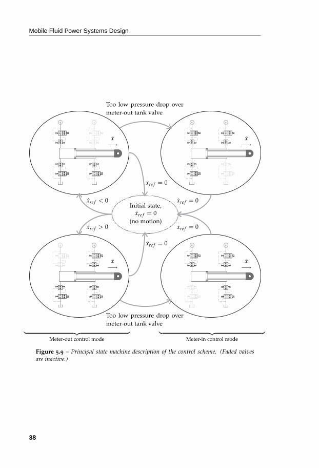
Mobile Fluid Power Systems Design
Initial state,xre f = 0
(no motion)xre f > 0
xre f < 0
xre f = 0
xre f = 0
xre f = 0
xre f = 0
Too low pressure drop overmeter-out tank valve
Too low pressure drop overmeter-out tank valve
x−→
x−→
x−→
x−→
︸ ︷︷ ︸
Meter-out control mode︸ ︷︷ ︸
Meter-in control mode
Figure 5.9 – Principal state machine description of the control scheme. (Faded valvesare inactive.)
38

Energy Efficient Mobile Systems
∆pre f
∆pre f
∆pre f
∆pre fProp.valve
Prop.valve
Prop.valve
Prop.valve
qA
qB
Modeselector
Inputfromoperator
Open andclosed loop control
Compensators,closed loop flow control
︸ ︷︷ ︸
Software︸ ︷︷ ︸
Hardware
Figure 5.10 – This is an overview of the control loops in the system. The electricalfeedback signals are the position of the compensator spools, which are the signals from thehardware back into the software block in the figure. The inner flow control loop is kept inthe hardware by the compensators. The software is split into two parts; it chooses whichmetering valve to use and also controls the meter-out valves in the meter-in mode in aclosed loop manner. The signal from the operator controls the flow magnitude in an openloop manner; the loop is of course closed by the operator. qA and qB are the flows to therespective cylinder ports. ∆pre f is a constant and is related to the pre-load of the springin the compensators.
control the compensator position of the meter-in valve. To get the right pri-oritization, the reference value is set so that the pump “kicks in” after themeter-out is fully open. To get better response it is also desirable to feed theflow needs forward to the pump controller. The flow needs can be estimatedfrom the joystick signals and the system controller.
Measurements
A proof of concept has been carried out. The control strategy described inthe previous sections has been implemented in a real-world application, aforwarder machine. Fast spool valves were used to emulate the valves in afinal system.
One of the functions in the forwarder is replaced with individual meter-ing valves. Both the demonstrator and the valve configuration are shown infigure 5.11. The jib function is chosen in this case. Six proportional valves
39

Mobile Fluid Power Systems Design
with additional pressure compensators were used to enable the functionaldemands of the system. lvdt sensors were used to determine the positionsof the compensator spools.
5.11(a) The demonstrator. 5.11(b) System layout.
Figure 5.11 – The demonstrator and the system layout used for the initial test of thesystem schematically described.
In order to test the valve system ability, the jib function was selected whenit runs over centre. This allows the valves to use most of the possible modesshown in figure 5.7. However, the modes where the flow demand from tankexceeds the return flow to tank were disabled due to the lack of pressurizedoil in the return line. The pump in the tested system was a conventionalpump and could thus not be used as a motor. This restricted the modeswhere oil is fed back to pump. In the test the pump was set constant toemulate pressure requirements set by other, heavier, loads at other functions.The pressure level was set to enable interesting switching between differentmodes.
The signals displayed in the graph, figure 5.12, are the valve displacementsignal, the pump flow, the absolute value of the flow in/out of piston cham-ber A, and the angle of the jib arm. The first part of the graph illustrates jibout motion5. The motion starts in energy neutral operation, since the press-ure drop from chamber A to tank is higher than a predefined level6. Whenthe pressure drop is too low, indicated by the compensator, pump flow isadded to chamber B and the system passes into normal operation. Observethat the initial part of the motion does not consume any pressurized oil fromthe pump.
The second part of the graph, figure 5.12, illustrates jib in motion7. Themotion starts in regenerative operation, since the pump pressure8 is high
5Equivalent to cylinder retraction.6This level corresponds to a compensator position on the AT valve.7Equivalent to cylinder extension.8The pump pressure level is decided by another, heavier, fictive load.
40

Energy Efficient Mobile Systems
0 10 20 30 401.5
5
10
UPAUATUPBUBPUBT
Time [s]
Vol
tage
[V]
5.12(a) Command signals to the valves.
0 10 20 30 400
10
20
30
40
QPQA
Time [s]
Flow
[l/
min
]
5.12(b) Measured flows.
0 10 20 30 400
45
90
135
180
Time [s]
An
gle
(deg
.)[-
]
5.12(c) Angular position during the cy-cle.
︸ ︷︷ ︸
Jib out︸ ︷︷ ︸
Jib in
Figure 5.12 – Measurement results from the demonstrator. The jib cylinder extendsbetween 0 and 15 s, then the cylinder is stopped and retracts between 20 s and 35 s.
enough to use the cylinder as a discrete transformer. When the pressure dropover the meter-in valve becomes too low, indicated by the compensator spoolposition, the operation is changed continuously from regenerative to normal.Observe that the regenerative part9 of the motion consumes only about onethird as much pressurized oil from the pump as in normal operation.
9From 30 s to 32 s in figure 5.12(b).
41

Mobile Fluid Power Systems Design
5.4 Poppet Valves
Energy efficient systems, such as those described earlier in this chapter, needa larger number of valves than conventional systems. On the other hand,simpler valves can be used. 2/2 proportionally controlled valves meet therequirements of this system.
The most common proportional valves are spool valves. Spool valves aresuitable for traditional systems because of the simplicity of control comparedto poppet valves. More than one orifice is, by the mechanical connection,often controlled by only one actuator. In this new kind of system the differentorifices are individually controlled. Therefore, the mechanical connection inspool valves at the orifices can not be utilized as an advantage.
Poppet valves are a suitable choice fore individual metering systems sincetheir design is often simpler then a spool valve design and is of the 2/2 type.They also often preferably have sealing properties. Unfortunately, they arealso often of the on/off type. However, there are a number of designs thatallow proportional control. Some examples are shown in figure 5.13 and arebriefly described below.
Electric feedback servo This principle uses an electrical signal from a po-sition sensor as feedback. The properties of such a design are mainlydetermined by the electrohydraulic actuator, statically and dynamically.It is a flexible configuration. A drawback is that it is totally dependenton electronics. See figure 5.13(a).
Force feedback servo The position control loop in this design is closed bythe spring arrangement between the pilot valve and the main poppet it-self. When the main poppet lifts, the pre-load of the spring between thepoppet and the pilot is increased. Depending on the applied externalforce, Finput, the steady state occurs at different main poppet openings.The input force is often realized by a current-controlled solenoid. Seefigure 5.13(b).
Mechanical feedback servo (Follow-up servo) In this design the pilot ori-fice is located directly in the main poppet. A rod then controls theopening degree of the pilot orifice; it is a needle orifice. Moving theneedle causes the pilot orifice to open. The pressure then decreases inthe control chamber above the poppet and the poppet lifts and closesthe needle orifice. The main poppet then follows the pilot rod. Theposition of the rod can for example be achieved by using a step motor,a solenoid, a hydraulic pilot arrangement, etc. See figure 5.13(c).
Combined force feedback and follow-up servo There are solutions that uti-lize both the follow-up and the force feedback mechanisms, for exampleto increase the stiffness in the position control loop of the main poppet.
42

Energy Efficient Mobile Systems
yre f
y
phigh
plow
5.13(a) Electrical signal feed-back.
Finput
phigh
plow
5.13(b) Mechanical forcefeedback (follow-up).
yre f
phigh
plow
5.13(c) Mechanical positionfeedback.
iinput
phigh
plow
5.13(d) Hydraulic positionfeedback (Valvistor).
Figure 5.13 – Different designs of proportionally controlled poppet valves. plow is thelow pressure side, e.g. tank/load port, phigh is the high pressure side, e.g. load/pumpport. yre f is the desired poppet position and Finput is a pilot force.
43

Mobile Fluid Power Systems Design
Hydraulic position feedback (Valvistor principle) The valvistor principleutilizes the position of the main poppet to control an orifice. By forceequilibrium of the main poppet, the opening of the orifice mimics thepilot valve opening. The result of the mimicking behavior is that theflow through the main poppet is an amplification of the pilot flow. Seefigure 5.13(d).
In this work the Valvistor concept has been studied and used as the valve ele-ment in the individual metering system in section 5.3.3. The main reason forusing this valve is its ability to keep functionality in small valves in the pilotcircuits. Another reason is that it is relatively simple to make bi-directional,see section 5.4.1.
5.4.1 The Valvistor Valve Principle
The Valvistor valve was originally developed at Linköping University in theearly 1980s by Andersson, see [58]. The Valvistor principle was first producedby Hydrauto, a Swedish valve manufacturer. Other research on the Valvistorvalve has been conducted after Andersson, e.g. by Pettersson, who devel-oped the “twin Valvistor” which is a design that increases the Valvistor’sbandwidth by putting a Valvistor valve in the pilot of another Valvistor [83]in [84]. There have also been interest in the valve principle from differentcompanies over the years.
Working Principle
The Valvistor principle is a proportional control principle for poppet valves.Characteristic of the Valvistor principle is the variable orifice that connectsone port to the control chamber above the poppet, see figure 5.14. This orificeis often a rectangular slot; the opening area of the slot is then proportional tothe opening stroke of the poppet itself. Figure 5.14 shows a Valvistor in thestandard design. The slot closes a hydraulic control loop for the position ofthe main poppet. The force equilibrium yields the pressure in the chamberabove the poppet. The slot orifice then assumes the position that correspondsto the opening area so that the right pressure drop is met.
The pilot flow drains the control chamber of oil at the same time as theslot orifice delivers oil into it. To fulfil the force equilibrium the pilot valveopening and the slot orifice opening are equal, assuming that the same flowregime is present at the different orifices. This means that the opening ofthe slot orifice mimics the pilot valve opening. The main poppet positionis controlled by the opening of the pilot valve. The valve acts as a flowamplifier, similar to the transistor component in the electrical world. Theideal flow gain is described by equation (5.2)
gideal = 1 +wmws√
1 − κ(5.2)
44

Energy Efficient Mobile Systems
A
B
5.14(a) B-type, flow direction from B toA.
A
B
5.14(b) A-type, flow direction from Ato B.
Figure 5.14 – The Valvistor valve.
were wm is the area gradient of the main orifice10 and ws is the area gradient11
of the slot in the main poppet. κ is the area ratio of the inlet area of the poppetand the control chamber area, Am, of the poppet. A determining factor thatdisturbs the ideal flow gain is the underlap in the slot. The underlap in theslot means that the slot is already slightly open when the main poppet isin its closed position. This underlap is necessary for stability reasons, seepaper [VI]. It adds a negative contribution to the ideal gain in equation (5.2)that is dependent on the main poppet position. However, there are waysto deal with this phenomenon. For example, the slot can be designed in anon-rectangular shape that compensates the non-linear relationship due tothe underlap. It is also possible to add a non-compensated flow through thepilot valve that cancels out the flow through the under lap during operationof the valve. This non-linear characteristics due to the underlap is studied inpaper [VI].
Since the main poppet mimics the pilot valve a pressure compensated pilotvalve results in a pressure compensated main stage. In such a design care tothe non-linear characteristics discussed above need to be taken into consid-eration. This valve is able to handle substantial flows due to the size of theactuated pilot valve. In some commercial valves, flow forces are utilized atthe pilot valve to make it pressure compensated.
The description of the Valvistor principle so far is true only for one flowdirection. In the opposite flow direction the valve acts as a check valve. Thisfeature can be utilized as an anti-cavitation function for example. In the
10If no soft opening arrangements are present at the poppet, the area gradient will be equal tothe diameter.
11If the slot is rectangular, the area gradient is equal to the width of the slot.
45
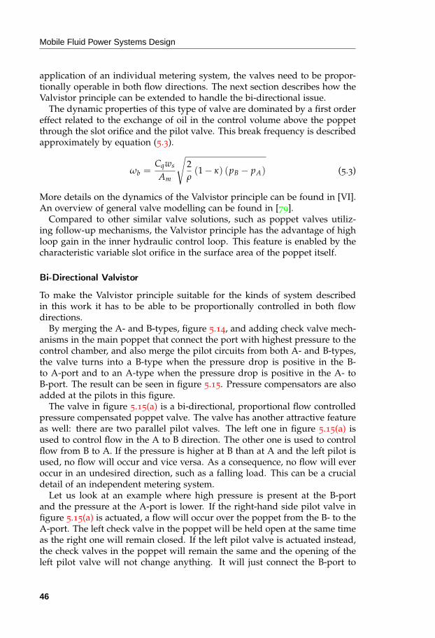
Mobile Fluid Power Systems Design
application of an individual metering system, the valves need to be propor-tionally operable in both flow directions. The next section describes how theValvistor principle can be extended to handle the bi-directional issue.
The dynamic properties of this type of valve are dominated by a first ordereffect related to the exchange of oil in the control volume above the poppetthrough the slot orifice and the pilot valve. This break frequency is describedapproximately by equation (5.3).
ωb =Cqws
Am
√
2ρ
(1 − κ) (pB − pA) (5.3)
More details on the dynamics of the Valvistor principle can be found in [VI].An overview of general valve modelling can be found in [79].
Compared to other similar valve solutions, such as poppet valves utiliz-ing follow-up mechanisms, the Valvistor principle has the advantage of highloop gain in the inner hydraulic control loop. This feature is enabled by thecharacteristic variable slot orifice in the surface area of the poppet itself.
Bi-Directional Valvistor
To make the Valvistor principle suitable for the kinds of system describedin this work it has to be able to be proportionally controlled in both flowdirections.
By merging the A- and B-types, figure 5.14, and adding check valve mech-anisms in the main poppet that connect the port with highest pressure to thecontrol chamber, and also merge the pilot circuits from both A- and B-types,the valve turns into a B-type when the pressure drop is positive in the B-to A-port and to an A-type when the pressure drop is positive in the A- toB-port. The result can be seen in figure 5.15. Pressure compensators are alsoadded at the pilots in this figure.
The valve in figure 5.15(a) is a bi-directional, proportional flow controlledpressure compensated poppet valve. The valve has another attractive featureas well: there are two parallel pilot valves. The left one in figure 5.15(a) isused to control flow in the A to B direction. The other one is used to controlflow from B to A. If the pressure is higher at B than at A and the left pilot isused, no flow will occur and vice versa. As a consequence, no flow will everoccur in an undesired direction, such as a falling load. This can be a crucialdetail of an independent metering system.
Let us look at an example where high pressure is present at the B-portand the pressure at the A-port is lower. If the right-hand side pilot valve infigure 5.15(a) is actuated, a flow will occur over the poppet from the B- to theA-port. The left check valve in the poppet will be held open at the same timeas the right one will remain closed. If the left pilot valve is actuated instead,the check valves in the poppet will remain the same and the opening of theleft pilot valve will not change anything. It will just connect the B-port to
46

Energy Efficient Mobile Systems
A
B
5.15(a) The bi-dirctional Valvistor valve.
A
B
5.15(b) Schematic view.
Figure 5.15 – The modified Valvistor valve.
47
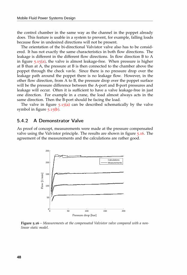
Mobile Fluid Power Systems Design
the control chamber in the same way as the channel in the poppet alreadydoes. This feature is usable in a system to prevent, for example, falling loadsbecause flow in undesired directions will not be present.
The orientation of the bi-directional Valvistor valve also has to be consid-ered. It has not exactly the same characteristics in both flow directions. Theleakage is different in the different flow directions. In flow direction B to Ain figure 5.15(a), the valve is almost leakage-free. When pressure is higherat B than at A, the pressure at B is then connected to the chamber above thepoppet through the check vavle. Since there is no pressure drop over theleakage path around the poppet there is no leakage flow. However, in theother flow direction, from A to B, the pressure drop over the poppet surfacewill be the pressure difference between the A-port and B-port pressures andleakage will occur. Often it is sufficient to have a valve leakage-free in justone direction. For example in a crane, the load almost always acts in thesame direction. Then the B-port should be facing the load.
The valve in figure 5.15(a) can be described schematically by the valvesymbol in figure 5.15(b).
5.4.2 A Demonstrator Valve
As proof of concept, measurements were made at the pressure compensatedvalve using the Valvistor principle. The results are shown in figure 5.16. Theagreement of the measurements and the calculations are rather good.
0 50 100 150 2000
50
100
150
200
250
CalculationsMeasurements
Pressure drop [bar]
Flow
[l/
min
]
Figure 5.16 – Measurements at the compensated Valvistor valve compared with a non-linear static model.
48

6
Simulation Tools
Simulation is an important tool that is used in the work of discov-ering and exploring new ideas and concepts. In this work, primarilyMatlab/SimulinkTM and AMESimTM have been used. To some extent thesimulation package Hopsan has also been used. This part of the work is tosome extent parallel to the work described in the previous chapters. The partof this work which is described in this chapter concerns a simulation tool it-self. This is motivated because the need for a proper simulation tool becomesobvious when working on fluid power systems such as those described inchapter 5.
6.1 Hopsan
The Hopsan simulation package, used primarily for hydro-mechanicalsimulation, has a long history and was first released in 1977.
From the beginning, Hopsan used a central solver, as most other simula-tion tools did, and still does. The Hopsan versions with a central solver wereinspired by the csmp/360 software from IBM. In the early ’90s, transmissionline modelling, TLM, was adopted. TLM, or bilateral delay line modellingas it was originally referred to as, can be traced back to the sixties, whereit was used for simulation of distributed systems, [85]. This method meansthat solvers can be distributed1 and also come with some other benefits, forexample improved scalability2 and higher numerical robustness, see for ex-ample [86] and [87]. One consequence of the distributed nature of TLM is
1This means that individual component models are isolated from each other so that theirequations can be solved independently.
2With TLM, the computational cost scales linearly to the size of the problem.
49

Mobile Fluid Power Systems Design
that the equations are not flattened, as is the case in for instance the Modelicalanguage. The initial TLM implementation was influenced by Hytran, [88].
Hopsan has been successful ever since it was first released in 1977. It hasmainly served as a research tool at the division of Fluid and Mechatronic Sys-tems, but has also been used by a number of companies for high performancesimulations.
Hopsan’s source code is rather complex and old-fashioned. The non-GUIcode, the core, is written in Fortran and C while the GUI code is writtenin Visual Basic and has been characterized by organic growth over severaldecades. The ageing code makes it difficult to maintain. It is also an obstacleto further development. Because of the need for improvements, work hasbegun on a new version of Hopsan. This work has been a part of that. Atthe time of writing, the new version, Hopsan NG is almost ready for users.Hopsan NG is still based on TLM and retains all of the benefits that comewith this method.
The largest difference compared to the current version of Hopsan is thatall component models are now written in C++ and are pre-compiled beforebeing added to a simulation system model. In earlier versions, models werewritten in Fortran and converted to C before compilation at every simula-tion run. The GUI application itself is more coherent and contains all Hopsantools within one application.
6.1.1 C++ and the Qt Framework
In an attempt to avoid the complexity and limitations of the old Hopsancode-base, development of the new version primarily uses open-source toolsand only cross-platform supported languages. The new Hopsan packageis still divided into a core and a GUI. The core is written in standard C++and the use of external third party dependencies is avoided. The GUI is alsowritten in C++, but uses the Qt cross-platform application and UI framework,see [89]. The Qt framework, released under the lgpl license, is easy to use,well documented, and offers plenty of features useful for GUI creation.
6.1.2 Hopsan Core
The Hopsan Core is an object-oriented C++ library containing the basic Hop-san classes and functions and a set of basic component libraries. It also in-cludes utility function libraries that can be of use when users are writing theirown components. A main program, for instance Hopsan GUI or some otherapplication, loads the library and instantiates an API class through which allcore communication is handled. The object-oriented approach gives a natu-ral containment of equations and variables into independent objects for eachimplemented component model.
50

Simulation Tools
As the core is a library, it can be used in any “main program”. This meansthat it is possible to run simulation models created in the GUI using only thecore and a small dedicated application. This may be useful for simulationin embedded systems where a graphical environment may not be present. Italso means that the core can be included in other applications to simulateHopsan models.
User Defined Components
The Hopsan Core comes with a basic component library useful for buildingsystems. For special applications and simulation of non-standard compo-nents, the user must be able to create additional components. In Hopsan NG,external components are shared libraries which can be dynamically linked inat runtime. Components must be written in C++ and are compiled separately.This means that the models can be distributed as black box models. In thecase of a company they can distribute simulation models for their productsto customers without revealing the underlying mathematical description (ormaybe controller code and similar). In the current development version, newcomponents are created by following a rather simplistic template. The useronly needs to specify a few things:
1. The type of component, whether to inherit the C, Q or S componentclass3.
2. A unique component type name, for instance “MySpecialOrifice”.
3. Local variables and which of them should be registered as componentparameters.
4. The kind of ports that should be available and what type of nodes theyrequire.
5. What the component must do at the initial time-step to properly initial-ize the connected nodes.
6. The equations for simulating one time step.
7. A line of code that registers the component with the global componentclass factory in the core.
As component creation follows a simple template, it is possible to write anautomatic component generator to assist the user in the modelling process. Acomponent generator for transforming a sub-set of Modelica code via Mathe-matica into Hopsan components exists, [90]. Based on this a MathematicaTM
to Hopsan NG component generator is already under development.
3The C, Q or S types are related to TLM, see paper [VII].
51

Mobile Fluid Power Systems Design
6.1.3 Hopsan GUI
Figure 6.1 – A screen-shot from Hopsan NG simulating a typical fluid power system.Component libraries are visible to the left and the main workspace and message windowto the right.
The Hopsan GUI is based on the Qt cross-platform application and UIframework. The cross-platform support in Qt means that the drawback withthe current Hopsan version, which is only available for Windows, is avoided.The GUI basically consists of graphical representations of the most importantcore objects, components, and system components. These can be moved bydragging-and-dropping and connected to each other with lines. A screen-shot of an example model and the Hopsan GUI interface is shown in fig-ure 6.1. The user interface and the possible actions are similar to those in thecurrent version. The look and feel of the GUI application are also similar tothose of many other modern graphical simulation tools.
The graphical appearance of the modelled components are loaded fromexternal plain text files and scalable vector graphics (SVG). The actual modelcode, however, is handled by the Hopsan Core library.
52

Simulation Tools
6.1.4 Scripting and Optimization
An important feature in a simulation program like Hopsan NG is the abilityto optimize parameters. For this the Python4 language is used. Hopsan NGinteracts with Python via a console integrated in the Hopsan GUI. This en-ables the user to script his/her models freely. For example, the users canuse their own or third party modules for optimization. This is where thescalability and numerical stability of TLM comes into its own.
References to work on optimization where Hopsan simulation models wereincluded in the optimization loop can be found from as long ago as the ’90s,for example [91].
4Python is a high level programming language. There are also free mathematical packagesavailable that have similar functionality to Matlab.
53


7
Discussion and
Conclusions
Eenergy efficiency in mobile fluid power working hydraulic systems canbe improved. There are a number of measures which can be applied to reducelosses in these kinds of system. This work studies flow controlled systemsand independent metering systems. They are compared with conventionalload sensing (LS) systems which are state-of-the-art in industry today.
Displacement controlled systems are not included in this work. However,some remarks regarding their comparison to individual metering systems arenecessary nonetheless. Often, when comparing displacement controlled sys-tems with various valve controlled systems one thing is rarely mentioned: thecost. There is a need for several pumps/motors instead of one. Since the loadfunctions have their own dedicated pump/motor, each has to be sized formaximum flow. A typical example of a dimensioning motion is the speed ofthe lowering bucket motion on a wheel loader. In the wheel loader example,the lowering flow from the boom cylinder can be several times the maximumpump flow in a similar valve controlled system. The difference is that forthe pump controlled system, all flow has to be handled by the pump/motor.Proportional valves can be a part of a solution by bypassing the pump/motora share of the lowering flow. Note that it has then become a hybrid of a dis-placement and a valve controlled system. Further, a displacement controlledsystem, often referred to as valveless, often needs additional valves to meetsafety requirements and leakage issues. This also adds complexity and costto the system. The conclusion is that when displacement controlled systems’efficiency is compared with valve controlled systems’ efficiency it is impor-tant to consider the cost. In a given comparison, the equivalent amount ofeffort and resources have to be put into both systems. Likewise, compare
55

Mobile Fluid Power Systems Design
different concepts fulfilling the same working cycles in terms of speed andforce. A benefit of valve controlled systems is that the number of pumps canbe kept low considering the number of controlled actuators. However, theenergy losses can be reduced further if the number of pumps is increased,but with the same total flow capacity.
A study based on measurements from a wheel loader shows the potentialfor reducing energy losses in that particular application. It shows for ex-ample that individual metering systems can reduce the energy consumptionsignificantly, about 25%. To introduce individual metering systems in a sys-tem is a major challenge. There are a number of difficulties to overcome. Forexample, this work studies the challenges of control, mode switching, sys-tem layout and choice of valves in these systems. Most of the challenges arerelated to the flexibility of these systems. Flow controlled systems also haveproperties that give them advantages over LS systems in terms of energyefficiency and dynamic characteristics. This kind of system has also beenstudied in this thesis as an alternative improvement to LS systems. The stepfrom LS systems to flow controlled systems is in some senses more naturalthen introducing individual metering systems. Therefore, those systems havealso been studied to some extent in this work.
The discussion and conclusions are divided naturally into three sections.
7.1 Flow Controlled Systems
A flow controlled system is more energy efficient compared to a traditionalLS system. There are no superfluous pressure throttle losses over the com-pensators due to the pump pressure margin. Since the pump is not in aclosed control loop, there are potential energy savings tied to the absence ofactive control of the pump.
The system design process can be made simpler with a flow controlledpump because no considerations are needed for pump stability due to the LSfeedback and system dynamics. LS systems often show ocsillative behaviourdue to the LS feedback to the pump controller. Flow controlled pump systemshave no stability issues attached to the LS feedback since there is none.
Flow matching of the pump to the loads is critical in systems with flow con-trolled pumps and traditional pre-compensators. Flow sharing compensatorsare essential in systems with flow controlled pumps since no flow matching isneeded for the system to work properly. Flow sharing can be realized, for ex-ample, by using post-compensated valves. There are also solutions availableusing pre-compensation.
Pre-compensators have the advantages that they are simpler to install andthat most existing systems already use pre-compensators. In some sys-tems, pre-compensators can be more or less replaced with flow sharing pre-compensators without replacing the valve housing.
56

Discussion and Conclusions
Some fundamental design rules regarding the flow sharing pre-compensatorsare presented. Solutions for handling both auxiliary functions and criticalfunctions are shown. One advantage of these solutions is that there is noneed for sensors to achieve desired functionality. Tests have been performedto show the capability of the flow control approach. For example, reductionof the superfluous throttle losses at the compensator with the highest loadhas been demonstrated.
7.2 Independent Metering Systems
Issues in the field of independent metering systems are reviewed and anoverview of current and recent research is also given. Research in this areahas been going on for a long time. Just now, the time is right for industry toutilise the technology. This can be seen from contemporary research projectsaround the world.
Different hardware layouts and control approaches are feasible for inde-pendent metering systems. Pros and cons with the different possible con-figurations are given. Important advantages offered are reduction of losses,mode switching capability and improved control ability. The price for theseadvantages is more demanding control functions, often requiring more ad-vanced software and a need for more sensors in the system. Conventionalsystems can be designed hydro-mechanically without the need for any sen-sors. The most appropriate system design depends on the application and itsspecific demands.
Independent metering systems contain fairly complex dynamic behaviour,especially in systems where mode switching controllers are applied. Com-puter simulation is therefore an important tool and has a vital role to play inthe design and evaluation process.
In the fluid power area pressure feedback has been a traditional measureto increase damping in conventional siso-systems with spool type directionalvalves. This work has shown that the LQ-technique is a successful methodfor designing similar damping measures for mimo-systems such as indepen-dent metering systems. An implementation was performed in a forwarderapplication.
The operational conditions in a fluid power system change considerablyduring operation. In spite of this, controllers are usually designed for theworst case scenario, for example with the heaviest load and smallest valveopenings. Systems with this kind of controller are often sufficient. In thiswork it is shown that it is not necessary to model the system fully withall the features and dynamics to achieve a sufficient and satisfactory con-troller. The example is an LQ-controller implemented at the swing functionof a forwarder. It is possible to take advantage of modern control theory formulti-variable systems without adding too much complexity. It is important
57

Mobile Fluid Power Systems Design
to analyse what the main problems are before beginning to model and imple-ment too complex controllers. It is shown that by using an “over-simplified”linear model, simple but sufficient and useful controllers can be designed forfairly complex systems.
A novel control strategy for an independent metering system is proposedin the thesis. The system is designed in a flexible manner to enable energyefficient operation, for instance recuperation, regeneration and energy neutraloperation. Due to the choice of control variables, only a few mode switchesare needed to utilize these operations. Measurement shows that the systemoperates smoothly and switches automatically between modes to minimizethe throttle losses in the system. In a “jib in” motion, for example, the firstpart runs in regeneration operation due to the relatively high pump pressure(caused by another load). Only about one third of the flow is then needed inthe regenerative part of the motion for the same cylinder speed.
7.3 The Valvistor Concept
The Valvistor valve concept has been chosen for the proposed system. Theconcept has been studied and further developed in the work. The final valveconcept used is an alternative bi-directional design. It has some unique prop-erties that makes it feasible for systems with flexible flow directions. Becauseof the arrangement of double check valves inside the poppet and the doublepilot circuits it guarantees that flow in undesired flow direction will neveroccur. This property is essential for human safety in systems that handleserious loads such as forwarders, wheel loaders, excavators and so on.
This type of valve can be designed for a high range of flows due to highflow gain capabilities, typically several of hundreds of litres.
A valve utilizing the Valvistor concept may be seen as a flow amplifier. Asthis kind of valve is a true flow amplifier it means that the main stage mimicsthe pilot characteristic but amplified by a gain factor. This is often used tocreate different functions such as pressure compensation on the pilot stage,which is an advantage compared to doing so on the main stage of the valve.The amplification gain is a design variable and is typically 30-70.
The Valvistor can be modelled as a first order system with a break fre-quency which is proportional to the square root of the pressure drop (typ-ically 50 Hz at 10 MPa pressure drop and a flow gain of 40). Due to thehigh bandwidth of the Valvistor the pilot dynamics often dominate the valveas a whole. It is shown that, if the valve is properly designed, higher orderdynamics can be ignored. However, with pressure compensated pilot valve,the underlap of the slot in the main poppet, must be considered.
The fundamental properties of the valve such as flow gain and bandwidth,allow the same pilot valves to be used in a wide range of flow capacities ofthe main valve. Only the flow gain needs to be changed. This is done bychanging the geometry of the feedback slot in the main poppet. Actuation
58

Discussion and Conclusions
forces of the pilot valve can be kept small by the use of pressure compensatorsin the pilot circuits. The pilot valves can also be kept small if the flow gainis chosen to be high. This is a trade-off in the design because the dynamicresponse is also a function of the feedback slot. Higher flow gain meanslower bandwidth of the valve.
The dynamical properties for proportionally controlled poppet valves areimportant to consider in the design. A linear dynamic model of the Valvistorvalve is presented which describes the flow characteristics. By fair simplifi-cations the model ends up in a favorable first order system. The model canbe used to size valves and perform analysis of closed loop systems.
7.4 Hopsan NG – the New Generation Simula-
tion Tool
It is shown how TLM can be implemented in a modern way using the widelyknown C++ language and the Qt GUI framework.
Large and/or fixed time steps can be taken without jeopardizing the nu-merical stability due to TLM. Hopsan NG is therefore suitable for high-speedsimulations which are needed in real-time applications and simulation in op-timization loops.
The object-oriented implementation of Hopsan NG maps the physicalworld. This makes it intuitive for users to implement their own custom com-ponents.
In Hopsan NG, TLM makes it possible to use distributed solvers and pre-compiled models. This makes the simulation procedure faster as no compila-tion is needed before it begins. It also enables models to be shared in a binaryformat. This is an advantage for industry, which often deals with proprietysimulation models.
The distributed way of modelling in Hopsan NG enables verification andtesting of sub-models independently of each other.
Errors are traceable in TLM models since they are not flattened as theyare in for instance the Modelica language. This simplifies debugging forexample.
59

8
Outlook
The research area of which this work is a part has expanded in recentdecades. Both universities and companies put effort into the area of energyefficient fluid power. This will most likely continue.
In the near future the mobile hydraulics market will probably see more offlow controlled systems where the load sensing pump is omitted. Challengesin these systems are how, and to what extent, sensors should be used. Sensorsare needed, for example to detect end stops at cylinders. A pump controllerwithout feedback from the consumer needs to be aware of the situation andreduce the flow in such cases.
In a longer term, individual metering systems are upcoming. They arealready on the market, but there are only a few providers and the systemsare still at the development stage. Individual metering systems have superiorpossibilities for control compared to conventional systems. This is becauseof the increased number of input signals1 to the system. But how these sig-nals should be controlled is not a trivial matter. There are openings for smartcontrol strategies for these systems. More advanced control theory can be ap-plied. A challenge is to keep safety at a sufficient level at the same time as thevalve signals are subjected to sensor signals and complex control algorithms.
Also, hybrids of individual metering and displacement controlled systemsare of interest for the future. In these, a system with for example four loadscan share two pumps. The loads are individually valve controlled but splitup in groups so that the part load pressure losses are minimized.
Energy storages, for instance, can be added to all the above mentionedconcepts for energy use reduction as well. The control problem can then beformulated in a delicate manner.
1With input signals the valve openings are intended. Those are typically one for a conven-tional system and two or more for an individual metering system for each load.
61

Mobile Fluid Power Systems Design
Simulation tools will have a central role to play in all this. Tools like Hop-san NG which is able to execute models in real-time and beyond, will seea bright future when the need for optimization using simulation models be-comes even more important then today.
62
9
Review of Papers
Paper I
Individual Metering Fluid Power Systems: Challenges and Op-portunities
This article gives an overview of recent and current research on individualmetering fluid power systems. Different systems and their pros and consare studied. General challenges related to independent metering fluid powersystems are discussed. The major choices in the design of these systemsare the hardware layout and the control strategy. The evolution of existingindependent metering fluid power systems from the 1970s until the presentday is also presented.
Paper II
A High Energy Efficiency Mobile Fluid Power System – NovelSystem Layout and Measurements
This is one of the earliest publications of the proposed energy efficient in-dividual metering system shown in chapter 5, section 5.3.3. This paper in-troduces the novel system design, which utilizes independent meter-in andmeter-out valves. This system design has the potential to increase energy ef-ficiency considerably in a system that consists of a pump connected to morethan one fluid power actuator. The system proposed here is not dependenton pressure transducers for either flow control or mode selection. The maindifference between the work presented in this paper and earlier work is thecontrol strategy. The output signal choices in the closed loops are new. Some
63

Mobile Fluid Power Systems Design
functionality is kept in hardware to avoid critical sensor dependency. Thepresented system uses pressure compensators to achieve desired flows.
Paper III
Energy Saving System Utilizing LQ-Technique Design
This paper shows how the linear quadratic (LQ) framework can be used inthe control of individual metering systems. Since an individual meteringsystem is more flexible than a conventional system, there are more controlsignals and thereby more outputs to control. This opens up for use of moresophisticated control laws, for example the LQ-technique. Energy savingaspects are among the main reasons for the research on this kind of system,but there is also an opportunity for improvements in the dynamics comparedto a conventional system. In this paper an approach using the LQ-techniqueis presented for improvement of system dynamics. Since all states in thesystem can not be measured a state observer is also considered in the controldesign. The paper presents simulations, implementations in a real worldforwarder application and results from verifying experiments.
Paper IV
How to Handle Auxiliary Functions in Energy Efficient, SinglePump, Flow Sharing Mobile Systems
This paper studies an interesting flow dividing system that is an alterna-tive to conventional load sensing (LS) systems. The studied system usespre-compensated valves with flow sharing properties. The fundamental dif-ference between a conventional LS system and a flow controlled system isthat the pump is controlled based on the operator’s total flow demand ratherthan maintaining a certain margin pressure over the maximum load pressure.One of the main advantages with flow controlled systems is the absence of thefeedback of the highest load pressure to the pump. Flow controlled systemsalso present some challenges, one being how to handle auxiliary functionswith unknown flow demands. Auxiliary functions are typically support legs,external power takeouts etc. This paper analyses one kind of flow controlledsystem, gives some design rules, and shows one way of dealing with auxil-iary functions.
64
Review of Papers
Paper V
A Novel Valve Concept Including the Valvistor Poppet Valve
A novel design of the pilot circuit in the Valvistor valve, suitable for indepen-dent metering systems, is presented in this paper. The design allows flows inboth directions; the valve is bi-directional. It also prevents flow in undesiredflow directions. The functionality remains of a check valve that prevents backflow in conventional systems. The valve is also pressure compensated in bothdirections. The pressure compensators are placed in the pilot circuit. Becauseof the relatively small pilot flow, these pressure compensators can be madesmall compared to the main poppet.
Paper VI
The Dynamic Properties of a Poppet Type Hydraulic FlowAmplifier
The Valvistor valve concept is a proportionally controlled poppet valve.When designing such valves it is important to be familiar with the dynamicproperties. This paper studies the dynamic properties of the Valvistor valveanalytically. It begins with a complete complex valve model that is narroweddown to a simplified model. The dominating frequencies are also related ina somewhat normalized fashion to, for example, material and geometricalproperties of the poppet itself.
Paper VII
Hopsan NG, A C++ Implementation Using the TLM Simula-tion Technique
The original Hopsan simulation package was first released in 1977. Mod-elling in Hopsan is based on a method using transmission line modelling,TLM. No numerical errors are introduced at simulation time when usingTLM; all errors are related to modelling errors. This yields robust and fastsimulations where the size of the time step does not have to be adjusted toachieve a numerically stable simulation. This is preferable in optimizationapplications. The distributive nature of TLM also makes it convenient for usein multi-core approaches and high speed simulations. This paper presentsthe development version of Hopsan NG and discusses some of its featuresand possible uses.
65


References
[1] Bramah J., Patent Office, November 1795. Pat. 2045.
[2] Burrows C.R., “Fluid power systems design – bramah’s legacy,” Pro-ceedings of the Institution of Mechanical Engineers, Part A: Journal of Powerand Energy 1990-1996 (vols 204-210), 210(A2):105–120, 1996.
[3] Krus P., On load sensing fluid power systems - with special reference to dy-namic properties and control aspects, Ph.D. thesis, LiTH, 1988.
[4] Rahmfeld R. and Ivantysynova M., “Displacement controlled linear ac-tuator with differential cylinder -a way to save primary energy in mobilemachines,” in Fifth International Conference on Fluid Power Transmissionand Control (icfp), vol. 1, pp. 316–322, 2001.
[5] Berg H. and Ivantysynova M., “Design and testing of a robust linearcontroller for secondary controlled hydraulic drive.” Proceedings of theInstitution of Mechanical Engineers – Part I – Journal of Systems & ControlEngineering, 213(5):375–386, 1999.
[6] Heybroek K., Larsson J. and Palmberg J.O., “Mode switching andenergy recuperation in open-circuit pump control,” in The Tenth Scan-dinavian International Conference on Fluid Power (Eds. J. Vilenius andK.T. Koskinen), vol. 3, pp. 197–210, May 2007.
[7] Heybroek K., Saving energy in construction machinery unsing displacementcontrol hydraulics, Lic. thesis, LiU-Tryck, Linköping, 2008.
[8] Liang X. and Virvalo T., “An energy recovery system for a hydrauliccrane.” Proceedings of the Institution of Mechanical Engineers – Part C –Journal of Mechanical Engineering Science, 215(6):737–744, 2001.
[9] Bruun L., “Mobile handling device,” Patent, October 2004. us6804957.
[10] Andersson B.R., “A survay of load-sensing systems,” The bfpr Journal,13:103–115, 1980.
67

Mobile Fluid Power Systems Design
[11] Rydberg K.E., “Energy efficient hydraulic systems and regenerative ca-pabilities,” in The Ninth Scandinavian International Conference on FluidPower, pp. 1–12, 2005.
[12] Lantto B., On fluid power control with special reference to load-sensing sys-tems and sliding mode control, Ph.D. thesis, LiTH, 1994.
[13] Djurovic M., Keuper G. and Stachnik P., “Intelligentes Ölmanagementmit: EFM: Applikation und potentiale des elektrohydraulischen flow-matching am beispiel traktor,” in 4. Kolloquium Mobilhydraulik, Braun-schweig, pp. 1–10, 2006.
[14] Fedde T. and Harms H.H., “An adaptive hydraulic system for mobileapplications,” in Conference proceedings of the 5.IFK, vol. 3, pp. 95–106,2006.
[15] Mettälä K., Djurovic M., Keuper G. and Stachnik P., “Intelligent oilflow management with EFM,” in The Tenth Scandinavian InternationalConference on Fluid Power (Eds. J. Vilenius and K.T. Koskinen), vol. 3,pp. 25–34, May 2007.
[16] Finzel R., Helduser S. and Jang D.S., “Electro-hydraulic control sys-tems for mobile machinery with low energy consumption,” in Proceed-ings of the Seventh International Conference on Fluid Power Transmission andControl, pp. 214–219, 2009.
[17] Roth D. and Erikilä M., “Hydraulische steuereinrichtung für mehrereverbraucher,” Patent, 1993. de4308004.
[18] Andersson B.R., “Variabla pumpar i mobila system,” Lecture, 2007. Hy-draulikdagar, Linköping, Sweden. (in swedish).
[19] Jansson A. and Palmberg J.O., “Separate controls of meter-in andmeter-out orifices in mobile hydraulic systems,” in International Off-Highway and Powerplant Congress and Exposition, pp. 377–383, SAE, 1990.
[20] Liu S. and Yao B., “Energy-saving control of single-rod hydraulic cylin-ders with programmable valves and improved working mode selection,”in The 49th National Conference on Fluid Power, pp. 81–91, 2002.
[21] Kong X., Shan G., Yao J. and Gao Y., “Study on experiment and mod-eling for the multifunctional integrated valve control system,” in Pro-ceedings of the 2004 lntemational Conference on Intelligent Mechatronics andAutomation, pp. 455–459, 2004.
[22] Shenouda A. and Book W., “Energy saving analysis using a four-valveindependent metering configuration controlling a hydraulic cylinder,”in 2005 SAE Commercial Vehicle Engineering Conference, November 2005,
68
References
Rosemont, IL, USA, Session: Simulation and Optimization Part 1 of 3: SystemLevel, SAE, November 2005.
[23] Eriksson B., Control strategy for energy efficient fluid power actuators, Lic.thesis, LiU-Tryck, Linköping, 2007. isbn 978-91-85895-06-9.
[24] Andersen T.O., Münzer M.E. and Hansen M.R., “Evaluations of con-trol strategies for separate meter-in separate meter-out hydraulic boomactuation in mobile applications,” in 17th International Conference of Hy-draulics and Pneumatics, June 2001. Ostrava, Czech Republic, June 2001.
[25] Nielsen B., “Hydraulic valve arrangement,” Patent, 2005. us2005072954.
[26] Nielsen B., Controller development for a separate meter-in separate meter-outfluid power valve for mobile applications, Ph.D. thesis, Aalborg University,December 2005.
[27] “Mobile hydraulic system has advanced control features,” Hydraulic &Air Engineering, pp. 51–53, February/March 1975.
[28] “System monti - die 3.lösung,” fluid, pp. 25–29, February 1975.
[29] “Improved hydraulic control system,” Construction Plant & Equipment,pp. 23–24, February 1975.
[30] “Epokgörande hydraulstyrsystem för lätt och enkel maskinell lyftningoch grävning,” Transportnytt, pp. 40–42, 1975. (in swedish).
[31] “Monti ein neues hydraulisches steuersystem,” O+P Öl Hydraulik undpneumatik, 22(4):188–192, 1978.
[32] Andersson B.R. and Martin A.D.A., “Vickers new technologies ap-plied to electrohydraulic controls,” in International Off-Highway & Pow-erplant Congress & Exposition, Indianapolis, Indiana, vol. 105, pp. 71–76,1996.
[33] Turner S.B. and Lakin D.F., “Electrohydraulic proportional controlvalve assemblies,” Patent, December 1997. ep0809737.
[34] Stephenson D.B. and Pfaff J.L., “Hydraulic circuit with a returnline metering valve and method of operation,” Patent, October 2002.us6467264.
[35] Elfving M. and Palmberg J.O., “Distributed control of fluid power actu-ators –decoupled chamber pressure controlled cylinder,” in The 9th BathInternational Fluid Power Workshop, September 1996. LiTH.
[36] Eriksson B., “Optimal force control to improve hydraulic drives,” Lic.thesis, 1996. KTH, issn 1400-1179.
69

Mobile Fluid Power Systems Design
[37] Mattila J. and Virvalo T., “Energy-efficient motion control of a hy-draulic manipulator,” in Robotics and Automation, 2000. Proceedings. icra’00. ieee International Conference on, vol. 3, pp. 3000–3006, 2000.
[38] Hu H., Zhang Q. and Alleyne A., “Multi-function realization of ageneric programmable e/h valve using flexible control logic,” in Pro-ceedings of the Fifth International Conference on Fluid Power Transmission andControl, pp. 107–110, International Academic Publishers, Beijing, 2001.
[39] Pfaff J.L., “Distributed electro-hydraulic systems for telehandlers,” in2005 National Conference on Fluid Power, pp. 779–784, ifpe, 2005.
[40] Shenouda A., Quasi-static hydraulic control systems and energy savings po-tential using independent metering four-valve assembly configuration, Ph.D.thesis, Georgia Institute of Technology, July 2006.
[41] Tabor K.A., “A novel method of controlling a hydraulic actuator withfour valve independent metering using load feedback,” in Simula-tion and Optimization: System Level, Component Level, Advanced Technol-ogy/Methodology, no. 978-0-7680-1700-7, SAE, November 2005.
[42] Yuan Q. and Lew J., “Modeling and control of two stage twin spoolservo-valve for energy-saving,” in Proceedings of the 2005 American Con-trol Conference, vol. 6, pp. 4363–4368, 2005.
[43] Yao J., Kong X.d., Shan D.s., Gao Y.j., Han D. and Zhang Q., “Studyon using a multifunctional integrated valve in controlling an asymmetrichydraulic system,” in Proceedings of the 50th National Conference on FluidPower, pp. 585–593, nfpa, March 2005.
[44] Linjama M., Laamanen A. and Vilenius M., “Is it time for digital hy-draulics?” in The Eighth Scandinavian International Conference on FluidPower, Tampere, Finland, pp. 347–366, 2003.
[45] Linjama M., Huova M., Boström P., Laamanen A., Siivonen L.,Morel L., Waldén M. and Vilenius M., “Design and implementa-tion of energy saving digital hydraulic control system,” in The TenthScandinavian International Conference on Fluid Power (Eds. J. Vilenius andK.T. Koskinen), vol. 2, pp. 341–359, May 2007.
[46] Linjama M., Houva M. and Vilenius M., “On stabillity and dynamiccharacteristics of hydraulic drives with distributed valves,” in PowerTransmission and Motion Control 2007 (Eds. D.N. Johnston and A.R. Plum-mer), pp. 297–314, 2007.
[47] Liu Y., Xu B., Yang H. and Zeng D., “Simulation of separate meter inand separate meter out valve arrangement used for synchronized con-trol of two cylinders,” in ieee/asme International Conference on AdvancedIntelligent Mechatronics. AIM 2009., pp. 1665–1670, July 2009.
70
References
[48] Pidwirny M., “Fundamentals of physical geography,”http://www.physicalgeography.net/, 2010. 2nd Edition.
[49] Filla R. and Palmberg J.O., “Using dynamic simulation in the devel-opment of construction machinery,” in The 8th Scandinavian InternationalConference on Fluid Power, vol. 1, pp. 651–667, May 2003. LiTH.
[50] Book R. and Goering C., “Programmable electrohydraulic valve,” inInternational Off-Highway & Powerplant Congress & Exposition, vol. 108,pp. 346–352, 1999.
[51] Yao B., “Integrated mechatronic design of precision and energy savingelectro-hydraulic systems,” in Proceedings of the 7th International Confer-ence on Fluid Power Transmission and Control, pp. 360–372, 2009.
[52] Backé W., Systematik der hydraulischen widerstandsschaltungen in ventilenund regelkreisen, Otto Krausskopf–Verlag GmbH, Mainz, 1974. isbn 3-7830-0078-5.
[53] Yuan Q., Schottler C. and Lew J.Y., “Electronic flow control valve(efcv) with pressure compensation capability,” in Fifth International FluidPower Conference, Aachen, Germany, March 2006.
[54] Liu Y., Xu B., Yang H. and Zeng D., “Modeling of separate meter in andseparate meter out control system,” in Advanced Intelligent Mechatronics,2009. AIM 2009. ieee/asme International Conference on, pp. 227–232, July2009.
[55] Lin S.C.J. and Akers A., “Modeling and analysis of the dynamics of aflow control servovalve that uses a two-spool configuration,” in Proceed-ings of the asme Winter Annual Meeting, vol. wa90/fpst-3, asme, 1990.
[56] Anderson R.T. and Li P.Y., “Mathematical modeling of a two spool flowcontrol servovalve using a pressure control pilot,” Journal of DynamicSystems, Measurement, and Control, 124(3):420–427, 2002.
[57] Xu B., Liu Y., Yang H. and Wang Y., “Simulation study of the novel valvearrangement used in hydraulic control system,” in Conference proceedingsof the 6. IFK, pp. 139–148, 2008.
[58] Andersson B.R., On the Valvistor, a proportionally controlled seat valve,Ph.D. thesis, LiTH, 1984. isbn 91-7372-748-2.
[59] Backé W., “Design systematics and performance of cartridge valve con-trols,” in Proceedings of the Scandinavian International Conference on FluidPower, vol. 1, pp. 1–48, sicfp, March 1987.
[60] Funk J., “Poppet valve stability,” Journal of basic engineering, 7(2):207–212,1964.
71
Mobile Fluid Power Systems Design
[61] McCloy D. and McGuigan R.H., “Some static and dynamic characteris-tics of poppet valves,” in Proceedings of Institution of Mechanical Engineers,vol. 179, pp. 199–213, 1964.
[62] Shin Y.C., “Static and dynamic characteristics of a two stage pilot reliefvalve,” Journal of Dynamic Systems, Measurement, and Control, 113(2):280–288, 1991.
[63] Hayashi S., “Instability of poppet valve circuit,” jsme International Jour-nal Series C, 38(3):357–366, 1995.
[64] Muller M.T. and Fales R., “Design and analysis of a two stage poppetvalve for flow control,” International Journal of Fluid Power, 9(1):17–26,2008.
[65] Jansson A., Krus P. and Palmberg J.O., “Decoupling of response andpressure level in a hydraulic actuator,” in The 4th Bath International FluidPower Workshop, 1991.
[66] Jansson A., Fluid power system design - a simulation approach, Ph.D. thesis,LiTH, 1994.
[67] Elfving M., “On fluid power control, a concept for a distributed con-troller of fluid power actuators,” Lic. thesis, 1997. LiTH.
[68] Burrows C.R., “Fluid power systems–some research issues.” Proceedingsof the Institution of Mechanical Engineers – Part C – Journal of MechanicalEngineering Science, 214(1):203–220, 2000.
[69] Stoten D. and Bulut S., “Application of the MCS algorithm to thecontrol of an electrohydraulic system,” in 20th International Conferenceon Industrial Electronics, Control and Instrumentation, 1994. iecon., vol. 3,pp. 1742–1747, 1994.
[70] Plummer A.R. and Vaughan N.D., “Robust adaptive control for hy-draulic servosystems,” Journal of Dynamic Systems, Measurement, and Con-trol, 118(2):237–244, 1996.
[71] Yao B., “High performance adaptive robust control of nonlinear sys-tems: a general framework and new schemes,” in Proceedings of the 36thieee Conference on Decision and Control, 1997., vol. 3, pp. 2489–2494, 1997.isbn 0-7803-3970-8.
[72] Yao B., Bu F., Reedy J. and Chiu G.C., “Adaptive robust motion controlof single-rod hydraulic actuators: theory and experiments,” Mechatron-ics, ieee/asme Transactions on, 5(1):79–91, Mar 2000.
[73] Edge K.A., “The control of fluid power systems—responding to the chal-lenges.” Proceedings of the Institution of Mechanical Engineers – Part I –Journal of Systems & Control Engineering, 211(2):91–110, 1997.
72

References
[74] Murrenhoff H., “Systematic approach to the control of hydrostaticdrives.” Proceedings of the Institution of Mechanical Engineers – Part I –Journal of Systems & Control Engineering, 213(5):333–347, 1999.
[75] Yuan Q., Bengea S., Piyabongkarn D. and Brenner P., “Dynamic con-trol of a distributed embedded eletro-hydraulic system,” in 2007 SAEWorld Congress, SAE, April 2007.
[76] Liu S. and Yao B., “Coordinate control of energy saving programmablevalves,” Control Systems Technology, ieee Transactions on, 16(1):34–45, Jan.2008.
[77] Tabor K.A., “Optimal velocity control and cavitation prevention of ahydraulic actuator using four valve independent metering,” in Simula-tion and Optimization: System Level, Component Level, Advanced Technol-ogy/Methodology, vol. 1, pp. 1–10, 2005.
[78] Shenouda A. and Book W., “Optimal mode switching for a hydraulicactuator controlled with four-valve independent metering configura-tion,” International Journal of Fluid Power, 9(1):35–43, 2008.
[79] Merritt H.E., Hydraulic control systems, John Wiley & sons, Inc., 1967.
[80] Persson T., “On fluid power control, with special reference to over-center valves,” Lic. thesis, 1989. LiTH.
[81] Andersen T.O., Hansen M.R., Pedersen P. and Conrad F., “The influ-ence of flow force characteristics on the performance of over centre valvesystems,” in Proc. sicfp’05, Linköping, Sweden, 2005.
[82] Pedersen P., Andersen T.O., Hansen M.R. and Conrad F., “Improvedperformance of over centre valve system utilizing negative flow forcecharacteristics,” in Proceedings of the Sixth International Conference on FluidPower Transmission and Control icfp, 2005.
[83] Pettersson H. and Palmberg J.O., “High bandwidth flow amplifier adesign and concept study,” in The 6th Scandinavian International Confer-ence on Fluid Power, pp. 321–337, 1999.
[84] Pettersson H., On valve controlled fluid power systems flow amplifier andpercussive rock drilling, Ph.D. thesis, LiTH, 2002. isbn 91-7373-404-7.
[85] Auslander D.M., “Distributed system simulation with bilateral delay-line models,” Journal of Basic Engineering, 90:195–200, 1968.
[86] Krus P., Jansson A., Palmberg J.O. and Weddfelt K., “Distributedsimulation of hydromechanical systems,” in Proceedings of the Third BathInternational Fluid Power Workshop, 1990.
73
Mobile Fluid Power Systems Design
[87] Burton J.D., Edge K.A. and Burrows C.R., “Modeling requirements forthe parallel simulation of hydraulic systems,” Journal of Dynamic Systems,Measurement, and Control, 116:137–145, 1994.
[88] McDonnell Douglas Corporation, Aircraft hydraulic system dynamicanalysis, Tech. rep., Air Force Aero Propulsion Laboratory, Ohio, USA,1977.
[89] Nokia Corporation, “Qt - Cross-platform application and UI frame-work,” http://qt.nokia.com/, 2010.
[90] Johansson B. and Krus P., “Modelica in a distributed environmentusing transmission line modelling,” in Modelica Workshop 2000 Proceed-ings, pp. 193–198, 2000.
[91] Krus P., Jansson A. and Palmberg J.O., “Optimization for componentselection in hydraulic systems,” in Fourth Bath International Fluid PowerWorkshop, 1991.
74

A
Patents
This PhD work has resulted in two international patent applications beingfiled. In this appendix the first pages of the international applications1 areshown. In both applications the inventor is signed and the applicant is thecompany Parker Hannifin AB, who were a cooperation partner in this work.
1International application is the same as a PTC application.
75

Mobile Fluid Power Systems Design
A.1 Individual Metering System
The system presented in [23] and was considered interesting by the coop-eration partner and resulted in a patent application. The patent PTC ap-plication is shown here. It has also been filed in Finland, Germany, SouthKorea and USA. The application numbers in those countries are: fi20096407,de112007003562, kr20100031589 and us12/665744.
76

A.2 Bi-Directional Pressure Compensator Valve
When working with energy efficient systems that utilize flexible flow pathsa conventional compensator can be a restriction because it can only handlecompensated flow in one flow direction. An idea that came up during thework with flexible system solutions was a bi-directional compensator com-ponent that allows compensated flow in both flow directions. The resultingpatent PTC application is shown here. It has also been filed in Germany andUSA. The application numbers in those countries are: de112007003560 andus12/900860.