mobile fronthaul - infinera · pdf filefig. 2 the mobile fronthaul and mobile backhaul within...
TRANSCRIPT

As data capacity in networks continues to rise at an exponential rate, mobile operators are looking at new architectures that can help them reduce cost, simplify networks and share resources to match the dynamic nature of mobile networks. Power and space are a scarce resource at cell sites and the total power bills for these operators are considerable. They therefore look for every possibility to reduce these ongoing power costs and space requirements and enable more dynamic use of network resources and spectrum.
One current trend by mobile operators to address these requirements is the move to Centralized-RAN and eventually Cloud-
RAN, (both named as C-RAN), architectures. Both Centralized-RAN and Cloud-RAN involve moving some parts of the radio
network control function from being co-located with the antenna at the cell site, to locations deeper in the network and
introduces a new transmission network into the overall mobile network infrastructure – Mobile Fronthaul. This new C-RAN
architecture provides great benefits, whether
for small cells or macro cells deployments, in
controlling ongoing operational costs and also
greatly increases the flexibility of the network.
This application note will briefly look at the
C-RAN architectures and the challenges these
bring in the transmission network. With a wide
range of solution options, Transmode offers
the ultimate mix to address the full range of
networking requirements.
Transmode’s strengths in synchronization
and transparent data transport bring unique
advantages to mobile and wholesale operators
rolling out C-RAN and fronthaul networks.
Mobile Fronthaul Transmode’s unique passive, semi-passive and active options enable
mobile operators to migrate small and micro cells to a Cloud-RAN
architecture
Application Note

Mobile operator challenges and the migration to C-RAN
As the demand for network traffic grows, network capacity has to grow to match this demand. Newer technologies allow greater capacity per cell site but this increase comes at a cost beyond the capital cost of the new equipment. Power consumption in cell sites is becoming a greater and greater portion of the overall network cost and operators are looking for methods to address this growing cost.
Data published by China Mobile shows that over a 7 year period, 60% of the total cell site cost is OPEX costs versus 40% for initial CAPEX. Power costs are approximately 1/3rd of this OPEX cost, therefore about 20% of the overall cell site cost over that 7 year period. Also, the published data from China Mobile shows that this cell site power requirement is over 70% of the overall network power requirement. Overall, cell site power consumption is a serious factor that needs addressing.
The migration to fiber interconnected antennas has key valuesOne approach that operators have taken to address this challenge is to migrate from coax to fiber based interconnections between the Baseband Unit (BBU), which performs signal processing functions and creates the radio signal and the Remote Radio Head (RRH), which converts the radio signal into an RF signal.
With traditional copper interconnection, the BBU and RRH are collocated within a cabinet in the cell site and a coax cable is used to connect the RRH to the antenna at the top of the cell site. With fiber based interconnection the RRH is collocated with the antenna at the top of the cell site and interconnected to the BBU in the cabinet using a Digital Radio over Fiber (D-RoF) protocol such as either the Common Public Radio Interface (CPRI) or the Open Base Station Architecture Initiative (OBSAI) protocols. The use of an optical interface is a much lower power consumption approach, especially at higher data rates within the cell.
Fig. 1 Fiber connected antennas allow the Remote Radio Head (RRH) to be placed with the antenna, bringing advantages such as less power consumption at cell sites, whether they are small cells or macro cells.
This approach of collocating the RRH with the antenna is equally applicable to small cells as well as macro cells deployments. Small cells would typically have one RRH whereas macro cells typically have 3 or more RRHs. The value that a fiber based interconnection between the RRH and the BBU would bring is still the same in both cases.
Moving the BBU to central office reduces power and space requirements One key benefit that the migration to fiber based interconnection between the BBU and RRH is that it allows for the possibility of longer reach optics and then also moving the BBU from the cell site back into the network, centralizing stacked BBUs at a central office location. This has advantages for the network operator.
First, it further reduces OPEX by reducing the overall power requirement of the network and also reduces the space requirement within the cell site, which becomes increasingly important as more and more antennas are added to existing cell site locations.
Second, from a networking perspective, the move to collocated BBUs greatly simplifies the X2 interface between BBUs in LTE networks and also increases security over the BBU to RRH link, removing the need for IPsec.
Centralized BBUs optimizes the use of networking resourcesThis move to centralized BBUs creates a new domain within the mobile network. The network between the BBU and the core network is still the mobile backhaul network and the new network between the BBU and the RRH in the cell site is referred to as the fronthaul network.
Fig. 2 The Mobile Fronthaul and Mobile Backhaul within a mobile network.
A further step that some operators are planning or implementing is to combine the stacked BBUs at the central office into a single larger BBU with load-balancing. This enables a true Cloud-RAN where capacity/spectrum can be load balanced across a number of antennas to allow resources to closely match demand at differing times of the day at the varying locations covered by these antennas.
This also brings further advantages to the network operator such as simplifying mobility management as users move between cells. It also further lowers the cost base of the network with less total BBU capacity requirements and also better optimized backhaul with less backhaul capacity requirements.
2 3
Application NoteApplication Note

Making Fronthaul a network
Both the options above where the BBU moves from the cell site to a central office require a fronthaul network. This can take many forms. The simplest option is a dedicated fiber per RRH running the CPRI or OBSAI protocol.
The CPRI and OBSAI protocols are defined with a range of speeds from 600 Mbit/s to 12 Gbit/s. While 3 of these rates closely match the 1G, 2.5G and 10G line rates of WDM optics, recent advances in optics options now enable the full range of protocol rates to be supported over WDM.
This enables the possibility of adding WDM technology to the fronthaul network, allowing for better use of the available fiber and adding networking capabilities such as manageability and protection, which become increasingly more important as these networks grow in capacity and reach.
Strict latency and synchronization requirements
The fronthaul network and the CPRI/OBSAI protocols have very stringent requirements that need special consideration. These protocols are extremely latency sensitive which is often the overall limiting factor in how far the network can extend. This is particularly the case with the higher speed CPRI/OBSAI options that are required for today’s high capacity mobile networks.
Fronthaul networks also require that the signal synchronization is transferred transparently which is a particular consideration if active WDM systems are used. Additionally, consideration is required for the space and power requirements of any networking solution as space in cell sites is extremely limited and a large driver behind the whole change is reduction in power consumption.
Fronthaul networks may appear to be relatively simple, but due to the need to meet these strict latency and synchronization requirements and to support the CPRI and OBSAI protocols, these networks are actually quite complex and consequently the networking options available in the market are limited.
Different fronthaul options are required
There is no such thing as a “generic fronthaul” network. There are typically different characteristics of fronthaul deployments in terms of the density of small and macro cells, fiber infrastructure, manageability requirements and the cost focus. For this reason a mix of fronthaul networking options is always needed to fulfill the mobile operator’s different requirements across its mobile transport network.
Transmode’s Mobile Fronthaul solution
Transmode’s packet-optical solutions are built on two key technologies; Ethernet and WDM. Transmode’s WDM solutions have specific strengths from a heritage in metro and regional networking which are highly applicable in fronthaul networks. These include compact and low power solutions, passive and active WDM options, ultra-low latency and superior synchronization performance.
Fig. 3 Transmode’s Mobile Fronthaul solution presents key values in low or even no power consumption, superior synchronization capabilities and extremely low latency.
Another key strength of Transmode’s Mobile Fronthaul solution is its support for all the defined speeds of the CPRI protocol. This includes all rates defined in CPRI V6.1, including the newest rate of 12.16512 Gb/s.Above capabilities allow Transmode to offer three main options to mobile operators or wholesalers looking to build fronthaul networks;
● Passive WDM ● Semi-passive WDM ● Active WDM
Within the semi-passive and active options there are sub-alternatives addressing different kinds of manageability requirements, service mix or reach characteristics.
3
Application NoteApplication Note
Once the RRH is equipped with WDM optics then the TG-Series components can be used to provide the best networking options. Furthermore, it optimizes the available fiber with multiple RRH to BBU connections sharing the same fiber(s) in either ring or point-to-point architectures to save on the amount of fibers needed in the network.
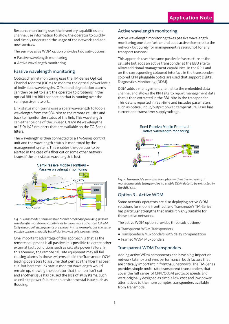
All these options are extremely compact and are totally passive requiring no power, thus helping the network operator with their cost reduction goals. Passive WDM networks can support optical paths of up to approximately 80 km and are therefore highly attractive for mobile fronthaul networks.
Fig. 5 Transmode’s passive Mobile Fronthaul featuring the TG-Series based passive WDM option enabling low – or even no – power consumption.
As the RRH to BBU connection is now over a long distance of outside plant fiber, consideration should be taken to protect this against fiber cuts and other faults. Some purely passive WDM systems just comprise of optical filters and are not able to address this challenge. But the TG-Series can address this challenge with the Fiber Protection Unit.
This unit splits the signal into two identical signals which can then be routed around diverse routes around the network to the far end where a second unit recombines the signals and switches between them in case of a network failure such as a fiber cut. This can be used on both point-to-point and ring architectures.
Option 2 - Semi-Passive WDM Adding monitoring capabilities One potential drawback of a purely passive approach is that by the passive nature of the solution there is limited management capabilities beyond inventory management through the Enlighten™ management suite.
To address the requirement for more advanced Operations, Administration and Maintenance (OA&M) capabilities, Transmode has extended the passive option to include active monitoring capabilities.
These capabilities address three main areas of functionality; resource monitoring, optical channel monitoring and link status monitoring. All these performance statistics can be monitored in Transmode’s multi-layer management suite Enlighten.
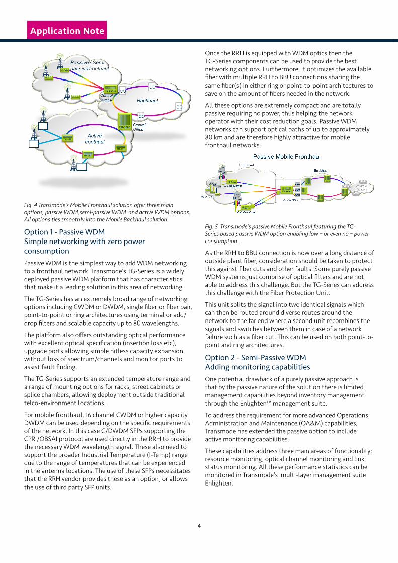
Fig. 4 Transmode’s Mobile Fronthaul solution offer three main options; passive WDM,semi-passive WDM and active WDM options. All options ties smoothly into the Mobile Backhaul solution.
Option 1 - Passive WDM Simple networking with zero power consumptionPassive WDM is the simplest way to add WDM networking to a fronthaul network. Transmode’s TG-Series is a widely deployed passive WDM platform that has characteristics that make it a leading solution in this area of networking.
The TG-Series has an extremely broad range of networking options including CWDM or DWDM, single fiber or fiber pair, point-to-point or ring architectures using terminal or add/drop filters and scalable capacity up to 80 wavelengths.
The platform also offers outstanding optical performance with excellent optical specification (insertion loss etc), upgrade ports allowing simple hitless capacity expansion without loss of spectrum/channels and monitor ports to assist fault finding.
The TG-Series supports an extended temperature range and a range of mounting options for racks, street cabinets or splice chambers, allowing deployment outside traditional telco-environment locations.
For mobile fronthaul, 16 channel CWDM or higher capacity DWDM can be used depending on the specific requirements of the network. In this case C/DWDM SFPs supporting the CPRI/OBSAI protocol are used directly in the RRH to provide the necessary WDM wavelength signal. These also need to support the broader Industrial Temperature (I-Temp) range due to the range of temperatures that can be experienced in the antenna locations. The use of these SFPs necessitates that the RRH vendor provides these as an option, or allows the use of third party SFP units.
4
Application NoteApplication Note
Resource monitoring uses the inventory capabilities and channel use information to allow the operator to quickly and simply understand the usage of the network and add new services.
The semi-passive WDM option provides two sub-options;
● Passive wavelength monitoring ● Active wavelength monitoring
Passive wavelength monitoringOptical channel monitoring uses the TM-Series Optical Channel Monitor (OCM) to monitor the optical power levels of individual wavelengths. Offset and degradation alarms can then be set to alert the operator to problems in the optical BBU to RRH connection that is running over the semi-passive network.
Link status monitoring uses a spare wavelength to loop a wavelength from the BBU site to the remote cell site and back to monitor the status of the link. This wavelength can either be one of the unused C/DWDM wavelengths or 1310/1625 nm ports that are available on the TG-Series filters.
The wavelength is then connected to a TM-Series control unit and the wavelength status is monitored by the management system. This enables the operator to be alerted in the case of a fiber cut or some other network issues if the link status wavelength is lost.
Fig. 6 Transmode’s semi-passive Mobile Fronthaul providing passive wavelength monitoring capabilities to allow more advanced OA&M. Only macro cell deployments are shown in this example, but the semi-passive option is equally beneficial in small cells deployments.
One important advantage of this approach is that as the remote equipment is all passive, it is possible to detect other external fault conditions such as cell site power failure. In this scenario, the remote cell site equipment may all fail causing alarms in those systems and in the Transmode OCM leading operators to assume that perhaps the fiber has been cut. But here the link status monitor wavelength would remain up, showing the operator that the fiber isn’t cut and another issue has caused the loss of all systems, such as cell site power failure or an environmental issue such as flooding.
Active wavelength monitoringActive wavelength monitoring takes passive wavelength monitoring one step further and adds active elements to the network but purely for management reasons, not for any transport reasons.
This approach uses the same passive infrastructure at the cell site but adds an active transponder at the BBU site to allow additional management capabilities. In the RRH and on the corresponding coloured interface in the transponder, colored CPRI pluggable optics are used that support Digital Diagnostics Monitoring (DDM).
DDM adds a management channel to the embedded data channel and allows the RRH site to report management data that is then extracted in the BBU site in the transponder. This data is reported in real-time and includes parameters such as optical input/output power, temperature, laser bias current and transceiver supply voltage.
Fig. 7 Transmode’s semi-passive option with active wavelength monitoring adds transponders to enable DDM data to be extracted in the BBU site.
Option 3 - Active WDMSome network operators are also deploying active WDM solutions for mobile fronthaul and Transmode’s TM-Series has particular strengths that make it highly suitable for these active networks.
The active WDM option provides three sub-options;
● Transparent WDM Transponders ● Transponders/Muxponders with delay compensation ● Framed WDM Muxponders
Transparent WDM Transponders Adding active WDM components can have a big impact on network latency and sync performance, both factors that are critically important in fronthaul networks. The TM-Series provides simple multi-rate transparent transponders that cover the full range of CPRI/OBSAI protocol speeds and were originally designed as simple low cost and low power alternatives to the more complex transponders available from Transmode.
5
Application NoteApplication Note

These transponders have the great advantage of extremely low latency, as low as 4 ns for a pair of 10G transponders, which is considered to be the best in the industry and is equivalent to adding just 1 meter of fiber to the route. They are also extremely transparent and support transparent synchronization making them very useful in mobile fronthaul networks.
Fig. 8 Transmode’s active Mobile Fronthaul using the active TM-Series transparent Transponders bringing key values such as low latency and superior sync.
This approach naturally adds back a small portion of the power consumption saved by the move to mobile fronthaul and C-RAN, but these solutions are very low power and still represent a significant overall power saving.
The small addition in power and space to add active WDM adds a number of advantages to the fronthaul network.
Firstly it removes the need for I-Temp CWDM CPRI/OBSAI SFP units in the RRH as the existing optics can be used to connect to the transparent transponder.
Also the addition of active WDM allows the network to be extended to greater distances or over more complex optical designs with higher insertion loss requirements, such as rings with many add/drop nodes or more complex ROADM based Flexible Optical Networks. Active WDM also allows the fronthaul network to be managed with functionality such as simple performance monitoring provided in Enlighten.
With this approach network operators can create a cost effective active WDM network for all CPRI/OBSAI signals, again over point-to-point or ring architectures with options for protecting traffic, which addresses the network operators key performance areas – compact, low power, ultra-low latency and transparent data/synchronization transmission.
Transponders/Muxponders with patented delay compensationThe Transponder/Muxponder with delay compensation option uses a mobile fronthaul specific set of 12-port units that can act as either multiple muxponders supporting up to 6 channels each or up to 6 individual transponders depending on the network requirements. Both cases support point-to-point and ring architectures. They also have a unique architecture that saves on expensive line interfaces.
Usually to provide a protected channel around a ring you need two independent optical paths, with a total of four end points. By using the Transmode architecture, operators can cut this to just three saving 25% of the cost associated with optics which makes up a substantial part of the overall network cost.
Fig. 9 Transmode’s patented approach to ring architectures with delay compensation saves 25% of the pluggable optics costs.
One challenge however of ring architectures for CPRI traffic is that the two optical paths must have identical latency characteristics to ensure that there is no change in latency if there is a protection switch.
The patented approach constantly monitors the latency of both paths and ensures the short path is correctly delayed to match the latency of the longer path. As this is done in real-time the network can cope with changes in latency due to effects such as temperature which is especially important in fronthaul where sometimes above ground fibers are used.
The two units that support this approach have industry leading mobile fronthaul performance such as 0.6-14 Gbit/s support, 4 µs latency for the Muxponder and 2 µs latency for the Transponder (per pair of units) and sub 15 ms switchover time. The non-hardened variant of the Muxponder or Transponder fits into any TM-Series chassis for use in the BBU or suitable equipped RRH sites and the hardened unit sits in non-controlled environments such as street and wall cabinets. These hardened units have a broader temperature range support (-40 to +65 °C) and features such as external alarm contacts.
Framed WDM MuxpondersThe Framed WDM Muxponders option multiplexes multiple lower speed CPRI/OBSAI signals onto a single wavelength to further optimize the network.
These muxponders are typically used in demanding networking applications and use a more complex framed signal format adding overhead to the data payload. This overhead adds capabilities such as in-band management channels and more sophisticated performance monitoring.
However, adding this overhead to the data can have a significant impact on the latency and the transparency of the data and synchronization.
Transmode’s Intelligent WDM (iWDM™) Muxponders use
6
Application NoteApplication NoteApplication Note

App
licat
ion
Not
e_M
obile
Fro
ntha
ul_G
a patented approach to this challenge that maintains synchronization transparency and keeps low latency performance at just 8 microseconds per unit. In fact Transmode’s Fronthaul Muxponder can support up to 3x 2.5G (CPRI-3) or 3G (CPRI-4) signals plus 2 or 1 Synchronous Ethernet signals, all with independent synchronization domains over the same 10G line. This is very difficult to achieve with other approaches to framed WDM signals.
Fig. 10 Transmode’s active Mobile Fronthaul option using framed Muxponders.
The key advantages of taking this step is that Muxponders can further enhance the utilization of the network by multiplexing multiple 2.5G (CPRI-3) or 3G (CPRI-4) signals on to a 10G wavelength and the enhanced management capabilities.
The additional Synchronous Ethernet signals can be used for co-located small/macro cells that are using Ethernet backhaul as opposed to CPRI/OBSAI fronthaul or other Ethernet based data.
The practicalities of deployment; mixing up fronthaul and backhaul
Transmode’s passive TG-Series and active TM-Series platforms have many factors that make them particularly suitable for mobile fronthaul networks but deployment of fronthaul is often not as simple as looking at the fronthaul in total isolation within the wider network.
When looking at a specific geographic area that requires mobile fronthaul, there will be traffic over the same region that is traditional mobile backhaul traffic.
Some cell sites will maintain the traditional RRH/BBU colocation while others migrate to a fronthaul architecture. Some will be macro cells while others are small cells or aggregation points for small cell traffic. Even if a complete network migrates to a fronthaul architecture the cell sites furthest away from the core nodes will have a fronthaul network to a central office. This fronthaul network is then “backhauled” over the same network as the fronthaul traffic for those nodes that are closer to the core.
Of course it is possible to totally separate fronthaul and backhaul networks with completely separate infrastructure. But this is unnecessary and more costly.
This application note will not discuss Transmode’s mobile backhaul solutions in detail as they are well documented elsewhere (see further reading). Both the mobile fronthaul and the mobile backhaul solutions are managed with the same management system; Transmode’s multi-layer management suite Enlighten.
Transmode’s Mobile Fronthaul solution can carry legacy mobile backhaul traffic as alien wavelengths.
Fig. 11 Mobile Fronthaul and Mobile Backhaul networks overlapping. Transmode has solutions in both areas, both based on the same TM-Series platform providing synergy benefits.
In conclusion
Centralized-RAN, Cloud-RAN and mobile fronthaul are emerging technology trends that have a great potential in helping address the ongoing rapid growth in mobile traffic. Optical networking and Transmode’s solutions in particular can play an important role in meeting the goals of these network architecture initiatives. However, the technical challenges in meeting the strict latency and synchronization requirements of these networks makes this difficult to achieve for many systems vendors.
Transmode’s strengths in signal and synchronization transparency, its wide support of the CPRI/OBSAI rates and broad passive and active WDM product range provides network operators with a robust toolkit to address the challenges presented by these network.
Transmode’s solutions provide passive, semi-passive and active options each with unique advantages to the network operator.
Once an option is chosen, it can be easily mixed with Transmode or legacy mobile backhaul if required.
The specifications and information within this document are subject to change without further notice. All statements, information and recommendations are believed to be accurate but are presented without warranty of any kind. Contact Transmode for more details.
www.transmode.com
Application NoteApplication NoteApplication Note