mobile stairclimber t09 roby · 8.1) control handle assembly and clamping a) place the control...
TRANSCRIPT

MOBILE STAIRCLIMBER
T09 "ROBY" USE AND MAINTENANCE
Baronmead International Limited
Unit 1, Flansham Business Centre
Hoe Lane, Flansham, Bognor Regis
PO22 8NJ.
www.baronmead.com Tel 01243 586692

CE DECLARATION OF CONFORMITY The Manufacturer:
VIMEC, Via Parri n. 7, 42045 Luzzara (R.E.) ITALY declares on its own responsibility that the mobile Stairclimbers for the transport of person on wheelchair model: T09
comply with the following European Directives: • Directive 89/336 "Electromagnetic Compatibility" as modified by Directive 92/31/CE • Directive 93/42 "Medical Devices" (Category I) Managing Director
Ing. Pier Franco Linari Luzzara, 01/02/2006
1
USE AND MAINTENANCE GENERAL CONTENTS 1. Unit and manufacturer identification Page 3
2. Service Page 4 3. Description of unit Page 4
4. Technical data Page 7 5. Permitted use of the unit Page 9
6. Transport Page 10 7. Preparation for use Page 11
8. Preparation for daily use Page 13 9. Maintenance Page 21
10. Vibrations - aerial noise of unit Page 23 11. Information about components and materials disposal Page 24
12. Instruction summary. Page 25 13. Reversing wheelchair handle clamps Page 27
STAY SAFE! ATTENTION This symbol indicates important instructions for safety.
While all the instructions are important, please pay particular attention to these. Carefully read this manual before undertaking the assembly, use and maintenance of the unit. 2

Pay due care and attention while operating this machine to minimise the risk of accidents. Follow all the instructions for the T09 including all the stickers applied to the unit. Immediately replace any damaged stickers. Only trained staff are to operate the unit. Observe the Training level for different activities with reference to the following symbols: O Trained operator OS Manufacturers authorised agent The unit should only be used by a RESPONSIBLE ADULT who is trained in all operating functions described in this manual.
1) UNIT AND MANUFACTURER IDENTIFICATION
3
2) SERVICE
To arrange a service for your T09 stairclimber, please contact Baronmead on Tel 01243 586692
3) DESCRIPTION OF UNIT 3.1) Description Chassis - Fig. 1/a It is composed of: - light alloy frame & plastic cover It contains: · Motor & gearbox · Tracks; · Transit wheels for level surface use; · Electrical control system. · Battery; · Integral battery charger. On the chassis control panel you can find the following: - Control handle release lever (Fig. 2\a); - Plug for battery charger (Fig. 2\b); - Battery charge condition indicator led (Fig.2/c). - Rocker switch to drive base unit (Fig. 2/d);
4
Control handle - Fig. 3/a The control handle secures the wheelchair onto the stairclimber while on the stairs or on landings. The control handle also has the main controls to drive the mobile stairclimber. It contains: - Wheelchair attachment clamps (Fig. 3/c); -Height and width adjustable attachment clamp cross member (Fig. 3/d); - Wheelchair wheels support cross member (Fig. 3/e); - Adjustable headrest (Fig. 3/b); - Automatic electrical connector for the chassis (Fig. 3/f). The drive control panel (Fig.4/f)
includes:
- Up / Down pushbuttons (Fig. 4\a); - Emergency stop switch (Fig. 4\b); - Gradient indicator (Fig. 4\c); -Battery discharge indicator (Fig. 4\d): · Flat battery - slow flash; · Motor high temperature – fast flash; · Motor jammed - double fast flash compared to motor high temperature. - “ON/OFF” key (Fig. 4/e).
5
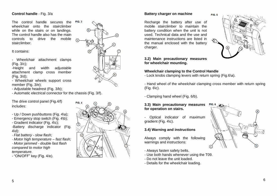
Battery charger on machine Recharge the battery after use of mobile stairclimber to maintain the battery condition when the unit is not used. Technical data and the use and maintenance instructions are listed in the manual enclosed with the battery charger.
3.2) Main precautionary measures for wheelchair mounting. Wheelchair clamping to the Control Handle - Lock knobs clamping levers with return spring (Fig.6\a). - Hand wheel of the wheelchair clamping cross member with return spring (Fig. 6\c). - Clamping hand wheel (Fig. 6/b). 3.3) Main precautionary measures for operation on stairs. - Optical indicator of maximum gradient (Fig. 4\c). 3.4) Warning and instructions Always comply with the following warnings and instructions: - Always fasten safety belts. - Use both hands whenever using the T09. - Do not leave the unit loaded. - Details for the wheelchair loading.
6

3.5) Operating position The operator should always be behind the Control Handle, firmly holding the handles (Fig. 4/f).
3.6) Components
- Chassis (Fig. 1\a). - Control Handle (Fig. 3\a). - Charge cable (Fig. 5/a). 3.7) Technical standards The unit complies with the following standards: STANDARD 93/42/CEE Concerning medical devices. STANDARD 89/336 Electromagnetic compatibility as modified by Standard CE 92/31. 4) TECHNICAL DATA - Drive gear
Irreversible Worm Screw reduction gear Ratio 1/50 Toothed belt with rubber tracks HTD-8M Driving pulley z=40 Transit wheels for the transfer on the level n° 4 wheels on ball bearings - Performance
Running direction Forward/Backward Speed (upwards/downwards) 5 m/min. Capacity 1 person with wheelchair Rated load 130 kg Geometrical features of the stair See Fig. 8
7
- Environmental conditions Temperature 0° - +45°C Humidity -max. 90% - Overall dimensions Machine body See Fig. 7 Control Handle See Fig. 7 - Weight Machine body kg 37 Control Handle kg 10 - Electrical installation D.C. Motor Brushless 24V Electrical input 25 A Battery charger on machine 230V AC 50 Hz to 24V DC 3A Non spillable AGM battery 2x 12V 12Ah Battery recharge time 8 hours from flat Fuse 40 A - Controls Timed start push button (Forward/backward) Delay of 1 second Emergency stop push button (Fig. 4/b) - Indicators Battery charge display (Fig. 4/d) Gravity gradient visual signal (Fig. 4/c)
8
Fig. 7

5) Permitted use of the unit
5.1) Permitted use Mobile stairclimber Model T09, has been designed for the transport of disabled persons on manual self propel wheelchair on staircases with the following features: - Environment: Indoor/outdoor - Steps: Parallel, without coatings - Gradient: Maximum 35° (Fig. 8/a) - Step-riser height: Maximum 180 mm, min. 100 mm (Fig. 8/A) - Step nose radius: From 0 to 20 mm (Fig. 8/R) - Attendant: Always present and with the following characteristics: A physically and mentally suitable adult, familiar with the operation of the equipment and maintenance instructions.
9
5.2) Unsuitable environments Environment: Potential problems Use on staircases with gradient over 35°: Instability, tracks skidding Use on steps with riser height over 180 mm: Instability, tracks skidding Use on steps with riser less than 100 mm: Tracks skidding Use on steps with a nose radius higher than 20 mm: Tracks skidding Un-trained operator: Potential Instability Transport of Power chairs Not suitable Transport of people or things not seated on the wheelchair Not suitable Use on wet or icy stairs: Instability, tracks skidding Use in water or in rain: Electric installation failure Use on staircases with non parallel steps: Instability, lateral tilting
WARNING: DO NOT MODIFIY FOR UNINTENDED USES.
6) TRANSPORT 6.1) Handling
The dismantled unit can be carried or for loading / unloading. The base section can be carried by using the handles on either end (Fig. 9\a and b). Base weight complete with battery: 37 Kg Control Handle weight: 10 Kg For ergonomic reasons, the base will need to be lifted by two people. 6.2) In When not in use: - Place the machine in a dry room. - Cover to protect from dust / dirt. - Never leave the machine open to the weather.
10

6.3) Position of the centre of mass (Fig. 10\a) It is located between the Control Handle and the chassis when assembled. 7) PREPERATION FOR USE 7.1) Initial Set up. Before setting up, read the manual carefully. Package opening
- Cut the protective film by using a knife. Do not cut or heat the box. - Take care not to damage the surfaces of the unit. - Clean the unit, taking away all residual packaging and dust. 7.2) Disposal of package material Dispose of the packaging responisbly.
7.3) Preliminary checks Checks to carry out before using:
Competence: OS - Manufacturers authorised agent. 11
MACHINE CHECK: Check the following for correct function. Control Handle: - Correct clamping of the Control Handle (Fig. 11): - Wheel chair catches (Fig. 6/a): Smoothness, safe return to the lock position. - Safety belts: Condition, security and catch operation. - Controls: Correct action of the controls; Correct timing of the controls; Efficiency of the emergency stop (Fig. 4/b). - Indicators: Efficiency of the battery charger signal (Fig. 4\d); Efficiency of the gradient indicator (Fig. 4\c). Machine body: - Battery charger: Voltage and frequency as in paragraph 7.5.
7.4) Environmental conditions for the operating location. - Temperature: From 0 °C to +45 °C
- Humidity: Max 90%
12

7.5) Electrical connection The input for the battery charger is an IEC socket. The user should connect the battery charger to a supply conforming to the standards for the civil use electrical units, equipped with an
appropriate switch. Battery charger data: - Input Voltage: 230V ac. - Frequency: 50 Hz - Output Voltage: 24 V dc / 3A 8) PREPARATION FOR DAILY USE 8.1) Control Handle assembly and clamping a) Place the control handle (Fig. 11/a) carefully on the mounting bar (Fig.
1/b) on the base. b) Incline the control handle (Fig. 12/a) as shown by the arrow (Fig. 11/b) until it is locked to the base. c) Once the control handle is locked (Fig. 12/a), protect the release lever pushing on the cover (Fig. 12/b).
WARNING: Ensure that the safety cover is in its proper position. In this position, the safety switch is activated and the Control Handle is locked in the work position. To switch on the machine, insert the key (Fig. 4/e); the push buttons (Fig. 4/a) on the
Control Handle allows the operating of the tracks forwards - backwards. * If the red cover is not in its proper position, drive of the machine is inhibited. 13
8.2) Control Handle release To release the control handle (Fig. 13/a) ,lift the red safety cover (Fig.13/b) and then, while the release pedal (Fig. 14/b) is being pressed, push the control handle (Fig. 14/a) forward as shown by the arrow (Fig. 14/c).
8.3) Wheelchair clamping a) Insert the key (Fig. 15/a) for stair climber activation into its appropriate socket
(Fig. 15/b). b) Lock the wheelchair brakes. By pressing down on the control handle, tilt the mobile stairclimber back onto its transit wheels and push it under the wheelchair (Fig. 16/a). c) Holding the control handle (Fig. 13/a), lift the red cover (Fig. 13/c) with your foot, exposing the handle release lever (Fig. 13/b). d) Press the lever (Fig. 14/b) downwards in order to release the control handle (Fig. 14/a) and, push it forward (Fig. 14/c), bring it to the wheelchair seat back (Fig. 16/c). e) Unscrew (Fig. 17/b) the knob (Fig.
17/a) placed on the rear face of the control handle, push the metallic central pushbutton (Fig. 17/c) and slide the arms (Fig. 17/d) until they are brought under the handgrips of the wheelchair (see Fig. 16). NOTE: Carry out this operation holding
the crosspiece as shown in Fig. 17/e. 14

f) Adjust the handle clamp width (Fig. 18/a) according to the wheelchair handle width: unscrew the knob (Fig. 18/b) and move the handle clamp sideways (Fig.18/c). Repeat for the other side. g) Grasp the plunger (Fig. 19/a) by hand and lift it. Then swing the hook (Fig.19/b) past the plunger and hook it to the wheelchair frame (see Fig.16/e), then release the plunger and ensure that the hook can’t open, Repeat for the other side.. Finally, tighten the knobs (Fig. 18/b).
IMPORTANT: do not clamp handles or other objects that are not firmly attached to the wheelchair.
h) Lean the control handle back (Fig.
11/b) until it can be locked to the drive unit. For this operation it’s possible to place your foot on the bar provided on the base unit (Fig. 16/f). i) Close the safety cover (Fig. 12/b) by foot. j) Now the machine is ready (the
green led on the control handle cover will light up when drive switches are pressed and the wheelchair is properly locked and anchored to the stair climber). k) Pressing downwards on the control handle the transit wheels are activated and the first step of the flight can be reached to perform the
climb or descent (Fig. 27 and 29). WARNING: Always fasten the seat belt before use.
15
WARNING: Hold the Control Handle firmly, even when on level ground, when a passenger is on the machine.
8.4) Travel preparation
a) BATTERY: Check the battery state after having assembled the machine; activating drive for a moment when the machine is empty (with no one on board). The use of the machine when the indicator led is blinking
could damage the battery.
b) SIGNALS: Do not use the mobile stairclimber on unfamiliar stairs before checking the gradient indicator. If the gradient indicator does not work, DO NOT USE THE TRACK MOBILE STAIRCLIMBER! Call Baronmead operative
immediately.
c) EMERGENCY: Check the emergency STOP operation (red push-button on control panel).
- Press the push-button: the drive controls should be inhibited. - Reset the push-button pulling it out. If the emergency STOP does not work, DO NOT USE the mobile stairclimber! Call Baronmead operative immediately.
Do not move the mobile stairclimber with a person on board before carrying out all operations described in paragraph 8.3.
16

NEVER LEAVE THE MACHINE UNATTENDED WITH A PASSENGER ON BOARD. 8.5) Manual operation on level surfaces
To move quickly over longer distances and to turn the machine, it is necessary to operate manually: a) Using the Control Handle as a lever, raise the tracks off the ground to allow the machine to roll on its transit wheels. b) Push the unit in the desired direction. 8.6) Stair gradient check
This check should be done on all new locations. a) Check that the step riser
is not greater than 180 mm (Fig. 8). b) Operating manually, without person
on board, on approaching the first stage of the stair to travel, press the push button control (Fig. 4/a), travel on a section of stair, release the push button and make sure that the gradient indicator placed (Fig. 4\c) on the Control Handle is green (Gradient under 35°). If the indicator is red (Gradient above 35°), it is not possible to travel on that staircase. Green indicator: correct gradient Red indicator: excessive gradient 8.7) Headrest adjustment To adjust the headrest (Fig. 20/a): Remove the headrest and adjust it using two Velcro stripes (Fig. 20/b). 17
WARNING: THE MOBILE STAIRCLIMBER OPERATOR DETERMINES THE STABILITY OF THE UNIT. TO AVOID UNSTABLE CONDITIONS PLEASE FOLLOW THE POINTS BELOW.
8.8) Operation on staircase The unit should be always placed so as the control handle is towards the upward side. If during the stair operation, the mobile stairclimber continues to operate when the push button is released, press the emergency STOP red push
button on the Control Handle control panel. Afterwards follow section 8.9. 8.8.1) Stair ascent operation a) Operate manually as in section 8.5. Advance the mobile stairclimber with the person on board to the first step of the flight (Fig. 21/a). - If you must travel just one flight, position the mobile stairclimber in the middle of the staircase. - If there is more than one flight of stairs, travel as near the inside handrail as possible or near the inside wall; this position makes manual operation on landings easier.
The mobile stairclimber should be perpendicular to the steps; it is not possible to travel on staircases diagonally. b) Press the “up” push button holding the Control Handle firmly
with two hands, travel up the flight until the STOP sticker(Fig. 22/a) aligns with the nose of the last step (Fig. 22/b).
18

c) Release the drive button, and lower the Control Handle slowly (Fig.22/c). If the staircase comprises two or more flights, operate manually and approach the second flight. Repeat the previous operation.
WARNING: The lugs on the tracks can slide on the step nose during operation and while resting on the staircase. In extreme circumstances, this could cause the mobile stairclimber to tip forward. For this reason, firmly hold the Control Handle firmly, even when stationary, whenever a
passenger is transported. 8.8.2) Stair descent operation a) Operate manually as in section 8.5. Approach the first step (Fig. 22/b) of the flight you must travel on, until the mobile stairclimber has arrived with the message STOP at the beginning of the flight (Fig.22/a). - Stair with one flight: Locate at the centre of the staircase, with the machine placed in axis to the staircase. - Stair with more flights: Place the unit towards the stair well inner edge, taking care of being in square with the staircase (see 8.8.1a).
WARNING: The machine should be always perpendicular to the step. b) Raise the Control Handle (Fig. 22/d) until the tracks have
touched the lower step, press the downwards push button and travel down the stairs taking care to hold the Control Handle firmly in both hands. c) At the end of each flight, the side mobile wheels (Fig.23/a) will
automatically position for the next manual operation. 19
WARNING: there is the possibility that the track lugs may slide on the nose of the stair during the operation of the mobile stair climber. This could cause the mobile stairclimber to tip forward. For this reason, firmly hold the Control Handle, even when on
level ground, when the user is transported. 8.9) Emergency stop on the staircase
In case of an emergency stop on a staircase flight, do not release the control handle When the unit is locked, make sure of the vehicle stability before leaving the Control Handle.
If the track mobile stairclimber stops in the upward direction due to discharged battery, it is possible to rescue the passenger by reversing the direction and bringing him to the lower level.
8.10) Passenger release a) At the end of the journey, release the Control Handle. b) Push the Control Handle forwards until the wheelchair touches the ground. c) Raise plunger (Fig. 24/a) and retract red lever (Fig. 24/b) outwards. Loosen handwheels (Fig. 25/a). d) Lower the Control Handle and re-clamp it to the chassis. e) Remove the mobile stairclimber manually from under the wheelchair.
20

8.11) Passenger recovery
IMPORTANT: in case of an emergency stop on the stairs, it is
absolutely forbidden to release the Control Handle. If the mobile stairclimber stops when in the upward direction due to discharged battery, it is possible to rescue the transported user by reversing the direction and bringing him back to the
lower level.
WARNING: if it’s not possible to come back to the lower floor, move the machine by using the handle control device for
its handling (Fig.26/a) supplied in equipment. 9) MAINTENANCE
The unit requires maintenance and service by an approved operative every six months. It is very important to check the following parts regularly: Competence level: O - Trained operator Detail / Component Check frequency a) Rubber tracks monthly b) Control Handle clamping monthly c) Wheelchair clamping monthly d) Battery before every use e) Control Handle connector monthly f) Electrical loom & fuses monthly g) Indicators before every use h) Emergency STOP switch before every use The tests to carry out for every point a).....f) are the following: a) The tracks must not show any wear or cuts or lugs excessive wear. 21
b) Make sure that the wheelchair release mechanism is intact and in working order. c) The batteries are sealed and maintenance free. They must be kept on charge by connecting the battery charger using the cable supplied, during the periods when the machine is inactive. d) Check the IEC charger socket is undamaged. e) Check that the status light on the control handle is activated shortly after pressing the up / down buttons. f) Check the emergency STOP red button operation. Push the red button: the controls should be deactivated. Reset the push button pulling it upwards.
If the result of every check is not positive, contact BARONMEAD agent. See chapter 2.
9.1) Periodic cleaning of the unit Competence: O - Trained operator Frequency: Quarterly In operations that require the removal of the covers, switch off at the mains and remove the charge cable before proceeding. In order to maintain reliable operating, it is necessary to keep the machine clean both inside and out. Cleaning instructions: - Turn off the mains supply and remove the power cable. - Remove the covers by unscrewing the 8*fixing screws. - Remove dust, dirt and grease marks.
22

- At the end of cleaning, replace the covers and reconnect the mains connector. Battery charger: When the battery charger reaches the yellow led (Fig.27/a) the machine can be used because the battery has reached the 3/4 of its charge. Every 7 or 8 partial charges it’s good thing, in order to save the battery, to carry out the complete battery charge until the green led is reached (Fig.27/b) (after about 11 hours of charge).
It’s not possible to use the machine while charging the battery. 9.2) Defects - Possible causes – Possible cures
Competence: O - Trained operator Defects Possible causes Possible cures The unit does not Starting key Insert the ON/OFF key move in either direction. Emergency STOP “in” Pull out Handle lock up (fig. 14) Press down Discharged battery Recharge Damaged battery Replace Discharged battery Safety lock out at a charge percentage of 10% If the malfunction persists, contact a BARONMEAD operative. 10) UNEXPECTED MOVEMENT AND NOISE OF THE UNIT a) Unexpected movement As every staircase can have different pitch, occasionally the T09 will move downward slightly while operating due to the track lug not engaging fully with the stair nose this is: - infrequent with moderate acceleration; 23
-momentary disruption for the operator and passenger as the next lug locates on the stair nose. This does not affect the safe operation of the machine. b) Aerial noise: less than 70 db. 11) INFORMATION ABOUT PARTS AND MATERIALS DISPOSAL a) Rubber and plastic materials disposal Dispose of used parts responsibly in accordance with the local regulations in force; contact your local council if in doubt. b) Battery disposal Where possible, recycle batteries at an authorised recycling site, if this facility is not available, dispose of responsibly in accordance with the local regulations in force, contact your local council if in doubt.
24

12) Instruction Summary
12.1) Descent 1st phase: Once the wheelchair is
properly locked (the green light must be lighted up on the panel), by a soft pressure downwards (Fig. 28/b), on the control handle, lift the nose of the machine (Fig.28/d), activating the transit wheels (Fig. 28/c). In this way it’s possible, with little effort, to move
the machine to the edge of the first stair of the flight (Fig. 28/a). 2nd phase: Activate the down pushbutton until the STOP sticker (placed on the base of the cover) lines up (Fig.29/a) with the edge of the first stair (Fig.29/b).
3rd phase: gently tilt the machine forward (Fig. 29/c) until the tracks are resting on the stairs. Now, press the down pushbutton (remember that the start is delayed of about one second), the machine will start to descended the stairs. 25
4th phase: When end of the flight is reached, drive until the machine is flat, press the control bar downwards again to activate the transit wheels, then at the same time, push and turn the machine placing it again on the edge of the first stair of the next flight (see Fig. 30), paying attention to stop on the STOP. Now the 3rd phase can be carried out again.
WARNING: ALWAYS HOLD THE CONTROL HANDLE FIRMLY!
12.2) Climb 1st phase: Remember that moving the machine on the plane it’s required to exert a soft pressure downwards on the control handle (Fig. 31/b), bring the machine to the first stair of the flight (Fig. 31/a) taking care of keeping the machine square to the staircase. 2nd phase: Now keeping the up pushbutton pushed (remember that the start is delayed of about one second), start the climb.
3rd phase: Once the last stair is reached, stop the machine when the STOP sticker (placed on the base of the truck) (Fig. 32/a) aligns with the edge of the stair (Fig.32/b), then gently lean the machine onto the landing, tilting the machine as shown in Fig. 32/c. 4th phase: When the top of the flight is reached, once the machine is flat,
press downwards on the control handle again to activate the transit wheels, then, at the same time, pull and turn the machine bringing it to the first stair of the next flight,
26

paying attention to place it square to the staircase (see Fig. 33). Now, climb
the next flight or, if the final destination is reached, release the wheelchair. WARNING: ALWAYS
HOLD THE CONTROL HANDLE FIRMLY! 13) REVERSING WHEELCHAIR HANDLE CLAMPS on the market, there are not only wheelchairs equipped with push handles (Fig. 34/a) but also wheelchairs in which the push handles are replaced by a cross bar (Fig.35/a) placed in the rear part on the seat back. In these cases the safety couplings (Fig. 36/a), because it is equipped with a second hole (Fig.
36/b), can be rotated of 90° so that the red hook (Fig. 36/c) grasps the shackle from below and not sideways, clamping the wheelchair to the control handle with the same
safety of the traditional wheelchairs. In order to carry out this operation follow this procedure: 1) Remove the clamping screw placed in the end of the control handle arm (Fig.36/d) and loosen the locking hand-wheel (Fig. 36/e); 2) Extract the safety clamp (Fig. 36/a) toward the outside (Fig. 36/f); 27
3) Rotate the safety coupling (Fig.37/a) by 90° (Fig.37/b), to the left for the left one and to the right for the right one; 4) Insert the rotated coupling (Fig. 37/c) onto the arm (Fig.37/d). Re-screw the setscrew into the end of control handle arms. 5) Bring the control handle (Fig.38/a) to the seat back of the wheelchair
(Fig.38/b). Pull the safety plunger (Fig. 38/c), hook the shackle (Fig. 38/d) using the hook (Fig. 38/e) and release the plunger (Fig. 38/c). NOTE: ensure that the plunger (Fig. 38/c) is placed under the red hook (Fig. 38/e) so that it can’t be released from the wheelchair (Fig. 38/d);
6) Lock the coupling turning the hand-wheel (Fig. 38/f). 7) Lift the arms (Fig. 38/g) until the point in which the red hook (Fig. 38/e) is placed in contact to the shackle (Fig. 38/d) is reached.
28

29 Base Drive Unit 7801211
30

Base Drive Unit – 7801211.1 Part Code Qty. Description
1 4294642 1 RH GUIDE
2 4294643 1 LH GUIDE
3 3702021 2 WHEEL
4 3702020 2 WHEEL
5 1004017 2 NO STEP Sticker
6 12389 4 5x15x1 WASHER
7 11062 2 M8x35 SCREW
8 2824457 1 GUARD
9 1304325 1 PIN
10 992004 2 SPACER
11 12041 2 RING
12 6064163 2 VIMEC ADHESIVE LABEL
13 11053 8 M5x12 SCREW
14 12959 2 M8 NUT
15 10433 4 M8x16 SCREW
16 804035 2 PULLEY
17 12956 4 8,4x17x1,6 WASHER
18 1044147 2 WHEEL
19 2864208 1 LH BRACKET
20 2864209 1 RH BRACKET
21 804027 2 PLULLEY
22 10907 4 M6 NUT
23 2864210 2 BRACKET
24 714016 2 SPRING
25 12809 1 6x6x20 TANG
26 12800 2 5x5x50 TANG
27 904262 2 SPACER
28 12170 2 RING
29 2384099 1 DRIVE SHAFT
30 1044146 1 GEARWHEEL
31 992027 2 20x28x1 WASHER
32 12052 4 RING
33 1022095 3 BEARING
34 12906 3 RING
31
35 1004019 2 STOP ADHESIVE
36 6014005 1 REDUCTION GEAR
37 2384100 1 REDUCTION GEAR SHAFT
38 1044145 1 GEARWHEEL
39 12993 2 M6x30 SCREW
40 10435 6 M8x20 SCREW
41 12807 1 A6x6x45 TANG
42 12909 3 8x32x2,5 WASHER
43 12943 1 5x5x20 TANG
44 10190 4 M6x20 SCREW
45 12373 4 6,4x12,5 WASHER
46 11055 4 M6x35 SCREW
47 2594470 1 PLATE
48 2304758 1 PLATE
49 10079 7 M3x10 SCREW
50 2304761 1 PLATE
51 12992 2 M6x40 SCREW
52 782012 1 ELASTIC BELT
53 7007426 1 EMERGENCY MOVE KIT
54 12956 1 8,4x17x1,6 WASHER
55 6882008 1 PLATE
56 484031 1 CAP
57 1004018 1 ITALY FLAG LABEL
58 10529 4 M5x16 SCREW
59 824005 2 TRACK
60 10396 4 M5x10 SCREW
61 904273 2 SPACER
62 904276 2 SPACER
63 6882004 1 SUPPORT
64 12918 2 A5x5x15 TANG
65 10316 2 8x24x2 WASHER
66 1004021 1 STICKER
32

Control Handle - 7801212
33
Part Code Qty. Description
1 10007 1 M3 NUT
2 6064342 1 KEY-RING
3 10673 4 3,5x13 SCREW
4 28941117 1 PROFILE
5 482019 2 SUPPORT TERMINAL
6 4254562 1 WHEELCHAIR WELDED COUPLING
7 782020 1 SAFETY BELT
8 3424422 1 M8 120x18x5 PLATE
9 28941118 1 PROFILE
10 482020 2 CAP
11 11052 2 M8x12 SCREW
12 28941128 1 RH BLOCK
13 4692004 2 M8x25 BALL GRIP
14 1304028 2 PIN
15 164105 2 BUSH
16 1004016 2 ADHESIVE LABEL WITH ARROW
17 2564055 2 BRACKET
18 902007 2 BUSH
19 4692006 2 BALL GRIP
20 12376 2 10,5x21 WASHER
21 10378 2 M10x45 SCREW
22 28941130 1 LH BLOCK
23 12956 2 8,4x17x1,6 WASHER
24 12941 2 WASHER
25 10648 4 4,2x9,5 SCREW
26 2304798 1 PLATE
27 2864941 1 PLATE
28 11053 1 M5x12 SCREW
29 6064329 1 INSTRUMENT BOARD STOP ADHESIVE
30 1044033 1 WHEEL
31 6064309 1 KEY ADHESIVE
32 6064330 1 PLATE
33 10990 4 6,3x19 SCREW
34 4694002 1 BALL GRIP
35 12188 1 RING
36 1304329 1 PIN
37 12984 1 20x28x0,5 WASHER
38 712053 1 SPRING
39 12376 2 10,5x18 WASHER
40 10033 2 M10 NUT
41 28941108 1 SUPPORT
42 874150 1 RUDDER INSTRUMENT BOARD
43 404039 2 VELCRUM
44 10239 1 M3x25 SCREW
45 10945 2 M10x35 SCREW

Base / Handle coupling - 7801213
35
Base / Handle coupling - 7801213.1
Part Code Qty. Description
1 2784359 1 STRUCTURE
2 4004167 1 RUDDER COUPLING/RELEASE DEVICE
3 12372 1 5,5x10 WASHER
4 712044 2 GRIPPING SPRING
5 904260 2 SPACER
6 1304325 1 PIN
7 164047 2 BUSH
8 10023 2 M8 NUT
9 992004 2 SPACER
10 12041 2 RING
11 3084070 1 CONNECTING ROD
12 10679 2 M6x10 SCREW
13 10698 4 3,5x13 SCREW
14 10433 2 M8x16 SCREW
15 11053 4 M5x12 SCREW
16 10081 2 M3x12 SCREW
17 484026 1 CAP
18 2255348 1 SHEATH
19 10005 1 M4 NUT
20 10007 3 M3 NUT
21 804035 2 PULLEY
22 1004014 1 BATTERY CHARGER ADHESIVE LABEL
23 2874195 1 PEDAL COVER
24 1304324 1 PIN
25 10518 2 M3x16 SCREW
26 1304326 1 PIN
27 2304814 1 PLATE
28 12054 2 FIXER
29 484030 1 CAP
30 712045 2 GRIPPING SPRING
31 10001 2 M3 NUT
32 12370 2 3,2x6 WASHER
33 12956 2 8,4x17x1,6 WASHER
34 11060 2 DOWEL
35 12959 2 M8 NUT
36 10027 2 M8 NUT
37 10893 1 M4x12 SCREW
38 6882009 1 PLATE

Loom components –7801215
Part Code Qty. Description
1 2255338 1 SHEATH
2 2262019 1 TAP+CABLE+PLUG
3 2255212 1 SHEATH
4 2255336 1 SHEATH
5 2255337 1 SHEATH
6 2255345 2 PUSHBUTTON
7 1802004 1 5 mm LED-HOLDER
8 1852003 1 PUSHBUTTON
9 1824010 1 PLUG KEY+RING
10 1902023 1 MICROSWITCH
11 1852018 1 PUSHBUTTON
12 8884908 1 FEEDER
13 1702003 2 BATTERY
14 1714092 1 24 V 0,5 Kw MOTOR
15 8884909 1 DISPLAY
37