mobius institute precision shaft alignment (master … · mobius institute precision shaft...
TRANSCRIPT

Mobius Institute Precision Shaft Alignment (Master Class)
(Practical Workshop Simulator Software )
In Cooperation with

Apply Methods to Develop Top Talents
Course Overview: When hands-on training is combined with the famous Mobius Institute 3D animations and simulations, you know that you
will enjoy a course that will leave you ready to take on any alignment challenge. You will develop an intuitive feel for the
alignment system because you understand the fundamentals and you have had a change to practice and ask questions.
Machines that have been precision aligned run longer, and cost less to run. Alignment greatly reduces the life of bearings,
seals, shafts and couplings.
This course will equip you with the knowledge and skills so that you can use a dial indicator tool or laser alignment system
to precisely align two components together. You will learn how to recognize misalignment and successfully set up the
alignment job.
After reviewing the important reasons for performing shaft alignment, we will discuss the pre-alignment checks and correc-
tions, including how to identify and correct soft foot.
What is unique about this course? Who Should attend: If you have to align machines, then you need this
course. If you own a modern laser alignment sys-
tem you have two choices: you can just set up the
lasers, enter the dimensions, take the readings
and do what the equipment tells you to do, or
you can understand what you are doing and be
prepared when things go wrong – and they will.
We will ensure you understand the entire process,
and give you the skills to return to the plant and
perform precision alignment. Note:
Although we will not have time to explain the op-
eration of every model of laser alignment system,
we will provide you with the knowledge so that
you will be successful with whatever model you
own.
Duration & Language :
Course Duration: 03 Days
Course Hour’s: from 08 am to 02 pm
Course Language: In English
Mobius makes it unique. We use 3D animations and software
simulators that completely demystify and demonstrate the align-
ment process – you need to see them to believe them! You will
completely understand the readings and the three-dimensional
alignment process. If you have previously performed shaft align-
ment, you will find that all of those steps and instructions will sud-
denly make a whole lot of sense – you will find yourself saying ‘Ah,
now I understand” (and “I wish I took this course years ago”).
Training Methodology :
The Course is in highly participative workshop
format with formal presentations, case studies
and interactive worked examples.
Each Learning Point is reinforced with
appropriate practical examples and exercises.

Module (01) Introduction of Shaft Alignment
1.1 The benefits of shaft alignment
1.2 A quick overview of the alignment process
Module (02) Shaft Alignment Mathematics:
A Primer Offset, Angularity and Alignment Mathematics
2.1 Introduction
2.2 Equal triangles
2.3 Triangles and alignment
2.4 A triangle from two offsets
2.5 Dealing with negative numbers
Module (03) Understanding Dial Indicators
3.1 Dial indicators
3.2 What can go wrong?
3.3 Zero the dial
3.4 Bar sag
3.5 Total Indicator Readings (TIR)
3.6 Hysteresis
3.7 Clock positions
3.8 Backlash
3.9 Why do we rotate both shafts?
3.10 Using dial indicators for shaft alignment
3.11 Using dial indicators for shaft alignment
3.12 Rim measurements
3.13 Face measurements
3.14 Axial end-play and float
3.15 Repeat all tests
3.16 Validity rule
Module (04) Pre-Alignment Checks and Corrections
4.1 Plan and review maintenance history
4.2 Why is the machine not aligned?
4.3 Installing a new machine
4.4 Decide on the required tolerance and coupling gap
4.5 Pipe strain
4.6 Mechanical looseness
4.7 Bent shafts and coupling runout
4.8 General preparations on site: Safety
4.9 General preparations on site: Clean up
4.10 General preparations on site: Shims
4.11General preparations on site: Jacking bolts
Course Outline: Module (05) Soft Foot Checks and Corrections
5.1 Detecting and Correcting Soft Foot
5.2 Introduction
5.3 Different types of soft foot
5.4 Rocking soft foot
5.5 Short foot - parallel air gap
5.6 Even foot
5.7 High foot
5.8 Bent foot
5.9 Squishy foot
5.10 Induced soft foot
Module (06) Why is soft foot important?
6.1 Why is soft foot important?
6.2 Shaft fatigue
6.3 Bearing distortion
6.4 Impact on the alignment task
Module (07) Testing for soft foot
7.1 Testing for soft foot
7.2 Taking soft foot measurements
7.3 Recording results
7.4 Using dial indicators to measure soft foot
Module (08) Correcting soft foot
8.1 Correcting rocking soft foot
8.2 Short cut number one: The Casanova method
8.3 Short cut number two: The 80% Rule
8.4 Using feeler gauges
8.5 Using a "stair" of shims
8.6 More complex shim patterns
8.7 Detecting and correcting induced soft foot
8.9 Mysterious soft foot
8.10 Summary
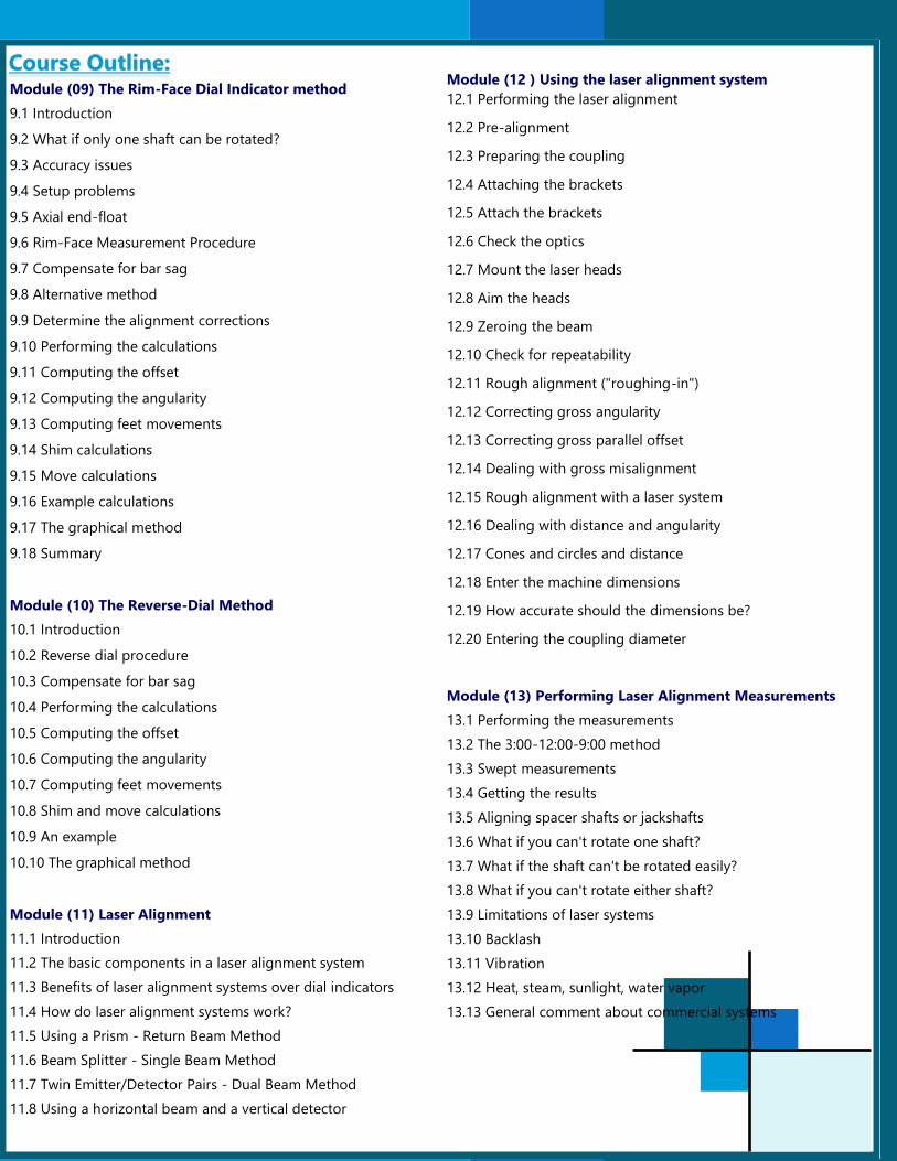
Module (09) The Rim-Face Dial Indicator method
9.1 Introduction
9.2 What if only one shaft can be rotated?
9.3 Accuracy issues
9.4 Setup problems
9.5 Axial end-float
9.6 Rim-Face Measurement Procedure
9.7 Compensate for bar sag
9.8 Alternative method
9.9 Determine the alignment corrections
9.10 Performing the calculations
9.11 Computing the offset
9.12 Computing the angularity
9.13 Computing feet movements
9.14 Shim calculations
9.15 Move calculations
9.16 Example calculations
9.17 The graphical method
9.18 Summary
Module (10) The Reverse-Dial Method
10.1 Introduction
10.2 Reverse dial procedure
10.3 Compensate for bar sag
10.4 Performing the calculations
10.5 Computing the offset
10.6 Computing the angularity
10.7 Computing feet movements
10.8 Shim and move calculations
10.9 An example
10.10 The graphical method
Module (11) Laser Alignment
11.1 Introduction
11.2 The basic components in a laser alignment system
11.3 Benefits of laser alignment systems over dial indicators
11.4 How do laser alignment systems work?
11.5 Using a Prism - Return Beam Method
11.6 Beam Splitter - Single Beam Method
11.7 Twin Emitter/Detector Pairs - Dual Beam Method
11.8 Using a horizontal beam and a vertical detector
Course Outline: Module (12 ) Using the laser alignment system
12.1 Performing the laser alignment
12.2 Pre-alignment
12.3 Preparing the coupling
12.4 Attaching the brackets
12.5 Attach the brackets
12.6 Check the optics
12.7 Mount the laser heads
12.8 Aim the heads
12.9 Zeroing the beam
12.10 Check for repeatability
12.11 Rough alignment ("roughing-in")
12.12 Correcting gross angularity
12.13 Correcting gross parallel offset
12.14 Dealing with gross misalignment
12.15 Rough alignment with a laser system
12.16 Dealing with distance and angularity
12.17 Cones and circles and distance
12.18 Enter the machine dimensions
12.19 How accurate should the dimensions be?
12.20 Entering the coupling diameter
Module (13) Performing Laser Alignment Measurements
13.1 Performing the measurements
13.2 The 3:00-12:00-9:00 method
13.3 Swept measurements
13.4 Getting the results
13.5 Aligning spacer shafts or jackshafts
13.6 What if you can't rotate one shaft?
13.7 What if the shaft can't be rotated easily?
13.8 What if you can't rotate either shaft?
13.9 Limitations of laser systems
13.10 Backlash
13.11 Vibration
13.12 Heat, steam, sunlight, water vapor
13.13 General comment about commercial systems

Module (14) Moving the Machine
14.1 Moving the machine
14.2 Introduction
14.3 Perform the vertical move first
14.4 Gross misalignment
14.5 Using a laser alignment system
14.6 Moving the machine vertically - shimming
Module (15) Base bound and bolt bound
15.1 Base bound
15.2 Machine the feet
15.3 Moving the machine horizontally
15.4 Using a dial indicator to measure the horizontal move
15.5 Using shims to measure horizontal machine moves
15.6 Bolt bound
15.7 Turn-down the bolts
15.8 Open the bolt holes of the machine feet
15.9 Moving the stationary machine
15.10 Drill new holes
Module (16) Dynamic and Thermal Movement
16.1 Introduction
16.2 Which machines will be affected?
16.3 Thermal effects
16.4 Manufacturer's supplied offsets
16.5 Sources of heat
16.6 Internal or system sources of heat
16.7 External sources of heat
16.8 Mechanical effects
16.7 Pipe strain
16.8 Oil wedges
16.9 Jacking fluid
16.10 Catenary sag
16.11 Foundation changes
Module (17) Dealing with dynamic movements
17.1 Dealing with dynamic movements
17.2 Temperature compensation
17.3 Take 'hot' readings
17.4 Monitoring the movement of the shaft or bearings
17.5 Using laser heads to measure relative movement
Course Outline: 17.6 Issues to consider
17.7 General issues to consider
17.8 What do you do with the offset data?
17.9 Manufacturer's offset data
17.10 Determining targets graphically
Module (18) Machine Train Alignment
18.1 Introduction
18.2 Repeat your measurements
18.3 Plan ahead
18.4 Graphical method
18.5 Optimizing the alignment
18.6 Movement limitations
18.7 Move in the vertical direction first
Module (19) V-Belt and chain alignment
19.1 Introduction
19.2 Secondary damages of misalignment
19.3 Vertical angle misalignment
19.4 Horizontal angle misalignment
19.5 Parallel misalignment
19.6 Procedure for correction
Summary & Conclusion:
In addition to viewing the 3D animations and using the alignment
simulator software, time will be spent hands-on performing shaft
alignment jobs using our APP-AL-DEMO in the conference
room, thus giving the opportunity for every attendee to practice
alignment under the supervision of the trainer.

Course Instructor:
Mr. Johnny Frem is currently working as Maintenance Manager and Managing Director at Asset Peak Per-
formance in Lebanon, as well as Training Partner of Mobius Institute Australia, (http://mobiusinstitute.com/
MobiusLibrary.aspx?id=149). He has a wide experience in conducting trainings covering Vibration Analy-
sis, Alignment and Balancing. He’s been a trainer for more than 15 years and delivered courses in line with
Bearing, Lubrication, Laser Alignment and Vibration Analysis. He had been providing trainings across the
Middle East such as Lebanon, Syria, Cyprus, Egypt, Saudi Arabia and Armenia.
As a training partner and certified Vibration Analyst from Mobius Institute, he served as Vibration Analysis Service Engineer for
the past 13 years as well as distributor of Hansford Sensors in Lebanon. He also worked as Service Engineer using FLIR and Fluke
Thermal imaging cameras and software.
In line with Laser Alignment, Mr. Frem worked as Service Engineer since 15 years back and distributor of Easy Laser System in
Lebanon and Syria. In the other hand, as Service Engineer for SKF, Distributor for 11 years and gave trainings on Bearing Selec-
tion, handling, troubleshooting, and failure analysis, Bearing Lubrication, lubricant type selection, lubrication procedures, lubri-
cants quantities, re-lubrication intervals as well as Loctite products needed in maintenance application.
He also have strong experience in Oil Filtration wherein he performs oil filtration on steam turbines using depth filtration instead
of full flow filters, which can remove solid contamination down to 1 micron and water contamination down to 40 PPM. Moreo-
ver, as a Service Engineer for measuring HRSG Tubes in Boilers, he performs spot and B-scan measurements and has experience
in LP ECO, LP EVA, HP ECO, LP SH, HP EVA and HP SH.
Cancellation Policy: Course Fee:
The Amount of USD 1500 $ will be charged
for the Course fee per delegate covering below:
Training Venue with coffee Breaks & Lunch
Attendance Certificate
Hands On Practical Workshop & Case Stud-
ies, Software Application
Hand Outs Course Materials and References
Bank Account & Contacts :
One Month (30) days and more prior to course
commencement date - free of charge.
10 days prior to course commencement date –
50 % of course fee.
Five (5) days and less prior to course com-
mencement date – 100 % of course fee.
Bank Name CJSC Kyrgyz Investment and Credit Bank
Bank Address Kyrgyzstan, Bishkek
Company Name KG Leadership Center LLC
Account Name LLC KG Leadership Center
SWIFT Code KICBKG22
Account No 1280016029839839
Tel No 996 312 44 20 46 /00971 56 577 9889
Email [email protected]
Website www.klcentre.com