mod 13 r2013.pdf - lco cad consultants
TRANSCRIPT

MODULE 13
The Autodesk Inventor Tutor 2 (R2013) Page 13:1
TWEAKING IT UP OBJECTIVES At the completion of this Module you should be able to:
Use the Tweak command to produce an animation.
Use the Animation command to manipulate the assembly explosion.
Apply a tweak to each component part of an assembly.
Apply linear and rotational tweaks.
Edit existing tweak sequences. *************************************************************************************************************** The objective for this Module is to explode the assembly created in Module 11 by adding tweaks. Install the Inventor software. Install the New command and once again ensure the project working file is current.
Application menu New OR Quick Access TB
Shortcut key: Ctrl+N The New File dialogue box is displayed.
Pick onto the ‘Presentation’ option followed by the Create button. Note: The file extension is .ipn (individual presentation) for assembly models. The Presentation environment is now displayed with the Presentation Tab on the Ribbon menu. The graphic screen is empty.
Install the Create View command. Presentation Create Create View The Select Assembly dialogue box is displayed.

Page 13:2 The Autodesk Inventor Tutor 2 (R2013)
Pick on Explore Directories button. The Open dialogue box is displayed. Check the current project folder is shown in the Look in: File box. Select the assembly created in Module 11 (in my case xx2mod11as).
Pick on Open button. The Select Assembly dialogue box is again displayed, with the file just opened inserted. Note: In the Explosion Method sector, a choice of Manual or Automatic radio buttons is
available. We will consider the ‘Manual’ option first. (default settings). Pick OK to continue. The Flat Cam and Follower assembly is now displayed on the screen. Adjust the isometric view (if required) to show the following view.
Note: The Presentation Tab now displays all of the commands available in this environment. Look at the Model Browser (shown with all families open).

The Autodesk Inventor Tutor 2 (R2013) Page 13:3
Each component part of the assembly is accessible from the browser, if any modification were required. Lets get on. The aim is to explode (animate) the assembly using the Tweak command. It may cross your mind that this assembly has had constraints applied to it. You are right, but the Tweak command overrides these to create its animation. Install the Tweak command. Presentation Create Tweak Components Shortcut Key: T
System prompts: Select direction for the tweak (Select face or edge) The Tweak dialogue box is displayed.
The cursor displays , until the cursor is positioned over the Cam’s top face. A red 3D direction arrow is added to the cursor.
Note: If the 3D direction arrow is left on the top face a selection
icon appears. By picking on the arrows the position of the 3D direction arrow orientates until it reaches the direction of our choice.
Accept the original position for the 3D arrow (with Z pointing down the length of the Cam face) and pick. The arrows colours have changed to X and Y green, with Z being blue.

Page 13:4 The Autodesk Inventor Tutor 2 (R2013)
The blue Z axis indicates it is current and ready for use. At the same time the Tweak Component dialogue box displays (in the Transformations sector) Z axis pre-selected for linear movement. The green radio button dictates movement will be linear. Type a travel distance of ‘200mm’ in the Tweak distance edit box (Transformations sector),
followed by picking the button.
The next step is to move the Cam 200mm in the direction of Y.
Once again, in the Transformations sector pick onto the button Y followed by (distance is still 200mm).
Finish the movement of the Cam by moving in the Z direction 300mm.

The Autodesk Inventor Tutor 2 (R2013) Page 13:5
Say, at this point you actually required the last movement to be 400mm not 300mm. Type in the
new value in the Tweak distance edit box and again . The modified linear movement has now been updated. Pick on the Close button on the dialogue box. Zoom All to see all of your work. Install the Animate command. Presentation Create Animate The Animation dialogue box is displayed.
Check the tool tips for the function of each button.
Pick Play Forward button and the Cam will return to its start position. Continue to try out the direction arrows. When you have had enough, pick on the Reset button to return to the original stopping position.
Before continuing, pick on the button. The Animation Sequence sector is added to the dialogue box.
Page 13:6 The Autodesk Inventor Tutor 2 (R2013)
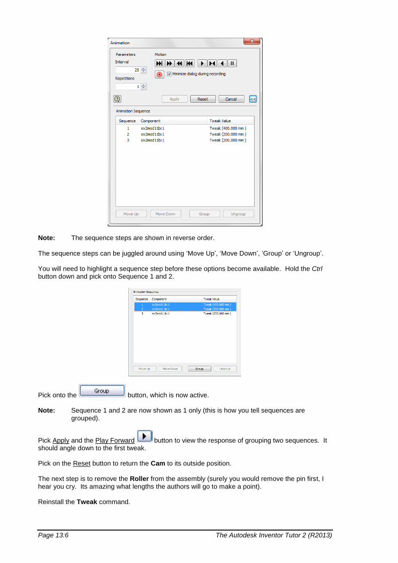
Note: The sequence steps are shown in reverse order. The sequence steps can be juggled around using ‘Move Up’, ‘Move Down’, ‘Group’ or ‘Ungroup’. You will need to highlight a sequence step before these options become available. Hold the Ctrl button down and pick onto Sequence 1 and 2.
Pick onto the button, which is now active. Note: Sequence 1 and 2 are now shown as 1 only (this is how you tell sequences are
grouped).
Pick Apply and the Play Forward button to view the response of grouping two sequences. It should angle down to the first tweak. Pick on the Reset button to return the Cam to its outside position. The next step is to remove the Roller from the assembly (surely you would remove the pin first, I hear you cry. Its amazing what lengths the authors will go to make a point). Reinstall the Tweak command.

The Autodesk Inventor Tutor 2 (R2013) Page 13:7
Pick onto the button (if not pre-selected) and place the 3D direction arrows on the Roller Bracket (or the general area) as shown.
In the Create Tweak sector the is automatically selected. Pick onto the Roller (perimeter shown blue). Note: The orientation of the UCS axis will determine the Axis and Distance values used in the
Transformations sector. The orientation could be in any direction and then the appropriate Axis and Distance values (+ or -) would be based on the UCS.
The direction to move is along the X axis. Pick on the X button in the Transformations sector. Type in, a travel distance of ‘-45 mm’ (down or –X value) in the Tweak distance edit box
(Transformations sector), followed by picking the button.
Pick onto the Z button and type in a travel distance of ‘-200’.
Pick onto the button to complete the Roller movement. Return to the Direction button once again and place in the same orientation as before. Use the Components button to select the Pin. Now move the Pin along the Z axis -200mm. It should look like this.

Page 13:8 The Autodesk Inventor Tutor 2 (R2013)
Finally, the Roller Bracket needs exploding. In this case both linear and rotational movement is required. Pick the Direction button and reposition the 3D direction arrows on the centre of the hole in the base, as shown. Up to this point it has not been important to position the 3D direction arrows exactly on the moving (tweaked) part, but in this case the roller bracket has to rotate primarily in the base hole before removal.
Pick onto the Roller Bracket to select.
Pick on Z button and radio button Rotational. Notice the rotational directions have been added to the 3D direction arrows.
Type in the Tweak Angle edit box ‘90’ and pick the .

The Autodesk Inventor Tutor 2 (R2013) Page 13:9
Now pick on the Linear radio button and move the Roller Bracket down linearly Z = ‘-43’ and X = ‘-200’. It should look like this.
Close the Tweak Component dialogue box and once again install the Animate… command.
Look at the sequence for your animation by selecting .

Page 13:10 The Autodesk Inventor Tutor 2 (R2013)
The self made error of animating the Roller, before extracted the Pin, can now be corrected. Highlight Sequence 5 and 6 (by picking and holding down the Ctrl key). Pick on the Group button. Re select the grouped roller and pick on the Move up button. The animation sequence should be updated. It should look like this:
Pick on the button to close the Animation Sequence sector and pick onto the button.

The Autodesk Inventor Tutor 2 (R2013) Page 13:11
Pick the Play Forward button to view the modified sequences. You will notice, the correct sequences take place, but the roller moves diagonally rather than in two
steps as before. Pick on the button followed by selecting , highlighting
Sequence 4 and picking on the .
Pick onto the button and try the Play Forward button again. If the tweak trails (shown in blue) are required to be removed from the animation, it can be achieved through the:
1. Model Browser (when the animation has been completed). OR
2. The Tweak Component dialogue box (at the start of the animation).
Consider the Model Browser only. Open all the families in the browser.
Hold the Ctrl key down and select all the Tweaks and then pick the mouse RH button and deselect ‘Visibility’. The trails are now removed. Note: The tweak trails can also be modified by:
1. Selecting a ‘Tweak’ in the browser, an edit box appears at the bottom.
2. Selecting in the Tweak Component dialogue box (see Task below). Finally, a word about the Parameters sector in the Animation dialogue box:
The number of intervals (frames) in a tweak. The lower the number the faster the execution
The number of repetitions for the animation

Page 13:12 The Autodesk Inventor Tutor 2 (R2013)
If a film is required of the finished animation, the button in the Animation dialogue box should be selected. A Save As dialogue box will be displayed.
Depending on your choice of film (.wmv or .avi), you would Save with a new File name (not required at this time). More on films, etc. in Module14. Save As the final tweak animation as xx2mod13an. Pick Yes to All button when the Save dialogue box is displayed.
TASKS
1. You would have noticed that the Roller and Pins trail initially goes through the base
Goalpost.
Correct this error by assembling the Roller Bracket, Pin and Roller away from the base and then move them together into the Goalpost, followed by the Flat Cam.
2. In this Module we have only considered manual single tweaks. There is an Automatic Tweak option for presentation views. The Automatic Tweak option can be activated when the assembly is first loaded or when the presentation is being constructed (use Model browser to select the assembly. iam file and then pick the mouse RH button to view the options). Start a New presentation file and load the Flat Cam and Follower assembly once again and install the Automatic Tweak option. Save as the automatic tweaked assembly xx2m13task.