mod-shock system - geohart brochure feb 2011.pdf · the mod-shock tests system is a complex ... tie...
TRANSCRIPT

GEOHART CONSULTANTS Pty Ltd ABN: 28 979 550 809 / ACN: 137 859 128
http//www.geohartconsultants.com.au 5A Hartnett Close, Mulgrave, Vic 3170, Australia
O (+61) (3) 8562 2222 F (+61) (3) 9923 2746
Mod-Shock System
Non-Destructive
Rock Reinforcement
Testing

1 BACKGROUND INFORMATION
The traditional pull out tests currently used for rock reinforcement testing is not
considered an effective tool for the detection of compromised rockbolt systems used for
ground control in underground mining and civil construction industries. Where it is still
acknowledged that the pull out test has still an important role to play in determining
critical bond lengths for static and quasi static ground support designs, it does not
provide an underground operation with any reassurance regarding its bolt’s integrity,
which could have been compromised during installation or affected by in-situ aggressive
conditions.
Figure 1 – Recent (October 2009) pull testing on resin bolting for Modshock
elastic load vs displacement calibration purpose.
Non-Destructive rock reinforcement integrity testing conducted at three Australian
Mines (i.e. Western Australia, Queensland and Victoria) have shown that there is
potential to optimise this testing method. More than 150 bolts comprising 40 rebar type
bolts, 100 Cable Bolts and 12 Splitsets have been tested to date. The non-destructive
rock reinforcement integrity testing analysis is conducted using a complex “Stress Wave
Analysis“ package based on the processing of clear seismic signals imparted into the
rock reinforcement element that is being tested. The seismic signals are processed by

“Fourier Transform” into various criteria which can be used to produce models of the
element such as mechanical admittance, frequency spectra and velocity which are all
being used in the final modelling of the rock reinforcement element under analysis. The
non-destructive integrity testing of rock reinforcement at these mines indicated that
there is opportunity to further investigate the potential in effectively managing the risk of
fall of ground incidents at underground mine and construction sites.
The Mod-Shock tests system is a complex “ Stress Wave Analysis “ package based on the processing of clear seismic signals imparted into which ever element (i.e. rock bolt) is being tested. The seismic signals are processed by “Fourier Transform” into various criteria which can be used to produce models of the element such as “Mechanical Admittance, frequency spectra, velocity” and other less important aspects, all being used in the final modeling of the element under analysis. The Mod-Shock system is a development of Mr. John Higgs and Mr. David Tongue, amongst others who have developed the system to test a multitude of differing elements, including piles, columns, floors, steel poles, tie rods, ground anchors and other elements associated with Civil Engineering. The development started in the late 80’s and has been used for the correct assessment, which now exceeds well over 1,000,000 tests on a large variety of elements, over the last 20+ years. As with anything new the Mod-Shock has been subjected to numerous trials, peer reviews and scrutiny by both academia and the commercial consultants and contractors within the civil engineering industries. A large amount of the background physics can be attributed to two eminent professors in the field of research in “Davis and Dunn” and their work with the French research department in the early 80’s for “Central Bureau de Engineering Travaux Public (CBETP), with John Higgs being fortunate to be one of their understudy disciples, carrying on to further develop their early work into the Mod-Shock.
1.1 The Mod-Shock System for Mining
Integrity Testing (i.e. developers of the system) has for over 15 years carried out testing of long length steel rods, either as strand or solid steel bars. Possibly the most notable project being for BHP, when they owned the Whyalla steel works where they tested the tie rods holding back the crucial steel pile wall of the coal handling jetty. The rods were tested and not only were the defective rods identified but it was indicated at what point the rods had lost a large cross section. This was located at a point where the rods came close to the base of the coal handling pit and water was seeping onto the rods causing corrosion. Thus a large successful background in the testing of steel embedded elements, generally with the lengths in excess of 5 meters. Presently Freyssinet have tested rock bolts and anchors on five projects and at this time seem to be having a good deal of success with the results. The following is an important reminder:

This test is a “QA” geotechnical risk management tool / test which eliminates good bolts and identifies bolts that may have some deficiency, be it in low load capabilities or loss of cross section of the bolt (e.g. bolt diameter decrease due to corrosion), as the test is cost effective and can test a large population of bolts in a short period of time.
2 THE TEST
There are four components to the system:
Figure 2a – Annotation of the Modshock system.
1. A Panasonic Toughbook Note book - this is used to collect data and providing power via a USB cable for the…..
2. Analogue/Digital Converter - this converts the signal from the transducer into a digital format. The converter is hardwired to the…
3. Transducer – which is held at the end of bolt (i.e. collar of hole) during the test. A signal / pulse is obtained, which is generated by…..
Figure 2b – Schematic of transducer position during test.
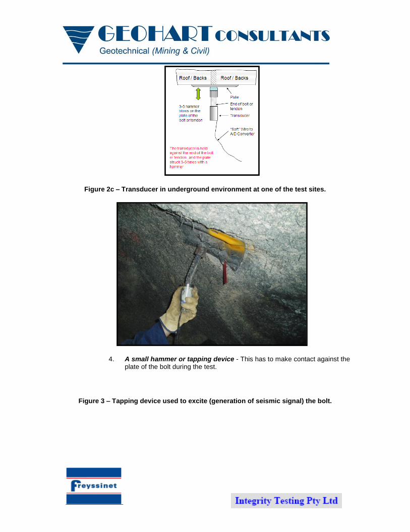
Figure 2c – Transducer in underground environment at one of the test sites.
4. A small hammer or tapping device - This has to make contact against the plate of the bolt during the test.
Figure 3 – Tapping device used to excite (generation of seismic signal) the bolt.

• The transducer is held against the bottom of the test bolt, the program informed that a test is about to take place by clicking an icon
• The plate is struck 3-5 times with a hammer • If satisfactory signal is received by the computer-move to next bolt • Otherwise re-test, may take several attempts to get a good signal.
Figure 4 – Two graphs showing the difference between a good signal obtained
and an unacceptable signal.
3 ANALYSIS AND REPORTING
The operator in the field can at the time of testing identify which bolts are serviceable and then concentrate on the bolts that have anomalies. For the bolts with anomalies a print out of the test can be obtained after the analysis has been carried out. This print out provides a 2D model of the bolt under test and a number of criteria such as the “Stiffness” of the bolt is shown, which is compared to two models of fixity of the bolt.
The information is available for further investigation into why the bolt had an anomaly, such as a “low Stiffness” result or large loss of section on the 2D model. One of the vital pieces of information obtained from the Mod-Shock test is the “Head Stiffness” as this is the basis of all the load predictions and it also indicates the serviceability of the total bolt system. The head stiffness is the “E” prime of the bolt, measured as a direct measurement of the first part of the “mechanical admittance plot”, and is similar to a load/displacement graph for a pull out test. The stiffness calculation is not always an accurate result as we would desire and as such is only used to determine the overall assessment of the bolt. The “bolt head stiffness (tonnes/mm)” is compared to the two model stiffness values “E” min and “E” max. “E” min is a bolt model with the bolt pinned at its toe (end anchored) but with no clamping (no resin or grouting) along its length. “E” max is a bolt model with an infinite rigid base and “clamped” (full column grouted / resin) along its length. These models are based on the work carried out by Davis & Dunn and they summed up the theory with descriptions as follows:-
For a serviceable bolt, with good anchorage at the toe and with good encapsulation into good rock, the stiffness should lie between the “E” max and “E” min values.
A serviceable bolt can also have a stiffness value slightly below the “E” min value if it has good anchorage, but either the encapsulation of the length of the bolt is due to poor grouting or incorrectly mixed resin, or poor load transfer between the rock and the bolt.
With the same model in mind a bolt with point anchorage would have a stiffness value well below the “ E “ min, but if this is the design, then this would still be serviceable.
Non serviceable bolts would have a stiffness value well below the “E” min values, such as less than 70% of the “E” min value. This indicates either poor anchorage or large loss of section and no load transfer along the length of the bolt.
Non serviceable bolts can also have what we describe as overstressed areas in the system, where the Stiffness is far in excess of the “E” max value. What occurs in this scenario is that due to some defect in the bolt grout/resin system a part of the system is being overstressed. An example of this would be that corrosion of the bolt has occurred at the interface of the grout and the bolt. This reduced section of the bolt is taking more load than it was designed for and as such is overstressed and at risk of failure.
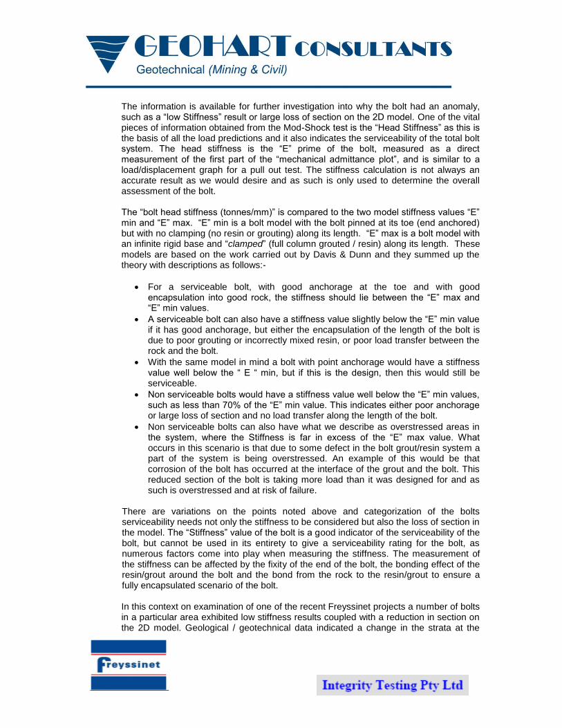
There are variations on the points noted above and categorization of the bolts serviceability needs not only the stiffness to be considered but also the loss of section in the model. The “Stiffness” value of the bolt is a good indicator of the serviceability of the bolt, but cannot be used in its entirety to give a serviceability rating for the bolt, as numerous factors come into play when measuring the stiffness. The measurement of the stiffness can be affected by the fixity of the end of the bolt, the bonding effect of the resin/grout around the bolt and the bond from the rock to the resin/grout to ensure a fully encapsulated scenario of the bolt. In this context on examination of one of the recent Freyssinet projects a number of bolts in a particular area exhibited low stiffness results coupled with a reduction in section on the 2D model. Geological / geotechnical data indicated a change in the strata at the

location on the model where a loss of section appeared to be apparent and in the context of the serviceability, the bolt was under some strain due to displacement on this fault, but still classified as a serviceable bolt. Figures 5 to 7 below shows typical plots of tests following the analysis.
Figure 5 – 2D Plot of a Calibrated Bolt.
Figure 6a – Calibration Test Set-up Cable Bolt – e.g. Poor Cable Bolt Grout Installation.
Figure 6b – Signal.

Figure 6c – 2D Mechanical Admittance Plot.
Figure 7a – Calibration Test Set-up Resin Bolts.

Figure 7b - 2D Mechanical Admittance Plot for Test 22 – e.g. Good Bolt.
Figure 7c - 2D Mechanical Admittance Plot for Test 2 – e.g. Poor resin encapsulation.
Figure 8a – Calibration Test Set-up Friction Bolt.

Figure 8b - 2D Mechanical Admittance Plot for Test 30 – e.g. Typical splitset / friction bolt.
Figure 8c - 2D Mechanical Admittance Plot for Test 34 – e.g. Splitset / friction bolt failed.
For the present moment a simple classification system have been adopted which are provided below in Table 1 below.
Table 1: Bolt serviceability classification system.
Category 1. A perfect bolt in perfect rock conditions – in our opinion
this will rarely occur
Category 2.
A bolt which we consider is serviceable in that it has
good anchorage, good load transfer along the length of
the bolt and reasonable rock/grout/resin contact.
Category 3. A bolt that has some deficiencies in reduced anchor
strength, poor grout/resin/rock contact or loss of bolt

section. The remarks section will identify the possible
source of the deficiency.
Category 4.
A bolt that has either failed, is loose or at a point
where additional load on the bolt could lead to
failure, or a loss of bolt section which is critical.
The basis of the above criteria is not new, but from proven results from over coring at previous rock bolt and tie rod projects, though the categories are subjective the more information is obtained from the site trials the more confidence can be instilled in the testing procedure and results.
4 LIST OF MINES WHERE TESTS HAVE BEEN CONDUCTED
Sunrise Dam – Gold Mine – Anglogold Ashanti
Fosterville Gold Mine – Northgate Minerals
Xstrata Zinc – Mt. Isa
Springvale Colliery
North Goonyella
Mandalong Coal
Broadmeadows
Grasstree West
Tahmoor
5 CLIENT FEEDBACK
Below are a few questions from a client following a recent test and our response.
How does category rating compare to visual assessment – any relation for those units
under stress or with reduced stiffness? I assume that this would be the case as it was all
units that concerned you.
Good question as we have discuss this in some length….It is very important we categorized the
bolt/rock reinforcement as per information we obtain through the testing – as it is an objective test
and describing the integrity of the intact bolt compare to visual observation which only describe
the appearance…There is a few bolts where we visually detected that the plate was bend and
were described as being overstressed…..

Can the units that show load/stiffness issues be related to a certain failure mechanism in
the rockmass (local structure, blasting, induced stress), or could the load state be due to
installation in certain cases?
At this stage none of the information obtained through testing gave us any indication of bolt failure
rather issues related to inefficient installation or resin/grout affected by an aggressive
environment.
Are we planning overcoring to confirm these results or is the technique a proven practice
that we can reference form another source?
At this stage we have not recommended overcoring as a means to confirm information obtained
from the testing. The emphasis was placed on calibration bolts to be tested in parallel with the
test bolts. However if we look at this in terms of R&D any additional work that is conducted to
confirm the status / integrity of the rock reinforcement system is welcomed.
What is the “ratio” of bolts taking load (tested) to those not?
- 17% of all bolts tested showed signs of being overstressed - 27% of Posimix bolts tested showed signs of being overstressed (all in **@@
intersection area) - 12% of cable bolts tested showed signs of being overstressed (one in **@@ intersection
area and two in @@** area)
Will these tests help decide whether the ground support is adequate, over supporting or
need to be relooked?
There is no doubt in our (GEOHART Consultants) mind that, that is the end objective for these
tests. With more testing and information available to us the current categories could be more
refined, but it lies with the scope of the work and what the requirement of the scope of works is.
Currently a typical scope will suggest that certain tests will be conducted and that results will be
provided. Comments about the potential problems/integrity deficiency at hand e.g. possible bolt
failure, poor load transfer (resin to bolt, resin to rock etc) will also be made.
One of the opportunities or problems we see for engineers is to confirm the design
specification….e.g. 2.4m long resin anchor, where 2.3m length is the anchor length inclusive of a
typical 350mm critical bond length….see Figure 8 below - the critical length as we know should
be at the end of the bolt to act as an anchor to support a theoretical block of rock to the perimeter
of the excavation….

Figure 8 – Plot of possible integrity problems we experience with bolts.
For bolt failure (reinforcement system detached) - in all three cases the bolt would be
unserviceable
For poor load transfer conditions as seen in the three cases in the above figure the
following is seen as a potential problem:
1. For this bolt / support systems it would potentially be a problem where the ground support system does not meet the design specification which is outlined in the Ground Control Management Plan – e.g. critical bond length 300mm and designed bolt length 2.3m inclusive of CBL - bolt unserviceable.
2. For this bolt / support systems it would potentially be a problem for quality of resin/grouting also outlined in the Ground Control Management Plan – bolt would be serviceable
3. For this bolt / support systems it would potentially be a problem for quality of resin/grouting also outlined in the Ground Control Management Plan – bolt would potentially be un-serviceable if plates are not secured.