modal analysis of high pressure fuel injection pipe for a ...the study uses ansys workbench-12...
TRANSCRIPT
International Journal for Research in Engineering Application & Management (IJREAM)
ISSN : 2454-9150 Special Issue - AMET-2018
60| AMET_0015 @ MIT College of Engineering, Pune, Vol.04, Special Issue AMET-2018 DOI : 10.18231/2454-9150.2018.1400
Modal Analysis of High Pressure Fuel Injection Pipe for a DV-10 V
Diesel Engine
Prof. Chetan K.Patil1,Rajesh Askhedkar2 S.B.Girase3, G.D.Shrigandhi4
Savitribai Phule Pune University, MITCOE Pune.1, [email protected] Kirloskar oil Engines Ltd. [email protected] Savitribai Phule Pune University, MITCOE Pune.2, [email protected] Savitribai Phule Pune University, MITCOE Pune [email protected]
Abstract
Modal analysis is a method to describe a structure in terms of its natural characteristics which are the frequency, damping and mode shapes its dynamic properties. It is a process of determining unwanted vibratory behavior pattern in an engineering component which is subjected to loading conditions. Modal analysis helps in not only determining and rectifying the problems but also assist in enhancing the product design aspects to eliminate the problems from the roots.
The study uses ANSYS WORKBENCH-12 software to derive the finite element model of the fuel pipe. Based on this model, the clamp locations are found and fuel injection pipe assembly is produced. In this report we find a suitable methodology to get more effective vibration control of fuel pipe with minimum input. The methodology adopted here gives the reduction of the engine induced vibration by giving proper clamp locations and increasing suitable number of clamps.
Keywords: FEM, FFT, Fuel injection pipe, Frequency, Modal analysis.
1. Introduction
In today’s world competition, in the engine scenario,
the safety against failure offered by the diesel engine plays an important role. The safety of engine is significantly affected by the vibrations and noise which is experienced by the user during its operating conditions. These vibrations are generally caused by the mass unbalance, misalignment and are transmitted to the fuel injection pipe. In a diesel engine, fuel pipe vibration varies largely according to the suitable number of clamps and there locations.
The fuel injection pipe is use to carry the high
pressure fuel up to1800 bar from fuel pump to fuel injector of an engine. There are different causes of pipe failure such as excessive vibration, improper stress reliving, and hardness of pipe & loosening of pipe joint. But many times pipe is fail due to excessive vibration.
Modal analysis gives the modal parameters
especially natural frequency mode shapes & damping values of the structure, which would define the dynamic behavior of structure.
This paper describes the methodology to reduce the fuel pipe vibrations which are induced by engine. The method involves the Finite Element Modal analysis and structural modification which reduce the fuel pipe vibration levels induced from the engine excitations with the help of Finite Element technique. This study focuses on the modal behavior of fuel injection pipe.
2. Evaluation Of The Severity Of Piping Vibration
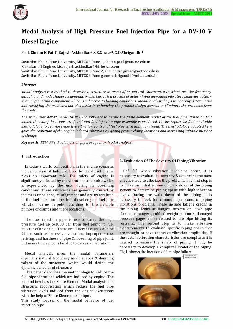
Ref. [4] when vibration problems occur, it is
necessary to evaluate its severity & determine the most effective way to alleviate the problems. The first step is to make an initial survey or walk down of the piping system to determine piping spans with high vibration levels. During the walk down of the piping, it is necessary to look for common symptoms of piping vibrations problems. These include fatigue cracks in the piping, leaks at flanges, broken or loose pipe clamps or hangers, rubbed weight supports, damaged pressure gages, noise related to the pipe hitting its restraint. The second step is to make vibration measurements to evaluate specific piping spans that are thought to have excessive vibration amplitudes. If the system vibration characteristics are complex & it is desired to ensure the safety of piping, it may be necessary to develop a computer model of the piping. Fig.1. shows the location of fuel pipe failure.
International Journal for Research in Engineering Application & Management (IJREAM)
ISSN : 2454-9150 Special Issue - AMET-2018
61| AMET_0015 @ MIT College of Engineering, Pune, Vol.04, Special Issue AMET-2018 DOI : 10.18231/2454-9150.2018.1400
Fig. 1. Failure of high pressure fuel injection pipe
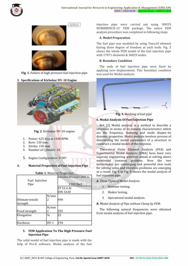
3. Specifications of Kirloskar DV-10 Engine
Fig. 2. Kirloskar DV-10 engine
1. Power: 625 Kva at 1500 RPM. 2. Bore: 130 mm. 3. Stroke: 150 mm. 4. Number of Cylinder: 10.
5. Engine Configuration: V-90o. 4. Material Properties of Fuel Injection Pipe
Table 1. Material Properties Injection Pressure (800 to
Fuel Injection Pipe 1300 Bar)
ST 52.4 Al DIN 1630
Ultimate tensile N/mm2 490
strength
Proof strength N/mm2 355
Elongation % 22
Hardness HV-1 194
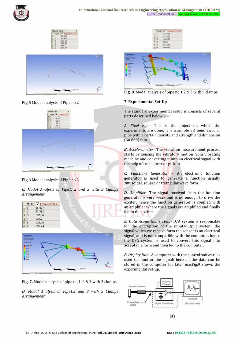
5. FEM Application To The High Pressure Fuel
Injection Pipe
The solid model of fuel injection pipe is made with the help of Pro-E software. Modal analysis of the fuel
injection pipe were carried out using ‘ANSYS WORKBENCH-12’ FEM package. The entire FEM analysis procedure was completed in following steps.
A. Model Preparation
The fuel pipe was modeled by using Tetra10 element having three degree of freedom at each node. Fig. 3 shows the whole FEM model of the fuel injection pipe with 17071 elements & 30829 nodes.
B. Boundary Condition
The ends of fuel injection pipe were fixed by applying zero displacement. This boundary condition was used for Modal analysis.
Fig. 3. Meshing of fuel pipe
6. Modal Analysis Of Fuel Injection Pipe
Ref. [2] Modal analysis is a method to describe a structure in terms of its natural characteristics which are the frequency, damping and mode shapes–its dynamic properties. Modal analysis involves process of determining the modal parameters of a structure to construct a modal model of the response.
Theoretical Finite Element Analysis (FEA) and Experimental Modal Analysis (EMA) have been very separate engineering activities aimed at solving above mentioned common problem. Now the two technologies are converging and powerful new tools for solving noise and vibration problems are emerging as a result. Fig. 4 to Fig. 8 shows the modal analysis of fuel injection pipe.
A. Three Types of Modal Analysis:
1. Hammer testing.
2. Shaker testing.
3. Operational modal analysis.
B. Modal Analysis of Pipe without Clamp by FEM:
The following natural frequencies were obtained from modal analysis of fuel injection pipe.
International Journal for Research in Engineering Application & Management (IJREAM)
ISSN : 2454-9150 Special Issue - AMET-2018
62| AMET_0015 @ MIT College of Engineering, Pune, Vol.04, Special Issue AMET-2018 DOI : 10.18231/2454-9150.2018.1400
Fig.5 Modal analysis of Pipe no.2
Fig.6 Modal analysis of Pipe no.3 C. Modal Analysis of Pipe1, 2 and 3 with 3 Clamps Arrangement:
Fig. 7. Modal analysis of pipe no.1, 2 & 3 with 3 clamps D. Modal Analysis of Pipe1,2 and 3 with 5 Clamps Arrangement:
Fig. 8. Modal analysis of pipe no.1,2 & 3 with 5 clamps 7. Experimental Set-Up The standard experimental setup is consists of several parts described below:- A. Steel Pipe- This is the object on which the experiments are done. It is a simple 3D bend circular pipe with a certain density and strength and dimension (6× 860) mm. B. Accelerometer- The vibration measurement process starts by sensing the vibratory motion from vibrating machine and converting it into an electrical signal with the help of transducer or pickup. C. Functions Generator – An electronic function generator is used to generate a function usually sinusoidal, square or triangular wave form. D. Amplifier- The signal received from the function generator is very weak and is no enough to drive the exciter, hence the function generator is coupled with an amplifier where the signals are amplified and finally fed to the exciter E. Data Acquisition system- D/A system is responsible for the encryption of the input/output system, the signal which we receive form the sensor is an electrical signal, and is not compatible with the computer, hence the D/A system is used to convert this signal into acceptable form and then fed to the computer. F. Display Unit- A computer with the control software is used to monitor the signal; here all the data can be stored in the computer for later use.Fig.9 shows the experimental set-up.
(a)
International Journal for Research in Engineering Application & Management (IJREAM)
ISSN : 2454-9150 Special Issue - AMET-2018
63| AMET_0015 @ MIT College of Engineering, Pune, Vol.04, Special Issue AMET-2018 DOI : 10.18231/2454-9150.2018.1400
(b)
Fig. 9. Experimental set-up 8. Experimental Results
We have found the frequency of high pressure fuel pipe by using FFT Analyzer. The results are taken on DV-10 engine and it is shown in table III. For measurement modal hammer, uniaxial accelerometer, triaxial accelerometer & pulse system is used. During measurement, modal hammer is connected to pulse system through connecting cable. A more convenient and economical excitation method is a hammer fitted with a high-quality piezoelectric force transducer.
The uniaxial & triaxial accelerometer is used for measuring the vibration amplitude & frequency spectrum. The accelerometer is connected to pulse system by means of cable. Fig. 10 shows the vibration measurement process
Fig. 10. Basic features of vibration measurement process
Table 2. Frequency Results At Pipe 1, 2 And 3 With 3 Clamps Arrangement
Mode No. Frequency
(Hz)
1 48
2 64
3 93
4 125
5 141
6 155
Table 2 shows the frequency of fuel injection pipe for
corresponding mode shapes. These results are taken on the fuel injection pipe no. 1,2 and 3 with 3 clamp arrangement with the help of modal hammer. 9. Experimental Equipment
Different equipments are used to measure the frequency, vibration velocity & amplitude of the high pressure pipe such as, A. Accelerometer (Brüel & Kjær): Uniaxial accelerometer is intended for measurement of vibration only in 1 axis. Triaxial accelerometer is intended for simultaneous measurement of vibration in 3 perpendicular axis. Fig. 11 shows the Uniaxial accelerometer
Fig. 11. Uniaxial accelerometer B.Modal hammer (Brüel & Kjær, 2302-10):
A more convenient and economical excitation method is a hammer fitted with a high-quality piezoelectric force transducer. The piezoelectric transducer which produces input signal proportional to their deformation. In applications where a high crest factor and a limited ability to shape the input force spectrum are of no concern, impact hammer testing is an ideal source of excitation. Fig. 12 shows the Modal hammer.
Fig. 12. Modal hammer
International Journal for Research in Engineering Application & Management (IJREAM)
ISSN : 2454-9150 Special Issue - AMET-2018
64| AMET_0015 @ MIT College of Engineering, Pune, Vol.04, Special Issue AMET-2018 DOI : 10.18231/2454-9150.2018.1400
C. PULSE Labshop version 15.10 (Brüel & Kjær):
Pulse Labshop is the fast Fourier transform analyzer which receives digital signal from the hammer and the accelerometer and converts it. PULSE Labshop version 15.10 is shown in fig.13.The various parameters check with the Pulse Labshop software are: 1. Frequency Response Function. 2. Coherence. 3.Time weighting signals
Fig. 13. Pulse labshop system D. FFT Analyzer (Brüel & Kjær):
The FFT analyzer and the accelerometer are the interface to convert the time domain response to frequency domain. Hence the frequency response spectrum (response, force) is obtained. E. Display unit (Dell laptop):
This is mainly in the form of PC (Laptop) when the excitation occurs to the signals transferred to the portable PULSE and after conversion comes in graphical form through the software. Generally, the data includes graphs of force vs. time, frequency vs. time.
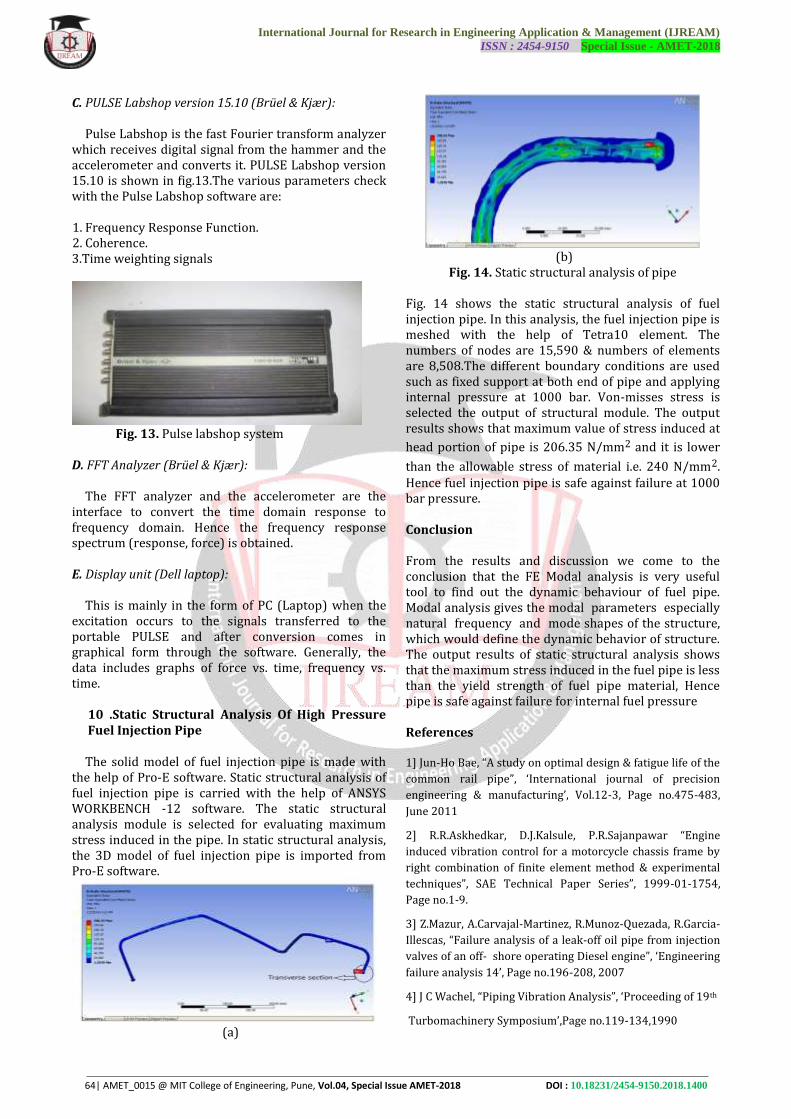
10 .Static Structural Analysis Of High Pressure Fuel Injection Pipe
The solid model of fuel injection pipe is made with
the help of Pro-E software. Static structural analysis of fuel injection pipe is carried with the help of ANSYS WORKBENCH -12 software. The static structural analysis module is selected for evaluating maximum stress induced in the pipe. In static structural analysis, the 3D model of fuel injection pipe is imported from Pro-E software.
(a)
(b)
Fig. 14. Static structural analysis of pipe
Fig. 14 shows the static structural analysis of fuel injection pipe. In this analysis, the fuel injection pipe is meshed with the help of Tetra10 element. The numbers of nodes are 15,590 & numbers of elements are 8,508.The different boundary conditions are used such as fixed support at both end of pipe and applying internal pressure at 1000 bar. Von-misses stress is selected the output of structural module. The output results shows that maximum value of stress induced at
head portion of pipe is 206.35 N/mm2 and it is lower
than the allowable stress of material i.e. 240 N/mm2. Hence fuel injection pipe is safe against failure at 1000 bar pressure. Conclusion From the results and discussion we come to the conclusion that the FE Modal analysis is very useful tool to find out the dynamic behaviour of fuel pipe. Modal analysis gives the modal parameters especially natural frequency and mode shapes of the structure, which would define the dynamic behavior of structure. The output results of static structural analysis shows that the maximum stress induced in the fuel pipe is less than the yield strength of fuel pipe material, Hence pipe is safe against failure for internal fuel pressure References 1] Jun-Ho Bae, “A study on optimal design & fatigue life of the
common rail pipe”, ‘International journal of precision
engineering & manufacturing’, Vol.12-3, Page no.475-483,
June 2011
2] R.R.Askhedkar, D.J.Kalsule, P.R.Sajanpawar “Engine
induced vibration control for a motorcycle chassis frame by
right combination of finite element method & experimental
techniques”, SAE Technical Paper Series”, 1999-01-1754,
Page no.1-9.
3] Z.Mazur, A.Carvajal-Martinez, R.Munoz-Quezada, R.Garcia-
Illescas, “Failure analysis of a leak-off oil pipe from injection
valves of an off- shore operating Diesel engine”, ‘Engineering
failure analysis 14’, Page no.196-208, 2007
4] J C Wachel, “Piping Vibration Analysis”, ‘Proceeding of 19th
Turbomachinery Symposium’,Page no.119-134,1990