modal analysis of oroville dam - ed wilson analysis of oroville dam.pdf · model analysis of...
TRANSCRIPT

Model Analysis of Oroville Dam The Dam that was never built by Ed Wilson Draft Dated July 2, 2014 In 1957 the construction of the Oroville Dam was a major project for the State of California Department of Water Resources. It is still the highest dam in the United States. They were considering five different designs for the 730 feet high dam with the water surface elevation of 900 feet above mean sea level. They were a concrete gravity, buttress, multiple arches, arch buttress and a rock-fill embankment dam as shown below in Figure 1.
The arch buttress dam was a new type of dam structure and required a three-dimensional analysis. Therefore, the board of consultants recommended a model study of the dam, as shown in Figure 2, be conducted.

Contract with the University of California and the State The Engineering Materials Laboratory, EML, at Berkeley was constructed to conduct a significant amount of the material testing for Hoover Dam in 1931 under the direction of Professor R. E. Davis. In addition to a chemical laboratory, a 4 million pound testing machine and a large number of temperature and humidity control rooms, EML was in a unique position to assist the State with the design and construction of Oroville Dam. Professor Howard Eberhart had joined the faculty in 1936 and had a proven record of research in many different areas of engineering. Professor Jerome Raphael joined the faculty in 1953 as an Associate Professor with over 10 years experience with the Bureau of Reclamation on the design and construction of concrete dams. The contract with the State was for several different types of testing. Professor Eberhart was head of all investigations and would personally direct the photo elasticity analysis of the largest underground powerhouse ever constructed. Professor Pirtz would conduct the adiabatic temperature properties and other material properties of the concrete cylinders 20 inches in diameter and 40 inches height – which would be supplied by the State for testing at the University. Professor Raphael was primarily responsible for the creation and testing of the model of the arch/buttress dam. I was offered a position on the Oroville Dam project by Professor Eberhart after I wrote to him from Korea informing him of my plans to attend graduate school in January 1957. During next the three years I worked on all four areas of the project including the 4 million pound testing machine to load to failure the 20 by 40 inch cylinders. At the start of the project Professor Raphael hired a full time engineer, Stuart Bartholomew, with several years experience in the design and construction of concrete dams in many areas of the world. As the project engineer,

his function was to organize the fabrication of the Oroville model and to supervise six or seven individuals, including me. About a year before the completion of the model studies the Board of Consultants made the decision to recommend the rock fill design due to the predicted low cost by using the large amount of hard rock, very near the dam site, produced by dredger mining of gold prior to 1900. However, it was decided by the State they would continue funding the project in order to develop new experimental methods for creating, loading and testing of the Oroville model that would apply to subsequent dam model studies.
Evaluation of Material Properties The Oroville Dam contract was signed on approximately April 1, 1957 and I immediately started to work directly for Professor Raphael 20 hours a week. My initial assignment was to determine the properties of the plaster-celite material used to construct the model and foundation. Celite is a light-weight marine deposit that did not chemically interact with the plaster or water. Due to his previous experience with the design of concrete mixes (which continue to get stiffer with time), Professor Raphael proposed an elaborate testing program which I worked on for over six months. This research was reported in a 60 page Appendix to the final report which can be read at
http://nisee.berkeley.edu/documents/SEMM/SEMM-60-06.pdf After we started working with large pours, we finally discovered all the chemical reaction occurred within one hour after it was poured. The model material would then have constant mechanical properties when all the water was removed. The only restriction was the drying temperature could not exceed 130 degrees Fahrenheit to avoid the reversal of the water-plaster bonding. However, this information was not included in the final report.
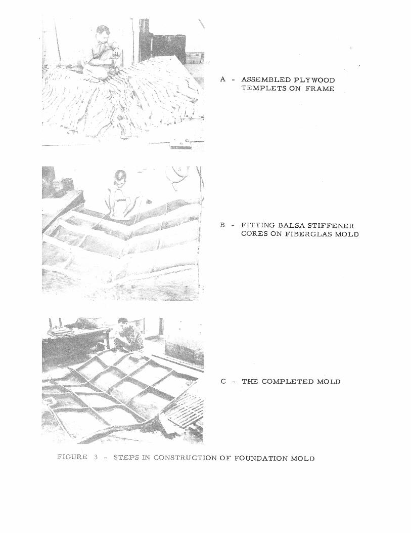
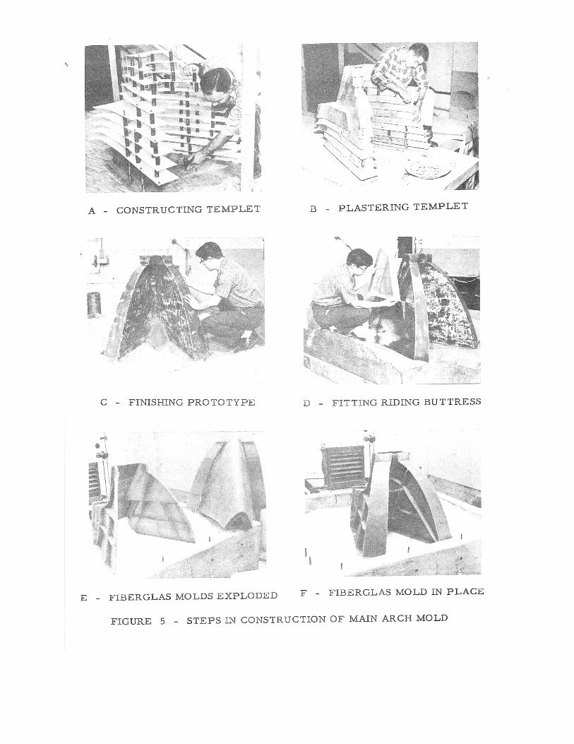
Construction of the Model An examination of Figures 3, 4, and 5 indicates the complexity which was used to create the forms for the foundation, plug, main arch and buttresses for the model. It was very time consuming and labor intensive. In addition, the different components had to be constructed in sequence. As I recall, this phase of the project took a full year.

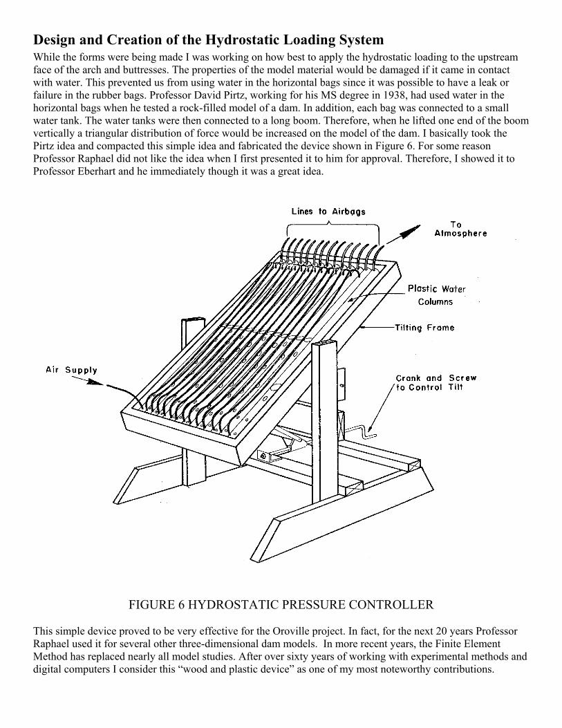
Design and Creation of the Hydrostatic Loading System While the forms were being made I was working on how best to apply the hydrostatic loading to the upstream face of the arch and buttresses. The properties of the model material would be damaged if it came in contact with water. This prevented us from using water in the horizontal bags since it was possible to have a leak or failure in the rubber bags. Professor David Pirtz, working for his MS degree in 1938, had used water in the horizontal bags when he tested a rock-filled model of a dam. In addition, each bag was connected to a small water tank. The water tanks were then connected to a long boom. Therefore, when he lifted one end of the boom vertically a triangular distribution of force would be increased on the model of the dam. I basically took the Pirtz idea and compacted this simple idea and fabricated the device shown in Figure 6. For some reason Professor Raphael did not like the idea when I first presented it to him for approval. Therefore, I showed it to Professor Eberhart and he immediately though it was a great idea.
FIGURE 6 HYDROSTATIC PRESSURE CONTROLLER This simple device proved to be very effective for the Oroville project. In fact, for the next 20 years Professor Raphael used it for several other three-dimensional dam models. In more recent years, the Finite Element Method has replaced nearly all model studies. After over sixty years of working with experimental methods and digital computers I consider this “wood and plastic device” as one of my most noteworthy contributions.
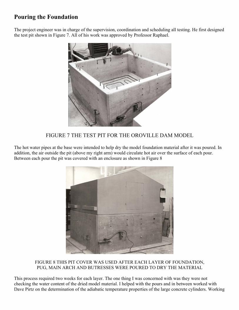
Pouring the Foundation The project engineer was in charge of the supervision, coordination and scheduling all testing. He first designed the test pit shown in Figure 7. All of his work was approved by Professor Raphael.
FIGURE 7 THE TEST PIT FOR THE OROVILLE DAM MODEL
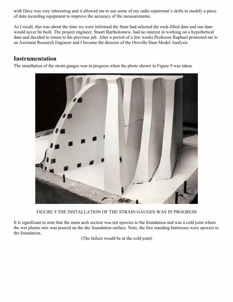
The hot water pipes at the base were intended to help dry the model foundation material after it was poured. In addition, the air outside the pit (above my right arm) would circulate hot air over the surface of each pour. Between each pour the pit was covered with an enclosure as shown in Figure 8
FIGURE 8 THIS PIT COVER WAS USED AFTER EACH LAYER OF FOUNDATION, PUG, MAIN ARCH AND BUTRESSES WERE POURED TO DRY THE MATERIAL
This process required two weeks for each layer. The one thing I was concerned with was they were not checking the water content of the dried model material. I helped with the pours and in between worked with Dave Pirtz on the determination of the adiabatic temperature properties of the large concrete cylinders. Working
with Dave was very interesting and it allowed me to use some of my radio repairman’s skills to modify a piece of data recording equipment to improve the accuracy of the measurements. As I recall, this was about the time we were informed the State had selected the rock-filled dam and our dam would never be built. The project engineer, Stuart Bartholomew, had no interest in working on a hypothetical dam and decided to return to his previous job. After a period of a few weeks Professor Raphael promoted me to an Assistant Research Engineer and I became the director of the Oroville Dam Model Analysis.
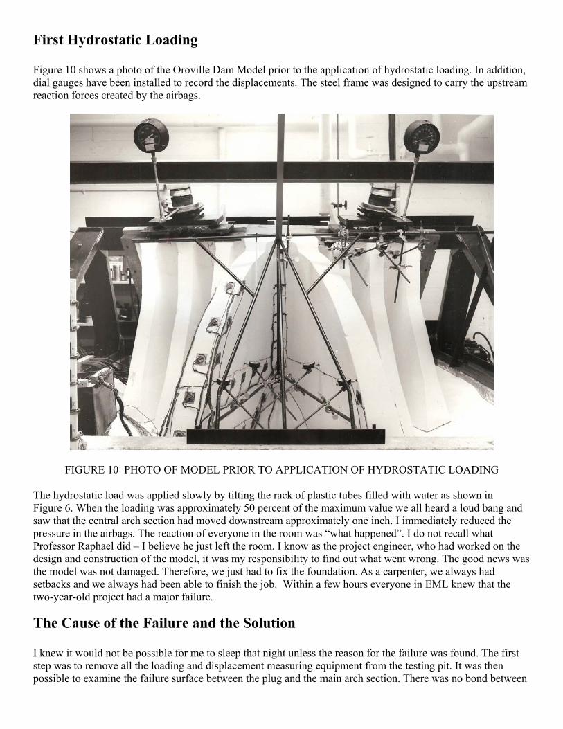
Instrumentation The installation of the strain gauges was in progress when the photo shown in Figure 9 was taken.
FIGURE 9 THE INSTALLATION OF THE STRAIN GAUGES WAS IN PROGRESS
It is significant to note that the main arch section was not epoxies to the foundation and was a cold joint where the wet plaster mix was poured on the dry foundation surface. Note, the free standing buttresses were epoxies to the foundation.
(The failure would be at the cold joint)
First Hydrostatic Loading Figure 10 shows a photo of the Oroville Dam Model prior to the application of hydrostatic loading. In addition, dial gauges have been installed to record the displacements. The steel frame was designed to carry the upstream reaction forces created by the airbags.
FIGURE 10 PHOTO OF MODEL PRIOR TO APPLICATION OF HYDROSTATIC LOADING
The hydrostatic load was applied slowly by tilting the rack of plastic tubes filled with water as shown in Figure 6. When the loading was approximately 50 percent of the maximum value we all heard a loud bang and saw that the central arch section had moved downstream approximately one inch. I immediately reduced the pressure in the airbags. The reaction of everyone in the room was “what happened”. I do not recall what Professor Raphael did – I believe he just left the room. I know as the project engineer, who had worked on the design and construction of the model, it was my responsibility to find out what went wrong. The good news was the model was not damaged. Therefore, we just had to fix the foundation. As a carpenter, we always had setbacks and we always had been able to finish the job. Within a few hours everyone in EML knew that the two-year-old project had a major failure.
The Cause of the Failure and the Solution I knew it would not be possible for me to sleep that night unless the reason for the failure was found. The first step was to remove all the loading and displacement measuring equipment from the testing pit. It was then possible to examine the failure surface between the plug and the main arch section. There was no bond between

the two surfaces since they were poured at different times when one plug was dry and the arch was liquid. In addition, both surfaces were damp. So, where was the water coming from? I started to dig into the foundation near the corner of the test pit and found that below 6 inches from the surface the water in the material continued to increase. Near the bottom of the test pit the material was essentially mud. If the foundation had been dry, the solution would have been very simple. We could just epoxy the arch section back on the foundation and continue to test the model. No big deal. However, it was now apparent the complete foundation had to be removed and replaced. Also, we had to create a new surface section to epoxy the model back to its original position in the test pit. In my mind the problem which had to be solved had been defined and now I could get a good night sleep and work on the solution in the next few days. It was apparent everything in the test pit had to be removed and all the model pieces which were put back into the pit must be 100 percent dry. I then checked all the ovens in EML and determined the maximum sized block that we could dry within 24 hours and could be carried easily. We then carefully removed the arch with all its strain gauges and the switching system and moved them away from the test pit. I then looked at the foundation surface, plug and the four free standing buttresses for a few hours and decided they could be saved or recast. Within three days after the failure my plan was to cast and dry 20 by 30 by 4 inch blocks. We had oven capacity to cast and dry approximately 4 blocks every day. We needed approximately 60 blocks to replace to form a new foundation. Therefore, it would take approximately 15 days to replace the foundation. See Figure 11
FIGURE 11. APPROXIMATE CUTAWAY VIEW OF THE NEW BLOCK FOUNDATION
I presented the plan to Professor Raphael. He was an old Navy man, a high ranking officer on one of the large battleships in WWII and he had assumed “the ship had sunk” when the model failed. He was worried about the budget and the large number of people to do the job. I said, “don’t worry! Gene Croy and I can do it without any help”. He still did not approve my proposal. Of course, I took my plan to Professor Eberhart and he gave approval without hesitation.

Rebuilding the Foundation and Model Gene Croy was about my age and had interrupted his professional career to return to Cal for a MS degree. Gene was smart and knew how to work with his hands. He had not worked on the project long; however, he understood our plan completely. Working side by side we removed and salvaged the buttresses and surface of the foundation including the plug which had been attached to the foundation with epoxy. We only saved the top several inches of the foundation which was excavated in four blocks. I then had one of the permanent staff at EML clean out the pit and Gene and I built the several wooden forms for the foundation blocks. This required approximately two days. The rate we could produce the blocks was governed by the capacities of the ovens. We found that in one day Gene and I could produce 20 wet blocks. Our oven had the ability to dry four blocks in 24 hours. Every morning we would remove the blocks from the oven and test them to make sure they were dry and had the appropriate stiffness. If they meet our acceptance criteria they moved to the test room. When we had enough dried blocks to complete one layer Gene and I would epoxy the dried block in their final location. Another task we worked on during this period was to make sure the four pieces of the foundation were dry. Also, we had to trim the bottom surface of the blocks to insure they would be at the same elevation and location as they were prior to the failure. After the foundation was restored we attached, with epoxy, the 100 percent dried main arch and the four buttresses. Finally, we reinstalled the loading system and all instrumentation. Approximately four weeks after the failure we were ready to apply the hydrostatic load for the second time. During this phase of the project I worked seven days a week and did not keep track of my time. Some days I worked a few hours and other days I worked 10 hours. Gene was always there to help when two people were needed. The hard work was no big deal for me since I had worked 57 days straight at American Can Company and longer hours as a hired man on a dairy ranch. Also, I was a single man and lived on Hearst Avenue only 50 yards from EML.
Hydrostatic testing of the Oroville Model Gene and I decided to start testing the model alone and methodically checking out the response of the system after each load increment. Everything appeared to be working fine. We loaded and unloaded the system several times and started taking readings of displacements and strains. Results were the same for different loading cycles. There was no need for high fives. The personal satisfaction of repairing the failure was all we wanted. The next day we recorded the data for full hydrostatic loading using three separate tests. Then, I when into Professor Raphael’s office and basically told him the hydrostatic phase of the project was complete. He could not believe it until he went to the model room and saw Gene and I load and unload the model. Within a few hours everyone in EML learned the Oroville Dam Project was back on schedule.
Gravity analysis of the Oroville Dam Model As part of my material property research, Professor Raphael asked me to develop a high density plaster-barite material which I made with several different barite/plaster ratios. At that time several major material laboratories were using heavy model material to predict dead load. After the model of the instrumented dam was created all gauges were read and the dam and the foundation were inverted. If the gauges were read in the inverted position the difference in the readings would be approximate twice the dead load strains. Also, these heavy models could be tested on a centrifuge. I did some simple calculation on the geometry of the Oroville Dam and showed the deformation in the foundation would create large strains in the arch. Therefore, I terminated my research on heavy model materials.

However, I continued to think about the problem for the Oroville model. Prior to the hydrostatic testing I had devised a very simple and inexpensive solution. I thought why not reverse the construction sequence and apply a uniform load on the horizontal surface (simulating the weight of one foot of concrete) and then read all the strain gauges below that level. After these tests you could numerical integrate the effects of all loads above that level as illustrated in Figure 12 and 13.
FIGURE 12 METHOD OF INTEGRATION FOR DEAD LOAD STRESSES
FIGURE 13 GENE CROY AND ED WILSON CONDUCTING THE DEAD LOAD TESTING THE LOADING WAS APPROIMATELY ONE TON OF LEAD BRICKS
For the dead load testing we used a different procedure because it took a long time to place the bricks exactly in the correct position. Therefore, we placed the bricks in their position at the end of the day. The test room was a constant temperature, low humidity, control room. The next morning, we would read and record the strain gauges data three times. We then would remove the ton of bricks in less than ten minutes. Then we would read
the gauges three more times. After reviewing the data, I estimated that our measured strains were accurate within 0.5 micro inches. Gene Croy worked the next several months converting all the strains to stresses and preparing the figures for the final report. This was the first application of the method of integration for the calculation of dead load stresses in dams. However, within a few years most of the major laboratories in the world were using the method. In summarizing the material for this paper, I found my initial handwritten proposal, dated Sept. 12, 1958, to use this method on the model. I saved it for nearly 60 years indicating that I believe it was one of my best ideas. However, the life of the method did not last long. Within the next 10 years Professor Clough, I and our students developed computer programs for the analysis of dams including construction stresses, temperature changes, creep of the concrete and the potential for cracking. Also, in a few more years we were simulating the earthquake response of dam-reservoir systems.
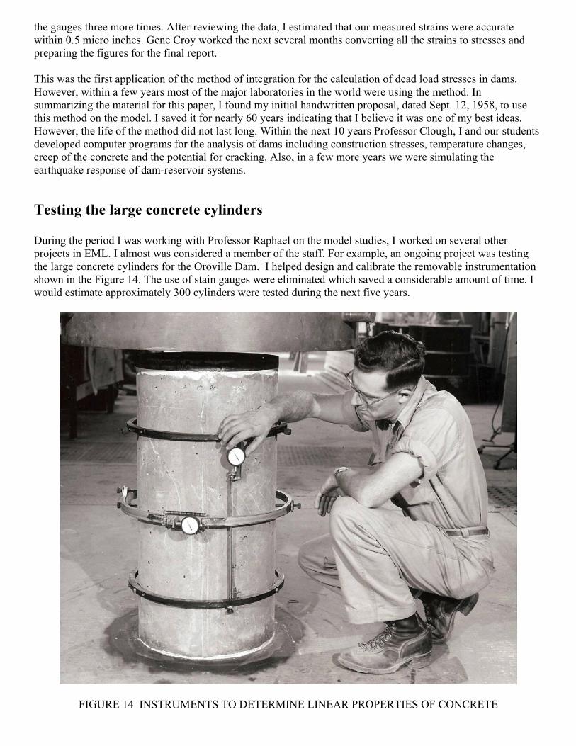
Testing the large concrete cylinders During the period I was working with Professor Raphael on the model studies, I worked on several other projects in EML. I almost was considered a member of the staff. For example, an ongoing project was testing the large concrete cylinders for the Oroville Dam. I helped design and calibrate the removable instrumentation shown in the Figure 14. The use of stain gauges were eliminated which saved a considerable amount of time. I would estimate approximately 300 cylinders were tested during the next five years.
FIGURE 14 INSTRUMENTS TO DETERMINE LINEAR PROPERTIES OF CONCRETE

FIGURE 15 THE CYLINDERS DID NOT FAIL SLOWLY – THEY EXPLODED
Returning to Graduate School In August 1959 I was very happy working on interesting projects and had no plans to change my life. One day I passed Professor Eberhart in one of the hallways of EML. He said drop by my office when you have time. I assumed he wanted to talk to me about another project. That afternoon I went to his office and sat down. He looked me straight in my eyes and said ‘I think you should get a doctor’s degree”. I did not know what to say – I did not what to return to hearing boring lectures and doing homework. Howard continued and said he had been watching me for over six years and told me I had unique ability to solve structural engineering problems. Then he said something to the effect he though I might make a good faculty member at Berkeley. I told him that I did not want or need a doctor’s degree; however, I would think about it. A few days later, Professor Clough came to my office and told me he had receive a grant to continue his work research on computer analysis of structures and ask if I would like to work on his project. What could I do, the two professors I admired the most at Berkeley wanted me to return to Graduate School. At the end of September 1959 I returned to Graduate School. PS After Jerry Raphael died in 1989 I cleaned out his office and found the attached letter: (Maybe, three people were involved in a conspiracy to con me to work for a doctor’s degree!)