modal parameters for a flat plate - missouri s&t
TRANSCRIPT

MODAL PARAMETERS FOR A FLAT PLATE SUPPORTED BY AN OIL FILM
Andrew Jauhola1, Edward Kinzel2, Derek Reding3, Norman Hunter4
1Dept. of Mechanical Engineering, Rose-Hulman Inst. of Technology. Terre Haute, IN, 47803 2Dept. of Mechanical Engineering, Purdue University. West Lafayette, IN, 47907 3Dept. of Mechanical Engineering, Colorado St. University. Fort Collins, CO, 80523 4Weapon Response Group, Los Alamos National Laboratory. Los Alamos, NM, 87545
ABSTRACT This paper examines the resonant frequencies, mode shapes, and damping values for a square plate supported by an oil film. Such a study is motivated by interest in oil-supported slip tables used for vibration testing. Resonant frequencies and percent critical damping were measured for four cases: plate freely suspended; plate with free end conditions and supported by an oil film; plate fixed at several locations; and plate fixed at several locations while supported by an oil film. Analytical estimates of the modal properties and modal properties derived from measured data are compared and discrepancies discussed. 1 INTRODUCTION Slip tables are used frequently for lateral vibration testing. They consist of a flat metal plate, which is vibrated in the horizontal direction. The plate is supported by either an oil film, a set of linear oil bearings, or combination of both. Ideally, the table configuration provides large support in the vertical direction while adding a minimum amount of resistance to travel in the horizontal direction. An additional benefit of hydrodynamic support is the damping of vibration in the vertical direction caused by coupling from excitation in the horizontal direction (cross-talk). This study investigates the modal parameters of a plate for four boundary conditions: freely suspended (FF), simply supported near the four corners (SS), free end conditions and supported on top of an oil film (FFO), and simply supported near the four corners and supported on top of an oil film (SSO). In addition, each case was repeated with a cantilever load to simulate a device under test. The FFO case represents the slip table supported by an oil film and the SSO case to simulate a slip table with the addition of four linear bearings. The cases without oil support were performed for model validation and control. 1.1 Previous Research: Amabili, Frosali, and Kwak [1] show that a fluid will significantly restrain the movement of a plate orthogonal to the face in contact with the slider. The force is related to the velocity of the plate because of surface tension and primarily viscous effects of the fluid. Hansen [2] and Adams and Sorenson [3] first analyzed plates supported by oil films. Hansen [2] discussed a motivation for performing horizontal
vibration testing. Adams and Sorenson [3] examined the mechanisms responsible for the adhesive restraint on a vibrating slider provided by an oil film. They concluded that viscous effects are responsible. Closed form solutions of plate modes were presented by Leissa [4] and are useful in comparison with experimental modes for the oil free data. The plate Leissa used was assumed to be vibrating freely in a vacuum and had negligible transverse displacement. The plate also had a length to thickness ratio (aspect ratio, for this paper) greater than 1:10, and was assumed to be linearly elastic, isotropic, and homogeneous. Ewins [5] described experimental modal analysis procedures that are applicable to this problem. Problems associated with resonant frequencies in test fixtures were shown by Avitabile [6]. The work in this study attempts to model modes of a flat plate on a thin oil film by impact testing. The goal is to better understand out-of-plane cross-talk experienced by a structure on a slip table as well as the effects of boundary constraints on the out-of-plane cross-talk. Section 2 in this paper describes the experimental setup and the plate testing procedures. Section 3 summarizes experimental results as well as analytical results obtained from handbook values and the finite element model. Section 4 compares plate modes for the FF and SS with and without oil support. 2 EXPERIMENTAL PROCEDURE It was impractical to perform a modal analysis on a complete slip table as part of the Los Alamos Dynamics Summer School. This limitation is why a smaller plate and base were used to simulate an actual slip table and base. A Lexan plate was selected because it is transparent and it is easy to check that no air bubbles are under the plate in the cases when it is supported by oil. The plate was labeled with 16 points to be analyzed (see Figure 1). Points 17 and 18 were at the top and bottom of the cantilever, respectively. The cantilever beam in Figure 2 was glued to the center of the plate to simulate a load. Material properties of the Lexan plate and the cantilever beam are included in Table 1. See Figure 2 for the summaries of the dimensions and material composition of the cantilever. The oil used was Quaker State 10W-30.
The 32:1 aspect ratio was selected to simulate a scale model of a vibration slip table. These dimensions also satisfy thin plate assumptions for both the shell elements used in the finite element model as well as the Rayleigh-Ritz method used to establish the closed-form solutions of the plate modal properties [4]. Threaded holes were drilled half way through the plate thickness at 16 points on the plate to provide better test repeatability. A small, threaded metal stud was inserted into these holes then impacted with the hammer.
Table 1: Material properties Material Density Modulus Poisson's
(kg/m3) (GPa) Ratio Lexan 1170. 1.39 0.37 Steel 7872 200. 0.20 Aluminum 2705 69.0 0.33
Four test configurations were used (see Figures 3-5):
1. Free-Free Case: Lexan plate supported by surgical tubing.
2. Oil Supported Free-Free Case: Support using an oil film on a flat steel block larger than the Lexan plate.
3. Simply Supported Case: Support with fixed corners. 4. Oil Supported Fixed Case: Support using an oil film
and fixed corners. The thickness of the oil film was approximately 3.2 mm. In each case the plate modes were obtained for the unloaded plate and the plate loaded with the cantilever. Impact excitation using a modal hammer was conducted. A nylon tip was used for the hammer to excite at least the first four modes. Four accelerometers were used to acquire data (three on the corners and one near the middle of the plate). Hammer impacts were conducted at 16 locations on the plate (see Figure 1) and two locations on the cantilever (see Figure 2). Figures 3-5 illustrate three cases: oil, free, and simply supported boundary conditions. For each case modal frequencies were determined using the ME'scope experimental modal analysis software. Analytical finite element computations using ABAQUS were compared to the experimental results for the free-free cases.
Figure 1: Plate with test points
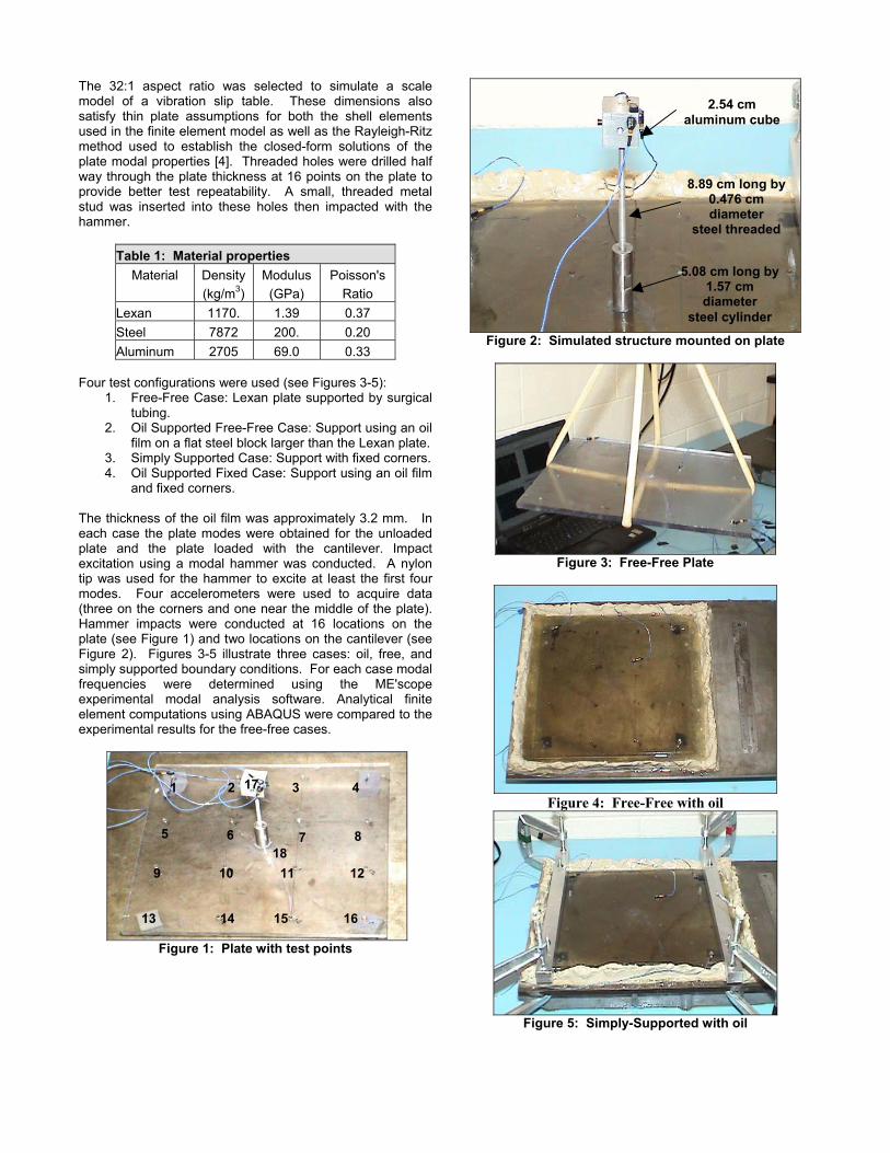
2.54 cm aluminum cube
Figure 2: Simulated structure mounted on plate
Figure 3: Free-Free Plate
Figure 4: Free-Free with oil
Figure 5: Simply-Supported with oil
8.89 cm long by0.476 cm diameter
steel threaded
5.08 cm long by1.57 cm diameter
steel cylinder
1 2 17 3 4
5 6 8 7 18
9 10 11 12
13 14 15 16

3 DATA ANALYSIS 3.1 Experimental Analysis FRF data were obtained with the DACTRON data acquisition system. The experimental modal parameters were obtained using Vibrant Technology’s ME’scopeTM. ME’scopeTM uses curve fit estimation to find the mode shapes and natural frequencies. This curve-fitting procedure assumes that the system is linear and time invariant. 3.2 Finite Element Analysis The analytical portion of this project consisted of a finite element model of the various cases of our flat plate. ABAQUS CAE was used to build this model. ABAQUS does not calculate damping in the model that it uses. Proportional damping may be entered through the material model. All results obtained from ABAQUS models assume linearity with no damping unless it is entered. The data from the FF case was used to validate the ABAQUS model. The first iteration of the model used solid elements to simulate the plate. This model returned results that were significantly different than the experimental data obtained from the FF case. Because the Lexan plate has a width to thickness ratio of much greater than 10:1, a second iteration utilized shell elements. This model returned results comparable to the experimental data when the nominal material properties of Lexan mentioned previously in Table 1 were used. Several iterations of the simply supported case were attempted. For the first three iterations, boundary conditions were applied to small portions of the plate. These boundary conditions constrained those areas in all three transnational degrees of freedom. A fourth model was attempted to more closely model the physical situation. Four small rectangular prisms (meant to simulate the nuts the plate actually rested on) were placed under the plate and fully constrained. The plate was then held on to these rectangular prisms by point loads of 30 N. This final model proved to come the closest to the experimental data from the SS case. The FF and SS cases mentioned were also run with a test load to simulate the cantilever load. Several attempts to model the plate on an oil film were made. One attempt used a film contact condition to model the oil; another attempt modeled the oil as a solid element with a low elastic modulus. At the advice of Richard Macek, Los Alamos National Laboratory, the properties of the solid element were modified as follows. This oil film was made two elements thick. The material properties used included the true oil density, a Poisson’s Ratio of 0.499999 and the true bulk modulus of the oil. The bulk modulus was not entered explicitly in ABAQUS, instead it was used to calculate the elastic modulus in the following equation:
( )ν213 −= KE , where ν = Poisson’s Ratio, K = bulk modulus, and E = elastic modulus. Unfortunately, this model never gave any useful results. The plate never vibrated, only the elements representing the oil made wild vibrations.
4 RESULTS The mode shape names are summarized in Table 2. The first four modes are characterized by frequency and damping percent in Table 3.
Table 2: Mode Shapes FF SS 1 First Torsional First Bending 2 Saddle Long sides out of phase 3 First Bending Short sides out of phase 4 Diagonal Bending Second Bending
Table 3: Experimental Results (Oil Free Cases) FF SS Mode Freq (Hz) Damp % Freq (Hz) Damp %
1 88.3 0.477 86.6 3.62 2 177 0.344 149 1.07 3 232 0.974 *181/184 *0.648/0.414 4 *430/433 *0.449/0.5 357 0.442
FF with Load SS with Load 1 88.8 0.348 - - 2 153 0.345 - - 3 232 0.665 - - 4 379 1.15 - -
* Two resonant frequencies may be observed for the same mode shape. Extraordinarily high damping was observed and mode shapes were hard to determine for some oil-supported cases. Complex mode shapes not described earlier in Table 2 can be observed in the oil free cases (see Table 4). The frequency and damping parameters are shown with two significant digits because of the variance in the experimental data. For all cases, the oil changes the frequency of the system. The finite element results in Table 5 are provided for the non-oil cases only. Cantilever damping for the first bending mode was slightly higher for the oil cases (see Table 6).

Table 4: Experimental Results (Oil Cases)** Mode FF SS Freq (Hz) Damp % Freq (Hz) Damp %
1 80.4 6.54 82.9 9.52 2 196 11.5 197 6.3 3 263 7.52 298 5.08 4 352 11.7 391 4.37
FF with Load SS with Load 1 115 16.8 169 6.51 2 311 0.895 310 1.08 3 371 10.1 414 1.52 4 522 6.1 575 2.88
**Note: most oil modes are complex and do not match the naming scheme used in the table.
***Mode not found in experimental data. Table 6: Cantilever Modes Boundary X1 Damp 1 A1 FF - Load *56.1/56.6 *0.827/0.661 *47.66/48 SS - load *47.9/53.8 *1.78/1.37 *67.7/68 FF - Load - oil *47.9/48.2 *2.65/0.933 - SS - Load - oil *47.4/47.5 *1.76/2.23 - * Two resonant frequencies may be observed for the same mode shape. 5 COMPARISON OF MODES FOR VARIOUS SUPPORT
CONDITIONS Comparisons between the experimental and finite element mode shapes for the first thee modes of the FF case are shown in Figures 6-8. A Modal Assurance Criteria (MAC) value in excess of 0.9 generally indicates correlated modes while a value of less than 0.05 indicates uncorrelated modes [5]. Generally, the correlation decreased at higher frequencies for each case. The following formula is used for correlation:
( )∑∑
∑
⋅
=
=
=
*
1
*
2
1
*
)()()()(
)()(),(
jAjX
n
jjAjX
n
jjAjX
XAMACφφφφ
φφ
Where φX represents an experimental mode shape, φA is an analytical or theoretical mode shape, n is the number of degrees of freedom, and j stands for an index of the degrees of freedom. The complex-conjugate is denoted by *. Figures 6 through 8 show visualizations of modes 1 through 3 in the FF case, respectively. They also indicate the correlation coefficient (MAC number) between the analytical and finite element results.
Finite element Experimental
Figure 6: Mode 1, MAC = 0.9991
Finite element Experimental
Figure 7: Mode 3, MAC = 0.9993
Table 5: ABAQUS Results - Frequency (Hz) Mode FF SS FF - Load SS - Load
1 89.9 82.8 90.18 72.3 2 ***133 149 ***134 156 3 174 172 159 178 4 *235/236 346 *235/235 288
Finite element Experimental
Figure 8: Mode 4, MAC = 0.9129 Clear, distinct modes were obtained for the FF case. There were a few modes that appear in the finite element model that do not appear in the experimental data. For example, the ABAQUS model shows a saddle mode at 133 Hz in the FF case, which does not appear in the experimental data. Also, there were a few modes in the experimental data that did not appear in the ABAQUS model. For example, the fourth mode in the FF case is a bending mode instead of the double bending mode from ABAQUS at that frequency.

Experimental, finite element analysis, and closed form results are shown for the oil free FF case in Table 7. These values show less than 4% error among the three methods. Damping for the non-oil cases was generally low. The FF case provides damping in the range of 0.5% as indicated previously in Table 2. Damping is much greater for the oil-supported cases in Table 3.
Comparisons between the FRF’s of the oil and non-oil cases for several points are shown in Figures 9-11. In Figure 9 the modes of the non-oil supported, free-free case form distinct peaks near 80 Hz, 180 Hz, 425 Hz, and 580 Hz. These modes are very lightly damped as indicated in Tables 3-6. For the oil-supported cases, the damping is very high and only broad peaks are present in the FRF. For this light plate, and relatively thick oil film the behavior of the oil strongly affects the behavior of the plate, by increasing damping and by changing the observed mode shapes. Figures 9-11 each show two FRF’s taken from the same point of impact and point of measurement. For the freely supported case in Figure 9, the damping is much greater with the oil present and the peaks in the oil damped FRF’s are broader. Furthermore, a frequency shift of approximately 30 Hz is shown for the oil case in Figure 9. The phenomenon is similar for the simply supported case shown in Figure 10. However, oil does not change the amplitude of the response For the cantilever-loaded case in Figure 11, the oil strongly damps the table motion. Compared to the no load case, the load does transmit sufficient energy to the table to define some peaks in the FRF, but these are broad and are highly damped.
Figure 9: FF comparison of oil on plate
Table 7: Methods for the FF Case Mode Experiment ABAQUS Leissa
1 88.3 89.9 89.3 2 177 174 171 3 232 235 - 4 431 428 431
Figure 10: SS comparison of oil on plate
Figure 11: Comparison with Cantilever
When comparing the FFO and SSO cases (Figure 12), no significant difference in amplitude or damping can be ascertained.
Figure 12: FFO compared to SSO
The polar plots shown in Figure 13 show the magnitude and phase of the FRF data. Ideally, the phase is 0 or 180 degrees for a proportionally damped system. Complex modes are indicated by phase angle other than 0 or 180 and can result from non-proportional damping.

non-oil oil
Figure 13: Polar plots of oil vs. non-oil 6 CONCLUSION The modal parameters for the four cases were obtained with and without the cantilever beam attached. The oil damped modes considerably in the vertical direction. Correlation between the experimental and the ABAQUS model significantly decreased as the frequency increases for the first 4 modes. In Conclusion: The FF case is readily modeled using ABAQUS, and modal frequencies and mode shapes compare well between experiment and model. These modes are generally lightly (about 1% or less) damped, providing a near linear experimental model. All oil-supported cases significantly restrain table vertical motion. Fixing the corners of the plate provides additional restraint. However, no significant change in damping was observed between the FFO and the SSO cases. Any case with oil introduces considerable damping. Damping ranges from 5-15% for the oil supported cases. The modes were difficult to model with the finite element code. Nonlinear behavior is observed as evidenced by shifts in resonant frequency with excitation amplitude. Mode shapes in the oil and free cases do not compare well, indicating that oil effects are not limited to damping, but fundamentally effect mode shapes and modal frequencies. A comparison of the damping characteristics between the FFO and the SSO conditions show that the fixed corner simulation of linear bearings does reduce the out-of-plane motion of the plate. It can be concluded from this study that oil slip tables with linear bearings do not have more favorable modal characteristics than slip tables supported by an oil film only. Both configurations provide considerable damping, but the linear bearing case is better because the vertical motion is more restricted. The plate tested here is much smaller and less massive than is an actual slip plate. For more massive plates, the plate modes may dominate the behavior more than the scale model Lexan plate. A thin oil film would be expected to provide considerable damping, however, even for a massive plate. If this experiment were run again, a small vibration machine would be used to excite the plate. FRF’s would then be
computed using steady state excitation. Hopefully, this would yield improved oil case mode shapes. Other methods of minimizing vertical motion could also be tested. Stiffening the ends of the plate is among the possibilities. Also, different loads could have been tried. Completing the finite element model would be of high priority in a continuation of this project. If this project were to extend to redesigning a slip table, the finite element model could be used to assist in the redesign of a slip table. Designing a table that avoids resonant frequencies of typical test items is a possibility. More time would have allowed an analytical solution using Rayleigh-Ritz and Navier-Stokes equations. Other work that could be performed could include a consideration of scaling effects in proceeding from a scale model test to the full size test item. Modal testing of a full size slip plate could also be conducted and the modes compared to those of the scale model plate. 7 ACKNOWLEGEMENTS Funding for the Los Alamos Dynamics Summer School was provided by the Engineering Science and Applications Division at the Los Alamos National Laboratory and the Dept. of Energy’s Education Programs Office. The following companies provided data acquisition hardware and various software packages that were necessary to complete the project: Dactron, Inc. (data acquisition hardware), Vibrant Technologies (experimental modal analysis software), and Hibbitt, Karlsson & Sorensen, Inc. (finite element software). Richard Macek’s input helped us with the finite element model. 8 REFERENCES [1] M. Amabali, G. Frosali, M. K. Kwak. “Free Vibrations of Annular Plates Coupled with Fluids”. Journal of Sound and Vibration (1966) 191, 825-846. [2] W. O. Hansen. “A Novel High- and Low-Temperature Horizontal-Vibration Test Fixture”. General Electric Co. 25th Shock and Vibration Symposium (1957) 93-102. [3] Edward C. Adams and Arthur Sorenson, Jr. An Experimental and Theoretical Study of an Oil Film Slider. “AC Spark Plug Division, General Motors Corporation”. Milwaukee, Wisconsin. [4] A. W. Leissa. Plates. 2001 Academic Press doi:10.1006/rwvb.2001.0129 (1024-1027). [5] D.J. Ewins. Modal Testing: Theory and Practice. Research Studies Press LTD (1984) 1-55. [6] Peter Avitabile. Why You Can’t Ignore Those Vibration Fixture Resonances. Personal Communication