modbus - serwer pomocy technicznej elmark...
TRANSCRIPT

i
MODBUS MODBUS Help Rev: 2/12/04
Table Of Contents MODBUS......................................................................................................................................... 1
MODBUS Help Rev: 2/12/04 .....................................................................................................i Using MODBUS: Unitronics' PLCs, Master - Slave ................................................................. 1 Using MODBUS: Accessing PLC data via SCADA/OPC server.............................................. 2 FB Operations .......................................................................................................................... 3 Examples.................................................................................................................................. 4
MODBUS: Configuration.............................................................................................................. 5 MODBUS: ScanEX and Scan...................................................................................................... 6 Read Coils (1) .............................................................................................................................. 7 Read Inputs (2) ............................................................................................................................ 8 Read Holding Registers (3).......................................................................................................... 8 Read Float Registers (3).............................................................................................................. 9 Read Input Registers (4)............................................................................................................ 10 Read Float Registers (4)............................................................................................................ 11 Force Coil (5) ............................................................................................................................. 12 Preset Holding Register (6)........................................................................................................ 13 Loopback Test (8) ...................................................................................................................... 14 Force Coils (15) ......................................................................................................................... 14 Preset Holding Registers (16).................................................................................................... 15 Preset Float Registers (16) ........................................................................................................ 16 Read/Write from Data Tables .................................................................................................... 17
Read from Data Table ............................................................................................................ 17 Write to Data Table ................................................................................................................ 18
Configuring a MODBUS slave device........................................................................................ 19 Slave Addressing ....................................................................................................................... 20
Slave Address Tables ............................................................................................................ 20 MODBUS via GSM or Standard Modem ................................................................................... 23 MODBUS Status Operands ....................................................................................................... 24
Index .............................................................................................................................................. 29


1
MODBUS MODBUS enables you to establish master-slave communications with any connected device that supports the MODBUS protocol. Any controller in the network may function as either master or slave using any of the controller's existing COM Ports.
Within a MODBUS network, you can use standard MODBUS commands to read and write bit and register data; you can also read and write data to Vision controller Data Tables.
Unitronics currently supports RTU (binary) transmission mode.
Using MODBUS: Unitronics' PLCs, Master - Slave Before using a MODBUS operation in your application, you must:
Synchronize the communication port settings of master and slave devices. This is done by placing COM Port Init FBs, set with identical parameters, in the ladder application of both master and slave.
Include at least 1 MODBUS Configuration FB in the ladder application of both master and slave. The port you select must be the same port selected in the COM Port Init FB.
The condition that activates the Configuration must turn ON for a single program scan (positive transition recommended).However, the MODBUS configuration must be scanned during every program cycle--after the Configuration is activated. One way to ensure this is by placing the configuration in the first subroutine of the main module.
Enable slave devices to be accessed by placing a Scan_EX FB in the slave's Ladder application.
The figure below shows the elements required to carry out a Read Coils Operation.

MODBUS
2
Note that the operand addresses in slave PLCs are indirect addresses (pointers).
Using MODBUS: Accessing PLC data via SCADA/OPC server
The PC master can access data within the PLC via the addresses given in the Slave Addresses Table.
The PLC slave's Ladder application must include the following:
A COM Port Init FB.
A MODBUS Configuration FB. Within the Configuration, the port you select must be the same port selected in the COM Port Init FB. Note ♦ The condition that activates the Configuration must turn ON for a single program scan (positive transition recommended).However, the MODBUS configuration must be scanned during every program cycle--after the Configuration is activated. One way to ensure this is by placing the configuration in the first subroutine of the main module.
A Scan_EX FB.

MODBUS
3
Note ♦ The operand addresses in slave PLCs are indirect addresses (pointers).
FB Operations
Operations are grouped under MODBUS on the FB's menu.

MODBUS
4
M O D B U S : C o n f i g u r a t i o n
M O D B U S : S c a n
M O D B U S : R e a d C o i l s ( 1 )
M O D B U S : R e a d I n p u t s ( 2 )
R e a d H o l d i n g R e g i s t e r s ( 3 )
R e a d F l o a t R e g i s t e r s ( 3 )
R e a d I n p u t R e g i s t e r s ( 4 )
R e a d F l o a t I n p u t R e g i s t e r s ( 4 )
F o r c e C o i l ( 5 )
P r e s e t H o l d i n g R e g i s t e r ( 6 )
L o o p b a c k T e s t ( 8 )
F o r c e C o i l s ( 1 5 )
P r e s e t H o l d i n g R e g i s t e r s ( 1 6 )
P r e s e t F l o a t R e g i s t e r s ( 1 6 )
R e a d / W r i t e t o D a t a T a b l e s
Examples Sample applications may be found in the VisiLogic Examples folder. This folder contains field-tested VisiLogic (.vlp) sample applications. You can open this folder via the Help Menu.

MODBUS
5
The folder is typically located at: C:\ProgramFiles\Unitronics\VisiLogic\Examples\Verx.xx, where x.xx indicates the version of VisiLogic.
MODBUS: Configuration A MODBUS Configuration FB must be included in both master and slave Ladder applications as shown below.
Parameter Type Function
Port Number Constant Click the drop-down arrows to view available ports; click the port you want to use.
Network ID Constant This number identifies the device on the network. You can either assign an ID via an MI, or directly via a constant number. The unit ID range is from 0-255. Do not assign the same ID number to more than one device.
Time out Constant or MI
This is the amount of time a master device will wait for an answer from a slave. Time out units are defined in 10 msecs; a Time out value of 100 is equal to 1 second.
Retries Constant or MI
This is the number of times a device will try to send a message.
Function in Progress
MB This bit is ON when MODBUS is active. Use this as a condition bit for MODBUS operations to avoid communication conflicts.
Note ♦ Indirectly addressed parameters in a MODBUS Configuration FB are only read when the Configuration is called. Since a Configuration is generally called as a power-up task, if, for example Retries has been indirectly addressed, and the linked MI is updated, the new value will not be read into the Configuration. The value will only be updated until the Configuration is called.
♦ While a master attempts to send a command, the Function In Progress bit is ON. The number of attempts that the master will make is the number in Retries +1, where '1' is the initial access attempt.
♦ When a master attempts to access a slave device, and the slave does not answer,- the Function In Progress bit will turn ON. This bit will remain on

MODBUS
6
according to the following: (the number of retries + 1) x (Time Out), where '1' is the initial access attempt. Note that the Time Out parameter is in units of 10 msec.
The Ladder application below enables the controller act as a MODBUS master and read coils in a slave PLC. The Scan_EX operation in the final net enables the controller to also act as a slave.
MODBUS: ScanEX and Scan Scan_EX enables a master device to access a slave PLC.

MODBUS
7
Note ♦ Scan_Ex is recommended for new applications.
About Scan and Scan_EX
MODBUS Versions previous to V2.01 offered only the Scan FB. Scan is still supported for older, working applications. When MODBUS operations accessed double registers (5100 addresses and higher), using odd addresses, such as 5101, there were incompatibility issues.
Scan_EX is recommended for new applications.
When ScanEX receives an input parameter in the 32-bit range (for example, 5100{ML}), it automatically takes double-register values. If, for example, ScanEX receives a Read Register(6) request for 5100, it returns the values in 5100 and 5101. If, however, ScanEX receives Read Register(6) request for 5101, it returns Status Message #2-- since 5101 provides the 'high' bytes of the 32-bit register, it is not a legal address.
Read Coils (1) Use this command to read the status of a selected group of coils and write them into a vector. The coil's status is written into a vector of MBs in the master PLC.
Parameter Type Function
Slave ID Constant or MI
The ID of the slave device containing the coils to be read (data source).
Slave: Start of Vector
Constant, MI, ML, or DW
The start of the vector of coils to be read (data source). Note ♦ Check topic Slave Address Tables
Read: Vector Length
Constant or MI
The vector length. Note ♦ A MODBUS command cannot read/write more than 1900 bit operands at one time. In addition, 0 is not a legal length.
Master: Start of Vector
MB This is the start of a vector of MBs that will contain the coils' status in the master (data destination).
Status Messages MI Shows a message number. To check status and diagnose errors, check the MODBUS Status Messages.
Total Sessions DW This is the number of times the master PLC will attempt to access the slave device. Note that this is a simple incremental counter. Initialize it by storing 0 into the selected DW.

MODBUS
8
Acknowledgements DW This is the number of times the slave device answers.
Read Inputs (2)
Use this command to read the status of a selected group of inputs in a slave device and write them into a vector. The inputs's status is written into a vector of MBs in the master PLC.
Parameter Type Function
Slave ID Constant or MI
The ID of the slave device containing the inputs to be read (data source).
Slave: Start of Vector
Constant, MI, ML, or DW
The start of the vector of inputs to be read (data source). Note ♦ Check topic Slave Address Tables
Read: Vector Length
Constant or MI
The vector length. Note ♦ A MODBUS command cannot read/write more than 1900 bit operands at one time. In addition, 0 is not a legal length.
Master: Start of Vector
MB This is the start of a vector of MBs that will contain the inputs' status in the master (data destination).
Status Messages MI Shows a message number. To check status and diagnose errors, check the MODBUS Status Messages.
Total Sessions DW This is the number of times the master PLC will attempt to access the slave device. Note that this is a simple incremental counter. Initialize it by storing 0 into the selected DW.
Acknowledgements DW This is the number of times the slave device answers.
Read Holding Registers (3) Use this command to read the values of a selected group of registers in a slave PLC and write them into a defined vector of registers in the master.

MODBUS
9
Parameter Type Function
Slave ID Constant or MI
The ID of the device containing the registers to be read (data source).
Slave: Start of Vector
Constant, MI, ML, or DW
The start of the vector of registers to be read (data source). Note ♦ Check topic Slave Address Tables
Read: Vector Length
Constant, MI, ML, or DW
The vector length Note ♦ A MODBUS command cannot read more than 124 16-bit integers, 62 double registers, or 64 float registers at one time. In addition, 0 is not a legal length. ♦ If, within the Slave: Start of Vector parameter, the selected register type is a 32-bit double register (slave addresses 5100 and greater)the preset vector length must be doubled as well. If, for example: - Slave: Start of Vector parameter is set to 6300, and - You wish to preset 4 registers, for a total of 16 bytes - You must set the Preset Vector length to 8. Note that this means that, in these cases, the Preset: Vector Length parameter will always be an even number.
Master: Start of Vector
MI This is the start of a vector of MIs that will contain the registers' values in the master (data destination).
Status Messages MI Shows a message number. To check status and diagnose errors, check the MODBUS Status Messages.
Total Sessions DW This is the number of times the master PLC will attempt to access the slave device. Note that this is a simple incremental counter. Initialize it by storing 0 into the selected DW.
Acknowledgements DW This is the number of times the slave device answers.
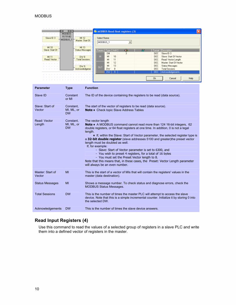
Read Float Registers (3) Use this command to read the values of a selected group of floating point registers in a slave device and write them into a defined vector of registers in the master. Values after the decimal point are rounded to the nearest whole value.
MODBUS
10
Parameter Type Function
Slave ID Constant or MI
The ID of the device containing the registers to be read (data source).
Slave: Start of Vector
Constant, MI, ML, or DW
The start of the vector of registers to be read (data source). Note ♦ Check topic Slave Address Tables
Read: Vector Length
Constant, MI, ML, or DW
The vector length Note ♦ A MODBUS command cannot read more than 124 16-bit integers, 62 double registers, or 64 float registers at one time. In addition, 0 is not a legal length. ♦ If, within the Slave: Start of Vector parameter, the selected register type is a 32-bit double register (slave addresses 5100 and greater)the preset vector length must be doubled as well. If, for example: - Slave: Start of Vector parameter is set to 6300, and - You wish to preset 4 registers, for a total of 16 bytes - You must set the Preset Vector length to 8. Note that this means that, in these cases, the Preset: Vector Length parameter will always be an even number.
Master: Start of Vector
MI This is the start of a vector of MIs that will contain the registers' values in the master (data destination).
Status Messages MI Shows a message number. To check status and diagnose errors, check the MODBUS Status Messages.
Total Sessions DW This is the number of times the master PLC will attempt to access the slave device. Note that this is a simple incremental counter. Initialize it by storing 0 into the selected DW.
Acknowledgements DW This is the number of times the slave device answers.
Read Input Registers (4) Use this command to read the values of a selected group of registers in a slave PLC and write them into a defined vector of registers in the master.

MODBUS
11
Parameter Type Function
Slave ID Constant or MI
The ID of the device containing the registers to be read (data source).
Slave: Start of Vector
Constant, MI, ML, or DW
The start of the vector of registers to be read (data source). Note ♦ Check topic Slave Address Tables
Read: Vector Length
Constant, MI, ML, or DW
The vector length Note ♦ A MODBUS command cannot read more than 124 16-bit integers, 62 double registers, or 64 float registers at one time. In addition, 0 is not a legal length. ♦ If, within the Slave: Start of Vector parameter, the selected register type is a 32-bit double register (slave addresses 5100 and greater)the preset vector length must be doubled as well. If, for example: - Slave: Start of Vector parameter is set to 6300, and - You wish to preset 4 registers, for a total of 16 bytes - You must set the Preset Vector length to 8. Note that this means that, in these cases, the Preset: Vector Length parameter will always be an even number.
Master: Start of Vector
MI This is the start of a vector of MIs that will contain the registers' values in the master (data destination).
Status Messages MI Shows a message number. To check status and diagnose errors, check the MODBUS Status Messages.
Total Sessions DW This is the number of times the master PLC will attempt to access the slave device. Note that this is a simple incremental counter. Initialize it by storing 0 into the selected DW.
Acknowledgements DW This is the number of times the slave device answers.
Read Float Registers (4) Use this command to read the values of a selected group of floating point registers in a slave device and write them into a defined vector of registers in the master. Values after the decimal point are rounded to the nearest whole value.

MODBUS
12
Parameter Type Function
Slave ID Constant or MI
The ID of the device containing the registers to be read (data source).
Slave: Start of Vector
Constant, MI, ML, or DW
The start of the vector of registers to be read (data source). Note ♦ Check topic Slave Address Tables
Read: Vector Length
Constant, MI, ML, or DW
The vector length Note ♦ A MODBUS command cannot read more than 124 16-bit integers, 62 double registers, or 64 float registers at one time. In addition, 0 is not a legal length. ♦ If, within the Slave: Start of Vector parameter, the selected register type is a 32-bit double register (slave addresses 5100 and greater)the preset vector length must be doubled as well. If, for example: - Slave: Start of Vector parameter is set to 6300, and - You wish to preset 4 registers, for a total of 16 bytes - You must set the Preset Vector length to 8. Note that this means that, in these cases, the Preset: Vector Length parameter will always be an even number.
Master: Start of Vector
MI This is the start of a vector of MIs that will contain the registers' values in the master (data destination).
Status Messages MI Shows a message number. To check status and diagnose errors, check the MODBUS Status Messages.
Total Sessions DW This is the number of times the master PLC will attempt to access the slave device. Note that this is a simple incremental counter. Initialize it by storing 0 into the selected DW.
Acknowledgements DW This is the number of times the slave device answers.
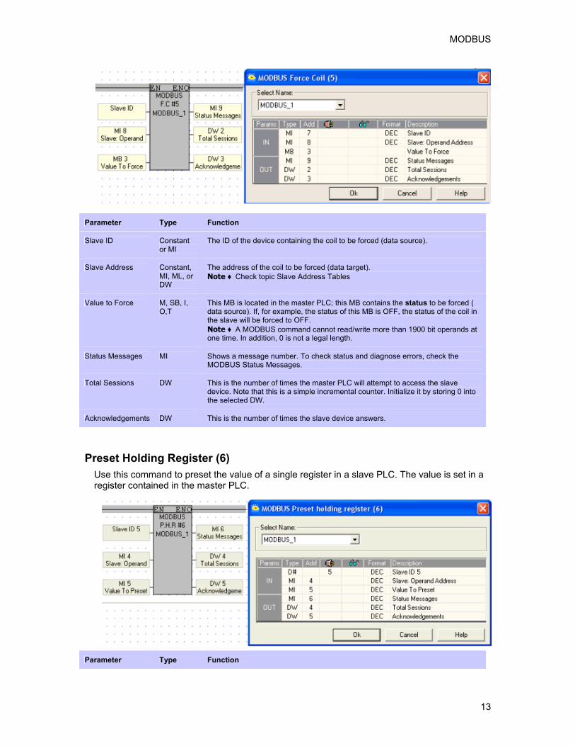
Force Coil (5) Use this command to force the status of a selected coil in a slave PLC. The coil's status is forced according to the status of a selected MB in the master PLC.
MODBUS
13
Parameter Type Function
Slave ID Constant or MI
The ID of the device containing the coil to be forced (data source).
Slave Address Constant, MI, ML, or DW
The address of the coil to be forced (data target). Note ♦ Check topic Slave Address Tables
Value to Force M, SB, I, O,T
This MB is located in the master PLC; this MB contains the status to be forced ( data source). If, for example, the status of this MB is OFF, the status of the coil in the slave will be forced to OFF. Note ♦ A MODBUS command cannot read/write more than 1900 bit operands at one time. In addition, 0 is not a legal length.
Status Messages MI Shows a message number. To check status and diagnose errors, check the MODBUS Status Messages.
Total Sessions DW This is the number of times the master PLC will attempt to access the slave device. Note that this is a simple incremental counter. Initialize it by storing 0 into the selected DW.
Acknowledgements DW This is the number of times the slave device answers.
Preset Holding Register (6) Use this command to preset the value of a single register in a slave PLC. The value is set in a register contained in the master PLC.
Parameter Type Function

MODBUS
14
Slave ID Constant or MI
The ID of the device containing the register to be preset (target).
Slave: Operand Address
Constant, MI, ML, or DW
The address of the register to be preset (target). Note ♦ Check topic Slave Address Tables
Value to Preset Constant, MI, SI, ML, SL, DW, SDW or T
This is the address of the register containing the value in the master PLC (source). This value will be written into the slave's register, the register that is to be preset.
Status Messages MI Shows a message number. To check status and diagnose errors, check the MODBUS Status Messages.
Total Sessions DW This is the number of times the master PLC will attempt to access the slave device. Note that this is a simple incremental counter. Initialize it by storing 0 into the selected DW.
Acknowledgements DW This is the number of times the slave device answers.
Loopback Test (8) Use this command to send a test message to a slave device and receive Acknowledgements when communications are functioning properly.
Parameter Type Function
Slave ID Constant or MI
The ID of the device to be checked.
Status Messages MI Shows a message number. To check status and diagnose errors, check the MODBUS Status Messages.
Total Sessions DW This is the number of times the master PLC will attempt to access the slave device. Note that this is a simple incremental counter. Initialize it by storing 0 into the selected DW.
Acknowledgements DW This is the number of times the slave device answers.
Force Coils (15) Use this command to force the status of a selected group of coils in a slave PLC. The coils' status is forced according to the status of a group of MBs in the master PLC.

MODBUS
15
Parameter Type Function
Slave ID Constant or MI
The ID of the slave device containing the coils to be forced (target).
Slave:Start of Vector
Constant, MI, ML, or DW
The start of the vector of coils to be forced (data target). Note ♦ Check topic Slave Address Tables
Master: Start of Vector
MI, SB, I, O,T
This is the start of a vector of MBs that will contain the coils' status in the master (data source).
Force: Vector Length
Constant or MI
The vector length. Note ♦ A MODBUS command cannot read/write more than 1900 bit operands at one time. In addition, 0 is not a legal length.
Status Messages MI Shows a message number. To check status and diagnose errors, check the MODBUS Status Messages.
Total Sessions DW This is the number of times the master PLC will attempt to access the slave device. Note that this is a simple incremental counter. Initialize it by storing 0 into the selected DW.
Acknowledgements DW This is the number of times the slave device answers.
Preset Holding Registers (16) Use this command to preset the value of a group of registers in a slave PLC. The values are set in a vector of registers contained in the master PLC.
Parameter Type Function
Slave ID Constant The ID of the device containing the registers to be preset (target).

MODBUS
16
or MI
Slave: Start of Vector
Constant, MI, ML, or DW
The start of the vector of registers to be preset (target). Note ♦ Check topic Slave Address Tables
Master: Start of Vector
Constant, MI, SI, ML, SL, DW, SDW or T
This is the start of a vector of MIs that will contain the registers' values in the master (data source).
Preset: Vector Length
Constant, MI, ML, or DW
The length of the vector of registers in both master and slave. Note ♦ A MODBUS command cannot read more than 124 16-bit integers, 62 double registers, or 64 float registers at one time. In addition, 0 is not a legal length. ♦ If, within the Slave: Start of Vector parameter, the selected register type is a 32-bit double register (slave addresses 5100 and greater)the preset vector length must be doubled as well. If, for example: - Slave: Start of Vector parameter is set to 6300, and - You wish to preset 4 registers, for a total of 16 bytes - You must set the Preset Vector length to 8. Note that this means that, in these cases, the Preset: Vector Length parameter will always be an even number.
Status Messages MI Shows a message number. To check status and diagnose errors, check the MODBUS Status Messages.
Total Sessions DW This is the number of times the master PLC will attempt to access the slave device. Note that this is a simple incremental counter. Initialize it by storing 0 into the selected DW.
Acknowledgements DW This is the number of times the slave device answers.
Preset Float Registers (16) Use this command to preset the value of a group of floating point registers in a slave PLC. The values are set in a vector of registers contained in the master PLC. Values after the decimal point are rounded to the nearest whole value.
Parameter Type Function
Slave ID Constant or MI
The ID of the device containing the register to be preset (target).
Slave: Start of Vector
Constant, MI, ML, or DW
The address of the register to be preset (target). Note ♦ Check topic Slave Address Tables

MODBUS
17
Master: Start of Vector
MI, SI, ML, SL, DW, SDW or T
This is the address of the register containing the value in the master PLC (source). This value will be written into the slave's register, the register that is to be preset.
Preset: Vector Length
Constant, MI, ML, or DW
The length of the vector of registers in both master and slave. Note ♦ A MODBUS command cannot read more than 124 16-bit integers, 62 double registers, or 64 float registers at one time. In addition, 0 is not a legal length. ♦ If, within the Slave: Start of Vector parameter, the selected register type is a 32-bit double register (slave addresses 5100 and greater)the preset vector length must be doubled as well. If, for example: - Slave: Start of Vector parameter is set to 6300, and - You wish to preset 4 registers, for a total of 16 bytes - You must set the Preset Vector length to 8. Note that this means that, in these cases, the Preset: Vector Length parameter will always be an even number.
Status Messages MI Shows a message number. To check status and diagnose errors, check the MODBUS Status Messages.
Total Sessions DW This is the number of times the master PLC will attempt to access the slave device. Note that this is a simple incremental counter. Initialize it by storing 0 into the selected DW.
Acknowledgements DW This is the number of times the slave device answers.
Read/Write from Data Tables Use these commands to access the bytes in Vision data tables without reference to table structure.
To determine the byte number of a data table cell, hold the cursor over the data table cell. A Tooltip opens, displaying the byte number.
Note ♦
A MODBUS command cannot read/write more than 242 DT bytes at one time. In addition, 0 is not a legal length.
Read from Data Table Below, a MODBUS master reads data tables in Slave ID 1. Bytes 24-43 are read from Slave 1 into bytes 140-159 in the master's data tables.

MODBUS
18
Parameter Type Function
Slave ID Constant or MI
The ID of the slave device containing the coils to be read (data source).
Slave: DT Start of Vector
Constant, MI, ML, or DW
The start of the vector of bytes to be read (data source).
Slave: DT Offset in Vector
Constant, MI, ML, or DW
Offset from the Slave: DT Start of Vector
Master: DT Start of Vector
Constant, MI, ML, or DW
This is the start of a vector of bytes that will contain the data read from the slave.
Master: DT Offset in Vector
Constant, MI, ML, or DW
Offset from the Master: DT Start of Vector
Read: DT Vector Length
Constant or MI
The vector length. Note ♦ A MODBUS command cannot read/write more than 242 DT bytes at one time. In addition, 0 is not a legal length.
Status Messages MI Shows a message number. To check status and diagnose errors, check the MODBUS Status Messages.
Total Sessions DW This is the number of times the master PLC will attempt to access the slave device. Note that this is a simple incremental counter. Initialize it by storing 0 into the selected DW.
Acknowledgements DW This is the number of times the slave device answers.
Write to Data Table Below, a MODBUS master writes to data tables in Slave ID 1. Bytes 140-159 are written from the master into bytes 24-43 in the slave's data tables.

MODBUS
19
Parameter Type Function
Slave ID Constant or MI
The ID of the slave device to which the data will be written (data target).
Slave: DT Start of Vector
Constant, MI, ML, or DW
The start of the vector of bytes to be written into (data target).
Slave: DT Offset in Vector
Constant, MI, ML, or DW
Offset from the Slave: DT Start of Vector
Master: DT Start of Vector
Constant, MI, ML, or DW
This is the start of a vector of bytes, in the master, that will contain the data to be written to the slave (data source)
Master: DT Offset in Vector
Constant, MI, ML, or DW
Offset from the Master: DT Start of Vector
Read: DT Vector Length
Constant or MI
The vector length. Note ♦ A MODBUS command cannot read/write more than 242 DT bytes at one time. In addition, 0 is not a legal length.
Status Messages MI Shows a message number. To check status and diagnose errors, check the MODBUS Status Messages.
Total Sessions DW This is the number of times the master PLC will attempt to access the slave device. Note that this is a simple incremental counter. Initialize it by storing 0 into the selected DW.
Acknowledgements DW This is the number of times the slave device answers.
Configuring a MODBUS slave device

MODBUS
20
The Ladder section below shows what elements are necessary to enable a master device to read from a slave. Note that the MODBUS Scan_EX operation should not be performed during the initial program scan.
Note that you must use a condition (RLO) to activate the MODBUS Configuration and SCAN _EX.
Slave Addressing Slave Address Tables Coils
MODBUS Command Number
Pointer Value From:
Operand type Read Write
0000 MB 0-2999 #15 Force Coils
3000 SB #15 Force Coils
4000 I (read-only) Read-only
5000 O #15 Force Coils
6000 T(read-only)
#01 Read Coils
Read-only

MODBUS
21
7000 C(read-only) Read-only
8000 MB 3000-4095
Note ♦ Note that in order to access MBs 3000-4095, you address as follows: to access
MB 3012, request slave address 8012. Registers MODBUS Command Number
Pointer Value From:
Operand type Register size Read Write
0000 MI 16 bit
4000 SI 16 bit
5100 ML 32 bit
6100 SL 32 bit
6300 MDW 32 bit
6700 SDW 32 bit
6900 Timer preset 32 bit
7200 Timer current 32 bit
7500 Counter 16 bit
7700 MF 0 32 bit
# 03 Read Holding Registers
# 16 Preset Holding Registers
Examples
The examples below show that: MODBUS addressing systems start at 1. Vision addressing start at 0.
Bit Operands

MODBUS
22
Read a 10-bit vector of inputs in a slave Vision controller, starting at Input 20, via Read Coils ( MODBUS COMMAND #1)
Vision PLC as the MODBUS master In VisiLogic's Read Coils FB, set the Slave: Start of Vector parameter to 4020, and the Read: Vector Length parameter to 10. Within the slave Vision controller, VisiLogic will read I 20 - I 29.
SCADA as the MODBUS master In the SCADA application, set the Slave: Start of Vector parameter to 34021(30001 + 4000 + 20), and the Read: Vector Length to 10, enabling the Master device to read I 20 - I 29 within the slave Vision controller.
Write a 3-bit vector of outputs in a slave Vision controller, starting at Output 8, via Force Coils (MODBUS COMMAND #15)
Vision PLC as the MODBUS master In VisiLogic's Force Coils FB, set the Slave: Start of Vector parameter to 5008, and the Read: Vector Length parameter to 3. Within the slave Vision controller, VisiLogic will write to O 8 - O 10.
SCADA as the MODBUS master In the SCADA application, set the Slave: Start of Vector parameter to 35009 (30001 + 5000 + 8) and the Read: Vector Length parameter to 3, enabling the Master device to write to O 8 - O 10 within the slave Vision controller.
Registers
Read a 9-register long vector of 16-bit integers in a slave Vision controller, starting at MI 32, via Read Holding Registers (MODBUS COMMAND #03)
Vision PLC as the MODBUS master In VisiLogic's Read Holding Registers FB, set the Slave: Start of Vector parameter to 32, and the Read: Vector Length parameter to 9. Within the slave Vision controller, VisiLogic will read MI 32 - MI 41.
SCADA as the MODBUS master In the SCADA application, set the Slave: Start of Vector parameter to 40033 (40001 + 0000 + 3), and the Read: Vector Length parameter to 9, enabling the Master device to read MI 32 - MI 41 within the slave Vision controller.
Note ♦
If, within the Slave: Start of Vector parameter, the selected register type is a 32-bit double register (slave addresses 5100 and greater)the preset vector length must be doubled as well. If, for example in the VisiLogic Preset Holding Registers FB:
Slave: Start of Vector parameter is set to 6300, and You wish to preset 4 registers, for a total of 16 bytes You must set the Preset Vector length to 8.
Note that this means that, in these cases, the Preset: Vector Length parameter will always be an even number.
Read a 9-register long vector of 32 -bit integers in a slave Vision controller, starting at SL 32, via Preset Holding Registers (MODBUS COMMAND #16)
Vision PLC as the MODBUS master In VisiLogic's Preset Holding Registers FB, set the Slave: Preset Vector parameter to 6132, and the Read: Vector Length parameter to 18 ( 2x9, in order

MODBUS
23
to fit the 32-bit SL registers ). Within the slave Vision controller, VisiLogic will read SL 32 - SL 41.
SCADA as the MODBUS master In the SCADA application, set the Slave: Start of Vector parameter to 406133, and the Read: Vector Length parameter to 18, enabling the Master device to read SL 32 - SL 41 within the slave Vision controller.
Write a 6-register long vector of 16-bit integers in a slave Vision controller, starting at MI 32, via Preset Holding Registers (MODBUS COMMAND #16)
Vision PLC as the MODBUS master In VisiLogic's Preset Holding Registers FB, set the Slave: Start of Vector parameter to 32, and the Preset: Vector Length parameter to 6. Within the slave Vision controller, VisiLogic will write to MI 32 - MI 37.
SCADA as the MODBUS master In the SCADA application, set the Slave: Start of Vector parameter to 40033, and the Read: Vector Length parameter to 6,enabling the Master device to write to MI 32 - MI 37 within the slave Vision controller.
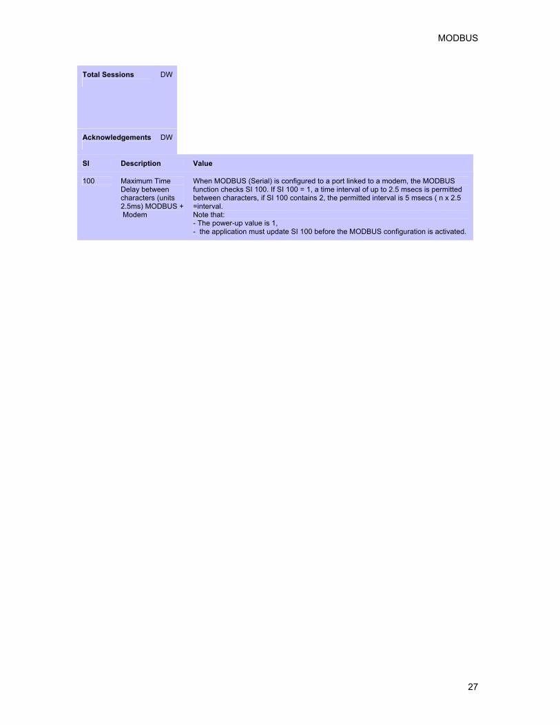
MODBUS via GSM or Standard Modem
Note ♦
When MODBUS (Serial) is configured to a port linked to a modem, the MODBUS function checks SI 100 Maximum Time Delay between characters (units 2.5ms) MODBUS + Modem. If SI 100 = 1, a time interval

MODBUS
24
of up to 2.5 msecs is permitted between characters, if SI 100 contains 2, the permitted interval is 5 msecs ( n x 2.5 = interval. Note that the application must update SI 100 before the MODBUS configuration is activated.
MODBUS Status Operands All of the Status operands linked to MODBUS FBs should be assigned Power-up Values; bits should be reset, and registers initialized to 0.
MODBUS: Configuration FB Status Operand All MODBUS operations run through a MODBUS configuration placed in the master device's program.
Function in Progress Shows status of master's MODBUS Configuration
MB Turns ON when: • A master Vision
initiates MODBUS communication.
• Remains ON during the MODBUS session.
Turns OFF when • The MODBUS: Configuration
is activated. • An answer is received from a
slave. • The TimeOut defined in the
Configuration is exceeded. • Certain Status Messages are
given
MODBUS Operation Status Operands When you place MODBUS operations in your application (Force, Read, Preset, and Loopback commands), you link the operands below. These show the status of MODBUS sessions.
Status Messages Shows status of master's data requests and the replies the master receives from the slaves
MI • Automatically initialized to 0 when MODBUS operation is activated.
• Updated at the end of each attempt to communicate via MODBUS.
• Indicates status of MODBUS communications, according to the table below. Note that the current value always shows the most recent status.

MODBUS
25
# Status Message
0 Status OK
1 Unknown Command Number This is received from the slave device.
2 Illegal Data Address • Master: an invalid address is found by the master before a data request is sent to
a slave. This may result, for example, when an MI is used to provide vector length.
• Slave: The slave notifies the master that the data request command includes invalid addresses.
• Slave--ScanEX: When ScanEX receives an input parameter in the 32-bit range (for example, 5100{ML}), it automatically takes double-register values. If, for example, ScanEX receives a Read Register(6) request for 5100, it returns the values in 5100 and 5101. If, however, ScanEX receives Read Register(6) request for 5101, it returns Error #2-- since 5101 provides the 'high' bytes of the 32-bit register, it is not a legal address.
3 Slave to Master: Illegal Data Type Quantity Number of operands requested by user exceeds the maximum Note ♦ A MODBUS command cannot read more than 124 16-bit integers, 62 double registers, 62 float registers, or 1900 bit operands at one time. In addition, 0 is not a legal vector length.
4 Master--Time Out The amount of time the master will attempt to establish a MODBUS session
5 No Communication The MODBUS session cannot be established.
Note ♦ Messages 4 & 5. TimeOut and Number of Retries are defined in the Configuration. A Retry is an attempt to establish a MODBUS session. If, for example, TimeOut is defined as 2 seconds, and number of Retries as 3: - the controller will try to establish the session once, and will continue to try for 2 seconds. - If the first attempt fails, the Status Message value will be 4, Master TimeOut. -The controller will try twice more, for a total of 3 retries over 6 seconds. - If all attempts fail, the Status Message value will be 5. -If any attempt succeeds, the Status Message will be 0.
* 6 Master-slave data incorrectly synchronized

MODBUS
26
* 7 Master-slave data incorrectly synchronized
8 Master to application: Illegal Data Type Quantity Number of operands requested by user exceeds the maximum permitted for that FB operation in the master. Note ♦ A MODBUS command cannot read more than 124 16-bit integers, 62 double registers, 62 float registers, or 1900 bit operands at one time. In addition, 0 is not a legal vector length.
9 Slave ID =0 An attempt does to communicate with Slave ID 0.
* 11 Master-slave data incorrectly synchronized
* Messages 6, 7, and 11mean that the master has found incompatible elements in the data sent between master and slave.
MODBUS
27
Total Sessions
DW
Acknowledgements
DW
SI Description Value
100 Maximum Time Delay between characters (units 2.5ms) MODBUS + Modem
When MODBUS (Serial) is configured to a port linked to a modem, the MODBUS function checks SI 100. If SI 100 = 1, a time interval of up to 2.5 msecs is permitted between characters, if SI 100 contains 2, the permitted interval is 5 msecs ( n x 2.5 =interval. Note that: - The power-up value is 1, - the application must update SI 100 before the MODBUS configuration is activated.


29
Index C communication.................................9, 18, 26 D Data Tables ...............................................18
M MODBUS .................................. 9, 18, 22, 26 N network ..................................... 9, 18, 22, 26