model 1067r - b&w trailer hitches
TRANSCRIPT
B&W Trailer Hitches1216 Hawaii Road / PO Box 186Humboldt, KS 66748800.248.6564620.473.3664Fax:620.473.3766
Call or Email us for Installation SupportModel 1067R [email protected] / www.turnoverball.com
BEFORE INSTALLINGOVERHEAD LIFTING DEVICEAn overhead-lifting device, such as chain falls, engine hoist, or cable come-a-long, can be used to lift the center section of the hitch in place. Lower a loop of rope or chain through the 4” hole in the truck bed floor and attach it to the latch pin in the round hitch receiver tube in the center section. Use the lifting device to raise the center section until the round hitch receiver tube that protrudes from the center section fits in the 4” hole in the truck bed floor. Maintaining upward pressure may facilitate fastening the crossmember to the center section, especially if the truck bed floor has been distorted downward from heavy use. If you use an overhead-lifting device, it should be disconnected before squaring the center section across the frame, installing the sideplates and torquing fasteners.WARNINGMost trucks have FUEL LINES and/or BRAKE LINES and/or ELECTRICAL WIRES located along the frame rails where B&W Turnoverball™ hitches install. Carefully examine the location of fuel lines, brake lines and electrical wires BEFORE INSTALLATION. Be certain you will not damage fuel lines, brake lines or electrical wires when positioning hitch components, drilling holes and tightening fasteners. The fuel tank vent, located on top of the gas tank, can be easily damaged during the installation of the hitch components. Care must be taken when positioning the front crossmember and center section components.
NOTE: We recommend reading instructions before beginning the installation.WARNING: The tow vehicle’s towing capacities should under NO circumstances be exceeded.
Turnoverball® Gooseneck Hitch Installation Instructions
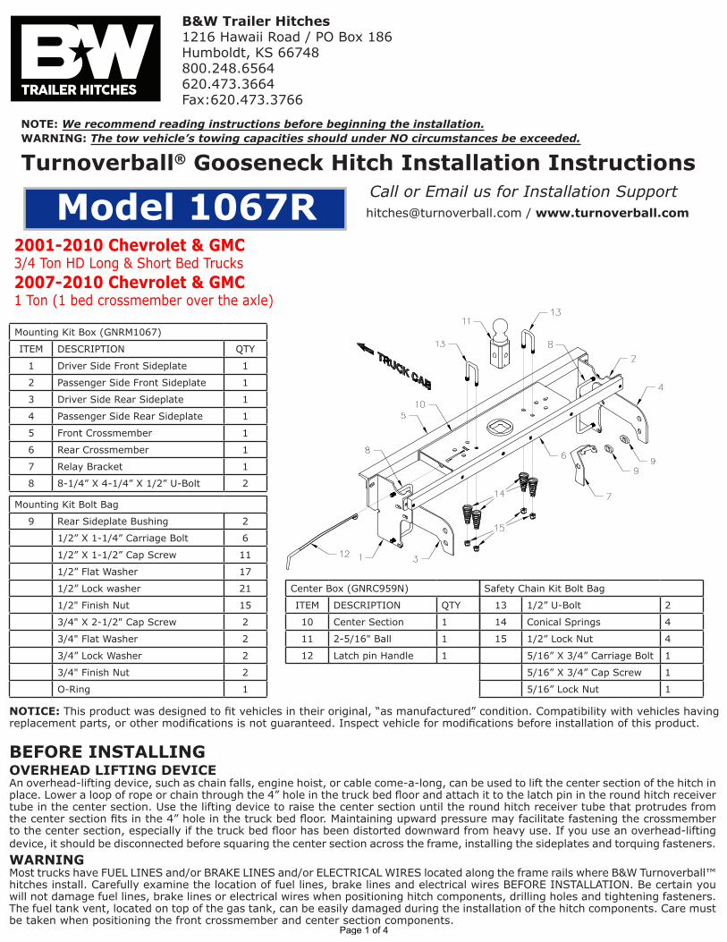
Mounting Kit Box (GNRM1067)
ITEM DESCRIPTION QTY
1 Driver Side Front Sideplate 1
2 Passenger Side Front Sideplate 1
3 Driver Side Rear Sideplate 1
4 Passenger Side Rear Sideplate 1
5 Front Crossmember 1
6 Rear Crossmember 1
7 Relay Bracket 1
8 8-1/4” X 4-1/4” X 1/2” U-Bolt 2
Mounting Kit Bolt Bag
9 Rear Sideplate Bushing 2
1/2” X 1-1/4” Carriage Bolt 6
1/2” X 1-1/2” Cap Screw 11
1/2” Flat Washer 17
1/2” Lock washer 21
1/2" Finish Nut 15
3/4" X 2-1/2" Cap Screw 2
3/4" Flat Washer 2
3/4” Lock Washer 2
3/4" Finish Nut 2
O-Ring 1
Center Box (GNRC959N)
ITEM DESCRIPTION QTY
10 Center Section 1
11 2-5/16" Ball 1
12 Latch pin Handle 1
Safety Chain Kit Bolt Bag
13 1/2” U-Bolt 2
14 Conical Springs 4
15 1/2” Lock Nut 4
5/16” X 3/4” Carriage Bolt 1
5/16” X 3/4” Cap Screw 1
5/16” Lock Nut 1
NOTICE: This product was designed to fit vehicles in their original, “as manufactured” condition. Compatibility with vehicles having replacement parts, or other modifications is not guaranteed. Inspect vehicle for modifications before installation of this product.
2001-2010 Chevrolet & GMC 3/4 Ton HD Long & Short Bed Trucks 2007-2010 Chevrolet & GMC1 Ton (1 bed crossmember over the axle)
Page 1 of 4
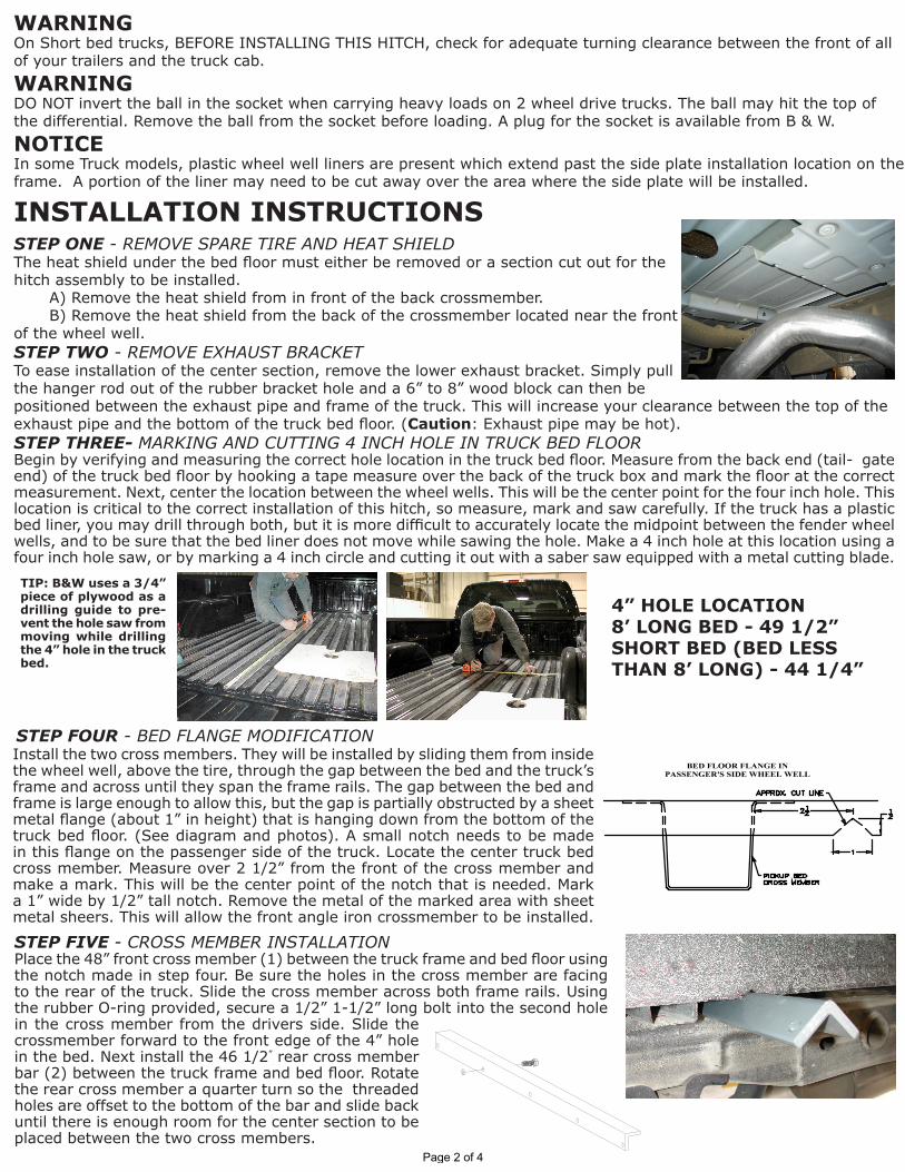
INSTALLATION INSTRUCTIONSSTEP ONE - REMOVE SPARE TIRE AND HEAT SHIELDThe heat shield under the bed floor must either be removed or a section cut out for the hitch assembly to be installed.
A) Remove the heat shield from in front of the back crossmember.B) Remove the heat shield from the back of the crossmember located near the front
of the wheel well.STEP TWO - REMOVE EXHAUST BRACKETTo ease installation of the center section, remove the lower exhaust bracket. Simply pull the hanger rod out of the rubber bracket hole and a 6” to 8” wood block can then be positioned between the exhaust pipe and frame of the truck. This will increase your clearance between the top of the exhaust pipe and the bottom of the truck bed floor. (Caution: Exhaust pipe may be hot).STEP THREE- MARKING AND CUTTING 4 INCH HOLE IN TRUCK BED FLOOR Begin by verifying and measuring the correct hole location in the truck bed floor. Measure from the back end (tail- gate end) of the truck bed floor by hooking a tape measure over the back of the truck box and mark the floor at the correct measurement. Next, center the location between the wheel wells. This will be the center point for the four inch hole. This location is critical to the correct installation of this hitch, so measure, mark and saw carefully. If the truck has a plastic bed liner, you may drill through both, but it is more difficult to accurately locate the midpoint between the fender wheel wells, and to be sure that the bed liner does not move while sawing the hole. Make a 4 inch hole at this location using a four inch hole saw, or by marking a 4 inch circle and cutting it out with a saber saw equipped with a metal cutting blade.
STEP FIVE - CROSS MEMBER INSTALLATIONPlace the 48” front cross member (1) between the truck frame and bed floor using the notch made in step four. Be sure the holes in the cross member are facing to the rear of the truck. Slide the cross member across both frame rails. Using the rubber O-ring provided, secure a 1/2” 1-1/2” long bolt into the second hole in the cross member from the drivers side. Slide the crossmember forward to the front edge of the 4” hole in the bed. Next install the 46 1/2” rear cross member bar (2) between the truck frame and bed floor. Rotate the rear cross member a quarter turn so the threaded holes are offset to the bottom of the bar and slide back until there is enough room for the center section to be placed between the two cross members.
TIP: B&W uses a 3/4” piece of plywood as a drilling guide to pre-vent the hole saw from moving while drilling the 4” hole in the truck bed.
STEP FOUR - BED FLANGE MODIFICATIONInstall the two cross members. They will be installed by sliding them from inside the wheel well, above the tire, through the gap between the bed and the truck’s frame and across until they span the frame rails. The gap between the bed and frame is large enough to allow this, but the gap is partially obstructed by a sheet metal flange (about 1” in height) that is hanging down from the bottom of the truck bed floor. (See diagram and photos). A small notch needs to be made in this flange on the passenger side of the truck. Locate the center truck bed cross member. Measure over 2 1/2” from the front of the cross member and make a mark. This will be the center point of the notch that is needed. Mark a 1” wide by 1/2” tall notch. Remove the metal of the marked area with sheet metal sheers. This will allow the front angle iron crossmember to be installed.
WARNINGOn Short bed trucks, BEFORE INSTALLING THIS HITCH, check for adequate turning clearance between the front of all of your trailers and the truck cab. WARNINGDO NOT invert the ball in the socket when carrying heavy loads on 2 wheel drive trucks. The ball may hit the top of the differential. Remove the ball from the socket before loading. A plug for the socket is available from B & W.NOTICEIn some Truck models, plastic wheel well liners are present which extend past the side plate installation location on the frame. A portion of the liner may need to be cut away over the area where the side plate will be installed.
4” HOLE LOCATION8’ LONG BED - 49 1/2”SHORT BED (BED LESS THAN 8’ LONG) - 44 1/4”
Page 2 of 4

STEP SEVEN - INSTALL SIDEPLATESBeginning in 2007 some models could be equipped with a factory installed trailer brake system. In this case, a relay will have to be relocated before the driver’s side sideplate can be installed. If the relay is present, there will be two bolt heads just above the large oval hole in the frame on the driver’s side. Loosen these bolts and slide relay to detach it from the frame.Beginning in 2009 the models with factory installed trailer braking systems have a wiring clip attached to the bottom of the frame on both sides of the truck just ahead of the axle. This bracket must be removed and relocated as shown.
Next install the sideplates. The driver’s sideplate is shown, with the bent flange to the front, and the large holes to the rear. Attach the two pieces of the sideplate together with ½” carriage bolts. The carriage bolts should be inserted into the square holes from the backside of the sideplates and fastened using a flat washer, lock washer and nut on each bolt. This can be completed before installation on the frame rail. Do not tighten at this time. Attach the flange on the sideplate to the front cross member using a ½ x 1 1/2 inch bolt, flat washer, lock washer and nut. Insert the bolt through the flange so that the nut when tightened is on the front side of the cross member. Next attach the rear bar to the sideplate ear threading a ½ inch by 1 ½ inch bolt with flat and lock washer into the bar.
STEP SIX - CENTER SECTION INSTALLATIONRaise the center section into position between the crossmembers and carefully move it above the fuel tank from beneath the truck. The receiver socket must be positioned to the rear with the latch pin release arm on the driver’s side. A lifting device, as described on Page 2 will help. The round hitch receiver that protrudes from the top of the center section must fit through the hole in the truck bed floor. Slide the front cross member back against the center section so that the bolt installed previously in the front cross member goes into the center section hole directly across from it. Line up the rest of the holes and attach the two members with 1/2” x 1 1/2” long bolts, lock washers, and nuts. Insert four 1/2” x 1 1/2” bolts, with flat and lock washer in-stalled, through the rear leg of the center section into the threaded holes of the rear crossmember and hand tighten.
Step 1:Locate the fuel valve.
Step 2:Disengage the locking pin.
Step 3:Slide fuel valve from bracket.
APPLICATION UPDATE:Beginning in 2004, a fuel valve mounted on the rear of the fuel tank on trucks equipped with gas engines, makes it more difficult to install the Turnoverball™ center section. This fuel valve can be easily removed and replaced to ease installation. Please follow the following instructions:
Step 4:Install Turnoverball™ Center Section.
Step 5: Replace fuel valve to bracket on fuel tank.
Remove wiring clip by pulling/prying out of frame.
Install side plate and insert clip into slot provided.
Side plate installed and clip in place.
Page 3 of 4

Copyright 2020B&W Custom Truck Beds, Inc. ALL RIGHTS RESERVED 1067R (pn 1067-1-R1021) 01 29 2020
STEP ELEVEN - INSTALL SAFETY CHAIN U-BOLTSTo install the safety chain brackets (8) it is necessary to drill four 1/2” holes through the truck bed floor. Drill the holes from beneath the truck, through the two holes located on each side and closest to the round receiver tube in the center section. This will locate the safety chain brackets (8) in the lowest point of the floor corrugation. Drop a U-bolt through each pair of holes from the topside of the truck bed floor. Place a spring and lock nut on each of the four legs. Tighten the lock nuts until 1/4” of thread extends through the lock nut.
STEP THIRTEEN - ENGAGE LATCH PINRetract the latch pin by pulling the handle all the way out until it stops and then rotating it clockwise. Place the 2-5/16” Ball (10) in the hitch receiver. Engage the latch pin by rotating the handle counter clockwise. Be certain the latch pin passes through the holes in the 2-5/16” Ball and fully engages through the hitch receiver. Finally, remove and lightly grease the four corners on the square base of the 2-5/16” Ball.
STEP TWELVE -REPLACE EXHAUST BRACKETReinstall the exhaust hanger brackets and the spare tire if removed during step 2.
When completed, tighten all the hardware in this order: Tighten the center section bolts to the cross members to 80 ft. lbs. and then make certain the hitch is square with the frame. Tighten the ¾” sideplate bolts to 120 ft lbs. and then tighten the frame clamping U-bolts. Tighten the U-bolts slowly; alternating between the top and bottom legs of the u-bolt until equally tightened to a maximum of 40 ft lbs. This torque may not be obtained without bend-ing the sideplate some. This is normal and will not hinder the function of the hitch. Next tighten the three carriage bolts on each sideplate to 60 ft. lbs and then tighten the sideplates to the front crossmembers to 80 ft. lbs.
STEP NINE - TIGHTEN HARDWARE
STEP EIGHTInstall the ½-inch x 8 ¼-inch U-bolt from inside the frame through the holes in the sideplate above and below the frame, use a lock washer and nut on each end of the U-bolt. Repeat this procedure on the pas-senger side of the truck with the other sideplate. (While installing the U-bolts around the frame use caution not to damage or pinch the wiring harness or brake lines).WITH FACTORY INSTALLED BRAKE CONTROL(if no factory install brake control is present continue to Step 8B) Step 8A: To relocate the brake relay; first insert a 3/4” X 2-1/2” bolt through the relay bracket. (see Step 1) Next slide a frame bushing onto the bolt. (see Step 2) The hole in the frame is oval shaped. B&W provides a frame bushing that converts the oval hole into a round hole. From the inside of the frame insert the bolt with bracket and bushing into the frame and sideplate making certain that the frame bushing is in the oval hole in the frame. Fasten the bracket with a 3/4” lock washer and nut on the outside of the side plate. (see Step 3) Next install the brake control relay by sliding its two bolts onto the relay bracket and tighten. (see Step 4) Repeat the bolting process on the passenger side minus the relay bracket. Continue to Step Nine.
WITHOUT FACTORY INSTALLED BRAKE CONTROL(if the truck is equipped with a factory installed brake control see Step 8A) Step 8B: Install the ¾-inch by 2 ½-inch bolt. Place a flat washer and frame insert on the 3/4” bolt and install the bolt from inside the frame through the lower rear hole in the side plate. Fasten with a lock washer and nut. (The hole in the frame is a slotted hole, and B&W provides an insert that converts the slotted hole to a 3/4” round hole).
LATCHPIN
TAB
IN−LINE
DRIVER SIDE
STEP 10 – INSTALL LATCH PIN RELEASE HANDLEWARNING: LATCH PIN WILL NOT FUNCTION PROPERLY IF HANDLE IS NOT INSTALLED CORRECTLY.Install the latch pin release handle by inserting it through the slot in the end of the center section on the driver’s side of the truck. Align the handle eyelet with the square hole in the latch pin so the handle is in line with the latch pin as shown. Secure the handle to the pin with the 5/16 X 3/4” carriage bolt and 5/16” locking flange nut as shown. Note: The included 5/16” cap screw can replace the carriage bolt if wrench access on the “cab side” of the handle is limited. Tighten the nut until it is secure. Do not over-tighten and deform the handle eyelet.
Page 4 of 4