model 2000sp operations manual - control...
TRANSCRIPT

11/2/2009 Page 1 of 58
MODEL 2000SP OPERATIONS MANUAL

11/2/2009 Page 2 of 58
Table of Contents
“What You Need to Know About the Model 2000SP" Section 1 … Model 2000SP Humidity Generator “General Comments And Overview Of The System” Section 2 … Procedure Used for Annual Calibration “Various Procedures Used For Annual Calibration And Validation” Section 3 … Helpful Hints When Performing Humidity Calibrations “Things To Watch Out For And Things To Avoid” Section 4 … System Inspection “When The System First Arrives” Section 5 … Preparation for Daily Operations and Calibration Procedure “A Good Practice To Get Into And How To Get It Done” Section 6 … Operating the M2000SP with the External Chamber “When You Need A Bigger Chamber” Section 7 … Operating Instructions with the External Chamber “How To Do It And What To Expect” Section 8 … Special Instructions When Operating at Temperatures >30°C “A Very Important Section … Be Sure To Read It” Section 9 … Data Communications Protocol “When You Have Time To Write Your Own Software” Section 10 … Optimum Operating Area of the Primary Chamber “The Best Places To Be For The Highest Overall Accuracy” Section 11 … Chamber Door Hole Location “When You Want To Drill Your Own” Section 12 … Procedure for Calibrating with the 2-Pressure System ”When You Can Do Your Own High Accuracy Calibration” Section 13 … The KPPRHT-1 Reference Instrument “It’s More Than A Reference … It’s Great For General Facility Operations”

11/2/2009 Page 3 of 58
Section 14 … Calibration Certificates “Primary Control Probe Calibration Data” Section 15 … System Calibration Support Documentation “Secondary Transfer Standard Calibration Data”

11/2/2009 Page 4 of 58
Model 2000SP Humidity Generator

11/2/2009 Page 5 of 58
Model 2000SP Humidity Generator
Introduction The Model 2000SP is a low cost, high accuracy alternative to RH calibrations that use 2-pressure or chilled-mirror technology and many times faster than procedures using saturated salts. The M2000SP incorporates advanced electronics and innovative approaches resulting in overall improvement in performance and reliability. With the external chamber, selected as an option, the system design provides a capability to perform the precise calibrations needed for critical process control applications, as well as the general purpose calibrations of chart recorders, data loggers and other devices that require less accuracy. The M2000SP, when used with the KPPRHT-1 reference instrument, can also be used for evaluations of dew point transmitters used in process and manufacturing control. Unlike larger systems, the Model 2000SP reaches equilibrium within minutes, thus completing a full range calibration in much shorter times. The flexibility of the system gives metrology laboratories a means for conducting continuous everyday, general purpose calibrations while larger, slower systems are used for other tasks that require extended calibration times. An advantage to the M2000SP is the mobility factor. It is lightweight and easily carried to the factory floor for direct loop calibrations of process control systems. Inserting the control transmitters directly into a known humidity/temperature, and adjusting to those values, provides a higher accuracy than individual component calibrations. The Model 2000SP is an accurate, general purpose humidity generator that provides the long term stability and repeatability of RH/T conditions to assure proper calibrations of instruments, transmitters, probes, recorders and data loggers.

11/2/2009 Page 6 of 58
Theory of Operation The system produces proper humidity values by continuously monitoring chamber conditions with a very accurate internal control probe. The probe measures both the RH and temperature, then sends this information back to microprocessor based controllers. Internally, there are 2 pumps connected to a closed-loop system, 1 pump for the dry air and the other for saturated air. Depending on the signals from the control probe the controllers will call for either “dry” or “wet” pump to be activated. The pumps respond accordingly, resulting in very precise, very fast response to maintain chamber stability. A high volume turbo-axial fan inside the chamber provides the uniformity of temperature and humidity, essential for multiple calibrations. System Description The M2000SP uses digital control for fast response and stability. The controllers are microprocessor based and are programmed for optimum performance for the application. A very accurate probe is installed inside the primary chamber to monitor the humidity and temperature. This probe is calibrated and adjusted to the readings of a 2-pressure generator, a system traceable to NIST technology. The primary chamber of the M2000SP will accommodate multiple probes for simultaneous calibrations. This improves the tracking between probes used for process control. Dimensions of the chamber are 150mm in diameter and 225mm in overall depth, with a useable depth of 150mm. A variety of chamber doors is available to accommodate probes of different diameters (5mm to 25mm). Doors are available for calibrating devices having probes with remote cables, i.e. chart recorders or RH/T transmitters. When an external chamber is mounted to the primary chamber the useable dimensions are 250mm (h) x 200mm (w) x 100mm (d). This allows testing and calibration of larger devices and larger quantities of small devices such as data loggers. Because the external probe is not insulated, and temperature effects are more dominant, this reduces the overall range for high accuracy data. However, the accuracy remains high when operating at or near ambient temperature conditions. Air within the primary chamber is circulated by a turbo-axial fan having a high CFM air flow. This air movement assures optimum uniformity of humidity and temperature within the primary chamber, and eliminates temperature stratification in the chamber. The saturator (wet air) and desiccant (dry air) are connected as closed loop systems that re-circulate the air inside the chamber on a demand, not continuous, basis. This results in longer periods between the replacement or regeneration of wet/dry components.

11/2/2009 Page 7 of 58
System Performance and Temperature Response Typically, once the chamber has reached temperature equilibrium and stability, the M2000SP will reach RH stability within 3-5 minutes for a 50% step change. Since it is always easier to create moisture, than to dry out the system, the response would be the 3 minutes for increasing RH and 5 minutes for decreasing RH, especially when trying to achieve 5-7% RH. Response time for temperature will vary depending on increasing or decreasing values. Measurements have shown that when starting at 23°C the rate for decreasing temperature is about 1°C/minute. While an increasing temperature will show 3°C/min. IT IS IMPORTANT TO REALIZE THAT EVEN THOUGH THE CONTROL PROBE IS RESPONDING AT THIS RATE THE CHAMBER IS MUCH SLOWER AND WILL BE DIFFERENT BY SEVERAL DEGREES. THIS IS THE REASON A WAITING PERIOD IS REQUIRED. It is recommended that when changing temperature by 5°C at least 20 minutes be given for chamber temperature stability and 30 minutes if possible. When changing the temperature more than 5°C then at least 30 minutes and 45 minutes if possible. Chamber Calibration of Humidity and Temperature Prior to installation all primary control probes are calibrated by an NVLAP Accredited laboratory using a 2-pressure system with an accuracy of ±0.5% RH or better. The probes are adjusted at the laboratory to the values of the primary standard, ±0.1% RH, at low, mid and high RH values using NIST traceable technology or recognized primary standard instrumentation. In order to achieve the highest accuracy, temperature is adjusted to ±0.05°C of the NVLAP standard before proceeding with the calibrating or adjusting of humidity. All calibration data and Certification with “AS LEFT” data is provided by the NVLAP Accredited lab. After the primary chamber probe has been installed a 4 port door is mounted to the chamber to check uniformity and accuracy against a secondary reference standard. The procedure is to install the reference in one of the ports to a depth of 125mm to 150mm and then set the temperature controller to the calibrated value to compare readings and make adjustments if needed. After temperature the procedure is followed for humidity. Final system adjustment is such that the humidity readings at the 3 calibrated RH values will agree to within ±0.2% RH and ±0.1°C at 23°C.

11/2/2009 Page 8 of 58
Operating the System with an External Reference To simplify re-calibration and every day operations it is recommended that whenever possible an external reference instrument be used to determine the final settings of humidity and temperature. Since most metrology labs have a portable reference device these can also be used with the M2000SP when calibrating other instruments. The external reference is inserted in an unused port of the chamber door and adjusting the controller set points until exact calibration values for RH and temperature are reached by comparing values to the reference instrument. KPPRHT-1 Reference Instrument The KPPRHT-1 is a versatile reference instrument that is calibrated for temperature and RH, and can also be calibrated for Dew Point. Typical DP accuracies compared to the NVLAP reference systems are ±0.2°C, often more than satisfactory for general checks of transmitter performance The KPPRHT-1 consists of an RH/T probe calibrated to the highest accuracy against the NVLAP standards and provided with full Certificates of Calibration.

11/2/2009 Page 9 of 58
IMPORTANT
PLEASE READ BEFORE OPERATING SYSTEM There are points regarding good measurement practices for general humidity calibration, as well as for the Model 2000SP, that we would like to present to make sure that you get the information that will give you a good understanding of the system as well as the factors to be considered in humidity calibrations. These points may also help answer some questions that you have. System Exposure to Cold Temperatures The Model 2000SP is a fast response system. However, The M2000SP may exhibit a slower initial response after exposure to cold temperatures. This could occur after being in a laboratory with lowered temperature over a weekend, or perhaps being in a vehicle left outside overnight. The reason for a slower response is because the water inside the saturator has cooled down. In order to create the higher RH values it is necessary to heat the saturator. If the water is cold then it will take longer to heat up. Typically, when the unit is first turned on, after a cold exposure, it may take 6-8 minutes to reach 95% RH. After the system has been heated it will take about 3-5 minutes to reach that value. Temperature Differential and Equilibrium Times The M2000SP response time is much faster than most devices under test. Therefore, although the M2000SP will indicate stability after 5 minutes this does not necessarily mean that the device under test is also at equilibrium. It is always good practice to wait at least 10 minutes to assure that both temperature and humidity are at equilibrium. This is especially important if the device under test has been at a temperature different than the temperature setting of the Model 2000. Waiting this extra time will assure the best results and accuracies. To facilitate measurements it is recommended that whenever possible the tests be done at room temperature, or very near to room temperature. Again, this is to reduce the time it will take for the devices under test to reach temperature equilibrium inside the chamber. For example, if the devices under test have been in an area which is at 25°C and the chamber is at 23°C it will take time for the devices to reach 23°C. However, if the chamber is set for 25°C then equilibrium will be rather quick.

11/2/2009 Page 10 of 58
Probe Depth Insertion When performing any RH calibration or adjustment it is always important that the probe or instrument under test be inserted well within the chamber. For the Model 2000SP the recommended depth is at 3-5 inches (7.5-12.5 cm) into the chamber. This is the area that will be least influenced by external temperature effects. If the probe is short and cannot be inserted into the chamber these are some suggestions. For probes that are connected to a cable use the split rubber plug. Open the split and insert the probe into the chamber. Place the cable with the probe about 3 inches beyond the door. Then open the split plug and wrap around the cable. Insert the rubber plug into the open hole of the door forming a seal For short probes without a cable it is best to set the controller temperature to the room temperature value, usually between 22° and 24°C. This eliminates any large temperature gradients. Important: You will note that throughout these recommended operating practices we will be placing an emphasis on making sure of temperature stability and equilibrium, without major gradients or fluctuations. These recommendations are not unique to the Model 2000SP. These are good practices when measuring humidity. Temperature stability is extremely important when the highest accuracy is to be reached. Control Probe and Reference Instrument Calibration The Model 2000SP is a very accurate RH generator. The control probe has been adjusted against readings of a 2-pressure system with NIST traceability. The adjustment has been done at an NVLAP accredited laboratory. In addition, the M2000SP system accuracy is verified against reference probes that have also been adjusted to readings of the 2-pressure generator. System output and controller display has been adjusted to within ± 0.2% RH and ±0.1°C of the references. User In-House Reference Instruments We have provided a system with a high accuracy. However, the operator always has the option to use an in-house reference for setting the RH and temperature values. In these instances the in-house reference is inserted into the chamber and the M2000SP is set to the corresponding RH and temperature values. The values can be recorded and these would be the set-point values a user would enter on the controllers for any future tests.

11/2/2009 Page 11 of 58
Operating with an External Chamber If an external chamber is also being used there are some important points to remember. The external chamber is not an insulated chamber, therefore there will be temperature gradients developed between the main inner chamber and the external chamber. Best results are obtained when the set point of the controller is at room temperature to reduce the effects of temperature gradients. When using the external chamber an independent reference is absolutely necessary. The control probe is inside the primary chamber monitoring the RH/T. This probe is only adjusting the values of the inner chamber as detected. The external chamber will most likely be at a different temperature. Therefore, the RH readings may not agree. This is the reason for the external reference. By inserting the reference instrument into the external chamber and observing the RH, the controller set points can be corrected for both RH and temperature. Under these conditions the high accuracy will be maintained over the measurement range of interest.

11/2/2009 Page 12 of 58
Procedures Used for Annual Calibration

11/2/2009 Page 13 of 58
Procedures That Can Be Used for Annual Calibration
There are several methods for the annual re-calibration. The user should determine which one is most suitable and convenient for their requirements. A. Return of Control Probe The primary control probe used in the Model 2000SP has been selected because it is ASIC based, which means the integrated electronics has been designed specifically for the application. All calibration data is stored in memory within the probe and travels with the probe. Thus, the user can remove the probe from the chamber; send it to the Accredited lab for calibration and adjustment, then plug the probe back in with the new calibration. When this procedure is used the customer can elect to purchase 2 calibrated probes. When one probe is sent in for calibration the second probe is used. Perhaps the second probe could have been sent in for calibration 2 weeks before. This probe is then inserted when the initial probe is removed and this means no loss of time waiting for a re-calibration cycle. B. Calibrated Reference Probe In this procedure the portable reference instrument (KPPRHT-1 or similar) is sent to the Accredited laboratory for a complete calibration at selected RH and temperature values, determined by the users requirements. As previously mentioned, Dew Point is another parameter that can be calibrated for General Purpose comparisons or calibrations. This approach has the advantage that all set points are based on the readings directly in the chamber at the points of calibration, thus providing the highest accuracy. It is strongly recommended that this approach be taken whenever possible. It simplifies the re-calibration procedure and since the chamber settings are directly related to the reference values, it eliminates any ambiguities about the measurement. An example of how it would be used follows. Using a reference probe, with certification data showing it has been calibrated to a high accuracy, eliminates any questions regarding the effects of electronics, linearity, temperature coefficient, etc... All controller settings are done against the reference values. Therefore, if a calibration point is 35% RH at 23°C the reference probe will continuously monitor the chamber conditions and the operator can adjust if necessary. If the chamber actually reads 35.4% RH on the reference then the RH set point can be reduced by 0.4% RH, the same for temperature.

11/2/2009 Page 14 of 58
Another advantage for the external reference is it allows the customer to use any calibration system. So, in the event that the main system has to go in for re-calibration or repair the back-up system, if provided, can be used to continue calibrations. Again, the reason is because the reference instrument provides the values of calibration, therefore accuracy is not in doubt. C. Complete System Check Using a 2-Pressure Generator This the most elaborate and expensive procedure and has been requested by some users. In this approach the entire system is sent to the Accredited laboratory and the entire system is calibrated. The procedure would be to remove the top cover of the M2000SP and remove the probe with the connecting cable from the chamber. The probe is then inserted into the 2-pressure system and the readings displayed on the controller are compared to readings of the 2-pressure unit. Adjustments are made after reviewing data. After readings are taken at 3 RH values it is determined if there is a bias, or if an adjustment should be made to improve the accuracy. Once the determination is made a “correction offset” can be entered into the controllers and another calibration is done to confirm the new readings. Instructions can also be given to the NVLAP laboratory to first do a calibration and adjustment on the probe itself. After making adjustments of the probe to exact readings of the 2-pressure system the probe is replaced in the connecting cable and the above procedure with direct insertion into the 2-pressure system would be followed. Calibration Certificates and Documentation The Certificate of Calibration for the primary control probe and the reference standard used for system verification are provided by the NVLAP Accredited laboratory. The “AS LEFT” data is included within the manual. Summary The M2000SP is a high accuracy system with operational specifications and performance characteristics equal to or better than other systems, many at a much higher price. The Model 2000SP offers simplicity of operation, fast response, high accuracy, low maintenance and affordability. Because of these characteristics the system also provides significantly greater productivity through faster turnaround times. The result is greater savings for everyday, routine humidity calibrations.

11/2/2009 Page 15 of 58
Helpful Hints When Performing RH Calibrations

11/2/2009 Page 16 of 58
Helpful Hints When Performing Humidity Calibrations 1. Temperature Effects When performing humidity calibrations or any type of humidity measurement the primary points to remember to get the highest accuracy are temperature, temperature, and temperature. If there are temperature fluctuations during the procedure or temperature differentials between the test chamber and instrument under test errors will be introduced, especially at high RH values. Temperature stability is important and should be emphasized. These are some practices that can be used to avoid potential problem areas and to improve the chances for obtaining a high accuracy humidity calibration.
A. Keep the calibration system in an area where the ambient temperature will not fluctuate dramatically. Avoid direct sunlight, HVAC vents and places where thermal differences could be present.
B. If the system has been in an environment where the temperature is very different
than the temperature of test allow the system to acclimate to the new temperature before starting the procedure.
C. When performing measurements that require step changes in temperature always
allow sufficient time for the chamber to stabilize to the new temperature. An example would be performing a test at 23°C then adjusting to 20°C. The control probe responds very quickly to indicate temperature stability; however, the external chamber needs time to stabilize to the new temperature. A rule of thumb would be to allow 5 minutes/°C when decreasing or increasing temperature particular attention should be paid when decreasing temperature because this will take longer to stabilize.
2. High Humidity Testing A common problem that occurs is condensation. This occurs when there are sudden temperature changes while the system is at high humidity >90%. This problem can be avoided by using these recommendations.
A. In general, keep the system at <50% RH when in a standby mode. This is a
preventative for condensation but also reduces the effects for hysteresis.

11/2/2009 Page 17 of 58
THE FOLLOWING ARE 2 IMPORTANT POINTS TO BE REMEMBERED
B. WHEN TESTING AT HIGH HUMIDITY ALWAYS BRING THE
SYSTEM TO TEMPERATURE STABILITY BEFORE INCREASING HUMIDITY.
C. DO NOT LOWER TEMPERATURE WHILE SYSTEM IS AT HIGH RH.
ALWAYS LOWER THE RH VALUE TO 35% RH OR LESS BEFORE DECREASING TEMPERATURE.
3. Instruments and Probes Being Tested
A. Highest accuracy is obtained when temperature differentials are minimized. It is an advantage to have the entire probe within the chamber as far as possible, preferably the entire unit.
B. When calibrating short probes try to keep the test temperature as close to ambient as possible, if acceptable. This reduces the temperature differences that occur and because the probe is close to the chamber door, also reduces the direct effect on the probe.
C. Transmitters or recorders with remote cables are best calibrated by inserting
the entire probe within the chamber and sealing the cable around the “split” connector grommets supplied with the system.
4. Calibration Recommendations Most manufacturers recommend that the first calibration be done at 33- 35% RH then at 75%-80% RH. This provides optimum linearity over the range. Because sensors are not linear at the low or high end manufacturers suggest that a “linearity check” be done by verifying at low and high RH. This should be done by starting at 10% RH and increasing in 20% steps to 90% or 95% RH. NOTE: The majority of instruments only allow for the 2 point adjustment. Some provide for a “low end” adjustment. There are none that recommend an adjustment at 90% or 95% RH. Therefore, these are “check” points not “adjustment” points.

11/2/2009 Page 18 of 58
System Inspection

11/2/2009 Page 19 of 58
System Inspection
Desiccant
A. When the desiccant is shipped separately from the system install the desiccant align the 2 tube extensions with the holes of the M2000SP and push firmly and evenly until fully inserted.
B. If desiccant is shipped within the system verify that desiccant is fully inserted by
pushing in firmly. Water Level (IMPORTANT) The M2000SP does not require a large quantity of water for operation. Keep the water level well below the mid point of the “lines” and just above the lower line. If no water is seen then fill syringes and fill water to correct level. One syringe of water is normally sufficient, but do not add more than 2. NOTE: Very often “air pockets” will form in the filling tube and this will cause an incorrect water level to be observed. To make sure the proper level is indicated lift the system and gently “rock the system” 2 or 3 times. NOTE: When the system is to be transported, as long as the water level is well below the mid-point or just above the “MIN” level there will be no problems. Problems will occur if the water level is exceeded by filling with several syringes. Again, not more than 2 syringes. Checking for Moisture within the System Prior to shipment the water level has been reduced to an amount that allows safe, trouble-free transportation. However, it is still possible that during shipment water has entered the chamber because of handling. THIS DOES NOT DAMAGE THE SYSTEM! For a quick check to determine if moisture is inside the chamber use this procedure.
1. Set RH @ 10% and temperature at 23°C. Turn on “Control” switch and observe level of RH after 5 minutes. If system is pumping on a steady basis, but the RH does not go below 20%, then moisture is inside the chamber.

11/2/2009 Page 20 of 58
2. Open door and wipe all surfaces with a paper towel. Then replace door, bring the RH to 10% and temperature to 23°C and repeat Step 1. If system does not reach 10% RH then there is embedded moisture within the chamber and a complete “drying out” process is required.
3. Refer to “Operating at High Temperatures and High Humidity” section for this procedure.
Temperature Equalization If the M2000SP has been in a cold environment for a long period of time there will be a slow response until temperature has been brought to room value. This often occurs when a system has been in a non-heated laboratory over a few days or when the system has been in an auto overnight during cold-months. A similar situation occurs during the hot summer months when a system may be in direct sunlight or left in an auto during the day. Allow sufficient time for the system to come into equilibrium with the ambient environment before beginning tests.

11/2/2009 Page 21 of 58
Preparation for Daily Operations and Calibration Procedure

11/2/2009 Page 22 of 58
Preparation for Daily Operations Throughout this manual you will find repeated emphasis on establishing temperature stability. It is provided as a reminder of its importance in humidity calibrations and accuracy. Introduction The M2000SP is an extremely simple system to operate, perhaps the easiest and most straight forward on the market. There are no conversion values to enter, no valves to adjust and no complex procedures. This is the procedure for humidity operation and calibration. Initial Start-Up for Daily Operations
1. Turn power ON and using the “UP” and “DOWN” arrows on the temperature controller set to 23°C.
2. Using the “UP” and “DOWN” arrows on the humidity controller set to 50% RH.
3. Turn CONTROL switch on and allow system to stabilize. For the initial daily
start-up wait at least 10 minutes.
4. Raise to 80% RH and allow operation at or near 80% RH for 3 minutes then raise to 92% RH and allow 5 minutes.
5. Lower to 50% RH (23°C) and prepare for daily calibrations.
Calibration Procedure Before making any controller adjustments select the chamber door that will accommodate the diameters of the devices that are to be tested and calibrated. Mount door to chamber and insert the probes under test into the primary system chamber, or into the external chamber if that is in use. Then proceed as follows:
1. Set temperature to required value, (i.e. 23°C). Wait at least 10 minutes. Note: System will only read in °C, therefore if °F is needed a conversion is required.
NOTE: If an external reference is being used insert reference probe into chamber to verify temperature is correct. Adjust temperature if necessary. Wait for stabilization (at least 5 minutes).

11/2/2009 Page 23 of 58
2. Set humidity to 50% RH and allow at least 10 minutes for both temperature and humidity stabilization.
3. Set humidity to required value (i.e. 35% RH) and wait 5 minutes (minimum for
RH equilibrium.
NOTE: If using an external reference instrument compare readings with chamber readings. Make necessary adjustments on the controllers for correct conditions.
4. Make necessary adjustments on the instruments always adjusting temperature
before proceeding to humidity.
NOTE: Depending on the quality of the temperature elements within the device under test, when temperature has been adjusted at this first point no further temperature adjustments should be needed.
5. Proceed to the next humidity value as specified by the manufacture.
NOTE: Most manufacturers will specify at least 2 calibration points, usually 33% or 35% RH and 75% or 80% RH. Some will even specify a 3rd point at the low end, either 5% or 11% RH.
6. Make necessary adjustments on the instruments and proceed to next humidity
value, if part of procedure.
NOTE: Some manufacturers will specify a 3rd calibration or adjustment point for better linearity at the low end. This will be either 5% RH or 11% RH, depending on probe.
If a 2-point calibration is all that is required then the calibration is finished after step 5. There might be some instances when the Operating Procedure will call for additional RH calibrations. In these instances follow the procedure outlined above, however, DO NOT MAKE ANY ADJUSTMENTS AT VALUES OTHER THAN THOSE SPECIFIED BY MANUFACTURER. When performing calibrations at values >80% RH temperatures >30°C refer to section “Procedure When Operating High Temperature and High Humidity”. System Operation Summary The M2000SP operation only requires entering the RH and temperature set point values and allowing sufficient time for these parameters to stabilize.

11/2/2009 Page 24 of 58
Care should always be taken not to do any adjustments before equilibrium. The M2000SP response time is much faster than the Unit Under Test (U.U.T.). The U.U.T. can easily take 15 minutes for RH and temperature stability because of the metal protective filters and metal construction of the probes. Once again, always allow time for full temperature stabilization of the chamber, even though controllers indicate stable condition.

11/2/2009 Page 25 of 58
Operating the M2000SP with an External Chamber

11/2/2009 Page 26 of 58
Operating the M2000SP with External Chamber Introduction The external chamber is designed to give more flexibility to the Model 2000SP by providing a larger chamber volume, in addition to the standard internal primary fast response chamber. These extended chambers enable larger instrumentation to be checked and verified. However, there is a significant reduction in the operating range for higher RH and temperature accuracy. Extended chambers have large clear plastic covers for easy visual observation of the recorder readings or readings of other digital devices. These covers are not insulated. This will have an effect on RH because of the temperature fluctuations that might occur. General Information The CHEXT series of extended chambers options are add-on cabinets that are attached directly to the main chamber and the enclosure. The M2000SP continues to function normally using the settings of the RH and Temperature controllers, and the precision of the internal control probe. However, there are 2 factors when using the external chamber. First, an external reference instrument must be used for final settings and second, because the external chamber is not insulated, the overall operating temperature range is limited to ambient, plus or minus a few degrees. The reference instrument can be any RH/T device that has been calibrated and adjusted by an Accredited NVLAP or A2LA laboratory to a high quality secondary or primary standard. Such an instrument would be the KPPRHT-1. The reference is inserted in the external chamber where it continuously measures conditions within the chamber. When the M2000SP is used with the external chamber all controller settings should be done against readings of a reference instrument. When using the reference instrument accuracy of the M2000SP system is dependent on the accuracy of this instrument, thus the reason for using a high quality, dependable reference. Since the external chamber is not insulated the recommended temperature range for testing should be within a few degrees of ambient. For best agreement between readings of the M2000SP RH controller display and readings of the reference instrument, the M2000SP temperature should be set at the same temperature measured inside the chamber by the reference.

11/2/2009 Page 27 of 58
Typical operation would be to install the recorder or devices that require calibration inside the external chamber and insert the reference. Set the temperature at 23°C and RH at 50%. Wait 10 minutes. Read temperature of the display and then set M2000SP temperature controller to that value. Let system stabilize and then set the RH to any value within the recommended range of the external chamber. In most instances stabilization should occur within 20-30 minutes for the initial RH value, and then 10-15 minutes for other RH values. Description of the Various Extended Chambers The Model 2000SP components have been selected for optimum performance for the volume of the internal chamber. When an Extended Chamber is used the volume is increased significantly. This increases the requirements of the RH generation system and subsequently reduces the RH operating range. The CHEXT 480 optional extended chambers with the performance range follows. Option CHEXT480 Primarily used to check small data loggers, small 6” circular chart recorders or small instruments with digital displays.
Typical Performance Characteristics Option Dimensions* Dimensions* RH Range Temp Differ**
(mm) (inches) CHEXT-480 250 X 200 X 150 10 X 8 X 6 20-90% ±1.0°C *Dimensions shown are Inside Height x Width x Depth. **Recommended maximum difference between the M2000SP temperature controller set-point and the reference instrument temperature display to be within ±1.5% of the reference RH displayed value. Results may vary between systems. For minimum difference always try to adjust the set-point temperature to be equal to the reference temperature.

11/2/2009 Page 28 of 58
Summary The capability to utilize an external chamber greatly enhances overall performance of the Model 2000SP. By having the right enclosure for the instruments the test time is significantly reduced when compared to systems that have larger chambers. This is done without loss of accuracy, since a reference standard is used. When the performance of the standard M2000SP is compared to other systems the advantages can be seen in accuracy, stabilization time, uniformity and low maintenance. Adding the CHEXT 480 enclosure for special instrumentation completes the advantages.

11/2/2009 Page 29 of 58
Operating Instructions with the External Chamber

11/2/2009 Page 30 of 58
Operating Instructions with External Chamber The following is the recommended procedure when using the Model 2000SP with an external chamber. Preparation
1. Remove standard door from primary chamber and mount the external chamber.
2. Insert KPPRHT-1, or other reference instrument, into side port of external chamber.
3. NOTE: Before inserting reference into side port observe ambient temperature.
4. Open door and place Units Under Test (U.U.T.) on chamber shelf, or if checking
probes, insert probes into ports of door. Procedure
1. Set temperature controller to same temperature displayed on reference instrument before inserting into side port.
NOTE: Use of the reference instrument increases the operating range to temperatures above and below ambient. Setting the temperature controller at ambient temperature gives best control and best correlation of the system to the reference readings.
2. Set RH controller to 50%. Turn “Control” switch on. Allow system to operate at
these conditions for 5 minutes. 3. Set temperature to the required calibration temperature, or if not a specific
temperature help system at ambient value.
4. Set RH controller to required RH calibration value and allow 5 minutes for stabilization.
5. After stabilization read display of RH controller and display of reference
instrument. If readings are same proceed to make necessary adjustments on the Units Under Test (U.U.T.).

11/2/2009 Page 31 of 58
6. If readings are different reset values on controllers as needed. Example of controller display reads 35.0% RH and reference display reads 34.4% RH the RH controller should be adjusted to 35.6% RH to increase reference reading by 0.6% RH.
NOTE: If there is no specific temperature and no specific RH then the Units Under Test can be adjusted to the reference readings.
7. After initial adjustment change RH to next value and proceed with calibration
requirements.
11/2/2009 Page 32 of 58
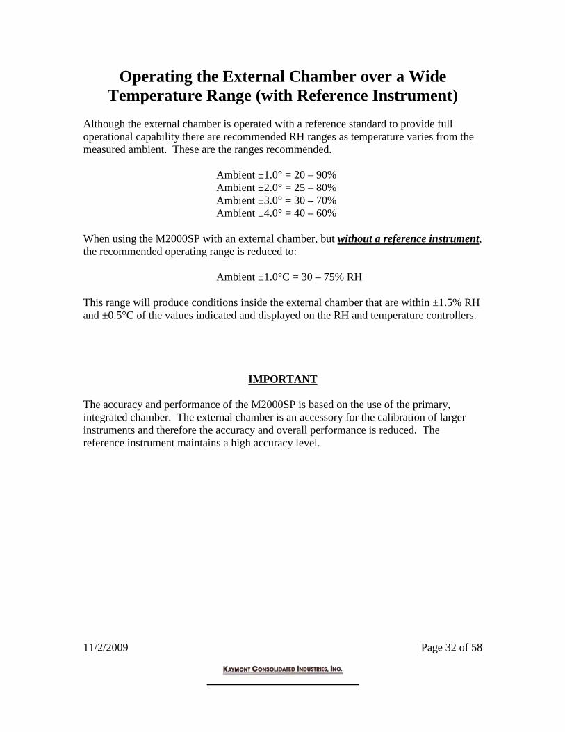
Operating the External Chamber over a Wide Temperature Range (with Reference Instrument)
Although the external chamber is operated with a reference standard to provide full operational capability there are recommended RH ranges as temperature varies from the measured ambient. These are the ranges recommended.
Ambient ±1.0° = 20 – 90% Ambient ±2.0° = 25 – 80% Ambient ±3.0° = 30 – 70% Ambient ±4.0° = 40 – 60%
When using the M2000SP with an external chamber, but without a reference instrument, the recommended operating range is reduced to: Ambient ±1.0°C = 30 – 75% RH This range will produce conditions inside the external chamber that are within ±1.5% RH and ±0.5°C of the values indicated and displayed on the RH and temperature controllers.
IMPORTANT The accuracy and performance of the M2000SP is based on the use of the primary, integrated chamber. The external chamber is an accessory for the calibration of larger instruments and therefore the accuracy and overall performance is reduced. The reference instrument maintains a high accuracy level.

11/2/2009 Page 33 of 58
Instructions When Operating at Temperatures >30°C

11/2/2009 Page 34 of 58
SPECIAL INSTRUCTIONS WHEN OPERATING AT TEMPERATURES >30°C
Introduction The M2000SP provides a “working” standard for facilities engineers and calibration/metrology labs. These areas are normally most interested in testing or calibrating within a temperature range of 20°-25°C and RH values 5-95%RH. However, there are instances when the M2000SP is to be operated at temperatures >30°C and at RH values >60%RH. These conditions require a recommended procedure in order to obtain the best results and to reduce or eliminate the potential for condensation. However, it should be pointed out that when performing these high temperature/high humidity tests, especially for stability calibrations at 40°C/75% RH, the likelihood of condensation forming on the chamber walls is very high. Procedure The following procedure is the recommended procedure for calibrating at 40°C/75% RH, but the same methodology should be used when performing a similar measurement at 30° or 35°C.
1. Insert Unit Under Test (U.U.T.) well inside the chamber, preferably 100mm to 125mm. Set the RH controller Set Point to 50% RH and the temperature Set Point to 30°C.
2. Wait 10 minutes. Raise to 35°C. Maintain 50% RH. 3. Wait 10 minutes. Raise to 40°C. Maintain 50%RH. 4. Wait 15 minutes to make sure all components are at 40°C. 5. Raise RH to 60% and wait 5 minutes. 6. Raise RH to 65% and wait 5 minutes. 7. Raise RH to 67% and wait 2 minutes. 8. Raise RH to 69% and wait 2 minutes.

11/2/2009 Page 35 of 58
9. Raise RH to 71% and wait 2 minutes 10. Raise RH to 73% and wait 2 minutes 11. Raise RH to 75% and wait 5 minutes
IMPORTANT: STOP! When tests are done DO NOT make any changes to RH or temperature. Read the following section before making changes.

11/2/2009 Page 36 of 58
Checking System for Condensation After Above Tests During the above tests condensation may have formed on the outer ring of the chamber door. This is because of the temperature differential between 40C and ambient. However, there may not be condensation on the chamber walls because of the slow increases that were made during the tests which gave time for all temperatures to equilibrate. Still there must be a check.
1. Lower the RH to 60%. Maintain 40C. Wait 5 minutes. 2. Lower the RH to 50%. Maintain 40C. Wait 5 minutes 3. Lower the RH to 40%. Maintain 40C. Wait 5 minutes 4. Lower the RH to 30%. Maintain 40C. Wait 5 minutes 5. Lower the RH to 20%. Maintain 40C. Wait 5 minutes
If the system has been able to reach the 20% RH then there is a good chance that condensation has not formed. However, proceed with the following to make sure.
6. Lower the RH to 10%. Maintain 40°C. Wait 10 minutes. 7. Lower temperature to 30°C@10% RH. Wait 10 minutes. 8. Lower temperature to 25°C@10% RH. Wait 10 minutes. 9. Lower temperature to 23°C@10% RH. Wait 5 minutes.
If the system begins to work extremely hard to get to the lower RH values it is most likely that condensation has formed. A “Dry Out” of the system is necessary. System Dry Out After Moisture Has Formed Inside Chamber The drying out of the chamber is simple and logical.
1. With chamber at 10% RH and 23°C open the chamber door and remove the inner air duct.
2. Wipe excess moisture from chamber walls and especially the rear of the chamber
with a paper towel.

11/2/2009 Page 37 of 58
3. Wipe excess water that has appeared around the front gasket. 4. Replace inner air duct. 5. Replace door and set chamber to 10% RH@ 23°C. 6. Turn system on and verify that system is controlling and that RH can be brought
down to 10% RH. If the system still does not go down to 10% RH then moisture has become trapped in the plates of the heat/cool device in the rear of the chamber. Follow this procedure.
1. Set system at 10% RH and 45°C and allow the system to “bake out”. If moisture is within the heat/cool plates the RH controller display will have remained in the 15% to 20% RH range throughout the lowering procedures.
2. After reaching 45°C the RH should begin to go down slowly at first then increase
in response as the drying out occurs. This will take about 10 minutes. 3. Lower the temperature to 23°C. System should be O.K.

11/2/2009 Page 38 of 58
Data Communications Protocol

11/2/2009 Page 39 of 58
Data Communications Protocol
The following is the protocol used with the Kaymont automated calibration sequence software. The monitor reads humidity and temperature based on the configurable sampling rate of the current automated procedure. The monitor writes humidity and temperature based on the configurable update rate of the current automated procedure. Description of the MODBUS message sent by the monitor:
To Read Humidity
Byte 0 0 X 20 ID of controller Byte 1 0 X 3 Read command Byte 2 0 X 0 High byte of register Byte 3 0 X 64 Low byte of register Byte 4 0 X 0 High byte of number of registers Byte 5 0 X 1 Low byte of number of registers Byte 6 0 X C3 Low byte of CRC Byte 7 0 X 64 High byte of CRC
To Read Temperature Byte 0 0 X 21 ID of controller Byte 1 0 X 3 Read command Byte 2 0 X 0 High byte of register Byte 3 0 X 64 Low byte of register Byte 4 0 X 0 High byte of number of registers Byte 5 0 X 1 Low byte of number of registers Byte 6 0 X C2 Low byte of CRC Byte 7 0 X B5 High byte of CRC

11/2/2009 Page 40 of 58
To Write Humidity Byte 0 0 X 20 ID of controller Byte 1 0 X 6 Command Byte 2 0 X 1 High byte of register Byte 3 0 X 2C Low byte of register Byte 4 High byte of value to register Byte 5 Low byte of value to register Byte 6 Low byte of CRC Byte 7 High byte of CRC
To Write Temperature
Byte 0 0 X 21 ID of controller Byte 1 0 X 6 Command Byte 2 0 X 1 High byte of register Byte 3 0 X 2C Low byte of register Byte 4 High byte of value to write to register Byte 5 Low byte of value to write to register Byte 6 Low byte of CRC Byte 7 High byte of CRC
Response to Read of Humidity Byte 0 0 X 20 ID of controller Byte 1 0 X 3 Command Byte 2 0 X 2 Number of bytes Byte 3 High byte of data Byte 4 Low byte of data Byte 5 Low byte of CRC Byte 6 High byte of CRC
Response to Read of Temperature Byte 0 0 X 21 ID of controller Byte 1 0 X 3 Command Byte 2 0 X 2 Number of bytes Byte 3 High byte of data Byte 4 Low byte of data Byte 5 Low byte of CRC Byte 6 High byte of CRC
Write response from device are echoes of write command.

11/2/2009 Page 41 of 58
Optimum Operating Area of the Primary Chamber

11/2/2009 Page 42 of 58
Operating Area Within the Chamber for
Optimum Accuracy During Calibration of
Probes and Instruments The Model 2000SP chamber has an overall depth of 9 inches. However, within the chamber are various electronic components needed to measure and control the chamber conditions. To utilize the advantages of the M2000SP and to provide an accurate calibration there is a procedure that should be followed. It is important that the devices under test be kept away from any areas where there could be any changes in RH due to temperature influences. This would be from internal and external sources. Therefore, there is a recommended area within the chamber where the effects of temperature are minimal. This area is shown in Figure 1. Any probe placed ahead of this area will be affected by the temperature of the heating/cooling section. Any probes inserted closer to the chamber door could be affected by outside ambient temperatures. The effects of temperature outside the recommended range will be minimal, and those areas can certainly be used for calibrating instruments that do not need high accuracy. It is always good practice to stay within this area that is least influenced by temperature from internal or external components.
Recommended Internal Calibration Area

11/2/2009 Page 43 of 58
Chamber Door Hole Location

11/2/2009 Page 44 of 58
Chamber Door Hole Location
A solid door can be provided with the system. In the event the customer wants to drill holes to accommodate probes of different sizes we are providing a drawing with the dimensions and locations for these holes. This drawing is for 2 ports or connectors.
Drawing No. 1 (2 Port Door)

11/2/2009 Page 45 of 58
Chamber Door Hole Location
Solid doors can be provided with the system. In the event the customer wants to drill holes to accommodate probes of different sizes we are providing a drawing with the dimensions and locations for these holes. This drawing is for 4 ports or connectors.
Drawing No. 2 (4 Port Door)

11/2/2009 Page 46 of 58
Procedure for Calibrating with the 2-Pressure System

11/2/2009 Page 47 of 58
Calibration Procedure Using 2-Pressure Generator System
Introduction For companies with 2-pressure systems it is possible to do a calibration of the control probe, the Model 2000SP system or both. When doing an internal calibration with the 2-pressure system high accuracy will be obtained by performing a 3 point calibration (2 RH and 1 temp). Better linearity and overall accuracy will be achieved with a 4 point (3 RH and 1 temp) procedure. This will require a KPPRHT-1 instrument with an extended cable to insure probe placement well inside the 2-pressure chamber. Regarding overall accuracy, the Model 2000 has been designed so that the effects of system electronics will be minimal on overall system accuracy. This means that after the control probe is calibrated and re-installed within the Model 2000SP chamber, maximum additional uncertainty will be on the order of ±0.2% RH and ±0.1°C. Refer to the section of the KPPRHT-1 for a description of the instrument. This will detail the additional capabilities of the unit and its use for calibration, as well as general purpose operation and maintenance measurements. Please use this information to determine which of the following calibration procedures is best suited for your operational needs. Control Probe Calibration When using the KPPRHT-1 for calibration, calibration adjustments can only be made at 35%, 80% and 10% RH in this RH sequence. All other readings are to be recorded and used if the user wants to develop a “Calibration Curve”.
DO NOT TURN POWER ON AT THIS TIME.
1. Remove the inner air flow duct.
2. Remove control probe by aligning the 4 “dots” and pulling out the probe.
3. Install the control probe into the KPPRHT-1 calibration cable by aligning the “dots”, pushing in the probe and then turning the locking collar.

11/2/2009 Page 48 of 58
4. Insert the probe and cable well into the 2-pressure access port and sealing the opening and cable. Follow this sequence.
5. Set 2-pressure generator @ 35% RH and 23°C. Allow system to stabilize for
1 hour. Adjust control probe to 2-pressure temperature (23°C) by following KPPRHT-1 instructions.
6. System is now stabilized and adjusted at 23°C. System is also stabilized at
35% RH. Adjust control probe to 2-pressure reading (35%) following KPPRHT-1 instructions.
7. Set 2-pressure generator to 80% RH @ 23°C. Allow system to stabilize for 1
hour. Adjust control probe to 2-pressure reading following the KPPRHT-1 instructions.
8. Set 2-pressure generator to 10% RH @ 23°C. Allow system to stabilize for
1.5 hours (decreasing RH requires more time to dry the chamber). Adjust control probe to 2-pressure reading following KPPRHT-1 instructions.
9. Set 2-pressure generator to 95% RH @ 23°C. Allow system to stabilize for 1
hour. DO NOT MAKE ANY ADJUSTMENT OF CONTROL PROBE. THIS IS A LINEARITY CHECK ONLY. RECORD DATA.
The control probe can also be calibrated. And can be replaced into the system by first removing probe and cable from the 2-pressure access port, then removing the probe and replacing inside the primary chamber of the M2000SP. A. Align “dots”. Push-in probe. Twist locking collar. Replace inner air duct. Direct System Calibration When using the 2-pressure generator to calibrate the M2000SP as a system there is no direct adjustment of the calibration points. Any adjustment to be done on the system is done by entering a “correction offset” through the controllers of the M2000SP and this can only be done at 1 temperature and 1 RH value. This is a longer calibration because the readings and settings must be done 2 times. The first test is done at 3 RH values and 1 temperature to determine the necessary offset. The second calibration is to re-check final system readings after the offset has been entered.
1. Remove the top cover from the M2000SP. Loosen cable grip and remove control probe from chamber. DO NOT REMOVE CONTROL PROBE FROM SYSTEM CABLE WITH WHITE CONNECTOR.

11/2/2009 Page 49 of 58
2. Insert the entire control probe with cable as far into the 2-pressure generator
as possible.
Note: Because of the cable length it may be necessary to build up a platform to hold the M2000SP and allow direct entry into the access port.
3. Set 2-pressure generator to 35% RH @ 23°C and allow 1 hour for the system
to stabilize. RECORD RH AND TEMPERATURE VALUES. 4. Set 2-pressure generator to 80% RH @ 23°C and allow 1 hour for the system
to stabilize. RECORD RH AND TEMPERATURE VALUES.
5. Set 2-pressure generator to 10% RH @ 23°C and allow 1 hour for the system to stabilize. RECORD RH AND TEMPERATURE VALUES.
Review the RH and temperature readings and determine if there is a “bias” (offset in one direction + or -) or if 1 value has a greater difference than another value. In the case of a “bias” the readings will differ in one direction. Therefore, if all readings are on the + side total the offset and then get the average and make the correction. For example, readings are 35.2%, 80.4% and 10.3%. The total offset is +0.9% with the average of the 3 readings +0.3% RH. A correction offset of +0.3 would be entered into the controller. The same procedure would be for temperature. When readings are varied + and – then a determination must be made how much a correction should be. For example, readings are 35.4%, 79.8% and 10.2%. The largest correction would be at 35%, if at all needed. A correction of +0.1% RH at 35% would now alter readings to result in 35.3%, 79.7% and 10.1% RH. CONSULT FACTORY FOR INSTRUCTIONS ON HOW TO ENTER CORRECTION VALUES VIA THE HUMIDITY AND TEMPERATURE CONTROLLERS. RH Cycle Test to Verify Linearity Over Range After entering the offset values for temperature and RH it is necessary for the user to once again cycle the M2000SP through the same calibration points to confirm the overall linearity of the system and that the right corrections have been entered.

11/2/2009 Page 50 of 58
Summary of Calibration with 2 Pressure Generator The availability of the 2-pressure generator will assure the highest accuracy over the range, therefore the best procedure would be a combination of the above. Once this accuracy has been transferred to the Model 2000 the calibrations of other instrumentation will be accurate, with a significantly faster procedure.

11/2/2009 Page 51 of 58
The KPPRHT-1 Reference Instrument

11/2/2009 Page 52 of 58
Operating the KPPRHT-1 as a Reference Instrument
When used as a reference instrument the KPPRHT-1 is supplied with a remote cable. This allows the probe to be inserted well into the chamber away from outside temperature influences. The cable also serves as a solid extension so that the cable grip has a good sealing surface. NOTE: TEMPERATURE AND DEW POINT ARE DISPLAYED IN °C BUT THIS CAN BE CHANGED BY FOLLOWING THE PROCEDURE WRITTEN BELOW. This is the basic operation of the system when used in the reference mode for RH/T.
1. Connect the reference probe to the cable by aligning all dots, then pushing in the probe. When firmly seated twist the collar until the middle 2 dots are offset. This locks the probe in place.
2. There are 3 connectors on the KPPRHT-1. One is for RS232 (not used with
this application) and the other 2 are for the probe/cable combination. For the reference probe application, connect the probe/cable to the connector that requires the cable to be screwed into the instrument.
3. Turn KPPRHT-1 on by pressing the RED button. If there are no digits
displayed the probe select is in the wrong position. Press either “arrow” and the RH and temperature should be displayed.
4. To maintain these readings press the RED button. “HOLD” will be
displayed.
5. To shut off instrument press the RED button and hold for 3-5 seconds. This is the basic operation of the system for dew point measurement.
1. Follow steps 1, 2 and 3 above.
2. When RH and temperature is displayed press MENU. CALCULATE will be displayed. Then press ENTER and Dew Point will be displayed.
3. Press the RED button and the display will go back to RH and temperature.

11/2/2009 Page 53 of 58
This is the basic procedure to change from °C to °F.
1. Follow steps 1, 2 and 3 in the above RH/T procedure.
2. When RH and temperature is displayed press MENU. CALCULATE will be displayed. Press DOWN arrow until SETTINGS is displayed.
3. Press ENTER. TREND will be displayed.
4. Press DOWN arrow until UNITS is displayed.
5. Press ENTER and METRIC will be displayed.
6. Press DOWN arrow until ENGLISH is displayed.
7. Press ENTER and SAVE? will be displayed.
8. Press ENTER. Temperature and Dew Point will be displayed in °F.
9. Press RED button, hold for 3-5 seconds and instrument will shut down.

11/2/2009 Page 54 of 58
The KPPRHT-1 Reference Instrument
Basic Description of KPPRHT-1 Instrument The KPPRHT-1 is a portable indicator that provides a direct reading of humidity and temperature, this can provide a variety of calculated parameters based on the RH/T data. In addition to being the calibration instrument for the Model 2000SP, the KPPRHT-1 is an excellent device for providing spot check measurement of HVAC and manufacturing processes. The KPPRHT-1 has the following Performance Specifications and will display the data indicated in the specifications.
Model KPPRHT-1 Probe Specifications:
Humidity Sensor Solid State Capacitance Type Temperature Sensor Pt100ohm RTD Humidity Accuracy @ 23°C ±1.0% RH, 4 Point Calibration Temperature Accuracy ±0.2°C Measured Parameters Relative Humidity 0-100% RH Temperature 0-60°C Calculated Parameters Dew Point/Frost Point Displayed in °C or °F Wet Bulb Temperature Displayed in °C or °F Enthalpy Displayed in J/g or BTU/lb Absolute Humidity Displayed in g/m3 or gr/cuft Specific Humidity Displayed in g/kg or gr/lb Mixing Ratio Displayed in g/kg or gr/lb Vapor Concentration at Sat Displayed in g/m3 or gr/cuft Partial Press of Water Vapor Displayed in hPa, PSI or In Hg Sat Pressure of Water Vapor Displayed in hPa, PSI or In Hg System Accuracy @ 23°C Relative Humidity ±1.0%RH Temperature ±0.2°C Display Type Alphanumerical LC Battery Status Automatic Indication Operating Power 9V Alkaline Battery Operating Limits at Electronics 0-95% RH (non-condensing)
– 10° … 50°C Housing Material ABS Plastic Weight 200g

11/2/2009 Page 55 of 58
Using the KPPRHT-1 for General Plant Measurements

11/2/2009 Page 56 of 58
Calibration Certificates

11/2/2009 Page 57 of 58
System Calibration Support Documentation (Should have been shipped with your unit)

11/2/2009 Page 58 of 58