model “251cde” - automated conveyor s
TRANSCRIPT
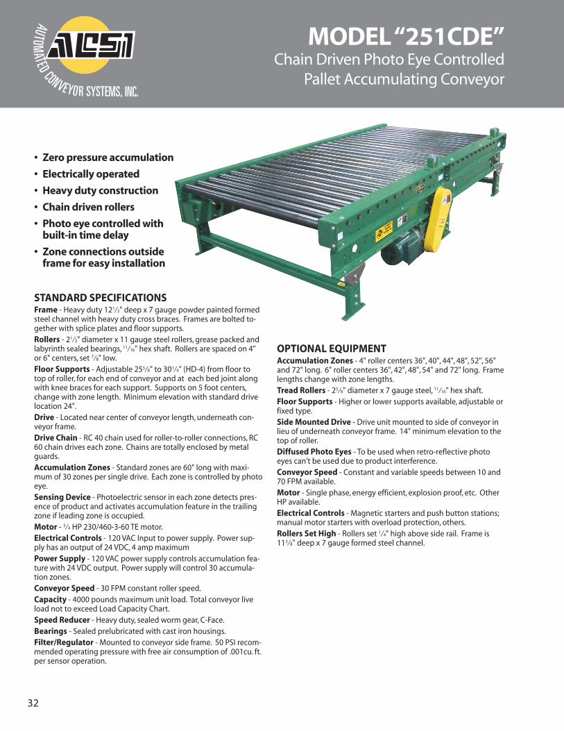
MODEL “251CDE”Chain Driven Photo Eye Controlled
Pallet Accumulating Conveyor
STANDARD SPECIFICATIONSFrame - Heavy duty 121⁄2" deep x 7 gauge powder painted formedsteel channel with heavy duty cross braces. Frames are bolted to-gether with splice plates and floor supports.Rollers - 21⁄2" diameter x 11 gauge steel rollers, grease packed andlabyrinth sealed bearings, 11⁄16" hex shaft. Rollers are spaced on 4"or 6" centers, set 7⁄8" low.Floor Supports - Adjustable 255⁄8" to 301⁄4" (HD-4) from floor totop of roller, for each end of conveyor and at each bed joint alongwith knee braces for each support. Supports on 5 foot centers,change with zone length. Minimum elevation with standard drivelocation 24".Drive - Located near center of conveyor length, underneath con-veyor frame.Drive Chain - RC 40 chain used for roller-to-roller connections, RC60 chain drives each zone. Chains are totally enclosed by metalguards.Accumulation Zones - Standard zones are 60" long with maxi-mum of 30 zones per single drive. Each zone is controlled by photoeye.Sensing Device - Photoelectric sensor in each zone detects pres-ence of product and activates accumulation feature in the trailingzone if leading zone is occupied.Motor - 3⁄4 HP 230/460-3-60 TE motor.Electrical Controls - 120 VAC Input to power supply. Power sup-ply has an output of 24 VDC, 4 amp maximum Power Supply - 120 VAC power supply controls accumulation fea-ture with 24 VDC output. Power supply will control 30 accumula-tion zones.Conveyor Speed - 30 FPM constant roller speed.Capacity - 4000 pounds maximum unit load. Total conveyor liveload not to exceed Load Capacity Chart. Speed Reducer - Heavy duty, sealed worm gear, C-Face.Bearings - Sealed prelubricated with cast iron housings.Filter/Regulator - Mounted to conveyor side frame. 50 PSI recom-mended operating pressure with free air consumption of .001cu. ft.per sensor operation.
OPTIONAL EQUIPMENTAccumulation Zones - 4" roller centers 36", 40", 44", 48", 52", 56"and 72" long. 6" roller centers 36", 42", 48", 54" and 72" long. Framelengths change with zone lengths.Tread Rollers - 25⁄8" diameter x 7 gauge steel, 11⁄16" hex shaft.Floor Supports - Higher or lower supports available, adjustable orfixed type.Side Mounted Drive - Drive unit mounted to side of conveyor inlieu of underneath conveyor frame. 14" minimum elevation to thetop of roller.Diffused Photo Eyes - To be used when retro-reflective photoeyes can't be used due to product interference. Conveyor Speed - Constant and variable speeds between 10 and70 FPM available.Motor - Single phase, energy efficient, explosion proof, etc. OtherHP available.Electrical Controls - Magnetic starters and push button stations;manual motor starters with overload protection, others. Rollers Set High - Rollers set 1⁄4" high above side rail. Frame is113⁄8" deep x 7 gauge formed steel channel.
• Zero pressure accumulation
• Electrically operated
• Heavy duty construction
• Chain driven rollers
• Photo eye controlled withbuilt-in time delay
• Zone connections outsideframe for easy installation
32

OPERATIONAL SEQUENCE1) Model “251CDE” is loaded at the infeed end of conveyor.The first load travels the entire length of the conveyor toZone #1. If the photoelectric sensor in Zone #1 has beenactivated by an external signal (normally open contact,not supplied) the product will stop in Zone #1.
2) The second load travels the length of the conveyor until itreaches Zone #2. If Zone #1 is occupied, the second loadwill stop in Zone #2. Load #3 will stop in Zone #3 and con-tinue to accumulate at “zero pressure”until fully loaded.
3) To unload, an external signal (normally open contact, not supplied) to the photoelectric sensorin Zone #1 will release the accumulation feature and allow the product in Zone #1 to leave theconveyor. The load in Zone #2 will not advance into Zone #1until the load in Zone #1 has com-pletely cleared Zone #1’s photoelectric sensor; the third load will not advance into Zone #2 untilthe second load clears the photoelectric sensor in Zone #2. Once the first load clears the photo-electric sensor in Zone #1, the external signal must be restored to Zone #1’s photoelectric sensorfor the accumulation process to continue.
MODEL “251CDE”
4.87
5" 6.5"
22.5
"
STANDARD: ROLLERS SET LOW,RETRO-REFLECTIVE PHOTO EYE,
& UNDER MOUNT DRIVE.
OVERALL WIDTH
BETWEEN FRAMES
CONVEYING SURFACE
DIRECTION OF FLOW ZONE LENGTH
ROLLER CENTERSPHOTO EYE
#60 CHAIN
#40 CHAIN
CHAIN TAKE-UP
25.6
25" -
30.
25"
TOP
OF
RAIL
6"6.
5"
0.87
5" L
OW
OPTIONAL: ROLLERS SET HIGH,DIFFUSED PHOTO EYE,
SIDE MOUNT DRIVE.
13.7
5"
Load Capacity Charts
Conveying Surface 34" 40" 46" 52" 58"Bed Between Frame Width 37" 43" 49" 55" 61"
LengthOverall Frame Width 41" 47" 53" 59" 65"
Rollers on 4" Centers 10' 1378 1483 1588 1693 179915' 1964 2117 2270 2423 2577
20' 2549 2570 2951 3152 3354
25' Weights 3135 3384 3633 3882 4132
30' (lbs.) 3720 4017 4314 4611 4909
40' 4891 5284 5677 6070 6464
50' 6062 6551 7040 7529 8019
60' 7233 7818 8403 8988 9574
70' 8404 9085 9766 10447 11129
80' 9575 10352 11129 11906 12684
90' 10746 11619 12492 13365 14239
100' 11917 12886 13855 14824 15794
Note: Overall lengths in chart are for 60" zones. Other zone lengths will affect overall length.
NOTE- Minimum elevation with 3⁄4 H.P. motor drive mounted un-derneath conveyor is 24".Capacities based on 50% of load moving at same time.
Accumulated MovingConveyor Speed @ 30 FPM Conveyor Speed @ 30 FPM
HP Total Load (lbs.) HP Total Load (lbs.)Up to 50’ Up to 100’ Up to 50' Up to100'
3⁄4 12000 7500 3⁄4 6000 37501 18000 13000 1 9000 650011⁄2 30000 25000 11⁄2 15000 125002 42000 37000 2 21000 18500
PHOTO EYEZONE 3
PHOTO EYEZONE 2
PHOTO EYEZONE 1
LOAD#3
LOAD#2
LOAD#1
PHOTO EYEZONE 3
PHOTO EYEZONE 2
PHOTO EYEZONE 1
LOAD#3
LOAD#2
LOAD#1
FLOWUNLOADING
GAP
FLOWLOADING
33