model 352-101, 352-102, 352-103, and 352-104 division 1 ... · division 1 smart hazardous area...
TRANSCRIPT
Pub. 42004-455B
GAI-TRONICS 3030 KUTZTOWN RD. READING, PA 19605 USA 610-777-1374 800-492-1212 Fax: 610-796-5954
VISIT WWW.GAI-TRONICS.COM FOR PRODUCT LITERATURE AND MANUALS
G A I - T R O N I C S ® A H U B B E L L C O M P A N Y
Model 352-101, 352-102, 352-103, and 352-104 Division 1 SMART Hazardous Area Telephones
Confidentiality Notice This manual is provided solely as an operational, installation, and maintenance guide and contains sensitive business and technical information that is confidential and proprietary to GAI-Tronics. GAI-Tronics retains all intellectual property and other rights in or to the information contained herein, and such information may only be used in connection with the operation of your GAI-Tronics product or system. This manual may not be disclosed in any form, in whole or in part, directly or indirectly, to any third party.
General Information GAI-Tronics’ Class I, Division 1 SMART Hazardous Area Telephones are constructed of cast aluminum and are weatherproof and corrosion resistant. They combine standard telephone operation with GAI-Tronics’ Self-Monitoring and Reporting Telephone (SMART) technology to provide optimum performance and flexibility.
When used with the GAI-Tronics’ Telephone Management Application (TMA) each telephone is monitored and the status is reported. For complete details, please refer to the on-line help included with TMA.
This manual applies to the following models:
Model 352-101 Division 1 SMART Hazardous AreaTelephone
Model 352-102 Division 1 SMART Hazardous AreaTelephone with Ring Relay
Model 352-103 Division 1 SMART Hazardous AreaTelephone with Headset
Model 352-104 Division 1 SMART Hazardous Area Telephone with Ring Relay and Headset
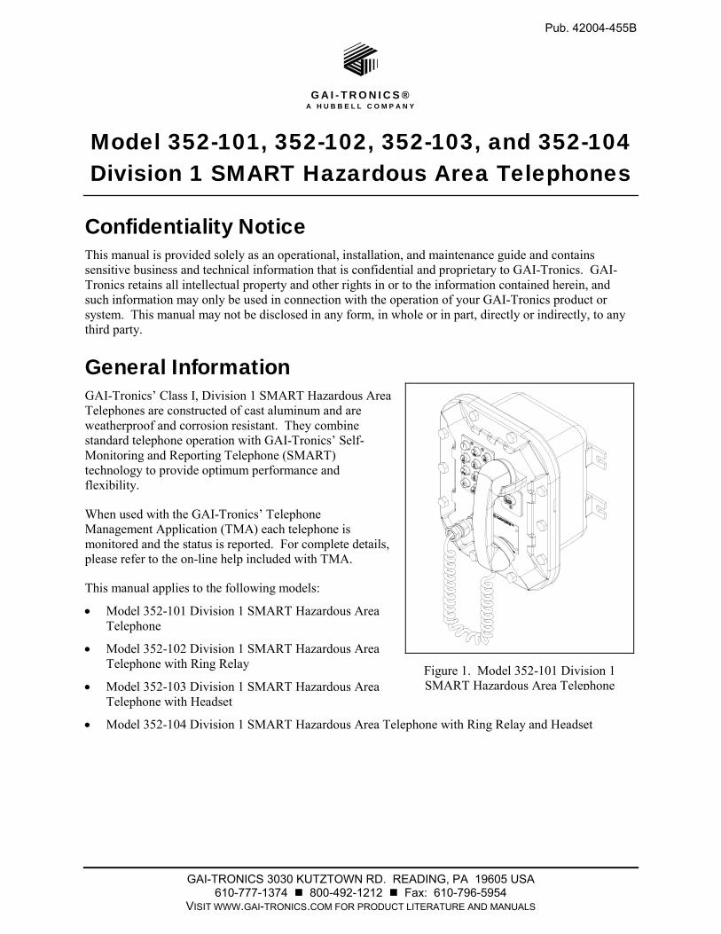
Figure 1. Model 352-101 Division 1 SMART Hazardous Area Telephone

Pub. 42004-455B Model 352-101, 352-102, 352-103, & 352-104 Div. 1 SMART Hazardous Area Telephones Page 2 of 17
f:\standard ioms - current release\42004 instr. manuals\42004-455b.doc 02/13
The GAI-Tronics SMART Telephone product line provides the flexibility to address a diverse range of applications. A wide variety of functions can be achieved by altering the configuration data stored in the telephone’s non-volatile memory. These configuration options include:
Call progress detection, control, and call logging
Auto-calling, auto-answering, and auto-dialing facilities
Function inhibiting (e.g. tone pad and manual keypad dialing)
Maximum call duration
These functions are initially programmed during manufacturing and testing. After installation, they can be programmed remotely via DTMF data call.
All SMART Telephones are line-powered and can be connected to the 24 V dc or 48 V dc analog station port of Private Branch Exchange (PBX), Private Automatic Branch Exchange (PABX) or KSU.
Connection may not be made to pay telephone extensions or shared service (party) lines.
TMA users can schedule auto-dial maintenance calls to alert maintenance personnel of any unusual sensor or fault conditions that exist. SMART Telephones can also be programmed to generate an auto-dial maintenance call when certain sensor events are discovered. Access to the SMART Telephone’s maintenance mode is restricted through the use of the maintenance access PIN. The maintenance access PIN should be distributed only to trained maintenance personnel.
Installation Installation Guidelines These enclosures must be installed by trained, qualified and competent personnel. Installation must comply with state and national regulations, as well as safety practices for this type of equipment.
CAUTION Do not install this equipment in hazardous areas other than those indicatedon the approval listing in the “Specifications” section of this manual. Such installation may cause a safety hazard and consequent injury or property damage.
The mounting location must be flat and provide proper clearance, rigidity and strength to support the enclosure and all contained devices.
WARNING Securely fasten the enclosure to the mounting location, using 3/8-inch diameter steel mounting bolts and washers, or washer head bolts.
WARNING Do not disconnect equipment while energized. Insure proper grounding to protective earthing.
WARNING The front cover is not hinged to the rear enclosure. When the cover bolts are removed, the cover must be adequately supported.
ATTENTION Installation should be performed by qualified personnel and only in accordance with the National Electrical Code or applicable local codes.

Pub. 42004-455B Model 352-101, 352-102, 352-103, & 352-104 Div. 1 SMART Hazardous Area Telephones Page 3 of 17
f:\standard ioms - current release\42004 instr. manuals\42004-455b.doc 02/13
Inspect and clean the machined flange flame joint surfaces of both the cover and box. Surfaces must be smooth, free of nicks, scratches, dirt or any foreign particle build-up that would prevent a proper seal. Surfaces must seat fully against each other to provide a proper explosion-proof joint. Clean surfaces by wiping with a clean lint-free cloth.
Apply a light coat of Killark “LUBG” lubricant to flange surfaces and close the cover. Install and tighten all cover bolts to 30 ft-lbs. Make certain no cover bolts are omitted. Use only those bolts supplied with the enclosure.
When installing any GAI-Tronics telephone equipment, please adhere to the following guidelines to ensure the safety of all personnel:
Electrostatic Discharge (ESD) Protection: Your telephone has an earth ground terminal provision.Ensure that it is connected to ground in accordance with all local safety regulations and the NationalElectrical Code (NEC). Grounding must be ensured for safe and stable communications. Do not uselong and coiled ground wires. Please note proper grounding does not eliminate the need for lightningprotection for the telephone or the telephone system.
NEVER install telephone during a lightning storm.
Install a UL Listed lightning arrestor on any telephone installed where the telephone or telephonecable is at risk of being exposed to lightning strikes. The lightning arrestor must be installed as closeto the telephone as possible in a non-hazardous environment to maximize the protection. Thelightning arrestor must not be installed within the enclosure supplied with the telephone.
NEVER install telephone jacks in wet locations unless the jack is specifically designed for wetlocations.
NEVER touch uninsulated telephone wires or terminals unless the telephone line has beendisconnected at the network interface.
USE CAUTION when installing or modifying telephone lines.
GAI-Tronics’ SMART Telephones are designed to operate on telephone lines as detailed in the “General Information” section of this manual. The telephones are designed to operate with one telephone per line. If telephones are operated in parallel or party-line configuration you may experience sporadic telephone operation, difficulties with programming, or premature disconnection of calls. Additionally, if special features, e.g. voice mail, call waiting, etc, are not disabled, the telephone may not function.

Pub. 42004-455B Model 352-101, 352-102, 352-103, & 352-104 Div. 1 SMART Hazardous Area Telephones Page 4 of 17
f:\standard ioms - current release\42004 instr. manuals\42004-455b.doc 02/13
Mounting NOTE: The mounting surface must be able to support the weight of the aluminum enclosure, which is 28 lbs.
The enclosure must be securely fastened with 3/8-inch diameter steel mounting bolts located on all four mounting feet. Stainless steel hardware is recommended in outdoor applications. Refer to Figure 2. The suggested mounting height is 48 inches to the bottom of the enclosure.
NOTE: Refer to the Killark Installation, Operation, and Maintenance Data Sheet enclosed with the unit for additional enclosure information.
Figure 2. 352 Series Division 1 SMART Hazardous Area Telephone Enclosure Mounting Details
Cable Entries Refer to Figure 3 for the NPT conduit entries. Ensure any unused openings are sealed with proper fittings per local standards. Use field wiring suitable for the ambient temperature. Any conduit NPT plugs (blanking elements) must be explosion-proof with a Type 4X rating.
Figure 3. 352 Series Division 1 SMART Hazardous Area Telephone Conduit Entries
Pub. 42004-455B Model 352-101, 352-102, 352-103, & 352-104 Div. 1 SMART Hazardous Area Telephones Page 5 of 17
f:\standard ioms - current release\42004 instr. manuals\42004-455b.doc 02/13
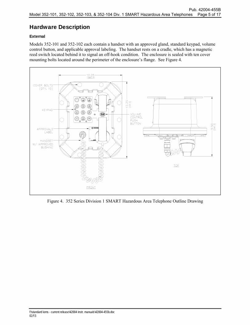
Hardware Description External
Models 352-101 and 352-102 each contain a handset with an approved gland, standard keypad, volume control button, and applicable approval labeling. The handset rests on a cradle, which has a magnetic reed switch located behind it to signal an off-hook condition. The enclosure is sealed with ten cover mounting bolts located around the perimeter of the enclosure’s flange. See Figure 4.
Figure 4. 352 Series Division 1 SMART Hazardous Area Telephone Outline Drawing
Pub. 42004-455B Model 352-101, 352-102, 352-103, & 352-104 Div. 1 SMART Hazardous Area Telephones Page 6 of 17
f:\standard ioms - current release\42004 instr. manuals\42004-455b.doc 02/13
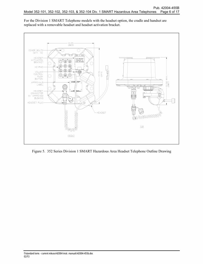
For the Division 1 SMART Telephone models with the headset option, the cradle and handset are replaced with a removable headset and headset activation bracket.
Figure 5. 352 Series Division 1 SMART Hazardous Area Headset Telephone Outline Drawing
Pub. 42004-455B Model 352-101, 352-102, 352-103, & 352-104 Div. 1 SMART Hazardous Area Telephones Page 7 of 17
f:\standard ioms - current release\42004 instr. manuals\42004-455b.doc 02/13
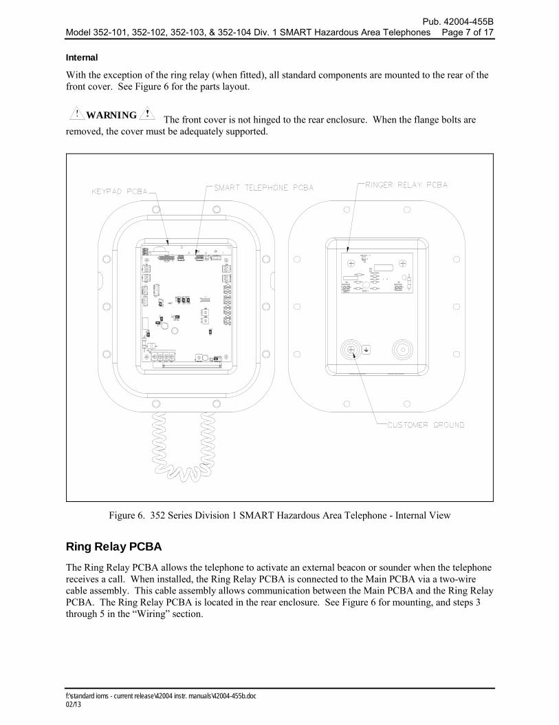
Internal
With the exception of the ring relay (when fitted), all standard components are mounted to the rear of the front cover. See Figure 6 for the parts layout.
WARNING The front cover is not hinged to the rear enclosure. When the flange bolts are removed, the cover must be adequately supported.
Figure 6. 352 Series Division 1 SMART Hazardous Area Telephone - Internal View
Ring Relay PCBA The Ring Relay PCBA allows the telephone to activate an external beacon or sounder when the telephone receives a call. When installed, the Ring Relay PCBA is connected to the Main PCBA via a two-wire cable assembly. This cable assembly allows communication between the Main PCBA and the Ring Relay PCBA. The Ring Relay PCBA is located in the rear enclosure. See Figure 6 for mounting, and steps 3 through 5 in the “Wiring” section.
Pub. 42004-455B Model 352-101, 352-102, 352-103, & 352-104 Div. 1 SMART Hazardous Area Telephones Page 8 of 17
f:\standard ioms - current release\42004 instr. manuals\42004-455b.doc 02/13
Wiring
WARNING The front cover is not hinged to the rear enclosure. When the cover bolts are removed, the cover must be adequately supported.
1. While supporting the front cover, remove the ten cover bolts from the enclosure flange. Pull the front cover far enough away to expose the internal connections and disconnect any wiring between the front cover and rear enclosure. Place the front cover aside.
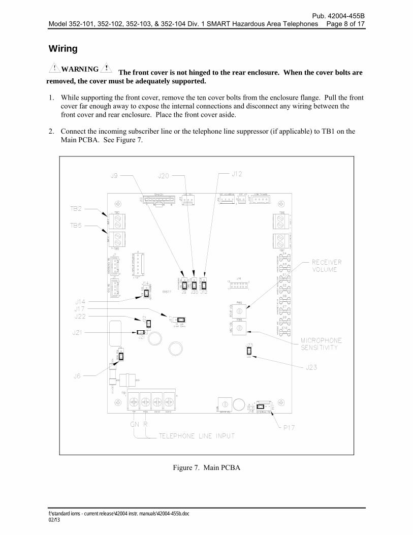
2. Connect the incoming subscriber line or the telephone line suppressor (if applicable) to TB1 on the Main PCBA. See Figure 7.
Figure 7. Main PCBA

Pub. 42004-455B Model 352-101, 352-102, 352-103, & 352-104 Div. 1 SMART Hazardous Area Telephones Page 9 of 17
f:\standard ioms - current release\42004 instr. manuals\42004-455b.doc 02/13
3. When a Ring Relay PCBA option is present, connect incoming 120 V ac power to the TB1 terminal block. See Figure 8.
Figure 8. Ring Relay PCBA
Figure 9.
4. Connect the external sounder or beacon to TB2, for activation with an incoming telephone call.
5. Reconnect the communication cable between the Main PCBA and Ring Relay PCBA, if disconnected, before reattaching the front cover.
WARNING Any external equipment connected to the Ring Relay PCBA must be rated for the hazardous area where it will be located. Improper installation or equipment may cause a safety hazard and consequent injury or property damage.

Pub. 42004-455B Model 352-101, 352-102, 352-103, & 352-104 Div. 1 SMART Hazardous Area Telephones Page 10 of 17
f:\standard ioms - current release\42004 instr. manuals\42004-455b.doc 02/13
PCBA Hardware Configuration The PCBA hardware configuration options are explained in detail in the following sections and the necessary jumper settings are identified to enable or disable each option. We recommend reading the following sections, recording the desired parameters, and then making the necessary changes. We also recommend that you make a record of your settings. The following options are controlled by specific hardware configurations. See Figure 7 on page 8 for the jumper locations.
Auto-answer Configuration
Factory Setting: Auto-answer feature enabled
The Auto-answer feature enables or disables the automatic answering of an incoming call, which allows TMA to monitor the health of this telephone via polling. When the Auto-answer feature is enabled, the telephone automatically answers the call and attempts to communicate with TMA.
Enable: Place the J14 jumper in position EN.
Disable: Place the J14 jumper in position DIS. (Do not use this setting except under the direction of GAI-Tronics personnel.)
NOTE: The Auto-answer feature must be enabled during remote programming, and to allow the GAI-Tronics Telephone Management Application PC to contact the telephone.
Polarity Configuration
Factory Setting: Non-polarity sensitive
This telephone can be configured to be polarity or non-polarity sensitive. With the non-polarized setting, the telephone operates with the telephone line’s positive terminal connected to either the tip or the ring. With the polarized setting, the telephone only operates with the telephone line’s positive terminal connected to the tip.
Non-polarity Sensitive: Place the J6 jumper in position NON.
Polarity Sensitive: Place the J6 jumper in position POL.
DTMF Gain Select Configuration
Factory Setting: Low Gain selected
Two gain selections are available in the DTMF detection circuit. In most installations, the low gain setting is recommended. The high gain setting may be necessary if the telephone is not responding to manual or TMA-generated DTMF commands.
Low Gain Selected: Place the J17 jumper in position LO.
High Gain Selected: Place the J17 jumper in position HI.
Low-Power Mode Configuration
Factory Setting: Low-Power Mode Disabled
For some installations in which only minimal loop current is available, the performance of the telephone may be improved by enabling this feature. Symptoms of minimal loop current may include low speaker volume and/or momentary muting of audio. In the majority of applications, however, the low-power mode should be disabled. The low-power mode is enabled by installing the following three jumpers: J21, J22, and J23.
Low-Power Mode Enabled: Jumpers installed at J21, J22, and J23.
Low-Power Mode Disabled: Jumpers NOT installed at J21, J22, and J23.
Pub. 42004-455B Model 352-101, 352-102, 352-103, & 352-104 Div. 1 SMART Hazardous Area Telephones Page 11 of 17
f:\standard ioms - current release\42004 instr. manuals\42004-455b.doc 02/13
Auxiliary Outputs Each telephone includes two isolated solid state switches capable of switching a maximum of 48 V dc, 125 mA or 28 VRMS ac, 80 mARMS. TB2 (OUT1) and TB5 (OUT4) on the Main PCBA provide the connections for the auxiliary outputs. Refer to Figure 7 for the location of TB2 and TB5.
Output 1 connects to TB2 on the Main PCBA. Refer to Figure 7. This output activates at the start of an incoming call and will extinguish when the handset is lifted from its cradle (call answered). This output will activate with a cadence of 2 seconds ON followed by 4 seconds OFF during this time interval.
NOTE: This output is not available on models containing the Ring Relay option.
Output 4 connects to TB5 on the Main PCBA (adjacent to TB2). This output can be remotely controlled via an appropriate DTMF command. This remote control output could be used to activate or control a door latch, gate relay solenoid, alarm, etc. from the called party location.
Extreme Cold Temperature Operation GAI-Tronics’ 352 Series Division 1 SMART Telephones are equipped for operation in extremely cold temperatures ranging to −40º C. Operation at these temperatures requires 5 V dc to be supplied to the telephone.
To connect the power, remove the jumper from header P17 pins 3 and 4 and plug it into the adjacent J18 header. Refer to Figure 7 for connector locations.
Attach the Front Cover After all adjustments have been completed, inspect and clean the machined flange joint surfaces of both the cover and box. Surfaces must be smooth, free of nicks, scratches, dirt or any foreign particle build-up that would prevent a proper seal. Surfaces must seat fully against each other to provide a proper explosion-proof joint. Clean surfaces by wiping with a clean lint-free cloth.
Apply a light coat of Killark “LUBG” lubricant to flange surfaces and close the cover. Install and tighten all cover bolts to 30 ft-lbs. Make certain no cover bolts are omitted. Use only those bolts supplied with the enclosure.
NOTE: Refer to the Killark Installation, Operation, and Maintenance Data Sheet enclosed with the unit for additional information.

Pub. 42004-455B Model 352-101, 352-102, 352-103, & 352-104 Div. 1 SMART Hazardous Area Telephones Page 12 of 17
f:\standard ioms - current release\42004 instr. manuals\42004-455b.doc 02/13
Programming All SMART Telephone models are programmable. The telephone settings are initially programmed during manufacturing and testing. After the SMART Telephone is installed, you have the option of changing the default settings. This manual provides instructions for programming basic features needed to initially set up the telephone from another touch-tone telephone.
More advanced programming requires a PC and the TMA software. For programming using the TMA terminal, refer to the manual provided with the software (Part No. 12509-037), or contact the GAI-Tronics Field Service Department.
NOTE Use a handset telephone exclusively when programming the SMART Telephone remotely. If a speakerphone is used for programming background noise could lead to the incorrect settings. (Cellular telephone is not recommended.)
Enter the Programming Mode
Read the entire “Programming” section and carefully plan your programming before beginning the process. Write down the key sequence from the Command column of Table 1, Basic Programming Commands, for the features that you need. Having your programming information written down allows you to enter the key sequence at a steady pace.
Complete the following steps to enter the programming sequence from a remote DTMF telephone:
1. Call the SMART Telephone to be programmed. (Do not use a cellular telephone.)
2. Listen for a confirmation tone during ringing, which signals that the telephone has answered.
3. Press *** to enter the programming mode.
4. Wait two seconds.
5. Enter **0000 (0000 is the factory default maintenance PIN #.)
NOTE: After sending the maintenance PIN # to the telephone, entering *20 will allow for confirmation of maintenance access to the telephone. If access is granted, the telephone responds with six DTMF digits. If access is denied, the telephone responds with two DTMF digits. If access is denied, repeat step 5 to again request access.
6. Complete the desired programming. Refer to the “Basic Programming” section for options.
7. Listen for a confirmation tone at the end of each programming sequence, which indicates the programming change was accepted.
NOTE Delays during programming greater than 5 seconds cause a programming time-out. If this occurs,
you will hear a beep before the programming sequence is completed and you must reenter the sequence.
8. When finished programming, press *99 to exit the programming mode.

Pub. 42004-455B Model 352-101, 352-102, 352-103, & 352-104 Div. 1 SMART Hazardous Area Telephones Page 13 of 17
f:\standard ioms - current release\42004 instr. manuals\42004-455b.doc 02/13
Basic Programming
The following programming command can be entered from any touch-tone telephone. Acceptance of a data transfer command is indicated via a return code transmitted as an audible DTMF tone.
Call Time-out
The call time-out feature, which is used to limit the duration of calls, can be set between one minute and 4.5 hours. The time limit is set by entering a number from 120 to 32400.
This number represents the number of half-second increments of duration. Entering 0 results in a call time-out of 4.5 hours.
Enter *37<120~32400># to assign a time limit, or change an existing time limit.
*37 Data transfer command
<120~32400> Call duration (60–16,200 seconds, 0 = 4.5 hours) – See example below.
# End of sequence indicator
Multiply the desired time limit, in minutes, by 120 to determine the call duration. Example: For a call duration of 5 minutes:
5 minutes 120 = 600
Therefore, enter the character string *37600#, and the telephone returns a DTMF check-digit.
Table 1. Basic Programming Commands
Command
Return
Description
Default Setting
*37<120~32400># c Write Call Time-out (120–32400 ½ sec, 0 disables) 10 min.
‘c’ in the above return fields is the success tone (DTMF check digit).

Pub. 42004-455B Model 352-101, 352-102, 352-103, & 352-104 Div. 1 SMART Hazardous Area Telephones Page 14 of 17
f:\standard ioms - current release\42004 instr. manuals\42004-455b.doc 02/13
Operation Models 352-101 and 352-102 Handset Operation 1. Lift the handset to place a call.
2. The handset receiver volume control, which is located on the front cover keypad, can be adjusted to the desired level by pressing the volume control push button.
NOTE: Pressing the volume control push button increases the volume in 5-dB increments. The volume starts at 0 dB and increases to a maximum volume of 20 dB. Pressing the volume control push button a fifth time will return the volume to 0 dB.
3. Dial the desired number.
4. After completion of the call, place the handset on-hook.
Figure 10.

Pub. 42004-455B Model 352-101, 352-102, 352-103, & 352-104 Div. 1 SMART Hazardous Area Telephones Page 15 of 17
f:\standard ioms - current release\42004 instr. manuals\42004-455b.doc 02/13
Models 352-103 and 352-104 Headset Operation 1. To connect the headset, plug it into the flexible plug on the front of the telephone by removing the
sealing cap from the receptacle, aligning the connector pins, and screwing the two ends together.
Figure 11.
2. To place a call, remove the headset from the headset activation bracket and flip the headset bracket forward to its preset position. See Figure 11.
3. The handset receiver volume control, which is located on the front cover keypad, can be adjusted to the desired level by pressing the volume control push button.
NOTE: Pressing the volume control push button increases the volume in 5-dB increments. The volume starts at 0 dB and increases to a maximum volume of 20 dB. Pressing the volume control push button a fifth time will return the volume to 0 dB.
4. Dial the desired number.

Pub. 42004-455B Model 352-101, 352-102, 352-103, & 352-104 Div. 1 SMART Hazardous Area Telephones Page 16 of 17
f:\standard ioms - current release\42004 instr. manuals\42004-455b.doc 02/13
5. Flip the headset activation bracket to its vertical preset position to hang up. If applicable, place the headset on the bracket after the completion of the call. Otherwise, disconnect the flexible receptacle and plug by unscrewing the two ends, and pulling them apart. When disconnected, reattach the sealing cap to the end of the receptacle. See Figure 12.
Figure 12.
Maintenance Service If your telephone requires depot service, contact your Regional Service Center for a return authorization number (RA#). Equipment should be shipped prepaid to GAI-Tronics with a return authorization number and a purchase order number. If the equipment is under warranty, repairs will be made without charge. Please include a written explanation of all defects to assist our technicians in their troubleshooting efforts.
Call 800-492-1212 inside the USA or 610-777-1374 outside the USA for help identifying the Regional Service Center closest to you.

Pub. 42004-455B Model 352-101, 352-102, 352-103, & 352-104 Div. 1 SMART Hazardous Area Telephones Page 17 of 17
f:\standard ioms - current release\42004 instr. manuals\42004-455b.doc 02/13
Specifications TMA Compatibility profile type .......................................................................................... Type A Handset
Electrical Minimum loop current (48 V dc only) ................................................................................................ 20 mA
Volume control ...................................................................... Five steps (0 dB, 5 dB, 10 dB, 15 dB, 20 dB)
Inter-digit pause .................................................................................................................................. 100 ms
Signaling tone (DTMF) ................................................................................................ 100 ms tone duration
Supervisory dc voltage ..................................................................................................... 24 V dc or 48 V dc
Network interface .......................................................................................................................... Loop Start
Auxiliary output (isolated solid state switch) .................................................................. 48 V dc @ 125 mA 28 VRMS ac @ 80 mARMS
Ring Relay PCBA output mechanical relay contact ............................................................ 250 V ac @ 5 A 30 V dc @ 5 A
Network signaling ............................................................................................................................... DTMF
Ringer Equivalence Number (REN) ....................................................................................................... 0.5B
Environmental
Operating temperature .......................................................................... −4º F to +140º F (−20º C to +60º C)
Humidity ...................................................................................................................... 90% non-condensing
Mechanical
Enclosure .............................................................................. Cast aluminum with aluminized lacquer paint
Handset Cord ....................................................... “G” style handset/PVC 6-foot extended length (standard)
Connections................................................................................ Internal screw-type barrier terminal blocks
Dimensions, Outside ............................... 10.25 W 12.25 H 9.50 D inches (260.3 311.1 241.3 mm)
Mounting .................................................. Wall or column, four 3/8-inch (10 mm) mounting feet with slots
Shipping weight ................................................................................................................ 30.0 lbs. (13.6 kg)
Net weight ......................................................................................................................... 28.0 lbs. (12.7 kg)
Approvals NRTL listed ...................................................... Hazardous locations Class I, Division 1, Groups B, C, & D
(USA and Canada) Class II, Division 1, Groups F & G Class III, Division 1
Type 4X T6 - Gas
T4A - Dust
User Instructions (USA) This equipment has been tested and found to comply with the limits for a Class A digital device, pursuant to part 15 of the FCC Rules. These limits are designed to provide reasonable protection against harmful interference when the equipment is operated in a commercial environment. This equipment generates, uses, and can radiate radio frequency energy and, if not installed and used in accordance with the instruction manual, may cause harmful interference to radio communications. Operation of this equipment in a residential area is likely to cause harmful interference in which case the user will be required to correct the interference at his own expense.

(Rev. 10/06)
WarrantyEquipment. GAI-Tronics warrants for a period of one (1) year from the date of shipment, that anyGAI-Tronics equipment supplied hereunder shall be free of defects in material and workmanship, shallcomply with the then-current product specifications and product literature, and if applicable, shall be fitfor the purpose specified in the agreed-upon quotation or proposal document. If (a) Seller’s goods proveto be defective in workmanship and/or material under normal and proper usage, or unfit for the purposespecified and agreed upon, and (b) Buyer’s claim is made within the warranty period set forth above,Buyer may return such goods to GAI-Tronics’ nearest depot repair facility, freight prepaid, at which timethey will be repaired or replaced, at Seller’s option, without charge to Buyer. Repair or replacement shallbe Buyer’s sole and exclusive remedy. The warranty period on any repaired or replacement equipmentshall be the greater of the ninety (90) day repair warranty or one (1) year from the date the originalequipment was shipped. In no event shall GAI-Tronics warranty obligations with respect to equipmentexceed 100% of the total cost of the equipment supplied hereunder. Buyer may also be entitled to themanufacturer’s warranty on any third-party goods supplied by GAI-Tronics hereunder. The applicabilityof any such third-party warranty will be determined by GAI-Tronics.
Services. Any services GAI-Tronics provides hereunder, whether directly or through subcontractors,shall be performed in accordance with the standard of care with which such services are normallyprovided in the industry. If the services fail to meet the applicable industry standard, GAI-Tronics willre-perform such services at no cost to buyer to correct said deficiency to Company's satisfaction providedany and all issues are identified prior to the demobilization of the Contractor’s personnel from the worksite. Re-performance of services shall be Buyer’s sole and exclusive remedy, and in no event shall GAI-Tronics warranty obligations with respect to services exceed 100% of the total cost of the servicesprovided hereunder.
Warranty Periods. Every claim by Buyer alleging a defect in the goods and/or services providedhereunder shall be deemed waived unless such claim is made in writing within the applicable warrantyperiods as set forth above. Provided, however, that if the defect complained of is latent and notdiscoverable within the above warranty periods, every claim arising on account of such latent defect shallbe deemed waived unless it is made in writing within a reasonable time after such latent defect is orshould have been discovered by Buyer.
Limitations / Exclusions. The warranties herein shall not apply to, and GAI-Tronics shall not beresponsible for, any damage to the goods or failure of the services supplied hereunder, to the extentcaused by Buyer’s neglect, failure to follow operational and maintenance procedures provided with theequipment, or the use of technicians not specifically authorized by GAI-Tronics to maintain or service theequipment. THE WARRANTIES AND REMEDIES CONTAINED HEREIN ARE IN LIEU OF ANDEXCLUDE ALL OTHER WARRANTIES AND REMEDIES, WHETHER EXPRESS OR IMPLIED BYOPERATION OF LAW OR OTHERWISE, INCLUDING ANY WARRANTIES OFMERCHANTABILITY OR FITNESS FOR A PARTICULAR PURPOSE.
Return PolicyIf the equipment requires service, contact your Regional Service Center for a return authorization number(RA#). Equipment should be shipped prepaid to GAI-Tronics with a return authorization number and apurchase order number. If the equipment is under warranty, repairs or a replacement will be made inaccordance with the warranty policy set forth above. Please include a written explanation of all defects toassist our technicians in their troubleshooting efforts.
Call 800-492-1212 (inside the USA) or 610-777-1374 (outside the USA) for help identifying theRegional Service Center closest to you.