model 4123 series portable pc user manual (d004-000017) · 4123 series user manual unit...
TRANSCRIPT

Make it
Daisy Data Displays, Inc.2850 Lewisberry RoadYork Haven, PA 17370717.932.9999www.daisydata.com
Includes Models:4123: Carbon Fiber, Intel Core i7, 128GB Slim Sata, 16GB RAM, Battery B/U
4123AC: Cast Aluminum, Intel Core i7, 256GB 2.5” SSD, 16GB RAM, WiFi4123AD: Cast Aluminum, Intel Atom, 128GB Slim Sata, 8GB RAM, Wi-Fi4123AE: Cast Aluminum, Intel Core i7, 256GB 2.5” SSD, 16GB RAM4123AF: Machined Aluminum, Intel Core i7, 128GB Slim Sata, 16GB RAM, Wi-Fi
Model 4123 Series Portable PC User ManualDECEMBER 2018

4123 Series User Manual
ii D004-000017
DISCLAIMER Daisy Data Displays, Inc. makes no representations or warranties with respect to the contents or use of this manual, and specifically disclaims any express or implied warranties of merchantability or fitness for any particular purpose. Daisy Data Displays, Inc. reserves the right to revise this publication and to make changes to its content, at any time, without obligation to notify any person or entity of such revisions or changes.Furthermore, Daisy Data Displays, Inc. makes no representations or warranties with respect to any Daisy Data Displays manufactured equipment, and specifically disclaims any express or implied warranties of merchantability or fitness for any particular purpose. Daisy Data Displays, Inc. reserves the right to make changes to any and all Daisy Data Displays manufactured equipment, at any time, without obligation to notify any person or entity of such changes.
FCC WARNING Computing devices and peripherals manufactured by Daisy Data Displays generate, use, and can radiate radio frequency energy, and if not installed and used in accordance with the instructions in this manual may cause interference to radio communications. Such equipment has been tested and found to comply with the limits for a Class A computing device pursuant to Subpart J of Part 15 of the FCC Rules, which are designed to provide reasonable protection against radio interference when operated in a commercial environment. Operation of this equipment in a residential area is likely to cause interference, in which case the user - at his own expense - will be required to take whatever measures may be required to correct the interference. Some components may not have been manufactured by Daisy Data Displays, Inc. If not, Daisy has been advised by the manufacturer of the component that the component has been tested and complies with the Class A computing device limits as described above.
Daisy Data Displays, Inc.2850 Lewisberry RoadYork Haven, PA 17370717.932.9999www.daisydata.com
Copyright ©2018, Daisy Data Displays, Inc. All rights reserved.
Manual: D004-000017December 2018Initial Release

4123 Series User Manual
D004-000017 iii
LIMITED WARRANTY AND LIABILITY STATEMENTTo the original purchaser, Daisy Data Displays, Inc., hereinafter referred to collectively as SELLER, warrants each of its manufactured products, and all components therein contained to be free from defects in materials and/or workmanship for a period of 12 months from the date of purchase.
Should a malfunction or other indication of defect attributable directly to faulty materials and/or workmanship occur, Seller will, at its option, and without charge to the customer for labor and parts, repair or replace the defective product, F.O.B. Seller’s plant, but Seller will not be responsible for freight from Purchaser to Seller’s plant. In no event shall Seller be liable for any loss, inconvenience or damage, whether direct, incidental, consequential or otherwise resulting from abuse, misapplication or modification of the product, improper or faulty power, damage resulting from repairs or alterations performed by unauthorized persons, or conditions resulting from any other equipment attached to the product.
Seller assumes no liability for damage occurring in transit due to the product not being returned in its original shipping material.
This warranty is exclusive and is in lieu of any warranty of merchantability or fitness for a particular purpose or other warranty of quality whether expressed or implied, except of title and against patent infringement. Correction of nonconformities, in the manner and for the period of time provided above, shall constitute fulfillment of all liabilities of the Seller to the Purchaser with respect to, or arising out of the goods, whether based on contract, negligence, strict tort or otherwise.
LIMITATION OF LIABILITYThe Seller shall not under any circumstances be liable for special or consequential damages, such as, but not limited to, damage or loss of other property or equipment, loss of profits or revenues, cost of capital, cost of purchased or replacement goods, or claims of customers of Purchaser for service interruptions. The remedies of the Purchaser set forth herein are exclusive, and the liability of Seller respect to any contract, or anything done in connection therewith such as the performance or breach thereof, of from the manufacture, sale, delivery, resale, installation or use of any goods covered by or furnished under this contract whether arising out of contract, negligence, strict tort or breach of warranty or otherwise, shall not, except as expressly provided herein, exceed the price of the goods upon which such liability is based.
This warranty gives you specific legal rights, and you may also have other rights, which vary from state to state. Seller makes every effort to provide clear and accurate technical information on the application of its products in the Operator’s Manual, and assumes no liability for misuse of the information.

4123 Series User Manual
iv D004-000017
TABLE OF CONTENTS1.0 Introduction ................................................................................................................. 1
1.1 Product Description ..............................................................................................................1
2.0 Customer Service ........................................................................................................ 23.0 Software/Hardware ...................................................................................................... 24.0 UnitCertifications ....................................................................................................... 3
4.1 Model 4123 Special Conditon ..............................................................................................3
5.0 CertificateofCompliance ........................................................................................... 46.0 Specifications .............................................................................................................. 57.0 Models/Components ................................................................................................... 57.1 BaseModel4123SeriesConfigurations ................................................................... 5
7.2 Model 4123(xx) Critical Components ...................................................................................67.3 Glandplate Components ......................................................................................................87.4 Model 4123(xx) Series Field Wiring Diagrams .....................................................................9
7.4.1 Model 4123 Field Wiring Diagram .......................................................................................... 97.4.2 Model 4123AC Field Wiring Diagram .................................................................................... 107.4.3 Model 4123AD Field Wiring Diagram .....................................................................................117.4.4 Model 4123AE Field Wiring Diagram .................................................................................... 127.4.5 Model 4123AF Field Wiring Diagram .................................................................................... 13
7.5 Model 4123(xx) Series Block Diagrams .............................................................................147.5.1 Model 4123 Block Diagram ................................................................................................... 157.5.2 Model 4123AC Block Diagram .............................................................................................. 167.5.3 Model 4123AD Block Diagram .............................................................................................. 177.5.4 Model 4123AE Block Diagram .............................................................................................. 187.5.5 Model 4123AF Block Diagram .............................................................................................. 19
7.6 Model 4123(xx) Series Mechanical Drawings ....................................................................207.6.1 Model 4123 Mechanical Drawings ........................................................................................ 207.6.2 Model 4123AC Mechanical Drawings ................................................................................... 227.6.3 Model 4123AD Mechanical Drawings ................................................................................... 247.6.4 Model 4123AE Mechanical Drawings ................................................................................... 267.6.5 Model 4123AF Mechanical Drawings ................................................................................... 28
8.0 SupplyPowerConnection(100-240VAC) ................................................................ 308.1 Bayonet-style Quick Connect/disconnect Power Connection ............................................30
8.1.1 Connecting KPT/KPSE Bayonet-style Quick Connect .......................................................... 318.2 Sealcon Cord Grip/Internal Power Connection ..................................................................31
8.2.1 Installing Internally Connected Power Source Cable ............................................................ 32
9.0 KeypadLayout ........................................................................................................... 3510.0InstallationandWarnings ......................................................................................... 3611.0BatteryStorageandOperation(Model4123) ......................................................... 3612.0Repair,MaintenanceandWarnings ......................................................................... 36
12.1 Repairs ............................................................................................................................3612.2 Maintenance ....................................................................................................................37
13.04123(xx)GeneralTroubleShooting ......................................................................... 3814.0 Revisions ................................................................................................................... 39

4123 Series User Manual Introduction
D004-000017 1
1.0 IntroductionThis manual will detail the the Model 4123 Series Portable PC manufactured by Daisy Data Display, Inc.
1.1 ProductDescriptionThe Model 4123 Series Portable PC is a mobile HMI PC certified for a Zone 2 (Information Technology) enviornment. The highly durable, sleek mobile design of the Model 4123 allows for the unit to be used in a variety of locations.
While adhering to the stringent design parameters to meet the Zone 2 hazardous location rating, Daisy Data Displays has engineered the core functionality of the Model 4123 around five (5) base model configurations, with options. This flexibility makes the Model 4123 suitable for a variety of applications that include: Oil and Gas Industry, the military, pharmeceutical and food processing.
For more information contact
2850 Lewisberry RdYork Haven, PA 17370www.daisydata.com
Daisy Data Displays, Inc.p 717.932.9999f 717.932.8000e [email protected]
:

2 D004-000017
Customer Service 4123 Series User Manual
2.0 Customer ServiceAll Daisy systems pass detailed quality control configuration and inspection before being shipped. Daisy strives to create the highest quality systems, and chooses top quality parts. However, like most electronic devices, units may experience issues over time. Should you experience problems, or have any further inquiries or comments, please contact Daisy’s customer service department:
Business Phone: (717) 932-9999 x222 Fax: (717) 932-8000 Email: [email protected]
Equipment returned to Daisy for service must be accompanied by a valid return merchandise authorization (RMA) number. Items or products shipped to Daisy without a valid RMA number will be refused. An RMA will be generated upon receipt of Company Name, Address, Contact, Product Model and Serial Numbers.
Figure 1 — Daisy Data Product ID Tag
Daisy Data Displays Inc. prides itself on offering best in class support for your products. Our technical support team can help you with installation, configuration, troubleshooting, and other support issues for all Daisy’s products.
3.0 Software/HardwareDaisy data should be contacted for any hardware or software questions/issues. Additional SSD’s or operating systems can be supplied as needed. Be aware that any modifications or alterations without the assistance of Daisy Data could affect unit certifications and implied warranty.
!! IMPORTANT NOTE ON ORDERING REPLACEMENT PARTS !!All Daisy Data Display products undergo continual improvement to ensure they meet the myriad of regulatory standards and codes for equipment operating in hazardous enviornments. These improvements or modifications may effect Daisy Data products already in the field.
With that in mind, as a customer servicing your own product, it is highly reccomended that you contact your Daisy Data Display customer service representative to confirm any part or part number you may be looking to replace. Your Daisy representative will ensure you are getting the correct part, or the possible availability of a suitable replacement part to ensure your equipment continues to meet the standards and/or codes originally intended.

4123 Series User Manual Unit Certifications
D004-000017 3
4.0 Unit CertificationsThe 4123 Series Portable PCs are third-party certified for ATEX Zone 2 locations as detailed below.
Table 1 — Product Rating DescriptionSymbol/Rating Description
European Conformity Manufactured according to applicable EU Directivies
Special Marking signifying equipment used in explosive atmospheres
II Equipment Group (Gas/Dust)3 Equipment Catagory (Normal Protection)G Hazardous Atmospheres (Gas, Vapour, Mist)Ex European Hazardous Location Standard CertifiednA Non-incendiveIIC Gas GroupT4 Temperature Class (T4=135ºC max)Gc Zone 2 Protection Methods
0ºC <Ta <+40ºC Model 4123 (Only)Operating Temperature Range
-20ºC <Ta <+55ºC Models 4123AC, 4123AD, 4123AE, 4123AF
4.1 Model 4123 Special ConditonDue to the front enclosure on the Model 4123 Portable PC having a carbon fiber faceplate, a Daisy Data Option 821 (Sun Visor) needs to be installed if exposure to ultraviolet light is anticipated. This Sun Visor (Option 821) Special Condition is specifically for the Model 4123 to meet the Resistance to Light, EN-IEC 60079-0 (clause 7.3) requirement.
When a Model 4123 utilizes the Option 821 Sun Visor in it’s construction to meet the Special Condition requirement, its product nameplate will denote this with an “X” marking proceeding the rating nomenclature as shown below:
e.g. Ex nA T4 0ºC < Ta < 40ºC X
Figure 2 — Typical Model 4123 / Product Certification ID

4 D004-000017
Certificate of Compliance 4123 Series User Manual5.0 CertificateofCompliance
EC Declaration of Conformity
Date: Wednesday, November 21, 2018 Company Name: Daisy Data Displays, Inc. Company Address: 2850 Lewisberry Road, York Haven, PA 17370
The Daisy Data Displays Series 4123(xx) Portable PC fully complies with the following directives:
• EMC Directive 2014/30/EU• Low Voltage Directive 2014/35/EU• RoHS Directive 2011/65/EU• ATEX Directive 2014/34/EU
The following EN/IEC standards were used to verify compliance:
• EN 55032:2012 (EN 61000-3-2, EN 61000-3-3)• EN 55024:2010 (EN 61000-4-2, EN 61000-4-3, EN 61000-4-4, EN 61000-4-5, EN 61000-4-6, EN 61000-4-11)• EN 60950-1:2006+A11(2009)+A12(2011)+A1(2010)+A2(2013)• EN-IEC 60079-0:2017, EN-IEC 60079-1:2014, EN-IEC 60079-7:2017, EN-IEC 60079-15:2017• IEC 60529 ed. 2.2 Dated 2013-08
According to information provided, our suppliers do not use in the manufacture of the components they supply us, hazardous substances as mentioned in the above RoHS Directive 2011/65/EU. We do not systematically analyze the supplied materials but require from our suppliers a certificate of compliance for raw materials. This declaration of conformity is used under the sole responsibility of the manufacturer.
David “Avi” Shefet President Daisy Data Displays, Inc.
Model: 4123 Rating: Ex nA IIC T4 Gc 0°C<Ta<+40°C X Models: 4123AC, 4123AD, 4123AE, 4123AF Rating: Ex nA IIC T4 Gc -20°C<Ta<+55°C
Figure3—CertificateofCompliance

4123 Series User Manual Specifications
D004-000017 5
6.0 SpecificationsTable2—Model4123xxTechnicalSpecificationsMATERIALS
All materials comply with IEC 60529 IP66 StandardsEnclosure and HardwareModel 4123 Carbon Fiber1, 6061-T6 AluminumModel4123AC,4123AD,4123AE A356.2 Cast AluminumModel 4123AF Machined Aluminum 6061-T6MECHANICAL
See dimentional drawings - See Section 7.6 Model 4123(xx) Series Mechanical DrawingsENVIRONMENTAL
Model 41231
Ingress Protection IP66Operating Temperature (No Heater) -0ºC to 40ºC
Storage Temperature -0ºC to 40ºCRelative Humidity 5% to 95%
Model 4123ACModel 4123ADModel 4123AEModel 4123AF
Ingress Protection IP66Operating Temperature (No Heater) -20ºC to 55ºC
Storage Temperature -20ºC to 75ºCRelative Humidity 5% to 95%
ELECTRICALVoltage 100-240VAC 47-63HzCurrent 1.8A
AIR REQUIREMENTSAir Pressure N/A
DISPLAYResolution (max) 1024x768Viewing Angle 80º x 80ºTypical Brightness 600 nitsColor Depth 24 bit
7.0 Models/ComponentsThe Model 4123 Series Portable PC is based upon five (5) unique base models incorporating a standard set of components/options for each model. In addition to the standard components/options, each model has a specific glandplate designed for it.
7.1 BaseModel4123SeriesConfigurationsThe Model 4123 Series Portable PCs are designed around five (5) distinct models with a standard set of critical components. Each of these models are defined by specific base model configurations as shown in Table 3 below.
Table3—4123(xx)–ULListed,ATEXZone2CertifiedModelConfigurationsModel Number Enclosure Material Processor Hard Drive RAM Misc. GlandplateAssembly
4123 Carbon Fiber1 Intel Core i7-2610UE 128GB Slim SATA 16GB Battery B/U I640-002303
4123AC Cast Alluminum Intel Core i7-6600U 256GB SSD 16GB WiFi I640-002325
4123AD Cast Alluminum Intel Atom-E3845 128GB SSD 8GB WiFi I640-002322-01
4123AE Cast Alluminum Intel Core i7-6600U 256GB SSD 16GB N/A I640-002323
4123AF Machined Alluminum Intel Core i7-2610UE 128GB SSD 16GB WiFi I640-0023251-Option821(SunVisor)mustbeusedtomeettheSpecialConditionrequirementtomaintainATEXZone2CertificationiftheModel4123carbonfiberfaceplateisexposuredtoultraviolentlight.

6 D004-000017
Models/Components 4123 Series User Manual7.2 Model4123(xx)CriticalComponents
Each of the five (5) Model 4123 Series Portable PCs are constructed around a set of standard critical components. These components are shown in Table 4.
Table4—4123(xx)ULListed,ATEXZone2CertifiedCriticalComponentsMODEL PART NO. DESCRIPTION
4123
P010-000101 110VAC Power SupplyP310-005000 Motherboard – COM Express carrier boardP000-000139 15” LCD DisplayP040-000080 15” Glass on Glass Resistive Touch ScreenI301-010005 Nine Button MembraneI202-700011 Membrane ControllerP040-100030 Touch Screen Controller (GoG Resistive)P050-200007 Intel i7 2nd gen moduleP062-120001 Storage (128GB Slim SATA)A314-318000 8GB DDR3 Memory (used with 2nd gen i7 module)E905-000017 14.4V Smart Battery
4123AC
P010-000101 110VAC Power SupplyP310-005000 Motherboard – COM Express carrier boardP000-000139 15” LCD DisplayP040-000098 15” Projected Capacitance Touch ScreenI301-010005 Nine Button MembraneI202-700011 Membrane ControllerP040-100048 Touch Screen Controller (PCAP)P050-210002 Intel i7 6th gen ModuleP060-000099 Storage (256GB 2.5” SSD)A314-418000 8GB DDR4 Memory (used with 6th gen i7 module)E907-000001 AntennaP050-000286 Wireless Card
4123AD
P010-000101 110VAC Power SupplyP310-005000 Motherboard – COM Express carrier boardP000-000139 15” LCD DisplayP040-000098 15” Projected Capacitance Touch ScreenI301-010005 Nine Button MembraneI202-700011 Membrane ControllerP040-100048 Touch Screen Controller (PCAP)P050-210000 Intel Atom E3845 ModuleP062-120001 Storage (128GB Slim SATA)A314-314003 8GB DDR3L Memory (used with Atom E3845 module)E907-000001 AntennaP050-000286 Wireless Card

4123 Series User Manual Models/Components
D004-000017 7
Table4—4123(xx)ULListed,ATEXZone2CertifiedCriticalComponentsMODEL PART NO. DESCRIPTION
4123AE
P010-000101 110VAC Power SupplyP310-005000 Motherboard – COM Express carrier boardP000-000139 15” LCD DisplayP040-000098 15” Projected Capacitance Touch ScreenI301-010005 Nine Button MembraneI202-700011 Membrane ControllerP040-100048 Touch Screen Controller (PCAP)P050-210002 Intel i7 6th gen ModuleP060-000099 Storage (256GB 2.5” SSD)A314-418000 8GB DDR4 Memory (used with 6th gen i7 module)
4123AF
P010-000101 110VAC Power SupplyP310-005000 Motherboard – COM Express carrier boardP000-000139 15” LCD DisplayP040-000098 15” Projected Capacitance Touch ScreenI301-010005 Nine Button MembraneI202-700011 Membrane ControllerP040-100048 Touch Screen Controller (PCAP)P050-200007 Intel i7 2nd gen moduleP062-120001 Storage (128GB Slim SATA)A314-318000 8GB DDR3 Memory (used with 2nd gen i7 module)E907-000001 AntennaP050-000286 Wireless Card
* Shaded parts represent critical components common in ALL Model 4123 Series units

8 D004-000017
Models/Components 4123 Series User Manual7.3 GlandplateComponents
Each 4123 Series Portable PC model is designed with specific user connections. These connections are pentrations through the enclosure that are specifically designed to seal the the internal components from any possible outside hazardous enviroment that could exist. Each model has a specific glandplate (1 of 4) designed for it as shown in Table 3. See Table 5 below for the connections assigned to each glandplate.
Table5—4123(xx)–ULListed,ATEXZone2CertifiedGlandplateConfigurationsGlandAssembly IncludesI640-002303 Cord grip, 2 USB Ports, 1 RJ45 PortI640-002322 Cord grip, 2 USB Ports, 1 RJ45 PortI640-002323 Power Connector, 2 USB Ports, 2 RJ45 PortsI640-002325 Power Connector, 2 Lemo Connectors, 2 USB Ports, 1 RJ45 Port
Figure4—I640-002303GlandplateConfiguration
Figure5—I640-002322GlandplateConfiguration
Figure6—I640-002323GlandplateConfiguration
Figure7—I640-002325GlandplateConfiguration

4123 Series User Manual Models/Components
D004-000017 9
7.4 Model4123(xx)SeriesFieldWiringDiagramsThe Model 4123 Series gland plate provides all the recepticles for external connections. Each recepticle is a standard component provided to meet the hazardous location-rated connection the unit was designed for.
The customer is responsible obtaining and making all external connections. In addition, care must be taken when making the external connections to the Model 4123xx. The unit MUST be de-enegized and/or the location rendered a non-hazardous area beforehand.
The following field wiring diagrams depict each gland plate and the external connection provided. These diagrams also show the customer-supplied connector required to make the connection and where they are to be located within the hazardous and non-hazardous area.
7.4.1 Model4123FieldWiringDiagram
Figure8—Model4123FieldWiringDiagram

10 D004-000017
Models/Components 4123 Series User Manual7.4.2 Model4123ACFieldWiringDiagram
Figure9—Model4123ACFieldWiringDiagram

4123 Series User Manual Models/Components
D004-000017 11
7.4.3 Model4123ADFieldWiringDiagram
Figure10—Model4123ADFieldWiringDiagram

12 D004-000017
Models/Components 4123 Series User Manual7.4.4 Model4123AEFieldWiringDiagram
Figure11—Model4123AEFieldWiringDiagram

4123 Series User Manual Models/Components
D004-000017 13
7.4.5 Model4123AFFieldWiringDiagram
Figure12—Model4123AFFieldWiringDiagram

14 D004-000017
Models/Components 4123 Series User Manual7.5 Model4123(xx)SeriesBlockDiagramsThe Model 4123 Series Portable PC comes in five standardized configuations as described in “7.1 Base Model 4123 Series Configurations” on page 5. The following block diagrams detail each of the base models and the components contained in each.
Model 4123 Block Diagram Model 4123AC Block Diagram Model 4123AD Block Diagram
Model 4123AF Block Diagram Model 4123AF Block Diagram
Figure13—Model 4123 Series Portable PCs

4123 Series User Manual Models/Components
D004-000017 15
7.5.1 Model4123BlockDiagram
Figure14—Model4123BlockDiagram

16 D004-000017
Models/Components 4123 Series User Manual7.5.2 Model4123ACBlockDiagram
Figure15—Model4123ACBlockDiagram

4123 Series User Manual Models/Components
D004-000017 17
7.5.3 Model4123ADBlockDiagram
Figure16—Model4123ADBlockDiagram

18 D004-000017
Models/Components 4123 Series User Manual7.5.4 Model4123AEBlockDiagram
Figure17—Model4123AEBlockDiagram

4123 Series User Manual Models/Components
D004-000017 19
7.5.5 Model4123AFBlockDiagram
Figure18—Model4123AFBlockDiagram

20 D004-000017
Models/Components 4123 Series User Manual7.6 Model4123(xx)SeriesMechanicalDrawings
7.6.1 Model4123MechanicalDrawings
1 1
2 2
3 3
4 4
5 5
6 6
7 7
8 8
AA
BB
CC
DD
SHEE
T 1
OF
2 D3
02-0
0040
6SI
ZE DSC
ALE
REV 01
THIS
DOC
UMEN
T IS
CON
SIDE
RED
PROP
RIET
ARY
TO D
3 DI
SPLA
YS, I
NC.
THE
USE
OR R
EPRO
DUCT
ION
OFTH
IS D
OCUM
ENT
IS P
ROHI
BITE
DEX
CEPT
AS
AUTH
ORIZ
ED B
Y TH
E CO
RPOR
ATIO
N IN
WRI
TING
.SP
ECIF
ICAT
IONS
ARE
SUB
JECT
TO C
HANG
E W
ITHO
UT N
OTIC
E.
TOLE
RAN
CES
DIM
ENSI
ON
S AR
EIN
IN
CHES
DRAW
N
CHEC
KED
FRAC
TION
S/
32"
DECI
MAL
S.X
X =
0
3
.XXX
=
015
ANGL
ES
G. D
RAPC
HO
N. W
AGNE
R
APPR
OVAL
DATE
CUST
DW
G,41
23,C
ARBO
N FI
BER
TITL
E
DWG
NO
2850
Lew
isber
ry R
oad
York
Hav
en, P
A 17
370
Phon
e: 7
17.9
32.9
999
Visit
us
atw
ww
.d3i
nc.n
et9/
12/2
018
8/29
/201
8
12.75
16.5
0
21.2
2
1.31
2.25
4.41
4.61
CARB
ON F
IBER
TWIL
L W
EAVE
FACE
PLA
TE
CARB
ON F
IBER
TWIL
L W
EAVE
REAR
PLA
TE
ENCL
OSUR
E60
61-T
6 AL
POW
ER C
ABLE
GLA
NDM
ANUF
: SEA
LCON
P/N:
CD1
3NA-
EX
ETHE
RNET
MAN
UF: A
MPH
ENOL
PCD
P/N:
RJF
TV21
NM
ATTI
NG P
/N: R
JFTV
C2N
USB
MAN
UF: A
MPH
ENOL
PCD
P/N:
USB
FTV2
2NM
ATTI
NG P
/N: U
SBFT
VC2NGL
AND
I/O
SS H
OLE
SEAL
SM
ANUF
: HOF
FMAN
P/N:
ASP
BGSS
HAND
LE60
63 A
NODI
ZED
AL
HAND
LE B
RACK
ET60
61-T
6 AL
QTY
(4)
EXTE
NDER
BOX
6061
-T6
AL
GLAN
D EX
TEND
ER P
LATE
6061
-T6
ALHT
800
MED
IUM
CEL
LULA
R SI
LICO
NE F
OAM
RUB
BER
w/ 3
M A
DHES
IVE
TAPE
468M
P-20
0 ON
ONE
SID
E
REAR
HEA
TSIN
K60
61-T
6 AL
REVI
SION
HIS
TORY
ZONE
REV
DESC
RIPT
ION
DATE
APR
N/A
1DE
TAIL
ED M
ATER
IALS
, ADD
ED S
HEET
28/
29/2
018
NGW
GLAN
D PL
ATE
6061
-T6
AL
HT 8
00 M
EDIU
M C
ELLU
LAR
SILI
CONE
FOA
M R
UBBE
Rw
/ 3M
ADH
ESIV
E TA
PE46
8MP-
200
ON O
NE S
IDE
12.1
0
15" P
ROJE
CTED
CAP
ACIT
IVE
TOUC
H SC
REEN
DAW
AR P
/N D
W02
975-
A
9.11
21.2
2
1.18
3.50
7.00
13.0
01.
75
1.832.00
9.50
DAIS
Y LO
GO L
ABEL
Figure19—Model4123MechanicalDrawing(1of2)

4123 Series User Manual Models/Components
D004-000017 21
1 1
2 2
3 3
4 4
5 5
6 6
7 7
8 8
AA
BB
CC
DD
SHEE
T 2
OF
2 D3
02-0
0040
6SI
ZE DSC
ALE
REV 01
THIS
DOC
UMEN
T IS
CON
SIDE
RED
PROP
RIET
ARY
TO D
3 DI
SPLA
YS, I
NC.
THE
USE
OR R
EPRO
DUCT
ION
OFTH
IS D
OCUM
ENT
IS P
ROHI
BITE
DEX
CEPT
AS
AUTH
ORIZ
ED B
Y TH
E CO
RPOR
ATIO
N IN
WRI
TING
.SP
ECIF
ICAT
IONS
ARE
SUB
JECT
TO C
HANG
E W
ITHO
UT N
OTIC
E.
TOLE
RAN
CES
DIM
ENSI
ON
S AR
EIN
IN
CHES
DRAW
N
CHEC
KED
FRAC
TION
S/
32"
DECI
MAL
S.X
X =
0
3
.XXX
= 0
15
ANGL
ES
G. D
RAPC
HO
N. W
AGNE
R
APPR
OVAL
DATE
CUST
DW
G,41
23,C
ARBO
N FI
BER
TITL
E
DWG
NO
2850
Lew
isber
ry R
oad
York
Hav
en, P
A 17
370
Phon
e: 7
17.9
32.9
999
Visit
us
atw
ww
.d3i
nc.n
et9/
12/2
018
8/29
/201
8
.00
.52
.73
3.703.814.535.255.426.006.586.757.027.507.998.258.529.009.499.75
10.4511.2511.7012.6912.8015.7715.99
.00
.52
.73
1.61
1.70
2.67
2.76
2.99
4.17
4.30
5.25
5.80
7.42
7.50
9.05
9.76
10.5
510
.67
12.0
212
.24
.00
2.00
10.7
5
.00
1.13
1/4-
20 x
.500
UNC
FL
AT H
EAD
SOCK
ETSS
MAC
HINE
QTY
(2)
10-3
2 x
.375
L UN
C TO
RXPA
N HE
AD S
S M
ACHI
NEQT
Y (2
2)
6-32
x .3
75L
UNC
TORX
PAN
HEAD
SS
MAC
HINE
QTY
(16)
.00
3.88
12.63
.00
1.13
.00
1.13
.00
3.88
12.63
.00
1.13
.00
2.00
10.7
5
1/4-
20 x
.375
L UN
CLO
W P
ROFI
LE C
AP S
OCKE
T HE
ADSS
MAC
HINE
QTY
(2)
1.50
1.37
2.18
2.87
3.005.45
9.39
2.002.16
5.12
6.28
8.25
11.37
14.3414.50
3.24
5.74
10.76
13.26
4-40
x .3
75L
UNC
PHIL
LIPS
PAN
HEAD
SS
MAC
HINE
QTY
(12)
10-3
2 UN
FVE
SA M
OUNT
HOL
ES
REVI
SION
HIS
TORY
ZONE
REV
DESC
RIPT
ION
DATE
APR
N/A
1DE
TAIL
ED M
ATER
IALS
, ADD
ED S
HEET
28/
29/2
018
NGW
6-32
x .3
75L
UNC
TORX
PAN
HEAD
SS
MAC
HINE
QTY
(16)
1/4-
20 x
.375
L UN
CLO
W P
ROFI
LE C
AP S
OCKE
T HE
ADSS
MAC
HINE
QTY
(2)
1/4-
20 x
.500
UNC
FL
AT H
EAD
SOCK
ETSS
MAC
HINE
QTY
(2)
Figure20—Model4123MechanicalDrawing(2of2)

22 D004-000017
Models/Components 4123 Series User Manual7.6.2 Model4123ACMechanicalDrawings
1 1
2 2
3 3
4 4
5 5
6 6
7 7
8 8
AA
BB
CC
DD
SHEE
T 1
OF
2
SIZE D
SCAL
E
REV 01
THIS
DOC
UMEN
T IS
CON
SIDE
RED
PROP
RIET
ARY
TO D
3 DI
SPLA
YS, I
NC.
THE
USE
OR R
EPRO
DUCT
ION
OFTH
IS D
OCUM
ENT
IS P
ROHI
BITE
DEX
CEPT
AS
AUTH
ORIZ
ED B
Y TH
E CO
RPOR
ATIO
N IN
WRI
TING
.SP
ECIF
ICAT
IONS
ARE
SUB
JECT
TO C
HANG
E W
ITHO
UT N
OTIC
E.
TOLE
RAN
CES
DIM
ENSI
ON
S AR
EIN
IN
CHES
DRAW
N
CHEC
KED
FRAC
TION
S/
32"
DECI
MAL
S.X
X =
0
3
.XXX
= 0
15
ANGL
ES
G. D
RAPC
HO
J. KU
YKEN
DALL
APPR
OVAL
DATE
CUST
DW
G,41
23AC
,WKS
,CAS
T,NI
TITL
E
DWG
NO
2850
Lew
isber
ry R
oad
York
Hav
en, P
A 17
370
Phon
e: 7
17.9
32.9
999
Visit
us
atw
ww
.d3i
nc.n
et9/
12/2
018
6/19
/201
8
D302
-000
421
4.65
1.19
16.7
2
12.97
CAST
A35
6.2
AL R
EAR
PANE
L
REVI
SION
HIS
TORY
ZONE
REV
DESC
RIPT
ION
DATE
APR
N/A
01AD
DED
MAT
ERIA
L AN
D HA
RDW
ARE
DETA
ILS
& DI
MS,
ADD
ED S
HEET
28/
29/2
018
JLK
12.1
0
21.3
3
9.11
DAIS
Y LO
GOLA
BEL
15" P
ROJE
CTED
CAP
ACIT
IVE
TOUC
H SC
REEN
DAW
AR P
/N D
W02
975-
A
CAST
A35
6.2
ALEN
CLOS
URE
HAND
LE B
RACK
ET Q
TY (4
)60
61-T
6 AL
HAND
LE Q
TY (2
)60
63 A
NODI
ZED
AL
HT 8
00 M
EDIU
M
CELL
ULAR
SIL
ICON
E FO
AM R
UBBE
R w
/3M
ADH
ESIV
E TA
PE
468M
P-20
0ON
ONE
SID
E
EXTE
NDER
PLA
TE60
61-T
6 AL
4.10
2.25
1.77
2.04
WIF
I ANT
ENNA
QTY
(2)
GLAN
D PL
ATE
6061
-T6
AL
POW
ERIT
T CA
NNON
P/N
KPSE
02E1
23PA
206
ETHE
RNET
L-CO
M P
/NEC
RD02
01U0
0
USB'
SUS
BFIR
EWIR
E P/
NRR
-211
300-
03-Z
6C
LEM
O'S
LEM
O US
A IN
C. P
/NER
A.2E
.305
.CLL
3.61
1.29
12.6
5
6.77 2.00
9.50
Figure21—Model4123ACMechanicalDrawing(1of2)

4123 Series User Manual Models/Components
D004-000017 23
1 1
2 2
3 3
4 4
5 5
6 6
7 7
8 8
AA
BB
CC
DD
SHEE
T 2
OF
2
SIZE D
SCAL
E
REV 01
THIS
DOC
UMEN
T IS
CON
SIDE
RED
PROP
RIET
ARY
TO D
3 DI
SPLA
YS, I
NC.
THE
USE
OR R
EPRO
DUCT
ION
OFTH
IS D
OCUM
ENT
IS P
ROHI
BITE
DEX
CEPT
AS
AUTH
ORIZ
ED B
Y TH
E CO
RPOR
ATIO
N IN
WRI
TING
.SP
ECIF
ICAT
IONS
ARE
SUB
JECT
TO C
HANG
E W
ITHO
UT N
OTIC
E.
TOLE
RAN
CES
DIM
ENSI
ON
S AR
EIN
IN
CHES
DRAW
N
CHEC
KED
FRAC
TION
S/
32"
DECI
MAL
S.X
X =
0
3
.XXX
= 0
15
ANGL
ES
G. D
RAPC
HO
J. KU
YKEN
DALL
APPR
OVAL
DATE
CUST
DW
G,41
23AC
,WKS
,CAS
T,NI
TITL
E
DWG
NO
2850
Lew
isber
ry R
oad
York
Hav
en, P
A 17
370
Phon
e: 7
17.9
32.9
999
Visit
us
atw
ww
.d3i
nc.n
et9/
12/2
018
6/19
/201
8
D302
-000
421
REVI
SION
HIS
TORY
ZONE
REV
DESC
RIPT
ION
DATE
APR
N/A
01AD
DED
MAT
ERIA
L AN
D HA
RDW
ARE
DETA
ILS
& DI
MS,
ADD
ED S
HEET
28/
29/2
018
JLK
DR
AFT
FACE
VIE
WD
RAFT
FAC
E VI
EW
DRA
FT F
ACE
VIEW
DRA
FT F
ACE
VIEW
1.14
1.68
1.68
1.14
1.68
1.68
.18
.18
1.14
.18
.18
1.14
1/4-
20 x
.500
UNC
SO
CKET
HEA
D FL
ATSS
MAC
HINE
SCR
EWQT
Y (2
)
1/4-
20 x
.500
UNC
SO
CKET
HEA
D FL
AT
SS M
ACHI
NE S
CREW
QTY
(2)
1/4-
20 x
.375
UNC
SO
CKET
HEA
DCA
P LO
W P
ROFI
LESS
SCR
EWS
QTY
(2)
1/4-
20 x
.375
UNC
SO
CKET
HEA
DCA
P LO
W P
ROFI
LESS
SCR
EWS
QTY
(2)
.00
.62
.84
1.76
1.89
2.70
2.82
3.10
5.35
5.84
7.61
9.78
9.87
12.1
312
.34
.00
.62
.84
3.813.924.645.366.116.867.61
9.119.86
10.5611.3611.8112.7912.90
15.8816.09
1.61
2.29
1.48
2.98
3.11
6.39
10.33
3.34
5.85
8.36
10.86
13.37
4-40
x .3
75 U
NC P
HILL
IPS
PAN
HEAD
SS
MAC
HINE
SCRE
WS
QTY
(8)
10-3
2 x
.375
UNF
TOR
XPA
N HE
AD S
S M
ACHI
NESC
REW
S QT
Y (2
2)
6-32
x .3
75 U
NC T
ORX
PAN
HEAD
SS
MAC
HINE
SCRE
WS
QTY
(16)
1/4-
28 U
NF V
ESA
MOU
NT H
OLES
Figure22—Model4123ACMechanicalDrawing(2of2)

24 D004-000017
Models/Components 4123 Series User Manual7.6.3 Model4123ADMechanicalDrawings
1 1
2 2
3 3
4 4
5 5
6 6
7 7
8 8
AA
BB
CC
DD
SHEE
T 1
OF
2 D3
02-0
0041
2SI
ZE DSC
ALE
REV 01
THIS
DOC
UMEN
T IS
CON
SIDE
RED
PROP
RIET
ARY
TO D
3 DI
SPLA
YS, I
NC.
THE
USE
OR R
EPRO
DUCT
ION
OFTH
IS D
OCUM
ENT
IS P
ROHI
BITE
DEX
CEPT
AS
AUTH
ORIZ
ED B
Y TH
E CO
RPOR
ATIO
N IN
WRI
TING
.SP
ECIF
ICAT
IONS
ARE
SUB
JECT
TO C
HANG
E W
ITHO
UT N
OTIC
E.
TOLE
RAN
CES
DIM
ENSI
ON
S AR
EIN
IN
CHES
DRAW
N
CHEC
KED
FRAC
TION
S/
32"
DECI
MAL
S.X
X =
0
3
.XXX
= 0
15
ANGL
ES
G. D
RAPC
HO
N. W
AGNE
R
APPR
OVAL
DATE
CUST
DW
G, 4
123A
D, 1
5" C
AST
TITL
E
DWG
NO
2850
Lew
isber
ry R
oad
York
Hav
en, P
A 17
370
Phon
e: 7
17.9
32.9
999
Visit
us
atw
ww
.d3i
nc.n
et9/
12/2
018
8/29
/201
8USB-
A IN
PUT
MAN
UF: U
SB F
IREW
IRE
P/N:
RR-
2113
00-0
3-Z6
C
POW
ER C
ORD
GRIP
MAN
UF: S
EALC
ONP/
N: C
D21N
R-EX
21.3
3
12.97
16.7
24.
39
2.25 3.
30
ETHE
RNET
RJ4
5 -N
ETW
ORK
INPU
TM
ANUF
: L-C
OMP/
N: E
CRD0
201U
00
4.10
EXTE
NDED
RAN
GEW
IFI A
NTEN
NAS
(ROT
ATE
90°) GL
AND
I/O
SS H
OLE
SEAL
SM
ANUF
: HOF
FMAN
P/N:
A-S
PBGS
SREVI
SION
HIS
TORY
ZONE
REV
DESC
RIPT
ION
DATE
APR
N/A
01DE
TAIL
ED M
ATER
IALS
, ADD
ED S
HEET
28/
29/2
018
NGW
GLAN
D PL
ATE
6061
-T6
AL
15" P
ROJE
CTED
CAP
ACIT
IVE
TOUC
H SC
REEN
DAW
AR P
/N D
W02
975-
A
12.1
0
9.11
HT 8
00 M
EDIU
M C
ELLU
LAR
SILI
CONE
FOA
M R
UBBE
Rw
/ 3M
ADH
ESIV
E TA
PE46
8MP-
200
ON O
NE S
IDE
ENCL
OSUR
EA3
56.2
AL
REAR
COV
ERA3
56.2
AL
GLAN
D BO
X EX
TEND
ER60
61-T
6 AL
HAND
LE B
RACK
ETS
6061
-T6
ALQT
Y (4
)
HAND
LEAN
ODIZ
ED 6
063
ALQT
Y (2
)
DAIS
Y LO
GO L
ABEL
1.29
2.00
3.61
9.50
1.77
2.04
6.77
12.6
5
Figure23—Model4123ADMechanicalDrawing(1of2)

4123 Series User Manual Models/Components
D004-000017 25
1 1
2 2
3 3
4 4
5 5
6 6
7 7
8 8
AA
BB
CC
DD
SHEE
T 2
OF
2 D3
02-0
0041
2SI
ZE DSC
ALE
REV 01
THIS
DOC
UMEN
T IS
CON
SIDE
RED
PROP
RIET
ARY
TO D
3 DI
SPLA
YS, I
NC.
THE
USE
OR R
EPRO
DUCT
ION
OFTH
IS D
OCUM
ENT
IS P
ROHI
BITE
DEX
CEPT
AS
AUTH
ORIZ
ED B
Y TH
E CO
RPOR
ATIO
N IN
WRI
TING
.SP
ECIF
ICAT
IONS
ARE
SUB
JECT
TO C
HANG
E W
ITHO
UT N
OTIC
E.
TOLE
RAN
CES
DIM
ENSI
ON
S AR
EIN
IN
CHES
DRAW
N
CHEC
KED
FRAC
TION
S/
32"
DECI
MAL
S.X
X =
0
3
.XXX
= 0
15
ANGL
ES
G. D
RAPC
HO
N. W
AGNE
R
APPR
OVAL
DATE
CUST
DW
G, 4
123A
D, 1
5" C
AST
TITL
E
DWG
NO
2850
Lew
isber
ry R
oad
York
Hav
en, P
A 17
370
Phon
e: 7
17.9
32.9
999
Visit
us
atw
ww
.d3i
nc.n
et9/
12/2
018
8/29
/201
8
REVI
SION
HIS
TORY
ZONE
REV
DESC
RIPT
ION
DATE
APR
N/A
01DE
TAIL
ED M
ATER
IALS
, ADD
ED S
HEET
28/
29/2
018
NGW
DRA
FT F
ACE
VIEW
DRA
FT F
ACE
VIEW
DRA
FT F
ACE
VIEW
DRA
FT F
ACE
VIEW
.00
1.68
10.43
.00
1.14
.00
.94
.00
.18
8.93
.00
.18
8.93
.00
1.14
.00
1.14
.00
1.68
10.43
.00
.62
.84
1.76
2.82
3.10
5.35
7.61
9.87
12.1
312
.34
.00
3.813.924.645.365.586.116.646.867.618.369.119.86
10.5611.3611.8112.8012.90
10-3
2 x
.375
L UN
C TO
RXPA
N HE
AD S
S M
ACHI
NEQT
Y (2
2)
4-40
x .2
50L
UNC
PHIL
LIPS
PAN
HEAD
SS
MAC
HINE
QTY
(4)
.62
.84
3.35
5.85
8.36
10.86
13.37
15.8816.09
1.48
1.61
2.29
2.98
3.11
6-32
x .3
75L
UNC
TORX
PAN
HEAD
SS
MAC
HINE
QTY
(16)
5.84
9.78
6.39
10.33
1/4-
20 x
.375
L UN
CLO
W P
ROFI
LE C
AP S
OCKE
T HE
ADSS
MAC
HINE
QTY
(2)
1/4-
20 x
.375
L UN
CLO
W P
ROFI
LE C
AP S
OCKE
T HE
ADSS
MAC
HINE
QTY
(2)
1/4-
20 x
.500
UNC
FL
AT H
EAD
SOCK
ETSS
MAC
HINE
QTY
(2)
1/4-
20 x
.500
UNC
FL
AT H
EAD
SOCK
ETSS
MAC
HINE
QTY
(2)
Figure24—Model4123ADMechanicalDrawings(2of2)

26 D004-000017
Models/Components 4123 Series User Manual
7.6.4 Model4123AEMechanicalDrawings
1 1
2 2
3 3
4 4
5 5
6 6
7 7
8 8
AA
BB
CC
DD
SHEE
T 1
OF
2 D3
02-0
0041
2SI
ZE DSC
ALE
REV 01
THIS
DOC
UMEN
T IS
CON
SIDE
RED
PROP
RIET
ARY
TO D
3 DI
SPLA
YS, I
NC.
THE
USE
OR R
EPRO
DUCT
ION
OFTH
IS D
OCUM
ENT
IS P
ROHI
BITE
DEX
CEPT
AS
AUTH
ORIZ
ED B
Y TH
E CO
RPOR
ATIO
N IN
WRI
TING
.SP
ECIF
ICAT
IONS
ARE
SUB
JECT
TO C
HANG
E W
ITHO
UT N
OTIC
E.
TOLE
RAN
CES
DIM
ENSI
ON
S AR
EIN
IN
CHES
DRAW
N
CHEC
KED
FRAC
TION
S/
32"
DECI
MAL
S.X
X =
0
3
.XXX
= 0
15
ANGL
ES
G. D
RAPC
HO
N. W
AGNE
R
APPR
OVAL
DATE
CUST
DW
G, 4
123A
D, 1
5" C
AST
TITL
E
DWG
NO
2850
Lew
isber
ry R
oad
York
Hav
en, P
A 17
370
Phon
e: 7
17.9
32.9
999
Visit
us
atw
ww
.d3i
nc.n
et9/
12/2
018
8/29
/201
8USB-
A IN
PUT
MAN
UF: U
SB F
IREW
IRE
P/N:
RR-
2113
00-0
3-Z6
C
POW
ER C
ORD
GRIP
MAN
UF: S
EALC
ONP/
N: C
D21N
R-EX
21.3
3
12.97
16.7
24.
39
2.25 3.
30
ETHE
RNET
RJ4
5 -N
ETW
ORK
INPU
TM
ANUF
: L-C
OMP/
N: E
CRD0
201U
00
4.10
EXTE
NDED
RAN
GEW
IFI A
NTEN
NAS
(ROT
ATE
90°) GL
AND
I/O
SS H
OLE
SEAL
SM
ANUF
: HOF
FMAN
P/N:
A-S
PBGS
SREVI
SION
HIS
TORY
ZONE
REV
DESC
RIPT
ION
DATE
APR
N/A
01DE
TAIL
ED M
ATER
IALS
, ADD
ED S
HEET
28/
29/2
018
NGW
GLAN
D PL
ATE
6061
-T6
AL
15" P
ROJE
CTED
CAP
ACIT
IVE
TOUC
H SC
REEN
DAW
AR P
/N D
W02
975-
A
12.1
0
9.11
HT 8
00 M
EDIU
M C
ELLU
LAR
SILI
CONE
FOA
M R
UBBE
Rw
/ 3M
ADH
ESIV
E TA
PE46
8MP-
200
ON O
NE S
IDE
ENCL
OSUR
EA3
56.2
AL
REAR
COV
ERA3
56.2
AL
GLAN
D BO
X EX
TEND
ER60
61-T
6 AL
HAND
LE B
RACK
ETS
6061
-T6
ALQT
Y (4
)
HAND
LEAN
ODIZ
ED 6
063
ALQT
Y (2
)
DAIS
Y LO
GO L
ABEL
1.29
2.00
3.61
9.50
1.77
2.04
6.77
12.6
5
Figure25—Model4123AEMechanicalDrawing(1of2)

4123 Series User Manual Models/Components
D004-000017 27
1 1
2 2
3 3
4 4
5 5
6 6
7 7
8 8
AA
BB
CC
DD
SHEE
T 2
OF
2 D3
02-0
0038
7SI
ZE DSC
ALE
REV 03
THIS
DOC
UMEN
T IS
CON
SIDE
RED
PROP
RIET
ARY
TO D
3 DI
SPLA
YS, I
NC.
THE
USE
OR R
EPRO
DUCT
ION
OFTH
IS D
OCUM
ENT
IS P
ROHI
BITE
DEX
CEPT
AS
AUTH
ORIZ
ED B
Y TH
E CO
RPOR
ATIO
N IN
WRI
TING
.SP
ECIF
ICAT
IONS
ARE
SUB
JECT
TO C
HANG
E W
ITHO
UT N
OTIC
E.
TOLE
RAN
CES
DIM
ENSI
ON
S AR
EIN
IN
CHES
DRAW
N
CHEC
KED
FRAC
TION
S/
32"
DECI
MAL
S.X
X =
0
3
.XXX
= 0
15
ANGL
ES
G. D
RAPC
HO
N. W
AGNE
R
APPR
OVAL
DATE
CUST
DW
G,41
23AE
15"
, N.O
.V.
TITL
E
DWG
NO
2850
Lew
isber
ry R
oad
York
Hav
en, P
A 17
370
Phon
e: 7
17.9
32.9
999
Visit
us
atw
ww
.d3i
nc.n
et9/
12/2
018
8/17
/201
7
DR
AFT
FACE
VIE
WD
RAF
T FA
CE V
IEW
DRA
FT F
ACE
VIEW
DRA
FT F
ACE
VIEW
.00
1.14
.00
1.68
10.43
.00
.18
8.93
.00
1.14
.00
1.14
.00
1.68
10.43
.00
1.14
.00
.18
8.93
.00
.62
.84
1.89
2.70
3.10
5.35
7.61
9.87
12.1
312
.34
1.32
1.45
2.29
3.14
3.265.84
9.78
.00
3.653.764.154.564.975.365.685.686.216.746.746.867.688.218.368.749.86
10.1611.3612.0112.9513.06
3.34
5.856.39
8.36
10.3310.86
13.37
15.8816.09
.84
.62
1/4-
20 x
.375
L UN
CLO
W P
ROFI
LE C
AP S
OCKE
T HE
ADSS
MAC
HINE
QTY
(2)
1/4-
20 x
.375
L UN
CLO
W P
ROFI
LE C
AP S
OCKE
T HE
ADSS
MAC
HINE
QTY
(2)
1/4-
20 x
.375
L UN
CLO
W P
ROFI
LE C
AP S
OCKE
T HE
ADSS
MAC
HINE
QTY
(2)
1/4-
20 x
.375
L UN
CLO
W P
ROFI
LE C
AP S
OCKE
T HE
ADSS
MAC
HINE
QTY
(2)
10-3
2 x
.375
L UN
C TO
RXPA
N HE
AD S
S M
ACHI
NEQT
Y (2
2) 6-32
x .2
5L U
NC T
ORX
PAN
HEAD
SS
MAC
HINE
QTY
(16)
4-40
x .2
50L
UNC
PHIL
LIPS
PAN
HEAD
SS
MAC
HINE
QTY
(12)
1/4-
28 U
NCVE
SA M
OUNT
HOL
ES
REVI
SION
HIS
TORY
ZONE
REV
DESC
RIPT
ION
DATE
APR
N/A
01UP
DATE
D M
ODEL
, VIE
WS,
& D
IMS
5/15
/201
5JL
KN/
A02
REM
OVED
HAN
DLES
5/21
/201
8JL
KN/
A03
DETA
ILED
MAT
ERIA
LS, A
DDED
SHE
ET 2
8/29
/201
8NG
W
Figure26—Model4123AEMechanicalDrawing(2of2)

28 D004-000017
Models/Components 4123 Series User Manual7.6.5 Model4123AFMechanicalDrawings
1 1
2 2
3 3
4 4
5 5
6 6
7 7
8 8
AA
BB
CC
DD
SHEE
T 1
OF
2
SIZE D
SCAL
E
REV 01
THIS
DOC
UMEN
T IS
CON
SIDE
RED
PROP
RIET
ARY
TO D
3 DI
SPLA
YS, I
NC.
THE
USE
OR R
EPRO
DUCT
ION
OFTH
IS D
OCUM
ENT
IS P
ROHI
BITE
DEX
CEPT
AS
AUTH
ORIZ
ED B
Y TH
E CO
RPOR
ATIO
N IN
WRI
TING
.SP
ECIF
ICAT
IONS
ARE
SUB
JECT
TO C
HANG
E W
ITHO
UT N
OTIC
E.
TOLE
RAN
CES
DIM
ENSI
ON
S AR
EIN
IN
CHES
DRAW
N
CHEC
KED
FRAC
TION
S/
32"
DECI
MAL
S.X
X =
0
3
.XXX
= 0
15
ANGL
ES
G. D
RAPC
HO
J. KU
YKEN
DALL
APPR
OVAL
DATE
CUST
DW
G,41
23AF
,WKS
,MOB
ILE,
NI
TITL
E
DWG
NO
2850
Lew
isber
ry R
oad
York
Hav
en, P
A 17
370
Phon
e: 7
17.9
32.9
999
Visit
us
atw
ww
.d3i
nc.n
et9/
12/2
018
6/19
/201
8
D302
-000
420
4.65
1.13
12.75
16.5
0
2.25
4.22
6061
-T6
AL E
NCLO
SURE
WIF
I ANT
ENNA
QT
Y (2
)
REAR
PAN
EL60
61-T
6 AL
HAND
LE B
RACK
ET Q
TY (4
)60
61-T
6 AL
HAND
LE Q
TY (2
)60
63 A
NODI
ZED
AL
EXTE
NDER
PLA
TE60
61-T
6 AL
BEZE
L60
61-T
6-AL
HEAT
SINK
PLA
TE60
61-T
6 AL
HT 8
00 M
EDIU
M
CELL
ULAR
SIL
ICON
E FO
AM R
UBBE
R w
/3M
ADH
ESIV
E TA
PE
468M
P-20
0ON
ONE
SID
E
GLAN
D PL
ATE
6061
-T6
AL
1.18
3.50
1.83
1.75
REVI
SION
HIS
TORY
ZONE
REV
DESC
RIPT
ION
DATE
APR
N/A
01AD
DED
MAT
ERIA
L AN
D HA
RDW
ARE
DETA
ILS
& DI
MS,
ADD
ED S
HEET
29/
6/20
18JL
K
POW
ERIT
T CA
NNON
P/N
KPSE
02E1
23PA
206
ETHE
RNET
L-CO
M P
/NEC
RD02
01U0
0
USB'
SUS
BFIR
EWIR
E P/
NRR
-211
300-
03-Z
6C
LEM
O'S
LEM
O US
A IN
C. P
/NER
A.2E
.305
.CLL
DAIS
Y LO
GOLA
BEL
11.9
7
8.98
15" P
ROJE
CTED
CAP
ACIT
IVE
TOUC
H SC
REEN
DAW
AR P
/N D
W02
975-
A
21.2
2
HT 8
00 M
EDIU
M
CELL
ULAR
SIL
ICON
E FO
AM R
UBBE
R w
/3M
ADH
ESIV
E TA
PE
468M
P-20
0ON
ONE
SID
E
EXTE
NDER
PLA
TE60
61-T
6 AL
13.0
0
7.00 2.00
9.50
Figure27—Model4123AFMechanicalDrawing(1of2)

4123 Series User Manual Models/Components
D004-000017 29
1 1
2 2
3 3
4 4
5 5
6 6
7 7
8 8
AA
BB
CC
DD
SHEE
T 2
OF
2
SIZE D
SCAL
E
REV 01
THIS
DOC
UMEN
T IS
CON
SIDE
RED
PROP
RIET
ARY
TO D
3 DI
SPLA
YS, I
NC.
THE
USE
OR R
EPRO
DUCT
ION
OFTH
IS D
OCUM
ENT
IS P
ROHI
BITE
DEX
CEPT
AS
AUTH
ORIZ
ED B
Y TH
E CO
RPOR
ATIO
N IN
WRI
TING
.SP
ECIF
ICAT
IONS
ARE
SUB
JECT
TO C
HANG
E W
ITHO
UT N
OTIC
E.
TOLE
RAN
CES
DIM
ENSI
ON
S AR
EIN
IN
CHES
DRAW
N
CHEC
KED
FRAC
TION
S/
32"
DECI
MAL
S.X
X =
0
3
.XXX
= 0
15
ANGL
ES
G. D
RAPC
HO
J. KU
YKEN
DALL
APPR
OVAL
DATE
CUST
DW
G,41
23AF
,WKS
,MOB
ILE,
NI
TITL
E
DWG
NO
2850
Lew
isber
ry R
oad
York
Hav
en, P
A 17
370
Phon
e: 7
17.9
32.9
999
Visit
us
atw
ww
.d3i
nc.n
et9/
12/2
018
6/19
/201
8
D302
-000
420
1/4-
20 x
.500
UNC
SO
CKET
HEA
D FL
ATSS
MAC
HINE
SCR
EWQT
Y (2
)
1/4-
20 x
.500
UNC
SO
CKET
HEA
D FL
AT
SS M
ACHI
NE S
CREW
QTY
(2)
1/4-
20 x
.375
UNC
SO
CKET
HEA
DCA
P LO
W P
ROFI
LESS
SCR
EWS
QTY
(2)
1/4-
20 x
.375
UNC
SO
CKET
HEA
DCA
P LO
W P
ROFI
LESS
SCR
EWS
QTY
(2)
1.132.002.00
2.00
1.132.00
3.88
3.88
1.13
1.13
3.88
3.88
.00
.51
.73
3.703.814.134.534.945.255.476.006.536.757.609.109.75
10.4511.2511.7012.6912.8015.7715.98
.00
.52
.73
1.65
1.78
2.59
2.72
4.17
4.30
5.25
5.45
5.80
7.42
7.50
9.05
9.39
9.76
10.5
510
.67
12.0
212
.24
2.002.16
5.12
11.37
14.3414.50
10-3
2 x
.375
UNF
TOR
XPA
N HE
AD S
S M
ACHI
NESC
REW
S QT
Y (2
2)
6-32
x .3
75 U
NC T
ORX
PAN
HEAD
SS
MAC
HINE
SCRE
WS
QTY
(16)
10-3
2 UN
F VE
SAM
OUNT
HOL
ES
6.28
10.22
3.24
5.74
8.25
10.76
13.26
REVI
SION
HIS
TORY
ZONE
REV
DESC
RIPT
ION
DATE
APR
N/A
01AD
DED
MAT
ERIA
L AN
D HA
RDW
ARE
DETA
ILS
& DI
MS,
ADD
ED S
HEET
29/
6/20
18JL
K
1.37
1.50
2.19
2.87
3.00
4-40
x .3
75 U
NC P
HILL
IPS
PAN
HEAD
SS
MAC
HINE
SCRE
WS
QTY
(8)
6-32
x .3
75 U
NC T
ORX
PAN
HEAD
SS
MAC
HINE
SCRE
WS
QTY
(16)
Figure28—Model4123AFMechanicalDrawing(2of2)

30 D004-000017
Supply Power Connection (100-240VAC) 4123 Series User Manual8.0 SupplyPowerConnection(100-240VAC)
The end user is responsible for installation of AC power to, or into, the unit, depending on the model. All cables shall be ATEX approved as applicable. Models requiring cables to be installed, shall enter the enclosure using cable glands (provided) and installed per applicable industrial standards, as well as local and national code regulations.
! IMPORTANT !Review Section 10.0 Installation and Warnings and Section 12.0 Repair,
Maintenance and Warnings before installing or making any connections to the unit.
The Model 4123 Series units accomodates two different ways the customer can supply 100-240VAC power to the unit. Depending on the connection configuration (Glandplate) required by the customer, control power can be connected to the units by either:
• Bayonet-style Quick Connect/disconnect Power Connection• Sealcon Cord Grip/Internal Power Connection
8.1 Bayonet-styleQuickConnect/disconnectPowerConnectionThree of the five Model 4123 Series configurations have a KPT/KPSE 26482-style male power connector on the glandplate to attach a 100-240VAC power source. They are (Model/Glandplate No.):
• Model 4123AC (I640-002325)• Model 4123AE (I640-002323)• Model 4123AF (I640-002325)
Figure29—KPT/KPSEBayonet-stylePowerConnector(Male)

4123 Series User Manual Supply Power Connection (100-240VAC)
D004-000017 31
8.1.1 ConnectingKPT/KPSEBayonet-styleQuickConnectThe glandplates for models 4123AC, 4123AE, and 4123AF are equipped with a KPT/KPSE bayonet-style male power connector. A female version of the same connector is needed to connect to a 100-240VAC power source.
NOTEThe KPT/KPSE bayonet-style power connector needed to connect to a 100-
240VAC power source can be obtained from a vendorofyourchoosing. It can also be purchased from Daisy Data Displays using part no. P130-000071-01.
Align the KPT/KPSE bayonet-style connectors so the female pin sockets align with the male pins. Gradually push the female connector onto the pins while rotating the female connector locking ring clockwise.
While rotating the locking ring, grooves in the ring will engage a set of pins on the outer casing of the male connector and pull both connectors together. Continue turning the locking ring until the pin engages (snaps into place), signifying a secure connection.
Figure30—100-240AC Power Connected
8.2 SealconCordGrip/InternalPowerConnectionTwo of the five Model 4123 Series configurations have the 100-240VAC power source connected inside the unit enclosure. The power source cable passes through the enclosure via an Sealcon Cord Grip installed on the glandplate and attaches to a power terminal block.
This requires the removal of the glandplate, then passing the power source through the cord grip and glandplate and attaching it to the power source terminal mounted in the enclosure.
The models are (Model/Glandplate No.):
• Model 4123 (I640-002303)• Model 4123AD (I640-002322)
Figure31—PowerSupplyconnectedthroughSealconCordGrip

32 D004-000017
Supply Power Connection (100-240VAC) 4123 Series User Manual8.2.1 InstallingInternallyConnectedPowerSourceCable
Models that require an internal power source connection need to have the cable passed through the glandplate and attached to the internal power terminal connection. Where the cable passes through the glandplate, a Sealcon Cord Grip is provided to securely hold the cable in place and provides a tight seal where the cable penetrates the glandplate. This seal provides for the safe operation of the unit in the hazardous locations for which it has been rated.
Step1)Remove sixteen (16) glandplate hold-down screws (6-32 Stainless Steel, Pan Head Torx Screws, 3/8”L). Carefully lift glandplate from glandplate box.
Figure32—RemovingGlandplate
Step2)Remove seal nut and the Sealcon Cord Grip from the glandplate.
Figure33—RemovingCordGripSealNut/RemovingSealNut
Step3)Locate power terminal connector inside the exposed glandplate box and unplug the source power terminal connector.

4123 Series User Manual Supply Power Connection (100-240VAC)
D004-000017 33
Figure34—LocateandUnplugPowerTerminalConnector
NOTE:Beforeconnectingyour100-240VACpowersourcetotheconnectorplugremovedinstep3,youmustthreadthepowersourcecablethroughthecordgrip,glandplate,andthecordgripsealnut.
Step4)Thread power source cable through the Sealcon Cord Grip assembly, glandplate, and Cord Grip Seal Nut.
Figure35—InstallingPowerSourceCablethroughtheglandplate
Step5)Insert Sealcon Cord Grip back into the glandplate (See step 2 removal) and secure in place with the cord grip seal nut. Tighten the seal nut adequately to ensure the entire Sealcon Cord Grip is sealed through the glandplate.
NOTE: DO NOT TIGHTEN OUTER CORD GRIP NUT AT THIS TIME TO ALLOW THE POWER CABLE TO BE ADJUSTED THROUGH THE CORD GRIP AS NEED-
ED WHILE INSTALLING THE GLANDPLATE ASSEMBLY.

34 D004-000017
Supply Power Connection (100-240VAC) 4123 Series User ManualStep6)Connect power source cable to the power source connector plug removed in step 3.
Figure36—ConnectPowerSourceCabletoPowerSourceConnectorPlug
Step7)Plug power source connector plug (with power source cable attached) into the power source terminal in the enclosure (See step 3 removal and related figures).
Step8)Install glandplate onto glandplate box. Secure glandplate in place with sixteen (16) glandplate hold-down screws (6-32 Stainless Steel, Pan Head Torx Screws, 3/8”L) (See step 1 removal). NOTE:Carefullypullpowercablethroughthecordgripwhileinstallingtheglandplate.Leaveasmallamountofslackonthecableforinsidetheenclosuresoanyfutureremovaloftheenclosurebackplatewillnotpullonthepowersource cable.
Step9)Tighten the outer Sealcon Cord Grip cap nut until the sealing gasket completely encases and tightens around the power source cord.
IMPORTANTTheinternalcordgripsealnutandtheoutercordgripcablecapareintegral
insealingtheenclosureasneededforhazardouslocationusage.

4123 Series User Manual Keypad Layout
D004-000017 35
9.0 KeypadLayout
Figure37—KeyboardMembraneLayout

36 D004-000017
Installation and Warnings 4123 Series User Manual10.0 InstallationandWarnings
WARNING:EXPLOSIONHAZARDDO NOT DISCONNECT EQUIPMENT WHILE THE CIRCUIT IS LIVE OR UNLESS THE AREA IS
KNOWN TO BE FREE OF IGNITABLE CONCENTRATIONS.
WARNING:EXPLOSIONHAZARDSUBSTITUTION OF ANY COMPONENT MAY IMPAIR SUITABILITY FOR CLASS I, ZONE 2.
End user is responsible for installation of power input to unit. For proper use, all field wiring must be in compliance with applicable standards for ATEX Zone 2 areas. Installation must be done by a person familiar with the local regulations (AHJ.)
11.0 BatteryStorageandOperation(Model4123)The standard battery incorporated into the ATEX certified 4123 is designed as a backup power source. In the instance of a loss of primary power, the computer will run off of its Lithium-Ion battery. The battery pack is a 14.4VDC, 2.9 Ah pack in a compact form factor. As such, it will only run the computer for up to approximately one (1) hour. It can be used in short cycles solely on battery, however it is recommended that the 4123 is used as a mounted, hardwired computer.
Charging: The battery charges when the unit is connected to its power source, and ends its charge cycle when at full capacity. A full charge will take about three hours to charge.
Storage: Though the battery is embedded in a weather resistant enclosure and the 4123 storage temperature is -20°C to +55°C, it is recommended that the battery not be subjected to long term storage at a temperature outside -20°C to +60°C. For ideal battery life, the battery should be within 30-50% capacity before placed into storage.
Life Expectancy: Under normal use and storage, the battery can be expected to deliver 80% or more of its initial capacity after 300 charge cycles.
WARNINGBATTERY IS NOT TO BE REMOVED AND REPLACED BY USERS
12.0 Repair,MaintenanceandWarningsWARNING:EXPLOSIONHAZARD
DO NOT DISCONNECT EQUIPMENT WHILE THE CIRCUIT IS LIVE OR UNLESS THE AREA IS KNOWN TO BE FREE OF IGNITABLE CONCENTRATIONS.
WARNING:EXPLOSIONHAZARDSUBSTITUTION OF ANY COMPONENT MAY IMPAIR SUITABILITY FOR CLASS I, ZONE 2.
12.1 RepairsRepairs and installation of this unit need to be performed by authorized personnel in accordance with the National Electrical Code (NEC) (NFPA), European Committee for Electrotechnical Standardization (CENELEC), Canadian Electrical Code (CEC), and any applicable local code regulations. Contact your local Authority having jurisdiction (AHJ) for assistance in field wiring in accordance with local code regulations. This unit incorporates static sensitive com ponents which need to be handled carefully; be sure to follow all ESD safety procedures. The assembly of this unit cannot be opened while in operation.

4123 Series User Manual Repair, Maintenance and Warnings
D004-000017 37
12.2 MaintenanceMaintenance should be performed by authorized personnel. The only maintenance is periodic inspections for damage and proper operation. Any damaged parts or damaged cabling entering into the unit, need to be replaced promptly to ensure that the safety methods used, and their integrity are still valid.
The following details must be checked during installation and maintenance:
• Damage to the enclosure and seals• Cables are held securely in place• Clean unit enclosure with non-corrosive and noncombustible chemicals• Any damage can invalidate the systems safety integrity• National and local safety regulations• National and local accident prevention regulations• National and local assembly and installation regulations• General recognized technical regulations• Safety instructions within this document• Characteristic values and rated operating conditions• Product needs to maintain continuous operating temperature; the system should be observed
frequently to insure system stability.• Provision shall be made external to the equipment, to provide the transient protection device
to be set at a level not exceeding 140% of the peak rated voltage value of 85V.• Continuous energization of the overall equipment. Any interruptions in energization of any
length requires a visual inspection for condensation / frost on any part followed by a warm-up period involving just the internal heaters and fans, with the electronics energized and the heaters de-energized only after the internal temperature exceeds 25°C.
38 D004-000017
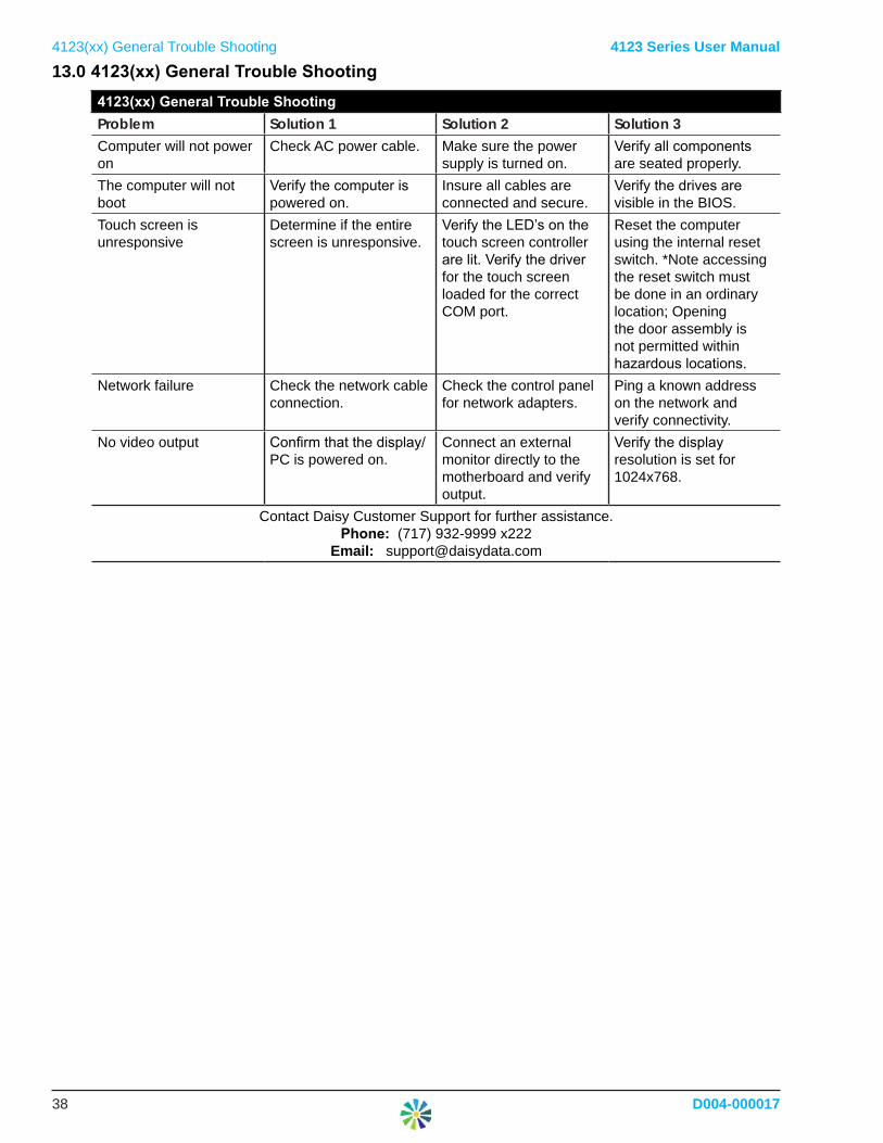
4123(xx) General Trouble Shooting 4123 Series User Manual13.0 4123(xx)GeneralTroubleShooting
4123(xx)GeneralTroubleShootingProblem Solution 1 Solution 2 Solution 3Computer will not power on
Check AC power cable. Make sure the power supply is turned on.
Verify all components are seated properly.
The computer will not boot
Verify the computer is powered on.
Insure all cables are connected and secure.
Verify the drives are visible in the BIOS.
Touch screen is unresponsive
Determine if the entire screen is unresponsive.
Verify the LED’s on the touch screen controller are lit. Verify the driver for the touch screen loaded for the correct COM port.
Reset the computer using the internal reset switch. *Note accessing the reset switch must be done in an ordinary location; Opening the door assembly is not permitted within hazardous locations.
Network failure Check the network cable connection.
Check the control panel for network adapters.
Ping a known address on the network and verify connectivity.
No video output Confirm that the display/PC is powered on.
Connect an external monitor directly to the motherboard and verify output.
Verify the display resolution is set for 1024x768.
Contact Daisy Customer Support for further assistance.Phone: (717) 932-9999 x222
Email: [email protected]
4123 Series User Manual
D004-000017 July2018
14.0 Revisions
Revision Description Date Author
- Initial Release 7/20/2018 BM