model 4280a imhz c meter/c-v plotter - oregon...
TRANSCRIPT

OPERATION AND SERVICE MANUAL
MODEL 4280A
IMHz C METER/C-V PLOTTER
(Including Option 001)
SERIAL NUMBERS
This manual applies directly to instruments with serial numbers prefixed 2346J.
With changes described in Section VII, this manual also applies to instruments with serial numbers prefixed 23 I5J.
For additional important information about serial numbers, see INSTRUMENTS COVERED BY MANUAL in Section I.
0 COPYRIGHT: YOKOGAWA-HEWLETT-PACKARD, LTD., 1983 9-1, TAKAKURA-CHO, HACHIOJI-SHI, TOKYO, JAPAN
I Manual Part No. 04280-90001 Microfiche Part No. 04280-90051 Printed: OCT. 1985


Model 4280A Table of Contents
TABLE OF CONTENTS
Section Title
I GENERAL INFORMATION
Page Section
3-38. 3-41.
;:;: Introduction . . . . . . . . . . . l-l Description . . . . . . . . . . . . l-l
l-10. Specifications . . . . . . . . . l-12. Safety Considerations . . . ;:; 1-15. Instruments Covered by
Manual . . . . . . . . . . . . . . l-3 l-20. Options . . . . . . . . . . . . . . . . 1-3 l-22. Option 001 . . . . . . . . . . . . . 1-3 1-23. Other Options . . . . . . . . . . l-3 l-24. Accessories Supplied . . . l-28 l-26. Accessories Available . . . l-28
3-43. 3-46. 3-48.
3-52. 3-54. 3-56.
3-58. 3-60.
II INSTALLATION 3-62.
g::: Introduction . . . . . . . . . . . 2-l Initial Inspection . . . . . 2-l
2-5. Preparation for Use . . . . 2-1 2-6. Power Requirements . . . . . 2-l 2-8. Line Voltage and Fuse
Selection . . . . . . . . . . . 2-l Z-10. Power Cable . . . . . . . . . . . . 2-l 2-14. Interconnections . . . . . . . 2-2 2-16. Operating Environment . . . 2-2 2-19. Installation
Instructions . . . . . . . . 2-4 2-21. Installation of Options
907, 908 and 909 . . . . 2-4 2-23. Storage and Shipment . . . 2-4 2-24. Environment . . . . . . . . . . . . 2-4 2-26. Packaging . . . . . . . . . . . . . . 2-4
3-64.
3-66. 3-68.
3-70. 3-72.
3-74. 3-76. 3-78. 3-80. 3-82. 3-84.
III OPERATION
3-l. Introduction . . . . . . . . . . . 3-l 3-3. Operating
3-5. 3-7. 3-9.
3-12. 3-17.
3-21. 3-23. 3-26. 3-29. 3-31. 3-33. 3-35.
Instructions . . . . . . . . 3-2 Panel Features . . . . . . . . . 3-2 Self Test . . . . . . . . . . . . . . 3-16 Measurement Functions
and Measurement Modes . . . . . . . . . . . . . . . 3-16
Displays . . . . . . . . . . . . . . . 3-17 Initial Display and
Control Settings . . . . 3-22 Error Codes . . . . . . . . . . . . 3-22 Test Signal . . . . . . . . . . . . 3-30 Measurement Speed . . . . . . 3-30 Measurement Ranges . . . . . 3-30 Connection Mode . . . . . . . . 3-30 UNKNOWN Terminals . . . . . . 3-33 How to Connect a Test
Sample . . . . . . . . . . . . . . 3-33
3-86. 3-88. 3-90. 3-92. 3-94. 3-96. 3-98. 3-100. 3-102.
3-104.
3-106.
3-108.
Title Page
Equivalent Circuits . . . . 3-34 Internal Error
Correction . . . . . . . . . . 3-35 MATH Function . . . . . . . . . . 3-36 Digit Shift . . . . . . . . . . . . 3-37 Internal DC Bias Source
Safety Features . . . . . 3-37 Usable Accessories . . . . . 3-38 External Triggering . . . . 3-39 External Error
Correction . . . . . . . . . . 3-39
C Mode . . . . . . . . . . . . . . . . . 3-40 Internal DC Bias
Source . . . . . . . . . . . 3-40 Internal DC Bias
Operation . . . . . . . . 3-40 Internal DC Bias
Source Output Limit and Range Control . . . . . . . . . . 3-41
External DC Bias . . . . 3-41 Measurement
Example . . . . . . . . . . 3-41
C-V Mode . . . . . . . . . . . . . . . 3-52 Bias Sweep
Parameters . . . . . . . 3-52 START V . . . . . . . . . . . . . 3-52 STOP V . . . . . . . . . . . . . . 3-52 STEP V . . . . . . . . . . . . . . 3-52 HOLD TIME . . . . . . . . . . . 3-56 STEP DELAY TIME . . . . . 3-56 C-V Mode Measurement
Example . . . . . . . . . . 3-56
C-t Mode . . . . . . . . . . . . . . . 3-62 C-t Parameters . . . . . . 3-62 PULSE V . . . . . . . . . . . . . 3-62 MEAS V . . . . . . . . . . . . . . 3-63 NO OF READINGS . . . . . . 3-63 th . . . . . . . . . . . . . . . . . . 3-63 td . . . . . . . . . . . . . . . . . . 3-63 Pulse Bias Source . . . 3-63 Connection Mode
Selection . . . . . . . . 3-64 DC Offset for Pulsed
Biasing . . . . . . . . . . 3-64
C-t Mode Measurement with Internally Supplied Bias Pulse . . . . . . . . . . . . 3-68
th (Pulse Bias Width) Setting Range . . . . 3-68
i

Table of Contents Model 4280A
TABLE OF CONTENTS
Section
3-110.
3-112.
3-114.
3-116.
3-118.
3-120.
3-122.
3-124.
3-126. 3-128.
3-130.
3-132.
3-134.
3-136.
3-139.
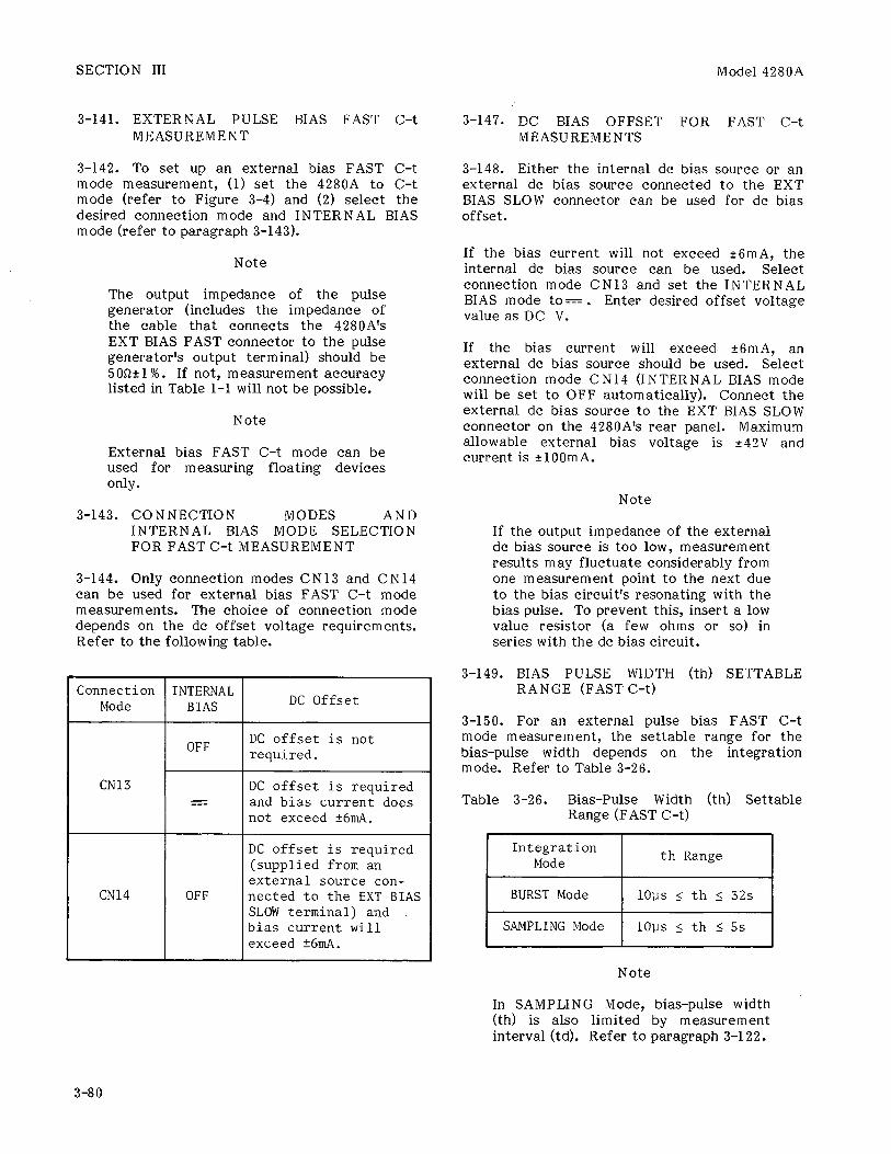
3-141.
3-143.
Title Page
td (Measurement Interval ) Setting Range . . . . . . . . . . .
External DC Offset of Internally Supplied Pulse Bias Voltage . . . .
Example of Internally Biased C-t Mode Measurement . . . . .
C-t Mode Measurement Using Externally Supplied Bias Pulse . . . . . . . . . . .
Measurement Integration Mode . . . . . . . . . . . .
BURST Integration Mode . . . . . . . . . . . .
SAMPLING Integration Mode . . . . . . . . . . . .
Using an External Pulse Generator for Pulse Biasing . . .
SYNC OUTPUT . . . . . . . . DC Offset of
Externally Supplied Pulse Bias Voltagee . . .
External Pulse Bias Slow c-t Measurement . . . . .
DC Bias Offset for SLOW c-t Measurements . . . .
Bias-Pulse Width (th) Settable Range (SLOW C-t) . . . . . .
Measurement Interval (td) Settable Range (SLOW C-t) . . . . . .
External Pulse Bias SLOW c-t Measurement Example . . . . . . . . .
External Pulse Bias FAST C-t Measurement . . . . .
Connection Modes and Internal Bias Mode Selection for FAST C-t Measurement . . . . .
3-68
3-68 3-151.
3-68
3-72
3-72
3-72
3-72
3-73 3-73
3-73
3-76
3-76
3-76
3-164. 3-166.
3-168. 3-170.
3-172. 3-174.
3-176. 3-178. 3-180. 3-182.
3-184. 3-186. 3-188. 3-190. 3-192. 3-194.
3-196.
3-76 3-198.
3-76
3-80
3-80
Section
3-147.
3-149.
3-154.
3-156. 3-161.
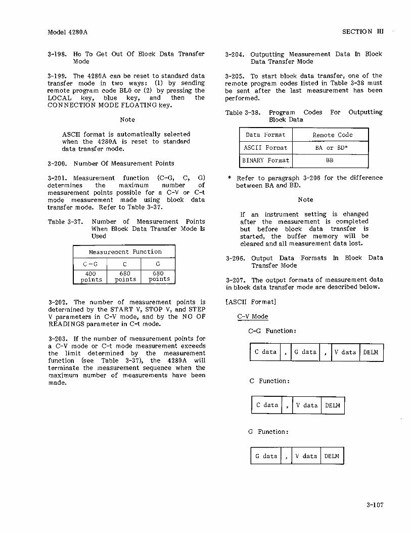
3-200.
3-204.
3-206.
3-208.
Title Page
DC Bias Offset for FAST C-t Measurements . . . . 3-80
Bias Pulse Width (th) Settable Range (FAST c-t) . . . . . . 3-80
Measurement Interval (td) Settable Range (FAST C-t) . . . . . . . . . . . . 3-81
External Pulse Bias FAST C-t Measure- ment Example . . . . 3-81
X-Y Recorder Outputs . . 3-84 C-High Resolution
(Option 001 Units Only) . . . . . . . . . . . . . . 3-88
HP-IB Interface . . . . . . . 3-92 HP-IB Interface
Capabilities . . . . . . . 3-92 Connection to HP-IB . . . 3-92 HP-IB Status
Indicators . . . . . . . . . 3-92 LOCAL Key . . . . . . . . . . . . . 3-92 HP-IB Address
Switches . . . . . . . . . . . 3-92 TALK ONLY Mode . . . . . . . . 3-93 ADDRESSABLE Mode . . . . . . 3-94 Remote Program Codes . . . 3-94 Setting Parameters
via the HP-IB . . . . . . 3-100 Data Output . . . . . . . . . . . 3-102 Output Data Format . . . . 3-102 ASCII Format . . . . . . . . . . 3-102 BINARY Format . . . . . . . . . 3-103 Data Transfer Mode . . . . 3-105
Block Data Transfer Mode . . . . . . . . . . . . 3-106
How to Get into Block Data Transfer Mode . . . 3-106
How to Get out of Block Data Transfer Mode . . . 3-106
Number of Measure- ment Points . . . . . 3-107
Outputting Measurement Data in Block Data Transfer Mode . . . 3-107
Output Data Formats in Block Data Transfer Mode . . . 3-107
Standard Data Transfer Mode . . . 3-108
ii

Model 4280A Table of Contents
TABLE OF CONTENTS
Section Title Page
3-210. Data Format in Standard Data Transfer Mode . . . 3-108
Output Data Formats in Standard Data Transfer Mode . . . 3-109
Isolate Function . . . . . . 3-111 Restrictions on Changing
Connection Modes . . . 3-111 LEARN Mode . . . . . . . . . . . . 3-111 Service Request Status
Byte . . . . . . . . . . . . . . . 3-116 4280A Programming
Guide . . . . . . . . . . . . . . 3-118
3-212.
3-214. 3-216.
3-218. 3-220.
3-222.
Appendix External Error Correction . . . . . . . A-l
IV PERFORMANCE TESTS
4-l. 4-3. 4-5. 4-7. 4-9.
4-l 1.
4-13.
4-19.
4-21.
4-23. 4-25.
Introduction . . . . . . . . . . Equipment Required . . . . Test Record . . . . . . . . . . . Calibration Cycle . . . . . Test Frequency Accuracy
Test . . . . . . . . . . . . . . . Test Signal Level
Accuracy Test . . . . . . Measurement Accuracy
Tests . . . . . . . . . . . . . . Internal Bias Voltage
Accuracy Test . . . . . . RECORDER OUTPUTS
Voltage Accuracy Test . . . . . . . . . . . . . . .
HP-IB Interface Test . . . Conductance Measurement
Accuracy Confirmation Check . . . . . . . . . . . . . .
4-l 4-l 4-l 4-l
4-7
4-8
4-9
4-15
4-17 4-18
Section
5-17.
5-19.
5-21. 5-23. 5-25.
5-27.
5-29.
5-31.
5-33.
5-35.
5-37.
5-39.
5-41.
5-43.
5-45.
5-47.
5-49.
5-51.
5-53.
Title Page
Al4 Switching Frequency Adjustment . . . . . . . . . . 5-6
All Reset Circuit Adjustment . . . . . . . . . . 5-7
Al4 +5V Adjustment . . . . . 5-9 A5 +12OV Adjustment . . . . 5-10 A4 Oscillator Level
Adjustment . . . . . . . . . . 5-11 A8 Integrator Offset
Adjustment . . . . . . . . . . 5-12 A8 Auto Zero
Adjustment . . . . . . . . . . 5-14 A8/A7 Test Signal
Phase Adjustment . . . . 5-15 A7 Tracking
Adjustment . . . . . . . . . . 5-17 A8 90' Phase
Adjustment . . . . . . . . . . 5-19 A8 S/H Gate
Adjustment . . . . . . . . . . 5-21 A2 DC Offset
Adjustment . . . . . . . . . . 5-23 A6 Loop Phase
Adjustment . . . . . . . . . . 5-25 A6 Bandpass Filter
Adjustment . . . . . . . . . . 5-28 A6 I-V Offset
Adjustment . . . . . . . . . . 5-29 A2 Range Resistor
Adjustment . . . . . . . . . . 5-30 A3 26dB L-R Amplifier
Adjustment . . . . . . . . . . 5-31 A4 DC Bias Supply
Adjustment . . . . . . . . . . 5-33 A10 Analog Output
Adjustment . . . . . . . . . . 5-35
VI REPLACEABLE PARTS 4-27
V ADJUSTMENTS
5-l. Introduction . . . . . . . . . . 5-l 5-3. Safety Requirements . . . 5-l 5-7. Equipment Required . . . . 5-l 5-9. Factory Selected
Components . . . . . . . . . 5-l 5-11. Adjustment
Relationships . . . . . . 5-5 5-13. Adjustment Locations . . . 5-5 5-15. Initial Operating
Procedure . . . . . . . . . . 5-5
6-l. Introduction . . . . . . . . . . . 6-l 6-3. Abbreviations . . . . . . . . . . 6-l 6-5. Replaceable Parts
List . . . . . . . . . . . . . . . . 6-l 6-7. Ordering Information . . . . 6-2 6-10. Direct Mail Order
System . . . . . . . . . . . . . . 6-2
VII MANUAL CHANGES
:::: Introduction ........... 7-l Manual Changes ......... 7-l
. . . 111

Table of Contents Model 4280A
TABLE OF CONTENTS
Section
VIII SERVICE
Title Page
8-l. 8-3.
8-5. 8-7.
8-9. 8-11. 8-13. 8-15. 8-17.
8-19.
8-25. 8-27.
8-28.
8-30. 8-33.
8-36. 8-40.
8-42. 8-45. 8-47. 8-49. 8-51. 8-53.
8-55. 8-57. 8-59.
Introduction ........... 8-l Safety
Considerations ...... 8-1 Theory of Operation .... 8-l Recommended Test
Equipment ........... 8-l Troubleshooting ........ 8-l Repair ................. 8-l Basic Theory ........... 8-2 Connection Modes ....... 8-2 Vector-Voltage-Current
Measurement ......... 8-2 Vector Voltage Ratio
Detector ............ 8-4 Digital Control ........ 8-5 Block Diagram
Discussion .......... 8-6 Analog Measurement
Section ............. 8-6 Signal Source .......... 8-6 Connection Mode
Switching Circuit .... 8-6 I-V Converter .......... 8-7 Vector Ratio
Detector ............ 8-9 Process Amplifier ...... 8-9 Phase Detector ......... 8-10 A-D Converter .......... 8-10 Auto-Zero Circuit ...... 8-10 Integrator ............. 8-10 Auto-Phase Adjust
Circuit ............. 8-11 Zero Cross Detector .... 8-11 Internal Bias Source .... 8-11 Option 001 C Offset
(Al board) .......... 8-12
iv

Model 4280 A List of Tables
LIST OF TABLES
Number Title Page
l-l. 1-2.
l-3.
3-l. 3-2. 3-3. 3-4. 3-5.
3-6. 3-7.
;:;:
3-12. 3-13. 3-14. 3-15. 3-16. 3-17.
3-19. 3-20.
3-22.
3-23.
3-25.
3-26.
3-28.
3-29.
3-30.
3-31. 3-32.
3-33.
3-34. 3-35.
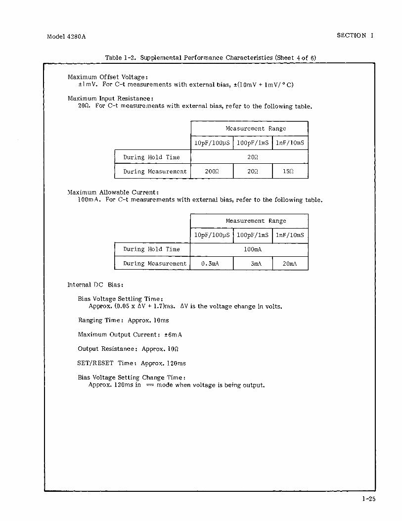
Specifications ............. l-4 Supplemental Performance
Characteristics ......... l-22 Accessories Available ...... l-29
Power on Self Test ......... 3-18 Standard Self Test ......... 3-18 Overflow Annunciations ..... 3-23 Operation Error Codes ...... 3-23 Dissipation Factor
Equations and Equivalent Circuit Conversion Formulas ................ 3-34
Usable Accessories ......... 3-38 Internal DC Bias Source
Ranges .................. 3-40 Auto-Ranging Mode .......... 3-40 Internal DC Bias Source
V LIMIT vs Range ........ 3-41 START V Resolution ......... 3-52 STEP V Resolution .......... 3-52 HOLD TIME Resolution ....... 3-56 PULSE V Resolution ......... 3-62 th Resolution .............. 3-63 Connection Mode
Selection ............... 3-64 td Setting Range ............ 3-68 Connection Modes for SLOW
and FAST C-t Mode Measurements ............ 3-72
DC Offset of External Pulse voltage ........... 3-73
Bias-Pulse Width (th) Settable Range (SLOW C-t) .................... 3-76
Measurement Interval (td) Settable Range (SLOW C-t) ............... 3-77
Bias-Pulse Width (th) Settable Range (FAST C-t) .................... 3-80
Measurement Interval (td) Settable Range (FAST C-t) .............. 3-81
Usable Ranges for C-HIGH RESOLN .................. 3-88
HP-IB Interface Capabilities ............ 3-92
HP-IB Mode Selection ....... 3-93 Output Data Delimiters -
TALK ONLY Mode (51) ..... 3-93 Output Data Format -
TALK ONLY Mode .......... 3-94 Remote Program Codes ....... 3-95 Remote Program Codes for
Measurement Parameters .............. 3-99
Number
3-36.
3-37.
3-38.
3-39.
3-40. 3-41. 3-42.
4-l. 4-2.
4-3.
4-4. 4-5.
4-6.
4-7.
4-8.
4-9.
4-10.
4-11.
4-12.
5-l. 5-2.
5-3.
6-1.
6-2. 6-3.
7-l.
7-2.
Title Page
Output Data Transfer Modes and Formats . . . . . . . . . . . . . 3-102
Number of Measurement Points When Block Data Transfer Mode Is Used . . . . . . . . . . . . . . . . . . . . 3-107
Program Codes for Outputting Block Data . . . . . . . . . . . . . . . . . . . . 3-107
Data Format Program Codes . . . . . . . . . . . . . . . . . . . 3-108
LEARN Mode . . . . . . . . . . . . . . . . . 3-112 Sample Programs . . . . . . . . . . . . 3-118 Data Transmission Times . . . . 3-118
Recommended Equipment . . . . . . 4-A Test Frequency Accuracy
Test Limits . . . . . . . . . . . . . 4-7 Test Signal Level Accuracy
Test Limits . . . . . . . . . . . . . 4-8 Open Test Limits . . . . . . . . . . . 4-9 Capacitance Standard
Test Limits (CNlO) . . . . . . 4-11 Capacitance Standard Test
Limits (CN13) . . . . . . . . . . . 4-12 Capacitance Standard Test
Limits (CN15) . . . . . . . . . . . 4-14 Internal Bias Voltage
Accuracy Test Limits . . . . 4-16 RECORDER OUTPUTS Voltage
Accuracy Test Limits . . . . 4-17 Controller Instructions
and Operator Responses for Test Program 1 . . . . . . 4-21
Controller Instructions and Operator Responses for Test Program 2 . . . . . . 4-23
Controller Instructions and Operator Responses for Test Program 3 . . . . . . 4-26
Adjustable Components . . . . . . 5-2 Factory Selected
Components . . . . . . . . . . . . . . 5-4 Adjustment Requirements . . . . 5-5
List of Reference Designators and Abbreviations . . . . . . . . . . . 6-1
Manufacturers Code Lists . . . . 6-2 Replaceable Parts . . . . . . . . . . 6-3
Manual Change by Serial Number . . . . . . . . . . . . . . . . . . 7-l
Summary of Changes by Assembly . . . . . . . . . . . . . . . . 7-2
V

List of Illustrations Model 4280A
LIST OF ILLUSTRATIONS
Number
l-l.
l-2.
2-l.
2-2. 2-3.
;::: 3-3. 3-4.
3-5.
3-6.
3-7. 3-8. 3-9.
3-10.
3-11.
3-12.
3-13.
3-15.
3-16.
Title Page
Model 4280A and Accessories . . . . . . . . . . . . . . l-l
Serial Number Plate . . . . . . . . l-3
Voltage and Fuse Selection . . . . . . . . . . . . . . . . 2-2
Power Cables Supplied . . . . . . 2-3 Rack Mount Kit . . . . . . . . . . . . . 2-5
Contents of Section III . . . . 3-l Front Panel Features . . . . . . . 3-2 Rear Panel Features . . . . . . . . 3-14 Interchanging Measurement
Functions and Measurement Modes . . . . . . . . 3-19
Maximum Display Value, Display Digits, and Resolution for the C Display . . . . . . . . . . . . . . . . . . 3-20
Maximum Display Value, Display Digits, and Resolution for the G Display . . . . . . . . . . . . . . . . . . 3-21
AUTO Ranging Operation . . . . . 3-31 Connection Modes . . . . . . . . . . . 3-32 Two-Terminal Pair
Configuration . . . . . . . . . . . . 3-33 Floating Test Sample
Connection . . . . . . . . . . . . . . . 3-33 Grounded Test Sample
Connection . . . . . . . . . . . . . . . 3-33 Connection Using a Wafer
Prober . . . . . . . . . . . . . . . . . . . 3-32 External Triggering
Signal . . . . . . . . . . . . . . . . . . . 3-39 Procedure for Setting
Interna 1 DC Bias Voltage . . . . . . . . . . . . . . . . . . 3-42
Procedure for Setting V LIMIT . . . . . . . . . . . . . . . . . . . . 3-42
3-17(a). External DC Bias Application up to +142V . . . . . . . . . . . . . . . . . . . . 3-43
3-17(b). External DC Bias Application up to ?2OOV . . . . . . . . . . . . . . . ...*. 3-44
3-18. C Mode Measurement Example . . . . . . . . . . . . . . . . . . 3-46
3-19. HP-19 Controlled C Mode Measurement Example . . . . . . 3-48
3-20. Bias Sweep Set-up Procedure . . . . . . . . . . . . . . . . 3-54
3-21. C-V Mode Measurement Example . . . . . . . . . . . . . . . . . . 3-57
3-22. HP-19 Controlled C-V Mode Measurement Example . . . . . . 3-59
vi
Number
3-23.
3-25.
3-26.
3-27. 3-28.
3-29.
3-30.
3-31.
3-32.
3-33.
3-34.
3-35.
3-36. 3-37. 3-38. 3-39.
3-40.
3-41. 3-42.
4-l.
4-2.
4-3. 4-4.
4-5.
4-6.
4-7.
Title Page
Procedure for Setting C-t Mode Parameters . . . . . . . . .
Internal Pulse Bias C-t Mode Measurement Example . . . . . . . . . . :. . . . . .
HP-19 Controlled Internal Pulse Bias C-t Mode Measurement Example . . . . .
BURST Integration Mode . . . . . SAMPLING Integration
Mode . . . . . . . . . . . . . . . . . . . . External Pulse Generator
Connection . . . . . . . . . . . . . . Pulse Generator Output
Controlled by SYNC OUTPUT Signal . . . . . . . . . . .
External Pulse Bias SLOW C-t Measurement Example . . . . . . . . . . . . . . . . .
HP-19 Controlled External Pulse Bias SLOW C-t Measurement Example
External Pulse Bias FAST""' C-t Measurement Example . . . . . . . . . . . . . . . . .
HP-19 Controlled External Pulse Bias FAST C-t Measurement Example . . . . .
Procedure for Setting up an X-Y Recorder to Plot c-v Characteristics . . . . . . . . .
C-HIGH RESOLN Function . . . . . HP-19 Address Switches . . . . . Block Data Transfer Mode . . . . Standard Data Transfer
Mode . . . . . . . . . . . . . . . . . . . . LEARN Mode Program
Example . . . . . . . . . . . . . . . . . 4280A Status Byte . . . . . . . . . . Sample Programs . . . . . . . . . . . .
Test Frequency Accuracy Test Setup . . . . . . . . . . . . . .
Test Signal Level Accuracy Test Setup . . . . . . . . . . . . . .
Open Test Setup . . . . . . . . . . . . Capacitance Standard Test
Setup (CNlO) . . . . . . . . . . . . Capacitance Standard Test
Setup (CN15) . . . . . . . . . . . . Internal Bias Voltage
Accuracy Test Setup . . . . . RECORDER OUTPUTS Voltage
Accuracy Test Setup . . . . .
3-65
3-69
3-70 3-74
3-75
3-73
3-73
3-78
3-79
3-82
3-83
3-86 3-90 3-93
3-106
3-109
3-112 3-116 3-120
4-7
4-8 4-9
4-10
4-13
4-15
4-17

Model 4280A
LIST OF ILLUSTRATIONS
List of illustrations
Number
4-8.
4-9.
5-l.
5-2.
5-3. 5-4.
5-5.
5-6.
5-7.
5-8.
5-9.
5-10.
5-11.
5-12.
5-13.
5-14. 5-15.
5-16.
5-17.
5-18.
Title Page
HP-IB Interface Test Setup . . . . . . . . . . . . . . . . . . . . 4-18
Conductance Measurement Accuracy Confirmation Check Setup . . . . . . . . . . . . . . 4-27
Al4 Switching Frequency Adjustment Setup . . . . . . . . . 5-6
Reset Circuit Adjustment Setup . . . . . . . . . . . . . . . . . . . . 5-7
Al4 +5V Adjustment Setup . . . . . 5-9 A5 +12OV Adjustment
Setup . . . . . . . . . . . . . . . . . . . . 5-10 A4 Oscillator Level
Adjustment Setup . . . . . . . . . 5-11 A8 Integrator Offset
Adjustment Setup . . . . . . . . . 5-12 Waveform at A8TP4 (SLOPE
AMP OUT) . . . . . . . . . . . . . . . . . 5-13 A8/A7 Test Signal Phase
Adjustment Setup . . . . . . . . . 5-15 A7 Tracking Adjustment
Setup . . . . . . . . . . . . . . . . . . . . 5-17 A8 90" Phase Adjustment
Setup . . . . . . . . . . . . . . . . . . . . 5-19 A8 S/H Gate Adjustment
Setup . . . . . . . . . . . . . . . . . . . . 5-21 A2 DC Offset Adjustment
Setup . . . . . . . . . . . . . . . . . . . . 5-23 A6 Loop Phase Adjustment
Setup . . . . . . . . . . . . . . . . . . . . 5-25 Waveform at A6TPll . . . . . . . . . . 5-27 A2 Range Resistor
Adjustment Setup . . . . . . . . . 5-30 A3 26dB L-R Amplifier
Adjustment Setup . . . . . . . . . 5-31 A4 DC Bias Supply
Adjustment Setup . . . . . . . . . 5-33 A10 Analog Output
Adjustment Setup . . . . . . . . . 5-35
Number
8-l. 8-2.
;I;:
8-5.
8-6.
8-7.
8-8.
8-9.
8-10.
8-11.
8-12.
Title Page
4280A Block Diagram . . . . . . . . . 8-2 Basic Connection Modes . . . . . . 8-3 I-V Converter . . . . . . . . . . . . . . . 8-3 Phase Detection Vector
Diagram . . . . . . . . . . . . . . . . . . 8-4 Vector Voltage Ratio
Detection Timing . . . . . . . . . 8-5 Signal Source Block
Diagram . . . . . . . . . . . . . . . . . . 8-6 Connection Mode Switching
Circuit Block Diagram . . . . . 8-7 I-V Converter Block
Diagram . . . . . . . . . . . . . . . . . . 8-8 Vector Representation of
the Vector Modulator outputs . . . . . . . . . . . . . . . . . . 8-9
Vector Ratio Detector Block Diagram . . . . . . . . . . . . 8-10
Internal Bias Source Block Diagram . . . . . . . . . . . . 8-11
Al C Offset Block Diagram . . . . . . . . . . . . . . . . . . 8-12
vii