model 6400 torque transducer display - magtrol
TRANSCRIPT

MODEL 6400
Torque Transducer Display
User’s Manual

3rd Edition, revision B – June 2004
While every precaution has been exercised in the compilation of this document toensure the accuracy of its contents, Magtrol, Inc. assumes no responsibility for errorsor omissions. Additionally, no liability is assumed for any damages that may resultfrom the use of the information contained within this publication.
COPYRIGHTCopyright ©2000-2004 Magtrol, Inc. All rights reserved.Copying or reproduction of all or any part of the contents of this manual without theexpress permission of Magtrol is strictly prohibited.
TRADEMARKSLabVIEW™ is a trademark of National Instruments Corporation.National Instruments™ is a trademark of National Instruments Corporation.Windows® is a registered trademark of Microsoft Corporation.

i
1. Make sure that all Magtrol Torque Transducers and electronic products are earth-grounded, toensure personal safety and proper operation.
2. Securely ground the 6400 Torque Transducer Display case by connecting a good earth groundat the ground stud located on the rear panel of the unit. Use a number 12 AWG, or larger wire.
3. Check line voltage before operating.
4. Make sure that torque transducers and motors under test are equipped with appropriate safetyguards.
Safety Precautions
STOPSTOP

ii
The contents of this manual are subject to change without prior notice. Should revisions be necessary, updates to allMagtrol User’s Manuals can be found at Magtrol’s web site at www.magtrol.com/support/manuals.htm.
Please compare the date of this manual with the revision date on the web site, then refer to the manual’s Table ofRevisions for any changes/updates that have been made since this edition.
REVISION DATE
3rd Edition, revision B – June 2004
TABLE OF REVISIONS
Revisions To This Manual
etaD noitidE egnahC )s(noitceS
40/01/60 B.ver,noitidEdr3 metsysnoitisiuqcaatadrofstuptuodeepsdnaeuqrotdeddA 5.2,4.2,3.1
40/01/60 B.ver,noitidEdr3 sgniwardcitamehcsdetadpU 4.C–1.C
30/91/90 A.ver,noitidEdr3 sgniwardcitamehcsdetadpU 3.Cdna1.C
10/80/11 noitidEdr3 sgniwardyalpsiddedulcnidnaliatederomdeddA lla
10/71/80 noitidEdn2 deretlanusawtnetnoc-launameritnefognittamrofeR lla

iii
Table of Contents
SAFETY PRECAUTIONS ......................................................................................................................... i
REVISIONS TO THIS MANUAL............................................................................................................... iiREVISION DATE ................................................................................................................................................................. ii
TABLE OF REVISIONS ...................................................................................................................................................... ii
TABLE OF CONTENTS ......................................................................................................................... iiiTABLE OF FIGURES .......................................................................................................................................................... v
PREFACE ............................................................................................................................................... viPURPOSE OF THIS MANUAL .......................................................................................................................................... vi
WHO SHOULD USE THIS MANUAL............................................................................................................................... vi
MANUAL ORGANIZATION .............................................................................................................................................. vi
CONVENTIONS USED IN THIS MANUAL ................................................................................................................... vii
1. INTRODUCTION ................................................................................................................................ 11.1 UNPACKING YOUR 6400 TORQUE TRANSDUCER DISPLAY .............................................................................. 1
1.2 FEATURES OF THE 6400 TORQUE TRANSDUCER DISPLAY .............................................................................. 1
1.3 DATA SHEET ................................................................................................................................................................ 3
2. CONTROLS ........................................................................................................................................ 52.1 FRONT PANEL ............................................................................................................................................................. 5
2.2 FRONT PANEL CONTROLS AND BUTTONS .......................................................................................................... 52.2.1 Enabling Secondary Functions ........................................................................................................................ 52.2.2 Using Front Panel Controls and Buttons ......................................................................................................... 6
2.3 VACUUM FLUORESCENT DISPLAY (VFD) ............................................................................................................ 72.3.1 Contrast Settings .............................................................................................................................................. 7
2.4 REAR PANEL ............................................................................................................................................................... 8
2.5 REAR PANEL INPUTS AND OUTPUTS .................................................................................................................... 8
3. INSTALLATION/CONFIGURATION ................................................................................................. 103.1 POWERING UP THE 6400 ......................................................................................................................................... 10
3.1.1 Setting Unit for Line Voltage ......................................................................................................................... 103.1.2 Self-Test ......................................................................................................................................................... 103.1.3 Main Menu .................................................................................................................................................... 12
4. MANUALLY CONTROLLED OPERATION....................................................................................... 134.1 SETTING DESIRED OPERATING PARAMETERS ................................................................................................. 13
4.1.1 Power Units Setup ......................................................................................................................................... 134.1.2 Torque Units Setup ........................................................................................................................................ 134.1.3 System Parameter Setup ................................................................................................................................ 144.1.4 Auxiliary Scale Factor Setup ......................................................................................................................... 164.1.5 Pass/Fail Parameter Setup .............................................................................................................................. 174.1.6 Input/Output (I/O) Parameter Setup .............................................................................................................. 19
4.2 USING INTERNAL MEMORY .................................................................................................................................. 194.2.1 Storing Data Points ........................................................................................................................................ 194.2.2 Recalling Data Points .................................................................................................................................... 204.2.3 Exiting the Memory Mode ............................................................................................................................ 204.2.4 Clearing the Memory ..................................................................................................................................... 20
4.3. USING THE TARE FUNCTION ................................................................................................................................ 20
4.4 SYSTEM TEST............................................................................................................................................................ 21

iv
Magtrol Model 6400 Torque Transducer DisplayTable of Contents
5. COMPUTER CONTROLLED OPERATION...................................................................................... 225.1 ABOUT THE GPIB INTERFACE ............................................................................................................................... 22
5.1.1 Connecting the GPIB (IEEE-488) Cable ....................................................................................................... 225.1.2 Changing the GPIB Primary Address ............................................................................................................ 23
5.2 ABOUT THE RS-232 INTERFACE ............................................................................................................................ 235.2.1 Connection ..................................................................................................................................................... 235.2.2 Communication Parameters ........................................................................................................................... 245.2.3 Baud Rate ....................................................................................................................................................... 24
5.3 CHECKING THE 6400-TO-PC CONNECTION ........................................................................................................ 24
5.4 DATA FORMAT .......................................................................................................................................................... 25
5.5 PROGRAMMING........................................................................................................................................................ 265.5.1 Data Termination Characters ......................................................................................................................... 265.4.2 Timeout .......................................................................................................................................................... 26
5.6 6400 COMMAND SET ............................................................................................................................................... 275.6.1 Communication Commands .......................................................................................................................... 275.6.2 Setup Commands ........................................................................................................................................... 285.6.3 Calibration Commands .................................................................................................................................. 29
6. CALIBRATION .................................................................................................................................. 306.1 CLOSED-BOX CALIBRATION ................................................................................................................................. 30
6.2 CALIBRATION SCHEDULE ..................................................................................................................................... 30
6.3 BASIC CALIBRATION PROCESS ............................................................................................................................ 306.3.1 Initial Calibration Procedure ......................................................................................................................... 306.3.2 Torque Offset and Gain .................................................................................................................................. 316.3.3 Auxiliary Input Offset and Gain .................................................................................................................... 32
7. TROUBLESHOOTING ...................................................................................................................... 34
APPENDIX A: LABVIEW PROGRAMMING EXAMPLES .................................................................... 35A.1 SIMPLE READ ............................................................................................................................................................ 35
APPENDIX B: FRONT PANEL/DISPLAY MENU FLOW CHARTS ...................................................... 36B.1 SETUP MENU ............................................................................................................................................................. 36
B.2 TORQUE UNITS MENU ............................................................................................................................................ 37
B.3 AUX SETUP MENU ................................................................................................................................................... 38
B.4 POWER UNITS MENU .............................................................................................................................................. 38
APPENDIX C: SCHEMATICS................................................................................................................ 39C.1 ANALOG SECTION ................................................................................................................................................... 39
C.2 CPU SECTION ............................................................................................................................................................ 40
C.3 INPUT/OUTPUT (I/O) SECTION .............................................................................................................................. 41
C.4 POWER SUPPLY SECTION ....................................................................................................................................... 42
C.5 KEYPAD ...................................................................................................................................................................... 43
INDEX .................................................................................................................................................... 44
MAGTROL LIMITED WARRANTY ........................................................................................................ 46CLAIMS .............................................................................................................................................................................. 46

v
Magtrol Model 6400 Torque Transducer Display Table of Contents
TABLE OF FIGURES
CHAPTER 2Figure 2–1 Front Panel ............................................................................................................................................. 5Figure 2–2 Contrast Setup Menu .............................................................................................................................. 7Figure 2–3 Rear Panel .............................................................................................................................................. 8Figure 2–4 Torque Meter Connector ........................................................................................................................ 8Figure 2–5 RS-232C Interface .................................................................................................................................. 8Figure 2–6 GPIB/IEEE-488 Interface ...................................................................................................................... 9
CHAPTER 3Figure 3–1 Cable and Connection Diagrams ......................................................................................................... 11Figure 3–2 Program Download Display ................................................................................................................. 11Figure 3–3 Title Display ......................................................................................................................................... 11Figure 3–4 Revision Display ................................................................................................................................... 12Figure 3–5 Main Menu ........................................................................................................................................... 12
CHAPTER 4Figure 4–1 Power Units Setup Menu ...................................................................................................................... 13Figure 4–2 Torque Units Setup Menu ..................................................................................................................... 13Figure 4–3 Max Power Setup Display .................................................................................................................... 14Figure 4–4 Power Overload Display ...................................................................................................................... 14Figure 4–5 Direction Input Setup Menu ................................................................................................................. 15Figure 4–6 Encoder Setup Display ......................................................................................................................... 15Figure 4–7 Torque Scale Factor Setup Display ...................................................................................................... 16Figure 4–8 Auxiliary Scale Factor Setup Display ................................................................................................... 16Figure 4–9 Torque Pass/Fail Setup Menu ............................................................................................................... 17Figure 4–10 High Limit Setup Display ..................................................................................................................... 17Figure 4–11 Low Limit Setup Display ...................................................................................................................... 17Figure 4–12 Speed Pass/Fail Setup Menu ................................................................................................................. 18Figure 4–13 Auxiliary Input Pass/Fail Setup Menu .................................................................................................. 18Figure 4–14 Pass/Fail Display Example ................................................................................................................... 18Figure 4–15 GPIB Address Setup Menu ................................................................................................................... 19Figure 4–16 RS-232 Baud Rate Setup Menu ............................................................................................................ 19Figure 4–17 Store Display ........................................................................................................................................ 19Figure 4–18 Recall Display ...................................................................................................................................... 20Figure 4–19 Main Menu with Recall Function Enabled .......................................................................................... 20Figure 4–20 Torque Transducer at Full Scale .......................................................................................................... 21
CHAPTER 5Figure 5–1 GPIB Installation ................................................................................................................................. 22Figure 5–2 RS-232 Interface ................................................................................................................................... 23Figure 5–3 Cable Connection Using Null Modem ................................................................................................. 23
CHAPTER 6Figure 6–1 Software Revision Date Display ........................................................................................................... 31Figure 6–2 Torque Offset and Gain Display ........................................................................................................... 31Figure 6–3 Zero Torque Display ............................................................................................................................. 31Figure 6–4 Full Scale Torque Display 1 ................................................................................................................. 32Figure 6–5 Full Scale Torque Display 2 ................................................................................................................. 32
vi
PURPOSE OF THIS MANUAL
This manual contains all the information required for the installation and general use of the Model6400 Torque Transducer Display. To achieve maximum capability and ensure proper use of theinstrument, please read this manual in its entirety before operating. Keep the manual in a safe placefor quick reference whenever a question should arise.
WHO SHOULD USE THIS MANUAL
This manual is intended for bench test operators who are going to use the 6400 Torque TransducerDisplay in conjunction with any Magtrol In-Line Torque Transducer.
MANUAL ORGANIZATION
This section gives an overview of the structure of the manual and the information contained withinit. Some information has been deliberately repeated in different sections of the document to minimizecross-referencing and to facilitate understanding through reiteration.
The structure of the manual is as follows:
Chapter 1: INTRODUCTION - Contains the technical data sheet for the 6400 Torque TransducerDisplay, which describes the unit and provides its mechanical and electricalcharacteristics.
Chapter 2: CONTROLS - Description of the elements located on the front and rear panels ofthe unit.
Chapter 3: INSTALLATION/CONFIGURATION - Provides information needed for setup ofthe 6400.
Chapter 4: MANUALLY CONTROLLED OPERATION - How to run a test when the 6400 isused as a stand-alone unit. Includes information on setting operating parametersand using internal memory.
Chapter 5: COMPUTER CONTROLLED OPERATION - How to run a test when the 6400 isused with a personal computer. Includes information on GPIB (IEEE-488) andSerial (RS-232) interface, data format, programming and command set.
Chapter 6: CALIBRATION - Provides recommended calibration schedules along with step-by-step instructions for the calibration procedure.
Chapter 7: TROUBLESHOOTING - Solutions to common problems encountered during setupand testing.
Appendix A: LABVIEW™ PROGRAMMING EXAMPLES - Example of communicating withthe 6400 when writing your own software.
Appendix B: FRONT PANEL/DISPLAY MENU FLOW CHARTS - A visual display of varioussetup procedures.
Appendix C: SCHEMATICS - For the analog, CPU, I/O, power supply and keypad sections.
Glossary: List of abbreviations and terms used in this manual, along with their definitions.
Preface
vii
Magtrol Model 6400 Torque Transducer Display Preface
CONVENTIONS USED IN THIS MANUAL
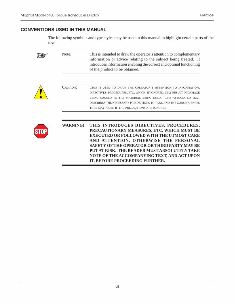
The following symbols and type styles may be used in this manual to highlight certain parts of thetext:
Note: This is intended to draw the operator’s attention to complementaryinformation or advice relating to the subject being treated. Itintroduces information enabling the correct and optimal functioningof the product to be obtained.
CAUTION: THIS IS USED TO DRAW THE OPERATOR’S ATTENTION TO INFORMATION,DIRECTIVES, PROCEDURES, ETC. WHICH, IF IGNORED, MAY RESULT IN DAMAGE
BEING CAUSED TO THE MATERIAL BEING USED. THE ASSOCIATED TEXT
DESCRIBES THE NECESSARY PRECAUTIONS TO TAKE AND THE CONSEQUENCES
THAT MAY ARISE IF THE PRECAUTIONS ARE IGNORED.
WARNING! THIS INTRODUCES DIRECTIVES, PROCEDURES,PRECAUTIONARY MEASURES, ETC. WHICH MUST BEEXECUTED OR FOLLOWED WITH THE UTMOST CAREAND ATTENTION, OTHERWISE THE PERSONALSAFETY OF THE OPERATOR OR THIRD PARTY MAY BEPUT AT RISK. THE READER MUST ABSOLUTELY TAKENOTE OF THE ACCOMPANYING TEXT, AND ACT UPONIT, BEFORE PROCEEDING FURTHER.
STOPSTOP

1
GE
NE
RA
LIN
FO
RM
AT
ION
Calibration Certificate
1. Introduction
2. Inspect the contents for any evidence of damage in shipping. In the event of shipping damage,immediately notify the carrier and Magtrol's Customer Service Department.
Note: Save all shipping cartons and packaging material for reuse whenreturning the instrument for calibration or servicing.
1.2 FEATURES OF THE 6400 TORQUE TRANSDUCER DISPLAY
Designed specifically for use with Magtrol's In-Line Torque Transducers, the new Model 6400Torque Transducer Display powers the transducer and utilizes high speed digital signal processingto display torque, speed, mechanical power and direction of rotation. The 6400 can be used as abasic display, as an interface with Magtrol TM Software or on the production line. Its featuresinclude:
• High Quality, Easy-to-Read Display: Vacuum fluorescent readout with large digits.
• High-Speed Data Acquisition: 100 torque and speed readings per second via IEEE (GPIB)bus.
1.1 UNPACKING YOUR 6400 TORQUE TRANSDUCER DISPLAYYour 6400 Torque Transducer Display was packaged in reusable, shock resistant packing materialthat will protect the instrument during normal handling.
1. Make sure the carton contains the following:
POWER UNITS TORQUE UNITS AUX SETUP CLR MEM SETUP SHIFTADJUST
TARE UNITS DISPLAY DISPLAY STORE RECALL
MODEL 6400DISPLAY
POWER
POWER/AUX TORQUE SPEED
6400 Torque Transducer Display Line cord
MagtrolUser Manual
CD-Rom

2
Magtrol Model 6400 Torque Transducer DisplayChapter 1 – Introduction
GE
NE
RA
LIN
FO
RM
AT
ION
• Pass/Fail Testing: Upper and lower limits are programmable for torque, speed, and auxiliaryinput.
• Internal Data Storage: Nonvolatile memory of up to 100 data points.
• Overload Protection: Maximum power limit can be programmed to warn user of overloadcondition.
• Two Standard Computer Interfaces: RS-232 and IEEE-488.
• Additional Analog Input: Accepts any ± 10 VDC transducer.
• Torque Measurement Options: Standard English, metric and SI settings.
• Closed-Box Calibration of Torque and Auxiliary Input: Eliminates need to open boxfor adjustments.

3
Magtrol Model 6400 Torque Transducer Display Chapter 1 – Introduction
GE
NE
RA
LIN
FO
RM
AT
ION
1.3 DATA SHEET
Model 6400 TorqueTransdu ce r Displa y
MODEL 6400TORQUE TRANSDUCER DISPLAY
Power Supply (AC)Model64006400A
±10 VDCAuxiliary Input
Device
Data AcquisitionSystem
Input Power120V/60Hz240V/50 Hz
TM, TMHS or TMB SeriesTorque Transducer
GPIB
RS-232 PCTM Software
or
RS-232CGPIB/IEEE–488
CAUTION: DOUBLE POLE FUSING16VA 50/60Hz
EARTHGROUND
FUSE (5×20mm):120V UL/CSA 200mA 250V SB240V IEC 80mA 250V TMAGTROL, INC. BUFFALO, NY
TORQUE METERAUX.
INPUT
TORQUE SPEED
SYSTEM CONFIGURATION
FEATURES• For use with all Magtrol TM, TMHS and TMB Torque
Transducers
• Pass/Fail Testing for torque, speed and auxiliary input
• BITE: Built-In Test Equipment
• RS-232 & IEEE-488 Interfaces
• High Speed Data Acquisition: 100 torque and speed readings per second via IEEE bus
• High Quality, Easy-to-Read Vacuum Fluorescent Readout: Displays torque, speed, power and direction of rotation
• Torque Measurement Options: Standard English, metric and SI settings
• Overload Indication
• Tare Function
• Internal Data Storage: Up to 100 data points
• Auxiliary ± 10 VDC Analog Input for additional transducer
• Access to TM signals via back panel BNC connectors
• Interfaces with Magtrol TM Software
• Closed Box Calibration
• 19" (482.6 mm) Rack Mounts with Handles
DESCRIPTIONMagtrol’s Model 6400 Torque Transducer Display is designed specifically for use with all TM, TMHS and TMB Torque Transducers. This easy-to-use device powers the transducer and utilizes high speed Digital Signal Processing (DSP) to display torque, speed, mechanical power and direction of rotation.
The 6400 can be used as a basic display, as an interface with Magtrol TM Software or on the production line using its pass/fail feature. The unit includes an auxiliary analog input for the option of testing with an additional transducer and a special tare function to help offset any slight residuals caused by couplings or suspended loads. The 6400 also has IEEE-488 and RS-232 interface capabilities, allowing a PC-controlled environment that can yield high data acquisition rates of up to 100 torque and speed readings per second. With Magtrol's TM Software (sold separately), the data for torque, speed and mechanical power can be automatically collected, saved, displayed graphically, printed or exported.
PASS/FAIL MOTOR TESTINGThe Model 6400 comes with an easy-to-use motor testing Pass/Fail feature. This feature is ideal for quick pass/fail (go/no go) testing in production and incoming inspection applications.
When the 6400 is operated in the Pass/Fail mode, one of three readings is used as the tested parameter: torque, speed or auxiliary transducer. The two parameters not used are set with user defined upper and lower acceptable limits. As the motor is loaded to the tested parameter value (for example, speed), the other two parameters (in this case, torque and transducer) will indicate PASS or FAIL. The display will show pass or fail, or can be toggled to display the actual values.

4
Magtrol Model 6400 Torque Transducer DisplayChapter 1 – Introduction
GE
NE
RA
LIN
FO
RM
AT
ION
6400
Due to the continual development of our products, we reserve the right to modify specifi cations without forewarning.
S pecifications
6400
-US
ww
w 0
6/04
SYSTEM OPTIONS/ACCESSORIES
MEASUREMENT CHARACTERISTICS
AccuracySpeedTorque
Aux
0.01% of reading from 10 rpm to 100,000 rpm0.1% of range (± 10 V)0.1% of range (± 10 V)
Maximum Speed 99,999 rpmELECTRICAL CHARACTERISTICS
Fuses (5 × 20 mm)Power (120 V): 200 mA UL/CSA 250 V SBPower (240 V): 80 mA IEC 250 V T
Power Requirements 16 VAVoltage Requirements 120/240 V 60/50 HzINPUTS AND OUTPUTSAuxiliary Input ± 10 VDCMaximum Torque Input ± 10 VDCTorque Output BNC ±10 VDC (direct from TM)Speed Output BNC 0 to 5 VDC pulse (direct from TM)
Description Model/Part #Torque Transducer Software SW-TM-WETransducer Software with source codes SW-TM-WSTorque Transducer Connector Cable-5/10/20 m ER 113-01/02/03
ENVIRONMENTAL CHARACTERISTICSOperating Temperature 18 ºC to 25 ºCRelative Humidity < 80%Temperature Coefficient 0.001% of range/°CMECHANICAL CHARACTERISTICSWidth 19.0 in 483 mmDepth 12.4 in 315 mmDepth with handles 13.8 in 351 mmHeight 3.5 in 89 mmWeight 14.5 lb 6.58 kg
RS-232 and GPIB/IEEE-488Interfaces for Connection to PC
Auxiliary Input Accepts±10 VDC Transducer
For Use With Any MagtrolTM, TMB and TMHS Torque Transducer
SpeedOutput
TorqueOutput
FRONT PANEL
REAR PANEL
Tare Function
Set Desired Torque Units(oz.in., oz.ft., lb.in., lb.ft., g.cm, kg.cm, Nmm, Ncm, Nm)
InternalMemory
Ready for Rack Mounting
Displays Torque, Speed andMechanical Power Values,
and Direction of Rotation
Enables Pass/Fail Testingof Torque, Speed or Auxiliary Input
Set Desired Power Units(W, kW, Hp, Aux.)
ORDERING INFORMATION6400 Torque Transducer Display 120 VAC6400A Torque Transducer Display 240 VAC

5
GE
NE
RA
LIN
FO
RM
AT
ION
2. Controls
2.1 FRONT PANEL
The front panel provides a power switch, ten control buttons, and Vacuum Fluorescent Display(VFD).
ADJUST
MODEL 6400DISPLAY
POWER/AUX TORQUE SPEED
POWER UNITS TORQUE UNITS AUX SETUP CLEAR MEM SETUP SHIFT
TARE UNITS DISPLAY DISPLAY STORE RECALL
POWER
Figure 2–1 Front Panel
2.2 FRONT PANEL CONTROLS AND BUTTONS
The front panel controls and buttons, from left to right, are:
• Power switch
• Five double-function control buttons:
noitcnuFyramirP noitcnuFyradnoceS
ERAT STINUREWOP
YALPSIDSTINU STINUEUQROT
YALPSID PUTESXUA
EROTS MEMRAELC
LLACER PUTES
• SHIFT button (enables secondary functions printed in blue above control buttons)
• Four ADJUST buttons:
• Left Arrow
• Right Arrow
• Up Arrow
• Down Arrow
2.2.1 ENABLING SECONDARY FUNCTIONS
To enable the secondary function of the double-function control buttons:
1. Press and release the blue SHIFT button. The word “SHIFT” appears in the display.
2. Press any control button to enable the function shown in blue letters above the button (POWERUNITS, TORQUE UNITS, AUX SETUP, CLEAR MEM or SETUP).
3. Press and release the SHIFT button to exit the secondary functions and return to the mainmenu.

6
Magtrol Model 6400 Torque Transducer DisplayChapter 2 – Controls
GE
NE
RA
LIN
FO
RM
AT
ION
2.2.2 USING FRONT PANEL CONTROLS AND BUTTONS
2.2.2.1 Controls/Single-Function Buttons
nottuB esUoT noitcnuF
REWOP OsserPNOrewopnrutotIsserP.FFOrewopnrutot .FFOroNOrewopsnruT
TFIHS ;esaelerdnanottubsihtsserP.nottublortnocderisedsserpneht
evobaeulbninettirwnoitcnufehtselbanE.nottublortnoc
PU .sserP nehwegnahcfoedutingamsesaercnI.pusllorcsro,eulavlaciremunagnitceles
NWOD .sserP nehwegnahcfoedutingamsesaerceD.nwodsllorcsro,eulavlaciremunagnitceles
TFEL .sserP .tfelrosrucsevoM
THGIR .sserP .thgirrosrucsevoM
2.2.2.2 Double-Function Buttons
nottuB esUoT noitcnuF
STINUREWOP neht;esaelerdnaTFIHSsserP.nottubsihtsserp
PUesU.rewopfotinuderisedsteSNWODdna .snoitpoweivotsnottub
.noitpoelbaneotTFIHSsserPputeSstinUrewoP–1.1.4noitceSeeS
ERAT .sserP .eratsteSnoitcnuFeraT–3.4noitceSeeS
STINUEUQROT neht;esaelerdnaTFIHSsserP.nottubsihtsserp
PUesU.erusaemfotinuderisedsteSNWODdna .snoitpoweivotsnottub
.noitpoelbaneotTFIHSsserPputeSstinUeuqroT–2.1.4noitceSeeS
YALPSIDSTINU .dlohdnasserP tinueuqrotdnatinurewopsyalpsiD.snoitceles
PUTESXUA neht;esaelerdnaTFIHSsserP.nottubsihtsserp
.tupniyrailixuaehtfognilacsehtsteSputeStupnIyrailixuA–4.1.4noitceSeeS
YALPSID .sserP syalpsid,edomLIAF/SSAPehtninehW.retemarapfoeulavlautca
MEMRAELC neht;esaelerdnaTFIHSsserP.nottubsihtsserp
txensteseR.yromematadehtsraelC.)orez(0otnoitacolyromem
yromeMehtgniraelC–4.2.4noitceSeeS
EROTS .sserPyromemelbaliavatxenotniatadserotS
.noitacolstnioPataDgnirotS–1.2.4noitceSeeS
PUTES neht;esaelerdnaTFIHSsserP.nottubsihtsserp
O/IdnaLIAF/SSAP,METSYSsesseccA.putesretemarap
6.1.4dna5.1.4,3.1.4snoitceSeeS
LLACER .sserPtagninnigebstnetnocyromemsyalpsiD
.eulavderotstsalstnioPataDgnillaceR–2.2.4noitceSeeS

7
Magtrol Model 6400 Torque Transducer Display Chapter 2 – Controls
GE
NE
RA
LIN
FO
RM
AT
ION
2.3 VACUUM FLUORESCENT DISPLAY (VFD)
The VFD provides information about the control functions, the torque transducer, and an auxiliaryinput device (if connected). The displays, from left to right, are:
• POWER (expressed in horsepower, kilowatts or watts) or
AUX INPUT (expressed in scale factor times the auxiliary input voltage).
• TORQUE
• SPEED
• Memory Indicator
• Overload Indicator (If the inputs exceed the range of the instrument, "-OL-" will appear inthe TORQUE or SPEED portion of the display. Once the condition has cleared, the unitwill automatically return to the main menu.)
2.3.1 CONTRAST SETTINGS
The 6400 is shipped with the Contrast programmed to the lowest setting in order to prolong displaylife. If it is necessary to increase the Contrast for improved readability, execute the following steps:
1. Press and release SHIFT.
2. Press and release SETUP.
3. Press and release UP button twice. "Menu: I/O" appears in the display.
4. Press and release SHIFT. The display appears as follows:
POWER/AUX TORQUE SPEED
Figure 2–2 Contrast Setup Menu
5. Use UP and DOWN buttons until desired brightness is reached (select from a range of0 to 3).
6. Press SHIFT three times to return to main menu.
Note: The lowest possible setting should be used to achieve desired result.Using a setting higher than necessary may cause display segmentsto burn-in over a period of time, resulting in uneven illuminationfrom segment to segment.
8
Magtrol Model 6400 Torque Transducer DisplayChapter 2 – Controls
GE
NE
RA
LIN
FO
RM
AT
ION
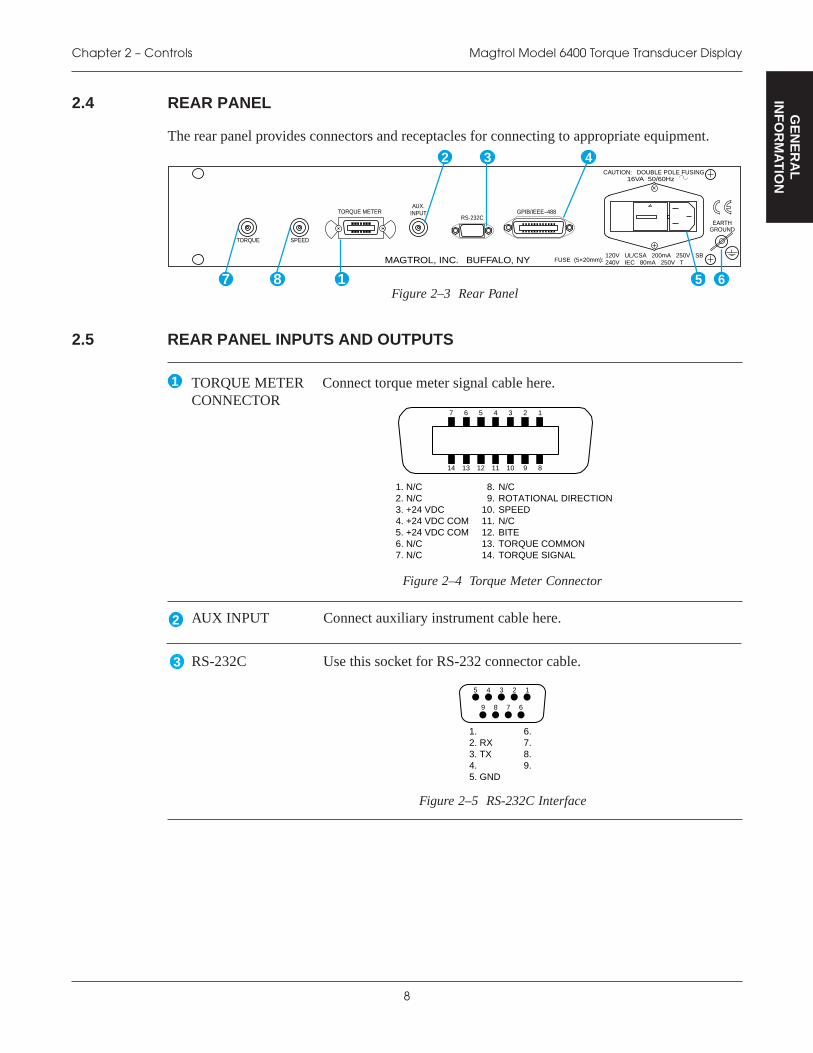
Connect torque meter signal cable here.
14.13.12.11.10.9.8.
TORQUE SIGNALTORQUE COMMONBITEN/CSPEEDROTATIONAL DIRECTIONN/C
7. N/C 6. N/C 5. +24 VDC COM 4. +24 VDC COM 3. +24 VDC 2. N/C 1. N/C
14 3 2
891011
6 5
1213
7
14
Figure 2–4 Torque Meter Connector
2.4 REAR PANEL
The rear panel provides connectors and receptacles for connecting to appropriate equipment.
RS-232CGPIB/IEEE–488
CAUTION: DOUBLE POLE FUSING16VA 50/60Hz
EARTHGROUND
FUSE (5×20mm):120V UL/CSA 200mA 250V SB240V IEC 80mA 250V TMAGTROL, INC. BUFFALO, NY
TORQUE METERAUX.
INPUT
SPEEDTORQUE
Figure 2–3 Rear Panel
2.5 REAR PANEL INPUTS AND OUTPUTS
Use this socket for RS-232 connector cable.
5. GND
1. 6.
9. 3. TX 8. 2. RX
4.
7.
14 3 25
69 8 7
Figure 2–5 RS-232C Interface
AUX INPUT Connect auxiliary instrument cable here.
1
2 3
5 6
4
1
2
TORQUE METERCONNECTOR
RS-232C3
7 8

9
Magtrol Model 6400 Torque Transducer Display Chapter 2 – Controls
GE
NE
RA
LIN
FO
RM
AT
ION
Use this socket for GPIB cable (meets IEEE-488 specifications).
24. SIGNAL GROUND23. ATN-COM22. SRQ-COM21. IFC-COM20. NDAC-COM19. NRFD-COM18. DAV-COM17. REN16. D815. D714. D613. D5
12. SHIELD11. ATN10. SRQ 9. IFC 8. NDAC 7. NRFD 6. DAV 5. E01 4. D4 3. D3 2. D2 1. D1
14 3 2
13141516
6 5
1718
7
19
811 10 9
20212223
12
24
Figure 2–6 GPIB/IEEE-488 Interface
4 GPIB/IEEE-488
Attach power cord here.
Attach earth ground here.EARTHGROUND
6
POWER5
Connect to data acquisition system here.TORQUEOUTPUT
7
Connect to data acquisition system here.SPEEDOUTPUT
8

10
SE
TU
P
3. Installation/Configuration
Note: Before installing the 6400, you should become familiar with thefront and rear panels, as outlined in Chapter 2–Controls.
3.1 POWERING UP THE 6400
WARNING! TO REDUCE THE RISK OF ELECTRIC SHOCK, MAKESURE THE 6400 IS EARTH GROUNDED BEFORESTARTING!
3.1.1 SETTING UNIT FOR LINE VOLTAGE
The 6400 will operate with either of the following power sources:
• 120 V 50/60 Hz
• 240 V 50/60 Hz
1. Find the line cord receptacle on the rear panel. The line cord is a detachable NEMA Standard3-wire.
2. If changing the line voltage:
1) Locate the power entry module.
2) Remove the line cord.
3) Insert a screwdriver into the slot and open the fuse door.
4) Install the appropriate fuses for that voltage as marked on the rear panel of the unit.
3.1.2 SELF-TEST
Note: To make sure that the 6400 is operational, a Magtrol torque sensormust be installed and connected to the 6400. It is not required thatthe 6400 be connected to a computer.
1. Connect the 6400 to the torque transducer using a 14-pin to 6-pin signal cable.
STOPSTOP

11
Magtrol Model 6400 Torque Transducer Display Chapter 3 – Installation/Configuration
SE
TU
P
Figure 3–1 Cable and Connection Diagrams
2. Turn on the power to the 6400. The display panel will show all segments of the VFD (seriesof rectangles), indicating that the 6400 is downloading the program.
POWER/AUX TORQUE SPEED
Figure 3–2 Program Download Display
Note: If the desired results did not occur, please see Chapter 7 –Troubleshooting.
When the program download is complete, the Title Display will appear.
POWER/AUX TORQUE SPEED
Figure 3–3 Title Display
Then an additional display will appear indicating the version of your Magtrol 6400 Torque TransducerDisplay.

12
Magtrol Model 6400 Torque Transducer DisplayChapter 3 – Installation/Configuration
SE
TU
P
POWER/AUX TORQUE SPEED
Figure 3–4 Revision Display
3.1.3 MAIN MENU
When the 6400 is completely powered up and ready for use, the Main Menu will appear on thedisplay.
POWER/AUX TORQUE SPEED
Figure 3–5 Main Menu

13
OP
ER
AT
ION
4. Manually Controlled Operation
Note: Using the 6400 without a personal computer will limit its testingcapabilities.
4.1 SETTING DESIRED OPERATING PARAMETERS
Note: See Appendix B: Front Panel/Display Menu Flow Charts.
4.1.1 POWER UNITS SETUP
Selects the desired unit of power (watts, hp, kW) that corresponds with the values displayed, orselects the auxiliary input (AUX) to be displayed.
1. Press and release SHIFT.
2. Press and release POWER UNITS button. The display appears as follows:
POWER/AUX TORQUE SPEED
POWER UNITS SELECTION
Figure 4–1 Power Units Setup Menu
3. Use UP and DOWN buttons until the desired unit of power is displayed.
4. Press and release SHIFT to make selection and return to main menu.
4.1.2 TORQUE UNITS SETUP
Selects the desired unit of measure (oz·in, oz·ft, lb·in, lb·ft, g·cm, kg·cm, Nmm, Ncm, Nm or kNm)that corresponds with the values displayed.
1. Press and release SHIFT.2. Press and release TORQUE UNITS button. The display appears as follows:
POWER/AUX TORQUE SPEED
TORQUE UNITS SELECTION
Figure 4–2 Torque Units Setup Menu
3. Use UP and DOWN buttons until the desired unit of measure is displayed.
4. Press and release SHIFT to make selection and return to main menu.

14
Magtrol Model 6400 Torque Transducer DisplayChapter 4 – Manually Controlled Operation
OP
ER
AT
ION
4.1.3 SYSTEM PARAMETER SETUP
Includes torque transducer selection, max power setup, direction input setup, as well as encoder andtorque scale factor setup. The following steps will provide instructions for both a standard andcustom torque transducer setup.
4.1.3.1 Standard Torque Transducer Setup
The basic system parameter setup for a standard torque transducer consists of three procedures,which must be performed in the following order:
1. Torque Transducer Selection
2. Max Power Setup
3. Direction Input Setup
Torque Transducer Selection
Selects the torque transducer model in use.
1. Press and release SHIFT.
2. Press and release SETUP button. "MENU: SYSTEM" appears in the display.
3. Press and release SHIFT. The Torque Transducer Selection Menu appears in the display.
4. Use UP and DOWN buttons until the torque transducer model being used appears inthe display.
Max Power Setup
Sets the maximum power set point. Select from a range of 0.1 watts to 100,000 kilowatts.
1. Press and release SHIFT. The display appears as follows:
POWER/AUX TORQUE SPEED
Figure 4–3 Max Power Setup Display
2. Use UP , DOWN , LEFT and RIGHT buttons to select the maximum power setpoint. The maximum power set point is used to indicate an overload condition. If thepower reading exceeds what was programmed, the following message appears in the display:
POWER/AUX TORQUE SPEED
Figure 4–4 Power Overload Display
To clear an overload display, reduce speed and/or torque, then press and hold SHIFT. Theunit will then return to the main menu.
15
Magtrol Model 6400 Torque Transducer Display Chapter 4 – Manually Controlled Operation
OP
ER
AT
ION
Direction Input Setup
When the direction input function is enabled, it tells the 6400 to read the rotational sense bit from thetorque transducer and displays that information in the SPEED portion of the display. A positive (+)reading indicates counterclockwise rotation while a negative (-) reading indicates clockwise rotation.
1. Press and release SHIFT. The display appears as follows:
POWER/AUX TORQUE SPEED
Figure 4–5 Direction Input Setup Menu
2. Use UP and DOWN buttons to turn direction input ON or OFF.
3. Press and release SHIFT to return to main menu.
4.1.3.2 Custom Torque Transducer Setup
The basic system parameter setup for a custom torque transducer consists of five procedures, whichmust be performed in the following order:
1. Torque Transducer Selection
2. Encoder Setup
3. Torque Scale Factor Setup4. Max Power Setup
5. Direction Input Setup
Torque Transducer Selection
Selects the torque transducer model in use.
1. Press and release SHIFT.
2. Press and release SETUP button. "MENU: SYSTEM" appears in the display.
3. Press and release SHIFT. The Torque Transducer Selection Menu appears in the display.
4. Use UP and DOWN buttons until "TM SPECIAL" appears in the display.
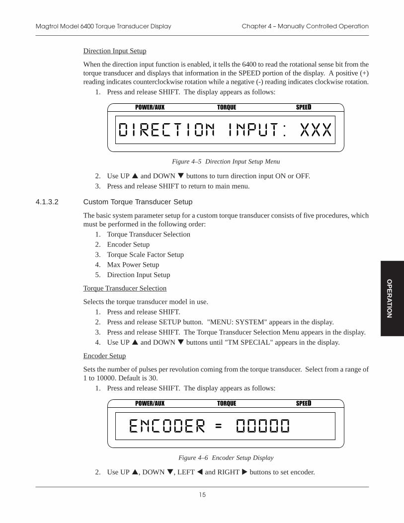
Encoder Setup
Sets the number of pulses per revolution coming from the torque transducer. Select from a range of1 to 10000. Default is 30.
1. Press and release SHIFT. The display appears as follows:
POWER/AUX TORQUE SPEED
Figure 4–6 Encoder Setup Display
2. Use UP , DOWN , LEFT and RIGHT buttons to set encoder.
16
Magtrol Model 6400 Torque Transducer DisplayChapter 4 – Manually Controlled Operation
OP
ER
AT
ION
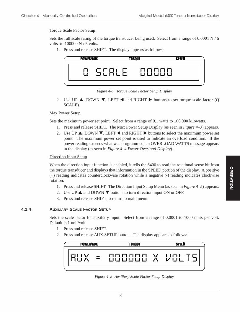
Torque Scale Factor Setup
Sets the full scale rating of the torque transducer being used. Select from a range of 0.0001 N / 5volts to 100000 N / 5 volts.
1. Press and release SHIFT. The display appears as follows:
POWER/AUX TORQUE SPEED
Figure 4–7 Torque Scale Factor Setup Display
2. Use UP , DOWN , LEFT and RIGHT buttons to set torque scale factor (QSCALE).
Max Power Setup
Sets the maximum power set point. Select from a range of 0.1 watts to 100,000 kilowatts.
1. Press and release SHIFT. The Max Power Setup Display (as seen in Figure 4–3) appears.
2. Use UP , DOWN , LEFT and RIGHT buttons to select the maximum power setpoint. The maximum power set point is used to indicate an overload condition. If thepower reading exceeds what was programmed, an OVERLOAD WATTS message appearsin the display (as seen in Figure 4–4 Power Overload Display).
Direction Input Setup
When the direction input function is enabled, it tells the 6400 to read the rotational sense bit fromthe torque transducer and displays that information in the SPEED portion of the display. A positive(+) reading indicates counterclockwise rotation while a negative (-) reading indicates clockwiserotation.
1. Press and release SHIFT. The Direction Input Setup Menu (as seen in Figure 4–5) appears.2. Use UP and DOWN buttons to turn direction input ON or OFF.
3. Press and release SHIFT to return to main menu.
4.1.4 AUXILIARY SCALE FACTOR SETUP
Sets the scale factor for auxiliary input. Select from a range of 0.0001 to 1000 units per volt.Default is 1 unit/volt.
1. Press and release SHIFT.
2. Press and release AUX SETUP button. The display appears as follows:
POWER/AUX TORQUE SPEED
Figure 4–8 Auxiliary Scale Factor Setup Display

17
Magtrol Model 6400 Torque Transducer Display Chapter 4 – Manually Controlled Operation
OP
ER
AT
ION
3. Use UP , DOWN , LEFT and RIGHT buttons to select value.
4. Press and release SHIFT to exit and return to main menu.
4.1.5 PASS/FAIL PARAMETER SETUP
Allows the user to set displayed pass/fail indication of torque, speed or auxiliary input.
1. Press and release SHIFT.
2. Press and release SETUP. "MENU: SYSTEM" appears in the display.
3. Press and release UP button. "MENU: PASS/FAIL" appears in the display.
4. Press and release SHIFT. The display appears as follows:
POWER/AUX TORQUE SPEED
Figure 4–9 Torque Pass/Fail Setup Menu
5. Use UP and DOWN buttons to turn torque pass/fail testing ON or OFF.6. If ON was selected, press and release SHIFT. The display appears as follows:
POWER/AUX TORQUE SPEED
Figure 4–10 High Limit Setup Display
If OFF was selected, go to step 10.
7. Use UP , DOWN , LEFT and RIGHT buttons to select the high limit for torque.Select from a range of 0.0001 to 99999 displayed units.
8. Press and release SHIFT. The display appears as follows:
POWER/AUX TORQUE SPEED
Figure 4–11 Low Limit Setup Display
9. Use UP , DOWN , LEFT and RIGHT buttons to select the low limit for torque.Select from a range of 0.0001 to 99999 displayed units.

18
Magtrol Model 6400 Torque Transducer DisplayChapter 4 – Manually Controlled Operation
OP
ER
AT
ION
10. Press and release SHIFT. The display appears as follows:
POWER/AUX TORQUE SPEED
Figure 4–12 Speed Pass/Fail Setup Menu
11. Use UP and DOWN buttons to turn speed pass/fail testing ON or OFF.
12. If ON was selected, press and release SHIFT. The High Limit Setup Display (as seen inFigure 4–10) appears.
If OFF was selected, go to step 16.
13. Use UP , DOWN , LEFT and RIGHT buttons to select the high limit for speed.Select from a range of 0.0001 to 99999 rpm.
14. Press and release SHIFT. The Low Limit Setup Display (as seen in Figure 4–11) appears.
15. Use UP , DOWN , LEFT and RIGHT buttons to select the low limit for speed.Select from a range of 0.0001 to 99999 rpm.
16. Press and release SHIFT. The display appears as follows:
POWER/AUX TORQUE SPEED
Figure 4–13 Auxiliary Input Pass/Fail Setup Menu
17. Use UP and DOWN buttons to turn auxiliary input pass/fail testing ON or OFF.
18. If ON was selected, press and release SHIFT. The High Limit Setup Display (as seen inFigure 4–9) appears.
If OFF was selected, go to step 22.
19. Use UP , DOWN , LEFT and RIGHT buttons to select the high limit for auxiliaryinput. Select from a range of -99999 to 99999.
20. Press and release SHIFT. The Low Limit Setup Display (as seen in Figure 4–11) appears.
21. Use UP , DOWN , LEFT and RIGHT buttons to select the low limit for auxiliaryinput. Select from a range of -99999 to 99999.
22. Press and release SHIFT to exit. Any pass/fail functions that were enabled will appear inthe display as PASS or FAIL.
POWER/AUX TORQUE SPEED
Figure 4–14 Pass/Fail Display Example

19
Magtrol Model 6400 Torque Transducer Display Chapter 4 – Manually Controlled Operation
OP
ER
AT
ION
4.1.6 INPUT/OUTPUT (I/O) PARAMETER SETUP
Sets up GPIB (IEEE-488) address, serial (RS-232) baud rate and display contrast.
1. Press and release SHIFT.
2. Press and release SETUP. "MENU: SYSTEM" appears in the display.
3. Press and release UP button twice. "MENU: I/O appears in the display.
4. Press and release SHIFT. The Contrast Setup Menu (as seen in Figure 2–2) appears.
5. Use UP and DOWN buttons until desired contrast level is displayed.
6. Press and release SHIFT. The display appears as follows:
POWER/AUX TORQUE SPEED
Figure 4–15 GPIB Address Setup Menu
7. Use UP and DOWN buttons until desired GPIB address is displayed. Select from arange of 0 to 15.
8. Press and release SHIFT . The display appears as follows:
POWER/AUX TORQUE SPEED
Figure 4–16 RS-232 Baud Rate Setup Menu
9. Use UP and DOWN buttons until desired RS-232 baud rate is displayed. Select from300, 600, 1200, 2400, 4800, 9600 and 19200.
10. Press and release SHIFT to exit and return to main menu.
4.2 USING INTERNAL MEMORY
4.2.1 STORING DATA POINTS
1. Press and release STORE button. The display will indicate STORE followed by a number.
POWER/AUX TORQUE SPEED
Figure 4–17 Store Display
This display indicates the memory location that contains the data.

20
Magtrol Model 6400 Torque Transducer DisplayChapter 4 – Manually Controlled Operation
OP
ER
AT
ION
2. Continue pressing STORE at each desired point.
4.2.2 RECALLING DATA POINTS
1. Press and release RECALL button. The display will indicate RECALL followed by a number.
POWER/AUX TORQUE SPEED
Figure 4–18 Recall Display
This number indicates the memory location that is being displayed. The order of recalleddata is LAST IN = FIRST OUT (LIFO). An "M" also appears to the right of the SPEEDdisplay to let the user know that the displayed data is from memory and not real time data.
POWER/AUX TORQUE SPEED
Figure 4–19 Main Menu with Recall Function Enabled
2. Use UP and DOWN buttons until desired data is retrieved.
4.2.3 EXITING THE MEMORY MODE
1. Press and release SHIFT.
4.2.4 CLEARING THE MEMORY
1. Press and release SHIFT.
2. Press and release CLEAR MEM button. "CLEAR MEMORY" will flash in the display andthen return automatically to the main menu.
4.3. USING THE TARE FUNCTION
The calibrated offset of the 6400 may be changed using the tare function.
To set:
1. Press TARE.
2. Screen will flash "TARE SET" and the unit will take the current value of the inputs andmake them the new zero.
Note: In order to reset the tare value, the power to the unit must be turnedOFF.
21
Magtrol Model 6400 Torque Transducer Display Chapter 4 – Manually Controlled Operation
OP
ER
AT
ION
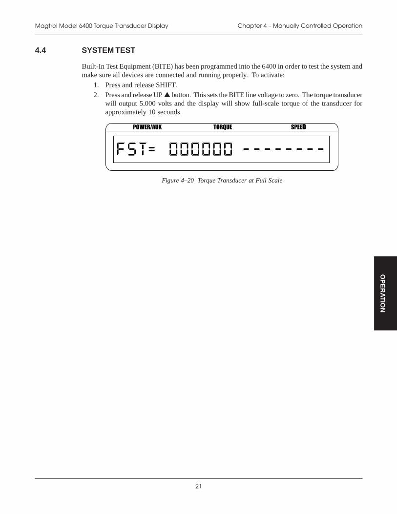
4.4 SYSTEM TEST
Built-In Test Equipment (BITE) has been programmed into the 6400 in order to test the system andmake sure all devices are connected and running properly. To activate:
1. Press and release SHIFT.
2. Press and release UP button. This sets the BITE line voltage to zero. The torque transducerwill output 5.000 volts and the display will show full-scale torque of the transducer forapproximately 10 seconds.
POWER/AUX TORQUE SPEED
Figure 4–20 Torque Transducer at Full Scale

22
OP
ER
AT
ION
5. Computer Controlled Operation
The 6400 can be used with a personal computer (PC) to acquire and log data. Using the 6400 witha computer enables the unit to perform at its full capacity.
5.1 ABOUT THE GPIB INTERFACE
Magtrol prefers the GPIB (General Purpose Interface Bus)/IEEE-488 Standard for computer-to-instrument interfacing because:
• The GPIB parallel interface is faster than serial interfaces.
• The GPIB enables testers to access up to 15 instruments on one port. Because typical motortesting requires that at least five separate parameters be synchronized, a system of easy, fastaccess to more than one instrument is essential.
• The GPIB has rigid data formatting and hardware standards. These standards help to ensurethat all functions will work properly when the hardware and software are installed.
Note: The GPIB interface is not standard on most computers. An interfacecard and driver software must be installed. An IEEE-488 cable mustalso be installed between the computer and the 6400. Magtrolrecommends National Instruments Corporation hardware and software.
5.1.1 CONNECTING THE GPIB (IEEE-488) CABLE
CAUTION: MAKE SURE BOTH THE COMPUTER AND 6400 ARE TURNED OFF BEFORE
INSTALLING THE GPIB CONNECTOR CABLE.
1. Connect one end of a high-quality, double-shielded cable to the 6400 GPIB connector.
2. Connect the other end to the GPIB interface in your personal computer.
PC
TM SOFTWARE
RS-232CGPIB/IEEE–488
CAUTION: DOUBLE POLE FUSING16VA 50/60Hz
EARTHGROUND
FUSE (5×20mm):120V UL/CSA 200mA 250V SB240V IEC 80mA 250V TMAGTROL, INC. BUFFALO, NY
TORQUE METERAUX.
INPUT
Figure 5–1 GPIB Installation
23
Magtrol Model 6400 Torque Transducer Display Chapter 5 – Computer Controlled Operation
OP
ER
AT
ION
5.1.2 CHANGING THE GPIB PRIMARY ADDRESS
Each instrument serviced by the GPIB has its own primary address code, which enables the computerto obtain readings from the instrument. The factory default of the setting on the 6400 is 11.
Some personal computer interfaces can access from one to fifteen 4-bit primary addresses. Otherinterfaces can access as many as thirty-one 5-bit primary addresses. The 6400 uses the 4-bit format.For setup, follow the steps below.
1. Press and release SHIFT.
2. Press and release SETUP . "MENU: SYSTEM" appears in the display.
3. Press and release UP button twice. "MENU: I/O" appears in the display.
4. Press and release SHIFT twice. The GPIB Address Setup Menu (as seen in Figure 4–15)appears in the display.
5. Use UP and DOWN buttons until desired primary address is reached (range: 0 to 15).
6. Press and release SHIFT twice to return to main menu
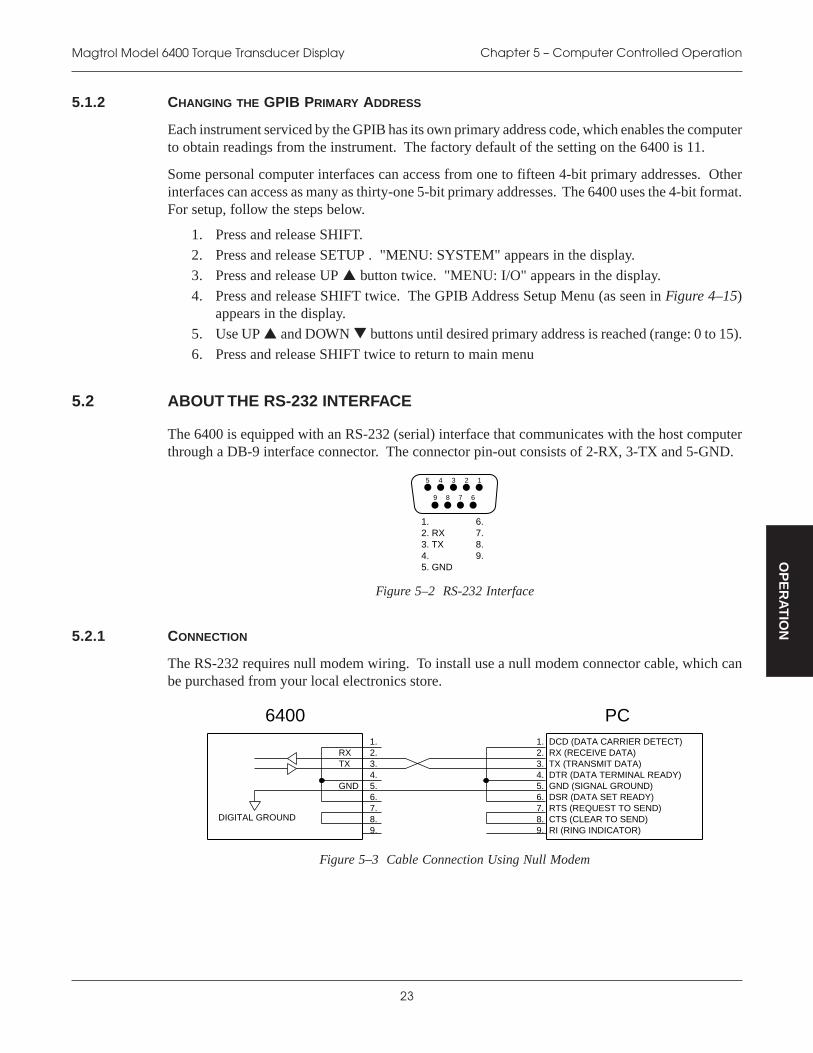
5.2 ABOUT THE RS-232 INTERFACE
The 6400 is equipped with an RS-232 (serial) interface that communicates with the host computerthrough a DB-9 interface connector. The connector pin-out consists of 2-RX, 3-TX and 5-GND.
5. GND
1. 6.
9. 3. TX 8. 2. RX
4.
7.
14 3 25
69 8 7
Figure 5–2 RS-232 Interface
5.2.1 CONNECTION
The RS-232 requires null modem wiring. To install use a null modem connector cable, which canbe purchased from your local electronics store.
DIGITAL GROUND
4.
2. 3.
6.
1.
5.
7. 8. 9.
6400 PC
5. GND (SIGNAL GROUND)
1. DCD (DATA CARRIER DETECT)
6. DSR (DATA SET READY)
3. TX (TRANSMIT DATA) 2. RX (RECEIVE DATA)
4. DTR (DATA TERMINAL READY)
9. RI (RING INDICATOR) 8. CTS (CLEAR TO SEND) 7. RTS (REQUEST TO SEND)
RXTX
GND
Figure 5–3 Cable Connection Using Null Modem

24
Magtrol Model 6400 Torque Transducer DisplayChapter 5 – Computer Controlled Operation
OP
ER
AT
ION
Note: If the desired results did not occur, please see Chapter 7 –Troubleshooting.
Desired Results
• Torque/speed data will be returned.
• The string does not return with a COMMAND ERROR CR-LF message.
5.2.2 COMMUNICATION PARAMETERS
• No parity
• 8 data bits
• 1 stop bit
5.2.3 BAUD RATE
There are several different baud rates to choose from including 300, 600, 1200, 2400, 4800, 9600and 19200. To set up the desired baud rate, follow the instructions below.
1. Press and release SHIFT.
2. Press and release SETUP. "MENU: SYSTEM" appears in the display.
3. Press and release UP button twice. "MENU: I/O" appears in the display.
4. Press SHIFT three times. The RS-232 Baud Rate Setup Menu (as seen in Figure 4–16)appears in the display.
5. Use the UP and DOWN buttons until desired baud rate is reached.
6. Press and release SHIFT to make selection and return to main menu.
5.3 CHECKING THE 6400-TO-PC CONNECTION
Note: The 6400 and its host computer must be communicating beforeacquiring data.
1. Make sure the primary GPIB address is set correctly for the 6400.
2. Set the input variable to 16 characters (14 variable characters and the two required datatermination characters CR and LF. See Section 5.5 – Programming.)
3. Issue output data command "OD" and read 15 characters according to the instructions foryour GPIB interface or serial.

25
Magtrol Model 6400 Torque Transducer Display Chapter 5 – Computer Controlled Operation
OP
ER
AT
ION
5.4 DATA FORMAT
Speed-torque data is a fixed-length string in ASCII format with a floating point decimal. Use thefollowing string format:
SdddddTdddd.RX<cr><lf>
Or
SdddddTdddd.LX<cr><lf>
Where…
S = Speed in rpm. (No leading zeros are used.)
d = Decimal digit 0 through 9.
T = Torque in units selected during setup. (The torque value always contains a decimal point.)
L = Counterclockwise dynamometer shaft rotation (left).
R = Clockwise dynamometer shaft rotation (right).
X = If the direction input is ON (enabled under system setup), a 0 will indicate counterclockwiserotation and a 1 will indicate clockwise rotation. If direction input is OFF, this characteris undefined.
. = Decimal point. (The decimal point location depends on the specific torque transducerand torque range in use.)
Note: The [cr] and [lf] characters will not display.
EXAMPLE
If a motor is running at 1725 rpm clockwise, with the torque transducer loading the motorto 22.6 oz·in, the 6400 will return:
S 1725T22.60L1
By manipulating the string, the speed-torque and shaft direction (if required) can be extracted.Then separate numerical variables can be assigned to them for data processing.

26
Magtrol Model 6400 Torque Transducer DisplayChapter 5 – Computer Controlled Operation
OP
ER
AT
ION
5.5 PROGRAMMING
Note: Check the manual provided with your software for full instructions.
5.5.1 DATA TERMINATION CHARACTERS
Use the following information to answer the formatting questions asked when installingyour GPIB software. All GPIB data acquisition systems require the use of data terminationcharacters. The 6400 uses the GPIB standard termination characters Carriage Return (CR)and Line Feed (LF). Provide them in that order.
5.5.1.1 Codes for CR - LF
CISAB XEH CED
=RC )31($RHC D0 31
=FL )01($RHC A0 01
5.4.2 TIMEOUT
Set the timeout for at least one second if asked to set a communication fault delay timeout.
Note: If the communication fault delay timeout is too short, or if thecomputer resets the interface too quickly, the host instrument maystop responding.

27
Magtrol Model 6400 Torque Transducer Display Chapter 5 – Computer Controlled Operation
OP
ER
AT
ION
5.6 6400 COMMAND SET
When entering a command code:
1. Type all characters in uppercase ASCII format.
2. End all commands with a CR-LF (hex 0D-0A).
3. Do not string multiple commands together in one line.
The character # represents a floating-point numerical value following the command. Leading zeroesare not required.
Note: If a command is not recognized, a COMMAND ERROR CR-LFstring return will occur accompanied by a beep.
5.6.1 COMMUNICATION COMMANDS
dnammoCedoC noitcnuF noitanalpxE
?NDI .edomeriuqnI "xx.xVER0046LORTGAM"=esnopseRyreuq2.884-EEEI
H etarnoitisiuqcaatadhgihsteS.)dnocesrepselpmas001(
001taatadstuptuoyalpsiDrecudsnarTeuqroTehT).s/S06sietareht,ecafretni232-SRnagnisU(s/S
L etarnoitisiuqcaatadwolsteS.)dnocesrepselpmas8.3(
8.3taatadstuptuoyalpsiDrecudsnarTeuqroTehT.)etartluafed(s/S
AO yrailixuaotnruterotstpmorP.gnirtsatadtupni
ehttaeulavehtnruterottpmorp"yrailixuAtuptuO".rotcafGNILACSXUA×TUPNIXUA
DO -deepsnruterotstpmorP.gnirtsatadnoitcerid-euqrot
sihthtiwgnirtsatadnruterottpmorp"ataDtuptuO":tamrof
XRxxxxxTxxxxxS fl<>rc< > roXLxxxxxTxxxxxS >fl<>rc<
:erehw,rotacidninoitceridtfahsehtsiLroR)WC(esiwkcolc;tfel=L
)WCC(esiwkcolcretnuoc;thgir=RehtdnaeulavdeyalpsidehtlauqelliwdeepsehT
nodeyalpsidsastinuemasehtnieblliweuqrot.lenaptnorfeht

28
Magtrol Model 6400 Torque Transducer DisplayChapter 5 – Computer Controlled Operation
OP
ER
AT
ION
dnammoCedoC noitcnuF noitanalpxE
RD .noitceridsteseR .noitacidni±sedivorplangiseuqroT
SD .noitceridsteS ±etacidniotrecudsnartmorftibnoitceridesU.)mpr02evoba(euqrot
1M .slortnoclenaptnorfselbanE folortnoclenaptnorfelbaneotdnammocsihtesU.snoitcnuftsom
ØM .slortnoclenaptnorftuoskcoL lenaptnorfehttuokcolotdnammocsihtesUyalpsiDrecudsnarTeuqroTehttahtos,slortnoc
ehtgnisuybylnodegnahcebnacsgnittesehtro)884-EEEI(BIPGehtrehtiehtiwretupmoc
.ecafretni232-SR
R :swollofsasteseRNOlortnoclaunaM•
etarnoitisiuqcaatadwoL•FFOeraT•
suoiverpynalecnacotdnammocsihtesU.sdnammoc
:etoN tluafedno-rewopehterasgnittesesehT.sgnittes
RT .eraTsteseR .)orez(0oteratsteseR
ST .eraTsteS .eulaveratsasesudnaeuqrottnerrucsdaeR
#AU .#otgnilacstupniyrailixuasteS ehtrofrotcafgnilacsehtstesdnammocsihTot0siegnarehT.tlov/stinu#ottupniyrailixua
rewoptadevastonsi#eulavdemmargorP.00001.nwod
#EU nehw#otstinuredocnesteS.dnammoc41IUagnisu
0001ot0=#
#IU .ledomstceleS eht,tcerrocebotsnoitaluclacsttawdnaphroF.deificepsebtsumrecudsnarteuqrottcerroc
:etoN euqroTseireSMTehtfoynasedulcni"MT")BMTroSHMT,MT(srecudsnarT
:era#rofseulaVmN002,212MT=8mN1,402MT=0mN005,312MT=9mN2,502MT=1
mN0001,412MT=01mN5,602MT=2mN0002,512MT=11mN01,702MT=3mN0005,612MT=21mN02,802MT=4mN00001,712MT=31mN02,902MT=5
LAICEPSMT=41mN05,012MT=6mN001,112MT=7
.nwodrewoptadevastonsi#eulavdemmargorP
#RU .#otstinueuqrotyalpsidsteS :era#rofseulaVmc·gk=5ni·zo=0
mmN=6tf·zo=1mcN=7ni·bl=2
mN=8tf·bl=3mNk=9mc·g=4
fotuofi)ni·zo(0otstluafednoisrevnoctinueuqroTrewoptadevastonsi#eulavdemmargorP.egnar
.nwod
#TU nehw#otstinueuqrotsteS.dnammoc41IUagnisu
000,001ot0=#
5.6.2 SETUP COMMANDS

29
Magtrol Model 6400 Torque Transducer Display Chapter 5 – Computer Controlled Operation
OP
ER
AT
ION
dnammoCedoC noitcnuF noitanalpxE
TZC .orezeuqrotsteS eeS noitarbilaC-6retpahC .
AZC .orez.xuasteS eeS noitarbilaC-6retpahC .
TFC .niageuqrotsteS eeS noitarbilaC-6retpahC .
AFC .niag.xuasteS eeS noitarbilaC-6retpahC .
5.6.3 CALIBRATION COMMANDS

30
MA
INT
EN
AN
CE
6. Calibration
6.1 CLOSED-BOX CALIBRATION
The 6400 features closed-box calibration. The advantage of closed-box calibration is that the userdoes not have to disassemble the case or make mechanical adjustments.
The torque readout and auxiliary input can be calibrated using external reference sources. Correctionfactors for offset and gain are stored in nonvolatile memory. They remain in effect until the user orthe calibration house updates them.
The front panel displays the actual values for the ZERO and GAIN correction factors. Record thesevalues before calibration. In the unlikely event of a Torque Transducer Display failure, it can be re-initialized by pressing and holding the STORE and RECALL buttons while turning the power on.All internal memory and setups will be lost. After re-initializing, reprogram the GAIN and ZEROvalues into memory.
6.2 CALIBRATION SCHEDULE
Calibrate the 6400:
• After any repairs are performed.
• At least once a year; more frequently to ensure required accuracy.
6.3 BASIC CALIBRATION PROCESS
The basic calibration process consists of four procedures which must be performed in the followingorder:
1. Initial Procedure
2. Torque Offset and Gain (computer or manual)
3. Auxiliary Input Offset and Gain (computer or manual)
Items needed for calibrating the 6400:
• External voltage reference of 0 to 10 volts DC
• Digital multimeter (DMM)
Both instruments should have a VDC accuracy of 0.05% or better.
6.3.1 INITIAL CALIBRATION PROCEDURE
1. Allow the 6400 to stabilize in an environment with:
• An ambient temperature of 18°C to 25°C.• Relative humidity less than 80%.
2. Turn on the 6400.
3. Allow the 6400 to warm up for at least 30 minutes.
4. Go to computer or manual calibration sections.
31
Magtrol Model 6400 Torque Transducer Display Chapter 6 – Calibration
MA
INT
EN
AN
CE
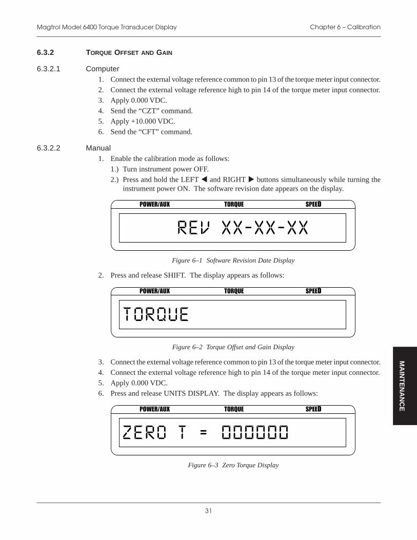
6.3.2 TORQUE OFFSET AND GAIN
6.3.2.1 Computer1. Connect the external voltage reference common to pin 13 of the torque meter input connector.
2. Connect the external voltage reference high to pin 14 of the torque meter input connector.
3. Apply 0.000 VDC.
4. Send the “CZT” command.
5. Apply +10.000 VDC.
6. Send the “CFT” command.
6.3.2.2 Manual1. Enable the calibration mode as follows:
1.) Turn instrument power OFF.
2.) Press and hold the LEFT and RIGHT buttons simultaneously while turning theinstrument power ON. The software revision date appears on the display.
POWER/AUX TORQUE SPEED
Figure 6–1 Software Revision Date Display
2. Press and release SHIFT. The display appears as follows:
POWER/AUX TORQUE SPEED
Figure 6–2 Torque Offset and Gain Display
3. Connect the external voltage reference common to pin 13 of the torque meter input connector.
4. Connect the external voltage reference high to pin 14 of the torque meter input connector.
5. Apply 0.000 VDC.6. Press and release UNITS DISPLAY. The display appears as follows:
POWER/AUX TORQUE SPEED
Figure 6–3 Zero Torque Display

32
Magtrol Model 6400 Torque Transducer DisplayChapter 6 – Calibration
MA
INT
EN
AN
CE
7. Press and release SHIFT. The display appears as follows:
POWER/AUX TORQUE SPEED
Figure 6–4 Full Scale Torque Display 1
8. Apply +10.000 VDC. The display appears as follows:
POWER/AUX TORQUE SPEED
Figure 6–5 Full Scale Torque Display 2
9. Press and release SHIFT twice to exit calibration and return to main menu.
Note: To exit calibration mode without making any changes, press theSHIFT button twice.
6.3.3 AUXILIARY INPUT OFFSET AND GAIN
6.3.3.1 Computer1. Connect the external voltage reference to the Auxiliary Input BNC connector.
2. Apply 0.000 VDC.
3. Send the CZA command.
4. Apply +10.000 VDC.
5. Send the CFA command.
6.3.3.2 Manual1. Enable the calibration mode as follows:
1.) Turn instrument power OFF.
2.) Press and hold the LEFT and RIGHT buttons simultaneously while turning theinstrument power ON. The software revision date appears on the display as shown inFigure 6–1.

33
Magtrol Model 6400 Torque Transducer Display Chapter 6 – Calibration
MA
INT
EN
AN
CE
2. Press and release SHIFT twice. The display appears as follows:
POWER/AUX TORQUE SPEED
Figure 6–6 Auxiliary Offset and Gain Display
3. Connect the external voltage reference to the Auxiliary Input BNC connector.
4. Apply 0.000 VDC.
5. Press and release UNITS DISPLAY. The display appears as follows:
POWER/AUX TORQUE SPEED
Figure 6–7 Zero Auxiliary Display
6. Press and release SHIFT. The display appears as follows:
POWER/AUX TORQUE SPEED
Figure 6–8 Full Scale Auxiliary Display 1
7. Apply +10.000 VDC. The display appears as follows:
POWER/AUX TORQUE SPEED
Figure 6–9 Full Scale Auxiliary Display 2
8. Press and release SHIFT to exit calibration and return to the main menu.

34
MA
INT
EN
AN
CE
7. Troubleshooting
If you require additional assistance, please contact Magtrol Customer Service at 1-716-668-5555.
melborP nosaeR noituloS
setacidniataddenruteR.RORREDNAMMOC
ehthctamtonseoddnammoCfotesdemmargorps'tinu
.snoitcurtsni
dnadnammoctcerrocesU.tamrof
hcumsdaerrewoplacinahceM.detcepxenahtrewolrorehgih
sirotcafelacsrostinueuqroT.tcerrocni
dnastinutupnieuqrotteSehthctamotrotcafelacs
euqrotfosnoitacificeps.recudsnart
.noitacinummocBIPGoN erawdrahro/dnarorreputeS.tluaf
:kcehCeuqroTfosserddaBIPG•
.yalpsiDrecudsnarTebdluohs:elbacBIPG•
otdehcattadnagninoitcnufdnayalpsiDrecudsnarTeuqroT
dracecafretniretupmoc
.noitacinummoc232-SRoN erawdrahro/dnarorreputeS.tluaf
:kcehCeuqroTfoetarduaB•
yalpsiDrecudsnarTelbaclairesfotuoniP•
euqroTottnemhcattaelbaC•lairesdnayalpsiDrecudsnarT
retupmocfotropecafretni
35
AP
PE
ND
ICE
S
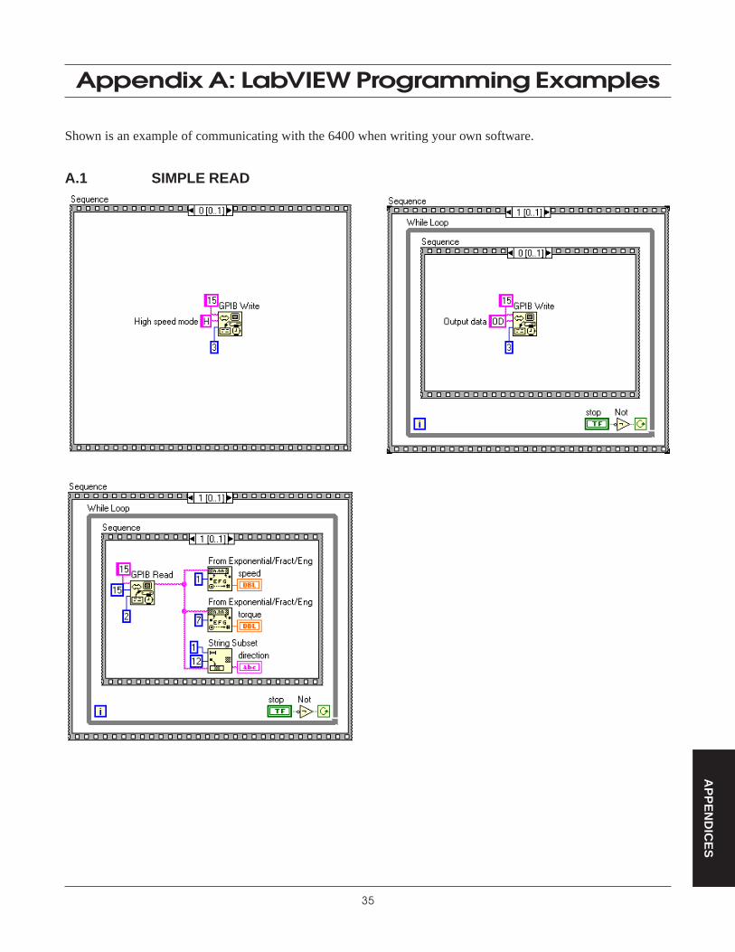
Appendix A: LabVIEW Programming Examples
Shown is an example of communicating with the 6400 when writing your own software.
A.1 SIMPLE READ

36
AP
PE
ND
ICE
S
Appendix B: Front Panel/Display Menu Flow Charts
B.1 SETUP MENU
TM 2041 Nm
TM 2052 Nm
TM 2065 Nm
TM 20710 Nm
TM 20820 Nm
TM 20920 Nm
TM 21050 Nm ON
MODELTM 211100 Nm
MAX POWER(0–99999) DIRECTION
TM 212200 Nm OFF
TM 213500 Nm
TM 2141000 Nm
TM 2152000 Nm
TM 2165000 Nm
SETUPTM 217
10000 Nm
TM SPECIALENCODER(1–10000)
Q SCALE(0.0001–100000)
ONHIGH LIMIT(0–99999)
LOW LIMIT(0–99999) ON
HIGH LIMIT(0–99999)
LOW LIMIT(0–99999) ON
HIGH LIMIT(0–99999)
LOW LIMIT(0–99999)
PASS/FAILTORQUE
P/FSPEED
P/FAUX P/F
OFF OFF OFF
CONTRAST(0–3)
GPIB ADDRS(0–15)
19200
9600
I/O 4800
RS-232BAUD 2400
1200
600
300
EXIT

37
Magtrol Model 6400 Torque Transducer Display Appendix B: Front Panel/Display Menu Flow Charts
AP
PE
ND
ICE
S
B.2 TORQUE UNITS MENU
oz.in.
oz.ft.
lb.in.
lb.ft.
g.cm.
kg.cm.
Nmm
Ncm
Nm
kNm
TORQUEUNITS:

38
Magtrol Model 6400 Torque Transducer DisplayAppendix B: Front Panel/Display Menu Flow Charts
AP
PE
ND
ICE
S
B.3 AUX SETUP MENU
B.4 POWER UNITS MENU
AUX SETUP: SCALE:0 - 10000
UNITS/VOLT
W
AUX
hp
kW
POWER UNITS:

39
AP
PE
ND
ICE
S
Appendix C: Schematics
C.1 ANALOG SECTION

40
Magtrol Model 6400 Torque Transducer DisplayAppendix C: Schematics
AP
PE
ND
ICE
S
C.2 CPU SECTION
41
Magtrol Model 6400 Torque Transducer Display Appendix C: Schematics
AP
PE
ND
ICE
S
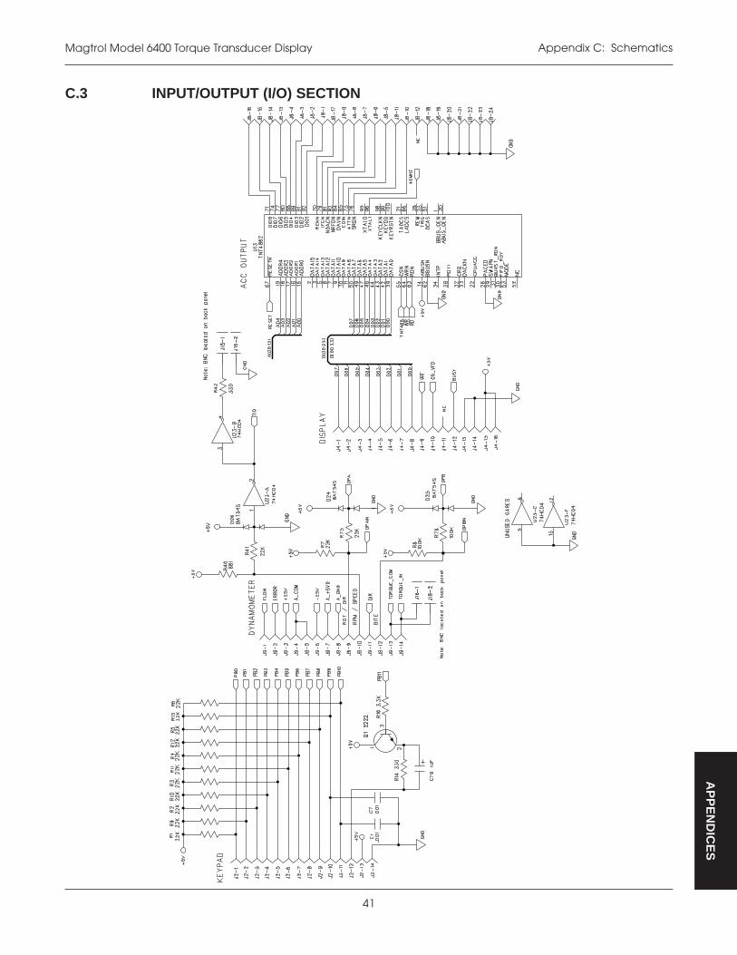
C.3 INPUT/OUTPUT (I/O) SECTION

42
Magtrol Model 6400 Torque Transducer DisplayAppendix C: Schematics
AP
PE
ND
ICE
S
C.4 POWER SUPPLY SECTION

43
Magtrol Model 6400 Torque Transducer Display Appendix C: Schematics
AP
PE
ND
ICE
S
C.5 KEYPADS
W1
SW
2
SW
3
SW
5
SW
6
SW
8
SW
7
SW
9
SW
10
SW
11
2 3
1 4
2 3
1 4
2 3
1 4
2 3
1 4
2 3
1 4
2 3
1 4
2 3
1 4
2 3
1 4
2 3
1 4
2 3
1 4
MT
1
MT
2
MT
3
MT
4
MT
5
MT
6
MT
7
MT
8
SP
KR
1
J1–1
0
J1–9
J1–8
J1–7
J1–6
J1–5
J1–4
J1–3
J1–2
J1–1
J1–1
1
J1–1
2
J1–1
3
J1–1
4
44
Index
AAnalog Section 39AUX Input 8. See also Auxiliary InputAUX Setup Menu 38Auxiliary Input Offset and Gain 32Auxiliary Input Pass/Fail Setup Menu 18Auxiliary Scale Factor Setup 16
BBaud Rate 19, 24BITE. See Built-In Test SystemBuilt-In Test Equipment 21Buttons 5–6
CCalibration 30
Procedure 30–33Schedule 30
Calibration Commands 29Carriage Return (CR). See Data Termination CharactersClosed-Box Calibration 30Command Set 27Commands
Calibration 29Communication 27Setup 28
Communication Commands 27Communication Parameters 24Connection 11
GPIB 22RS-232 23
Contrast 7Controls and Buttons 5–6CPU Section 40
DData Format 25Data Points. See also Memory
Recalling 20Storing 19
Data Sheet 3Data Termination Characters 26Direction Input Setup 15, 16Direction Input Setup Menu 15
EEncoder Setup 15
FFeatures 1Front Panel 5
Functions. See also Controls and ButtonsSecondary 5
GGain
Auxiliary Input 32Torque 31
General Purpose Interface Bus. See GPIBGPIB
Address 19Connection 22Interface 9, 22–23Primary Address 23
GPIB Address Setup Menu 19GPIB/IEEE-488. See GPIB
IIEEE-488. See GPIBInput/Output (I/O) Parameter Setup 19Input/Output (I/O) Section 41Inputs 8
Auxiliary 8Internal Memory. See Memory
KKeypad 43
LLabVIEW Programming Examples 35Line Feed (LF). See Data Termination CharactersLine Voltage 10
MMain Menu 12Max Power Setup 14, 16Memory 19–20. See also Data Points
Clearing 20Exiting 20Recalling 20Storing 19
MenusAUX Setup 38Auxiliary Input Pass/Fail Setup 18Direction Input Setup 15GPIB Address Setup 19Main 12Power Units 38Power Units Setup 13RS-232 Baud Rate Setup 19Setup 36Speed Pass/Fail Setup 18

45
Magtrol Model 6400 Torque Transducer Display Index
Torque Pass/Fail Setup 17Torque Units 37Torque Units Setup 13
OOffset
Auxiliary Input 32Torque 31
Outputs 8. See also Inputs
PParameters 13–19Pass/Fail Parameter Setup 17PC Connection 24Power Overload 14Power Supply Section 42Power Units Menu 38Power Units Setup 13Power Units Setup Menu 13Programming 26
RRear Panel 8Recalling Data Points 20RS-232
Connection 23RS-232 Baud Rate Setup Menu 19RS-232 Interface 23RS-232C 8
SSchematics
Analog Section 39CPU Section 40Input/Output (I/O) Section 41Keypad 43Power Supply Section 42
Secondary Functions 5Self-Test 10Setup
Auxiliary Scale Factor 16Direction Input 15, 16Encoder 15GPIB Address 19Input/Output (I/O) Parameters 19Max Power 14, 16Pass/Fail Parameters 17Power Units 13RS-232 Baud Rate 19System Parameter 14Torque Scale Factor 16Torque Transducer - Custom 15–16Torque Transducer - Standard 14–15Torque Units 13
Setup Commands 28Setup Menu 36Simple Read 35Speed Pass/Fail Setup Menu 18Storing Data Points 19System Parameter Setup 14System Test 21
TTare Function 20Timeout 26Torque Meter Connector 8Torque Offset and Gain 31Torque Pass/Fail Setup Menu 17Torque Scale Factor Setup 16Torque Transducer Selection 14, 15Torque Transducer Setup
Custom 15–16Standard 14–15
Torque Units Menu 37Torque Units Setup 13Torque Units Setup Menu 13Troubleshooting 34
UUnpacking 1
VVacuum Fluorescent Display 7VFD. See Vacuum Fluorescent Display

Magtrol, Inc. warrants its products to be free from defects in material and workmanship under normal use andservice for a period of 24 months from the date of shipment. Software is warranted to operate in accordance withits programmed instructions on appropriate Magtrol instruments. This warranty extends only to the original purchaserand shall not apply to fuses, computer media, or any other product which, in Magtrol’s sole opinion, has beensubject to misuse, alteration, abuse or abnormal conditions of operation or shipping.
Magtrol’s obligation under this warranty is limited to repair or replacement of a product which is returned to thefactory within the warranty period and is determined, upon examination by Magtrol, to be defective. If Magtroldetermines that the defect or malfunction has been caused by misuse, alteration, abuse or abnormal conditions ofoperation or shipping, Magtrol will repair the product and bill the purchaser for the reasonable cost of repair. If theproduct is not covered by this warranty, Magtrol will, if requested by purchaser, submit an estimate of the repaircosts before work is started.
To obtain repair service under this warranty, purchaser must forward the product (transportation prepaid) and adescription of the malfunction to the factory. The instrument shall be repaired at the factory and returned topurchaser, transportation prepaid. MAGTROL ASSUMES NO RISK FOR IN-TRANSIT DAMAGE.
THE FOREGOING WARRANTY IS PURCHASER’S SOLE AND EXCLUSIVE REMEDY AND IS IN LIEU OFALL OTHER WARRANTIES, EXPRESSED OR IMPLIED, INCLUDING BUT NOT LIMITED TO ANY IMPLIEDWARRANTY OF MERCHANTABILITY, OR FITNESS FOR ANY PARTICULAR PURPOSE OR USE.MAGTROL SHALL NOT BE LIABLE FOR ANY SPECIAL, INDIRECT, INCIDENTAL, OR CONSEQUENTIALDAMAGES OR LOSS WHETHER IN CONTRACT, TORT, OR OTHERWISE.
CLAIMS
Immediately upon arrival, purchaser shall check the packing container against the enclosed packing list and shall,within thirty (30) days of arrival, give Magtrol notice of shortages or any nonconformity with the terms of the order.If purchaser fails to give notice, the delivery shall be deemed to conform with the terms of the order.
The purchaser assumes all risk of loss or damage to products upon delivery by Magtrol to the carrier. If a productis damaged in transit, PURCHASER MUST FILE ALL CLAIMS FOR DAMAGE WITH THE CARRIER to obtaincompensation. Upon request by purchaser, Magtrol will submit an estimate of the cost to repair shipment damage.
Magtrol Limited Warranty
46

www.magtrol.comTesting, Measurement and Control of Torque-Speed-Power • Load-Force-Weight • Tension • Displacement
MAGTROL INC70 Gardenville ParkwayBuffalo, New York 14224 USAPhone: +1 716 668 5555Fax: +1 716 668 8705E-mail: [email protected]
MAGTROL SARoute de Moncor 4B1701 Fribourg, SwitzerlandPhone: +41 (0)26 407 3000Fax: +41 (0)26 407 3001E-mail: [email protected]
Subsidiaries in:• Germany• France• Great Britain
Worldwide Networkof Sales Agents ISO 9001
CE
R
T IFIC ATI ON
SWISS
Magtrol SA ISO 9001:2000 certified