model 972 harvest header model 742 hay conditioner …€¦ · model 972 harvest header model 742...
TRANSCRIPT

Model 972HARVEST HEADER
Model 742
HAY CONDITIONER
OPERATOR’S MANUAL
Form 46290 Issue 09/05
Sugg. Retail: $15.00

Inside Front Cover (blank)
Form # 46290 Issue 09/05 1
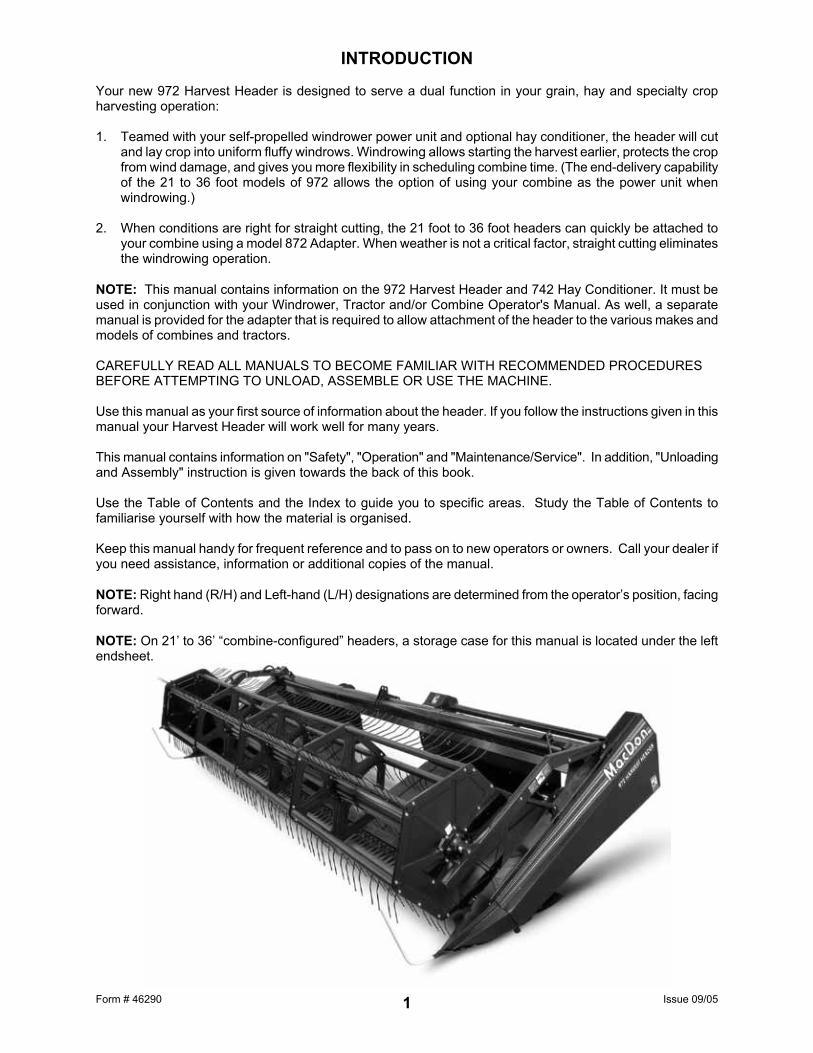
INTRODUCTION Your new 972 Harvest Header is designed to serve a dual function in your grain, hay and specialty crop harvesting operation: 1. Teamed with your self-propelled windrower power unit and optional hay conditioner, the header will cut
and lay crop into uniform fluffy windrows. Windrowing allows starting the harvest earlier, protects the crop from wind damage, and gives you more flexibility in scheduling combine time. (The end-delivery capability of the 21 to 36 foot models of 972 allows the option of using your combine as the power unit when windrowing.)
2. When conditions are right for straight cutting, the 21 foot to 36 foot headers can quickly be attached to
your combine using a model 872 Adapter. When weather is not a critical factor, straight cutting eliminates the windrowing operation.
NOTE: This manual contains information on the 972 Harvest Header and 742 Hay Conditioner. It must be used in conjunction with your Windrower, Tractor and/or Combine Operator's Manual. As well, a separate manual is provided for the adapter that is required to allow attachment of the header to the various makes and models of combines and tractors. CAREFULLY READ ALL MANUALS TO BECOME FAMILIAR WITH RECOMMENDED PROCEDURES BEFORE ATTEMPTING TO UNLOAD, ASSEMBLE OR USE THE MACHINE. Use this manual as your first source of information about the header. If you follow the instructions given in this manual your Harvest Header will work well for many years. This manual contains information on "Safety", "Operation" and "Maintenance/Service". In addition, "Unloading and Assembly" instruction is given towards the back of this book. Use the Table of Contents and the Index to guide you to specific areas. Study the Table of Contents to familiarise yourself with how the material is organised. Keep this manual handy for frequent reference and to pass on to new operators or owners. Call your dealer if you need assistance, information or additional copies of the manual. NOTE: Right hand (R/H) and Left-hand (L/H) designations are determined from the operator’s position, facing forward. NOTE: On 21’ to 36’ “combine-configured” headers, a storage case for this manual is located under the left endsheet.

Form # 46290 Issue 09/05 2
TABLE OF CONTENTS INTRODUCTION.........................................................................................................................................1 SERIAL NUMBER LOCATION ...................................................................................................................5 SAFETY
Safety Alert Symbol................................................................................................................................6 Signal Words..........................................................................................................................................6 Safety Signs ...........................................................................................................................................7 General Farm Safety...........................................................................................................................8,9
SPECIFICATIONS
972 Harvest Header .............................................................................................................................10 742 Hay Conditioner ...........................................................................................................................10 Upper Cross Auger .............................................................................................................................10 Hardware Torque Specifications ..........................................................................................................11 Hydraulic Fittings Torque Specifications ..............................................................................................12
HEADER OPERATION
Your Responsibilities as an Owner/Operator .......................................................................................13 Attaching the Hay Conditioner ....................................................................................................... 14-16 Detaching the Hay Conditioner ............................................................................................................17 Break-In Period ....................................................................................................................................18 Pre-Starting Checks: Annual................................................................................................................19 Pre-Starting Checks: Daily ...................................................................................................................19 Operate Correctly.................................................................................................................................20 Header Controls ...................................................................................................................................21 Header Lift Cylinder Stops ...................................................................................................................21 Reel Props ...........................................................................................................................................21
Operating Variables ...........................................................................................................................22 Cutting Height: Grain Crops – Gauge Wheels ..................................................................................22
Cutting Height: Hay & Specialty Crops – Skid Shoes/Gauge Rollers ...............................................23 Divider Rod Length............................................................................................................................24 Ground Speed ...................................................................................................................................25 Header Flotation................................................................................................................................26 Header Angle ....................................................................................................................................27 Draper Speed ....................................................................................................................................27 Delivery Opening Width............................................................................................................... 27-31 End Delivery: Manual Shift Headers .................................................................................................31 End delivery: Hydraulic Shift Headers...............................................................................................32 Reel Speed........................................................................................................................................33 Reel Height........................................................................................................................................33 Reel Fore-Aft Position .......................................................................................................................34 Reel Pick-Up Finger Pitch .................................................................................................................35 Upper Cross Auger (Optional)...........................................................................................................36 Forming Rods....................................................................................................................................36 Effects of Operating Variables on Windrow Formation ................................................................37,38 Windrow Characteristics...............................................................................................................39,40 Hay Conditioner Roll Intermesh ........................................................................................................41 Hay Conditioner Roll Tension Springs ..............................................................................................41 Hay Conditioner Ground Clearance ..................................................................................................42 Hay Conditioner Float........................................................................................................................43 Hay Conditioner Forming Shields.................................................................................................44,45 Haying Tips ..................................................................................................................................45,46
Shut-Down Procedure..........................................................................................................................46 Unplugging the Header and Conditioner..............................................................................................47 Transporting the Header on Windrower or Combine ...........................................................................48 Storage Procedure ...............................................................................................................................49

Form # 46290 Issue 09/05 3
TABLE OF CONTENTS MAINTENANCE/SERVICE
Service Procedures..............................................................................................................................50 Recommended Lubricants ...................................................................................................................51 Sealed Bearing Installation ..................................................................................................................51 Greasing the Header...................................................................................................................... 52-55 Greasing the Hay Conditioner..............................................................................................................55 Hydraulic System
Hydraulic System Safety ...................................................................................................................56 Hoses and Lines................................................................................................................................56 Hydraulic Schematic – Reel Lift ........................................................................................................56 Hydraulic Schematic – Reel & Draper Drive on Windrower ..............................................................57 Hydraulic Schematic – Reel & Conveyor Drives (Manual Shift Header) on Combine.......................58
Electrical .............................................................................................................................................59 Sickle and Sickle Drive
Sickle Lubrication ..............................................................................................................................59 Sickle Sections ..................................................................................................................................60 Sickle Removal..................................................................................................................................60 Sickle Head Needle Bearing Installation ...........................................................................................61 Sickle Installation...............................................................................................................................61 Spare Sickle Storage.........................................................................................................................62 Sickle Guards ....................................................................................................................................62 Sickle Hold-Downs ............................................................................................................................63 Stub Guards and Top Guides............................................................................................................63 Wobble Box .......................................................................................................................................64 Single Sickle Drive Conversion .........................................................................................................65 Single Sickle Drive Belt Tension .......................................................................................................65 Double Sickle Speed .........................................................................................................................66 Double Sickle Drive Belt Tension ......................................................................................................66 Double Sickle Drive Belt Tracking .....................................................................................................67 Double Sickle Timing.........................................................................................................................67
Drapers Draper Tension Adjustment...............................................................................................................68 Replacing Drapers.............................................................................................................................68 Draper Drive Motor Locations ...........................................................................................................69 Idler Roller Positioning ......................................................................................................................69 Draper Tracking Adjustment..............................................................................................................70 Idler Roller Maintenance ...................................................................................................................70 Drive Roller Maintenance ..................................................................................................................71 Deck Height.......................................................................................................................................71
Reel and Reel Drive Reel Clearance to Cutterbar..............................................................................................................72 Reel "Frown" Adjustment ..................................................................................................................72 Reel Plastic Finger Installation & Removal .......................................................................................73 Centering the Reel ............................................................................................................................74 Reel Drive Chain ...............................................................................................................................74 Removal of Reel Drive Shaft .............................................................................................................74
Gauge Wheels.....................................................................................................................................75 Hay Conditioner
Hay Conditioner Drive Chain.............................................................................................................76 Hay Conditioner Roll Timing..............................................................................................................76
Maintenance Schedule.........................................................................................................................77 Maintenance Record ............................................................................................................................78
TROUBLE SHOOTING
Crop Loss at Cutterbar....................................................................................................................79,80 Cutting Action & Sickle Components ............................................................................................. 80-82 Reel Delivery...................................................................................................................................82,83 Header .................................................................................................................................................83 Drapers & Decks ..................................................................................................................................84 Windrow Formation - Grain .............................................................................................................84,85 Hay Conditioner ...................................................................................................................................86 Windrow Formation - Hay ....................................................................................................................86 Cutting Edible Beans...................................................................................................................... 87-90

Form # 46290 Issue 09/05 4
TABLE OF CONTENTS OPTIONS AND ATTACHMENTS
Hydraulic Deck Shift Package..............................................................................................................91 Narrow Opening Kit..............................................................................................................................91 Hydraulic Fore-Aft Reel Positioner.......................................................................................................91 Hay Conditioner ...................................................................................................................................91 Forming Rods (Center Opening)..........................................................................................................92 End Delivery Forming Rods .................................................................................................................92 Tall Crop Divider ..................................................................................................................................92 Floating Divider ....................................................................................................................................92 Special Narrow Deflectors....................................................................................................................92 Plastic Wear Strips & Shoes ................................................................................................................93 Cutterbar Poly Wear Strips ..................................................................................................................93 Upper Cross Auger ..............................................................................................................................93 Stub Guard Conversion Kit ..................................................................................................................93 Gauge Wheels .....................................................................................................................................94 Gauge Rollers ......................................................................................................................................94 Adjustable Skid Shoes – Outboard ......................................................................................................94 Adjustable Skid Shoes With Poly Cover – Outboard ...........................................................................94 Adjustable Skid Shoes – Inboard .........................................................................................................95 Gauge Wheels/Slow Speed Transport – 30’ & 36’...............................................................................95 Transport Kit – 21’ & 25’.......................................................................................................................95 Combine Header / Windrower Header Conversion Kits.......................................................................96 36’ Header: R/H Deck Split Kit .............................................................................................................96 Raised Sickle Conversion Kits .............................................................................................................96 Reel Drive Sprockets ...........................................................................................................................97 Conditioned Windrow Side Delivery System........................................................................................97
UNLOADING AND ASSEMBLY
Unloading ........................................................................................................................................98,99 Pull Header Over to Field Position .....................................................................................................100 Set Header Support Stand .................................................................................................................100 Reel Support Arms......................................................................................................................101,102 Reel Assembly ...................................................................................................................................103 End Delivery.......................................................................................................................................103 Draper Installation .......................................................................................................................104,105 Header Assembly...............................................................................................................................105 Prepare Header for Windrower or Combine – 21’ to 36’ ....................................................................106 Moving Draper Motors Outboard or Inboard .............................................................................. 106-108 Bleeding Hydraulics ...........................................................................................................................109 Prepare Header for Hay Conditioner..................................................................................................110
Prepare Tractor for Hay Conditioner ..................................................................................................111 Assemble Hay Conditioner Forming Shields & Deflector Fins ................................................... 112-113 Installing Hay Conditioner Drive Belts................................................................................................113
Hay Conditioner Assembly Illustration ...............................................................................................114 Attaching Hay Conditioner ....................................................................................................... 115 - 118 Adjustments and Checks ...................................................................................................................119
INDEX ..............................................................................................................................................120,121

Form # 46290 Issue 09/05 5
SERIAL NUMBER LOCATION Record the serial number in the space provided. 972 Harvest Header:
Plate is located on gusset at left hand end sheet, near main tube.
742 Hay Conditioner:
Plate is located at rear left side of top sheet.
NOTE: When ordering parts and service, be sure to give your dealer the complete and proper serial number.
HEADER SERIAL PLATE
HAY CONDITIONER SERIAL PLATE

Form # 46290 Issue 09/05 6
SAFETY SAFETY ALERT SYMBOL
This safety alert symbol indicates important safety messages in this manual and on safety signs on the header. This symbol means: ATTENTION !
BECOME ALERT ! YOUR SAFETY IS INVOLVED !
Carefully read and follow the safety message accompanying this symbol.
Why is SAFETY important to you?
· ACCIDENTS DISABLE AND KILL 3 BIG REASONS · ACCIDENTS COST
· ACCIDENTS CAN BE AVOIDED SIGNAL WORDS Note the use of the signal words DANGER, WARNING, and CAUTION with safety messages. The appropriate signal word for each message has been selected using the following guidelines:
DANGER – Indicates an imminently hazardous situation that, if not avoided, will result in death or serious injury. WARNING – Indicates a potentially hazardous situation that, if not avoided, could result in death or serious injury. It is also used to alert against unsafe practices. CAUTION – Indicates a potentially hazardous situation that, if not avoided, may result in minor or moderate injury. It is also used as a reminder of good safety practices.
SAFETY SIGNS • The safety signs reproduced on the next page appear on the header at the locations listed. • Keep safety signs clear and legible at all times. • Replace safety signs that are missing or become illegible. • If original parts on which a safety sign was installed are replaced, be sure the repair part also bears the
current safety sign. • Safety signs are available from your Dealer Parts Department. To install safety signs: 1. Be sure the installation area is clean and dry. 2. Decide on the exact position before you remove the backing paper. 3. Remove the smaller portion of the split backing paper. 4. Place the sign in position and slowly peel back the remaining paper, smoothing the sign as it is applied. 5. Small air pockets can be smoothed out or pricked with a pin

Form # 46290 Issue 09/05 7
R/H WHEEL (TRANSPORT OPTION)
Order # 129260.
SAFETY SAFETY SIGNS
DRIVELINE Order # 30316.
BACK TUBE Order # 44611.
HITCH (TRANSPORT OPTION)
Order # 129261.
UPPER CROSS AUGER OPTION Order # 158621.
BACK TUBE Order # 42122.
BACK TUBE Order # 32009.

Form # 46290 Issue 09/05 8
SAFETY GENERAL SAFETY
The following are general farm safety precautions that should be part of your operating procedure for all types of machinery.
1. Protect yourself.
When assembling, operating and servicing machinery wear all the protective clothing and personal safety devices that COULD be necessary for the job at hand. Don't take chances.
You may need:
• a hard hat. • protective shoes with slip resistant soles. • protective glasses or goggles. • heavy gloves. • wet weather gear. • respirator or filter mask. • hearing protection. Be aware that prolonged
exposure to loud noise can cause impairment or loss of hearing. Wearing a suitable hearing protective device such as earmuffs (A) or earplugs (B) protects against objectionable or loud noises.
2. Provide a first-aid kit for use in case of
emergencies. 3. Keep a fire extinguisher on the machine. Be
sure the extinguisher is properly maintained and be familiar with its proper use.
4. Keep young children away from machinery
at all times. 5. Be aware that accidents often happen
when the operator is tired or in a hurry to get finished. Take the time to consider the safest way. Never ignore warning signs of fatigue.
PROTECT YOURSELF
PROTECT AGAINST NOISE
BE PREPARED FOR EMERGENCIES

Form # 46290 Issue 09/05 9
SAFETY
GENERAL SAFETY (continued)
6. Wear close-fitting clothing and cover long
hair. Never wear dangling items such as scarves or bracelets.
7. Keep hands, feet, clothing and hair away
from moving parts. Never attempt to clear obstructions or objects from a machine while the engine is running.
8. Keep all shields in place. Never alter or
remove safety equipment. Make sure driveline guards can rotate independently of the shaft and can telescope freely.
9. Use only service and repair parts made or
approved by the equipment manufacturer. Substituted parts may not meet strength, design, or safety requirements.
10. Do not modify the machine. Unauthorised
modifications may impair the function and/or safety and affect machine life.
11. Stop engine and remove key from ignition
before leaving operator's seat for any reason. A child or even a pet could engage an idling machine.
12. Keep the area used for servicing machinery
clean and dry. Wet or oily floors are slippery. Wet spots can be dangerous when working with electrical equipment. Be sure all electrical outlets and tools are properly grounded.
13. Use adequate light for the job at hand.
14. Keep machinery clean. Straw and chaff on a hot engine are a fire hazard. Do not allow oil or grease to accumulate on service platforms, ladders or controls. Clean machines before storage.
15. Never use gasoline, naphtha or any volatile
material for cleaning purposes. These materials may be toxic and/or flammable.
16. When storing machinery, cover sharp or
extending components to prevent injury from accidental contact.
NEVER WEAR LOOSE OR DANGLING CLOTHES
KEEP AWAY FROM MOVING PARTS
KEEP SERVICE AREA CLEAN AND DRY

Form # 46290 Issue 09/05 10
SPECIFICATIONS 972 Harvest Header HEADER WIDTH 12’ = 165.1” (4194 mm) Others = nominal cut width plus: 10.5” (267 mm) Single Sickle 15.1” (384 mm) Double Sickle SINGLE SICKLE DRIVE "C" belt to enclosed oil bath wobble box DOUBLE SICKLE DRIVE Timing belts to enclosed oil bath wobble boxes SICKLE SPEED Single Sickle Double Sickle
12, 15 & 18 ft. on windrower 1450 strokes per minute or 1875 spm* 21 & 25 ft. on windrower 1300 spm 1310 spm or 1695 spm* 30 & 36 ft. on windrower 1300 spm 1310 spm* or 1695 spm 21, 25, 30 & 36 ft. on combine 1175 to 1270 spm** 1138 to 1320 spm**
* - factory assembled at this speed ** - varies depending on combine SICKLE TYPE Over-serrated, bolted sections GUARD TYPE Stub or double heat-treated pointed GUARD ANGLE: Combine 21’ & 25’ – 17° to 21° / 30’ & 36’ – 7° to 11° (cutterbar on ground) Windrower 9.4° to 19.4° (varies with center link length & lift cylinder extension) CUTTERBAR RANGE: Windrower Shortest Center Link: 1" (25 mm) below ground to 41.7" (1060 mm) above Longest Center Link: 5.5” (140 mm) below ground to 37.7" (960 mm) above DRAPER TYPE Self-tracking rubber coated polyester with rubber slats DRAPER WIDTH 41.5" (1055 mm) DRAPER DRIVE Hydraulic DRAPER SPEED 170 to 500 ft. per minute (50 to 155 m/min) DELIVERY OPENING HEIGHT 32.3" to 36.2" (820 to 920 mm) at 8" (200 mm) cutting height DELIVERY OPENING WIDTH Distance between draper rollers: 12, 15 & 18 ft. 56.5" or 64.5" (1435 mm or 1640 mm) with draper extension kit 37.5" or 45.5" (955 mm or 1155 mm) 21, 25, 30 & 36 ft.: narrow deflectors 35.2" to 45.4" (895 mm to 1153 mm)
by shortening drapers: 54.1" to 64.5" (1375 mm to 1640 mm) 21, 25, 30 & 36 ft.: wide deflectors 30.5" to 45.4" (775 mm to 1153 mm)
by shortening drapers: 49.4" to 64.5" (1256 mm to 1640 mm) REEL TYPE 6 Bat MacDon 2100 cam action pick-up reel (Bat reel option for 30 & 36’) REEL FINGERS Plastic, 31.5" (800 mm) finger tip radius (Steel finger optional) REEL DRIVE Hydraulic REEL SPEED 20 to 60 RPM REEL LIFT Hydraulic WEIGHTS: Weights shown are base header plus plastic finger reel. (See below for weights for common options.) S/S = Single sickle, D/S = Double Sickle, H/S = Hydraulically Shifted Decks, M/S = Manually Shifted Decks, (C) = Combine Configuration, (W) = Windrower Configuration 12’ 2355 lbs. (1068 kg) 15’ 2595 lbs. (1177 kg) 18’ 2885 lbs. (1309 kg) 21’ S/S H/S 3050 lbs. (1383 kg) 21’ S/S M/S 2900 lbs. (1315 kg) 21’ D/S H/S 3240 lbs. (1470 kg) 25’ S/S H/S 3435 lbs. (1558 kg) 25’ S/S M/S (C) 3285 lbs. (1490 kg) 25’ S/S M/S (W) 3355 lbs. (1522 kg) 25’ D/S H/S 3640 lbs. (1651 kg)
30’ S/S H/S 4090 lbs. (1855 kg) 30’ S/S M/S (C) 3940 lbs. (1787 kg) 30’ S/S M/S (W) 4010 lbs. (1819 kg) 30’ D/S H/S 4330 lbs. (1964 kg) 30’ D/S M/S 4260 lbs. (1932 kg) 36’ S/S M/S (C) 4435 lbs. (2012 kg) 36’ S/S M/S (W) 4505 lbs. (2043 kg) 36’ D/S M/S (C) 4750 lbs. (2155 kg) 36’ D/S M/S (W) 4830 lbs. (2191 kg)
Outer Adjustable Skid Shoes – add 40 lbs. (18 kg) Inner Adjustable Skid Shoes – add 38 lbs. (17 kg) Gauge Rollers – add 115 lbs. (52 kg)
Gauge Wheels – add 200 lbs. (91 kg) Hydraulic Reel Fore Aft, 2-arm – add 60 lbs. (27 kg) Hydraulic Reel Fore Aft, 3 arm – add 86 lbs. (39 kg)
742 Hay Conditioner TYPE Crimper - Intermeshing steel rolls, Header mounted ROLL WIDTH 65" (1650 mm) ROLL DIAMETER 8" (200 mm) SPEED 910 rpm
WEIGHT 805 lbs. (365 kg) Upper Cross Auger DRIVE Hydraulic SPEED 140 to 390 rpm (varies with reel) TYPE 9" (229 mm) diameter, center feed WEIGHT 136 lbs. (62 kg)

Form # 46290 Issue 09/05 11
TORQUE SPECIFICATIONS CHECKING BOLT TORQUE The tables shown below give correct torque values for various bolts and capscrews. Tighten all bolts to the torques specified in chart unless otherwise noted throughout this manual. Check tightness of bolts periodically, using bolt torque chart as a guide. Replace hardware with the same strength bolt. ENGLISH TORQUE SPECIFICATION
NC Bolt Torque* SAE 5 SAE 8
Bolt Dia. "A" N·m [lb-ft] N·m [lb-ft] 1/4" 12 [9] 15 [11] 5/16" 24 [18] 34 [25] 3/8" 43 [32] 56 [41] 7/16" 68 [50] 95 [70] 1/2" 102 [75] 142 [105] 9/16" 149 [110] 202 [149] 5/8" 203 [150] 271 [200] 3/4" 359 [265] 495 [365] 7/8" 569 [420] 813 [600] 1" 867 [640] 1205 [890]
METRIC TORQUE SPECIFICATIONS
Bolt Torque*
8.8
10.9
Bolt Dia. "A"
N·m [lb-ft]
N·m
[lb-ft]
M3
0.5
[.4]
1.8 [1.3]
M4
3 [2.2]
4.5
[3.3]
M5
6
[4]
9
[7] M6
10
[7]
15
[11]
M8
25 [18]
35
[26]
M10
50 [37]
70
[52]
M12
90 [66]
125
[92]
M14 140
[103]
200
[148]
M16 225
[166]
310
[229]
M20 435
[321]
610
[450]
M24 750
[553]
1050
[774]
M30 1495
[1103]
2100
[1550]
M36 2600
[1917]
3675
[2710]
Torque figures indicated above are valid for non-greased or non-oiled threads and heads unless otherwise specified. Do not grease or oil bolts or capscrews unless specified in this manual. When using locking elements, increase torque values by 5%. * Torque value for bolts and capscrews are identified by their head markings.

Form # 46290 Issue 09/05 12
TORQUE SPECIFICATIONS TIGHTENING O-RING FITTINGS* 1. Inspect O-ring and seat for dirt or obvious
defects. 2. On angle fittings, back the lock nut off until
washer bottoms out at top of groove. 3. Hand tighten fitting until back-up washer or
washer face (if straight fitting) bottoms on face and O-ring is seated.
4. Position angle fittings by unscrewing no more
than one turn. 5. Tighten straight fittings to torque shown. 6. Tighten angle fittings to torque shown while
holding body of fitting with a wrench. * The torque values shown are based on
lubricated connections as in reassembly.
Torque Value*
Recommended Turns to Tighten
(after finger tightening)
Thread Size (in.)
Nut Size Across Flats (in.)
N·m [lb-ft]
Flats Turns
3/8 1/2 8
[6]
2 1/3
7/16 9/16 12
[9]
2 1/3
1/2 5/8 16
[12]
2 1/3
9/16 11/16 24
[18]
2 1/3
3/4 7/8 46
[34]
2 1/3
7/8 1 62
[46] 1-1/2 1/4
1-1/16 1-1/4 102
[75]
1 1/6
1-3/16 1-3/8 122
[90]
1 1/6
1-5/16 1-1/2 142 [105]
3/4 1/8
1-5/8 1-7/8 190 [140]
3/4 1/8
1-7/8 2-1/8 217 [160]
1/2 1/12
TIGHTENING FLARE TYPE TUBE FITTINGS* 1. Check flare and flare seat for defects that
might cause leakage. 2. Align tube with fitting before tightening. 3. Lubricate connection and hand tighten swivel
nut until snug. 4. To prevent twisting the tube(s), use two
wrenches. Place one wrench on the connector body and with the second, tighten the swivel nut to the torque shown.
* The torque values shown are based on
lubricated connections as in reassembly.
Torque Value*
Recommended Turns to Tighten
(after finger tightening)
Tube Size O.D. (in.)
Nut Size Across Flats (in.)
N·m [lb-ft]
Flats Turns
3/16 7/16 8
[6]
1 1/6
1/4 9/16 12
[9]
1 1/6
5/16 5/8 16
[12]
1 1/6
3/8 11/16 24
[18]
1 1/6
1/2 7/8 46
[34]
1 1/6
5/8 1 62
[46]
1 1/6
3/4 1-1/4 102
[75]
3/4 1/8
7/8 1-3/8 122
[90]
3/4 1/8

Form # 46290 Issue 09/05 13
OPERATION YOUR RESPONSIBILITIES AS AN OWNER/OPERATOR
CAUTION:
1. It is your responsibility to read and
understand this manual and the Windrower or Combine Operator's Manual completely before operating the header. Contact your dealer if an instruction is not clear to you.
2. Follow all safety messages in the manuals
and on safety signs on the machine. 3. Remember that YOU are the key to safety.
Good safety practices protect you and the people around you.
4. Before allowing anyone to operate the
machine, for however short a time or distance, make sure they have been instructed in its safe and proper use.
5. Review the manual and all safety related
items with all operators annually. 6. Be alert for other operators not using
recommended procedures or not following safety precautions. Correct these mistakes immediately, before an accident occurs.
7. Do not modify the machine. Unauthorized
modifications may impair the function and/or safety and affect machine life.
8. The safety information given in this manual
does not replace safety codes, insurance needs, or laws governing your area. Be sure your machine meets the standards set by these regulations.
TO THE NEW OPERATOR It's natural for an operator to be anxious to get started with a new machine. Please take the time to familiarize yourself with the header by reading the Operator's Manuals and safety signs before attempting operation.

Form # 46290 Issue 09/05 14
OPERATION
ATTACHING THE HAY CONDITIONER IMPORTANT: Before first use, prepare the header and tractor for attachment of hay conditioner. See Assembly section for instruction regarding installation of tractor mounted brackets, drive pulley, etc. 1. Secure loose loop of belt towards rear of
conditioner as shown at (B). 2. Attach header to tractor. See Windrower Tractor or
Adapter Operator's Manual. 3. Raise header fully and drive slowly forward,
straddling conditioner, until mounting holes in header leg are approximately in line with holes in conditioner mounting arms. Lower header so cutterbar is approximately 8 inches (200 mm) off the ground.
4. Shut off engine and remove key. 5. Raise left conditioner mounting bar (A) and attach
to header leg with one 5/8 x 1-1/2 inch carriage head bolt, lockwasher and nut. Repeat at right arm (D).
6. Using a pry bar, raise front of conditioner and attach left support to left header leg at (E) with three 5/8 x 1-1/4 inch carriage bolts, lockwashers and nuts. At top bolt, use the 20 mm (.78”) hole in header leg.
7. At right side, attach vertical support (F) to right header leg with one 5/8 x 1-1/2 carriage bolt, lockwasher and nut.
STORE BELT FOR HOOK-UP CLEARANCE
B
ATTACH CONDITIONER TO HEADER
F
E

Form # 46290 Issue 09/05 15
OPERATION ATTACHING THE HAY CONDITIONER (continued) 8. Raise header fully. Stop engine, remove key
and engage header lift cylinder stops. 9. Place a 2 x 4 under the R/H conditioner shoe
as shown at (G). (No block under left side.)
10. Remove header lift cylinder stops and lower conditioner onto block. Shut off engine and remove key.
11. Use the following steps for the appropriate
tractor model:
For 52 Series tractors (24 inch rims only): NOTE: For tractors prior to 52 Series (16 inch rims), see next page.
• Install conditioner lift link (J) at R/H side
as shown. • Install clevis to secure upper end of
adjustable link to lift linkage pin and secure to lower end to chain at R/H conditioner mount.
• Install bolt (M) through chain at R/H conditioner mount.
• Install clevis, lock washer (K) & lynch pin (L) to secure upper end of chain to lift linkage pin.
• With cutterbar set at desired cutting height, adjust turnbuckle link length to 1-1/2 to 2 inch ground clearance to conditioner shoe. Secure jam nut on turnbuckle link.
NOTE: Turnbuckle adjuster pin (N) (shipped with hay conditioner) can be stored in tractor floor board as shown. NOTE: May need to cut chain down to three links for slightly higher conditioner clearance.
BLOCK UNDER R/H SHOE
G
J
M
K L
TURNBUCKLE ADJUSTER PIN STORAGE
N

Form # 46290 Issue 09/05 16
OPERATIONATTACHING HAY CONDITIONER (continued)
11. cont’d
For Tractors Prior to 52 Series (16 inch rims): • Shorten R/H lift chain to 13 links total
length. • Install clevis, lock washer (K) & lynch pin
(L) to secure upper end of chain to lift linkage pin.
• Secure lower end to R/H conditioner mount with bolt.
• With cutterbar set at desired cutting height, adjust chain length at clevis for 1-1/2 to 2 inch ground clearance to conditioner shoe.
12. Raise header fully. Stop engine, remove key
and engage header lift cylinder stops.
13. Install chain for float spring on pin (L) at left side of conditioner. Connect at the fourth chain link from the spring to start. See Conditioner Float Adjustment under "Operating Variables".
14. Install belts over header pulley (M). NOTE: There must be 5 inches (125 mm)
exposed bolt thread (bottom of pivot to spring plug) on bolt (N) to allow belt installation. Turn bolt (N) counter-clockwise to increase exposed thread length.
15. Align pulleys, then install and tighten three
bushing bolts (J) to secure the pulley position. 16. Tighten belts by turning bolt (N) clockwise until
spring plug contacts bottom of pivot (P). 17. Ensure mounting bracket (B) for clean-out bolts
on lower roll driven pulley is not interfering with belt travel.
Also, ensure clean-out bolts are centered in pulley grooves. Mounting bracket can be adjusted laterally to properly position bolts.
18. Attach rear supports to forming shield
assembly, at the second bolt from each end (refer to illustration on page 118).
19. Attach top bracket of rear support to rear hole
of the two provided in the tractor floorboard, each side (refer to illustration on page 118).
NOTE: For XX52 & XX52i Windrower Tractors, use the longer top brackets provided. Use the lower hole for mounting the rubber strap.
CONNECT FLOAT SPRING & INSTALL BELTS
N P
L
M
J
B
ALIGN BRACKET FOR CLEAN-OUT BOLTS
CHAIN ADJUSTED TO 13 LINKS
FORMING SHIELD SUPPORT STRAP

Form # 46290 Issue 09/05 17
OPERATION DETACHING THE HAY CONDITIONER 1. Raise header fully. Stop engine, remove key
and engage header lift cylinder stops. 2. Disconnect chain for float spring from pin (L) at
left side of conditioner. 3. Turn bolt (N) counter-clockwise until there is 5
inches (125 mm) of exposed thread between bottom of pivot to spring plug.
4. Remove belts from pulley on header shaft. 5. Place a 2 x 4 under the R/H conditioner shoe
as shown at (S). 6. Remove header lift cylinder stops and lower
conditioner onto block. Shut off engine and remove key.
7. Remove R/H turnbuckle (J) from pin (H) on
tractor frame. 8. Raise header fully. Stop engine, remove key
and engage header lift cylinder stops.
9. Remove all blocks from under conditioner.
10. Remove header lift cylinder stops and lower conditioner to ground. Shut off engine and remove key.
11. Remove three 5/8 x 1-1/4 inch carriage bolts
with lockwasher and nut at left support (E).
12. Remove 5/8 x 1-1/2 inch carriage bolt with lockwasher and nut at right vertical support (F).
13. Remove 5/8 x 1-1/2 inch carriage head bolt,
lockwasher and nut from left mounting bar (A). Repeat at right arm (D).
14. Raise header fully and slowly back up until
clear of conditioner.
DISCONNECT FLOAT SPRING &LOOSEN BELTS
L
N
PLACE BLOCK UNDER R/H SHOE
S
J H
REMOVE TURNBUCKLE FROM TRACTOR
D
E A
F
DETACH AT UPPER LINKS FIRST

Form # 46290 Issue 09/05 18
OPERATION BREAK-IN PERIOD 1. After attaching header to combine or wind-
rower tractor for the first time, operate the machine with reel drapers and sickle running slowly for 5 minutes, watching and listening FROM THE OPERATOR'S SEAT for binding or interfering parts.
CAUTION: Before investigating an unusual sound or attempting to correct a problem, shut off engine, engage parking brake and remove key.
NOTE: Reel and side drapers will not operate until oil flow fills the lines. 2. Change hydraulic oil filter(s) as recommended
in combine or windrower tractor Operator's Manual.
3. Check hay conditioner chain tension after 2
hours for proper tension. See Maintenance/ Service section.
4. Adjust the tension of sickle drive belt(s) (A)
after a 5 hour run-in period. (See Maintenance/ Service section.) Continue to check the belt tension periodically for the first 50 hours.
5. Tighten any loose hardware after the first
5 hours operation. See Specifications section for recommended torques.
6. Tighten the four wobble box mounting bolts (B)
after the first 10 hours operation and every 100 hours thereafter. Torque to 200 ft.lbs. (270 N·m), starting with the side mounting bolts.
7. Change wobble box lubricant after the first
50 hours operation and every 1000 hours (or 3 years) thereafter. See Maintenance/Service section.
CHECK SICKLE DRIVE BELT TENSION (WINDROWER CONFIGURATION SHOWN)
A
TIGHTEN FOUR WOBBLE BOX MOUNTING BOLTS
B
CHECK CONDITIONER CHAIN TENSION

Form # 46290 Issue 09/05 19
OPERATION PRE-STARTING CHECKS: ANNUAL Do the following at the start of each operating season.
CAUTION:
1. Review the Operator's Manuals to refresh
your memory on safety and operating recommendations.
2. Review all safety signs and other decals on
the machine and note hazard areas. 3. Be sure all shields and guards are properly
installed and secured. Never alter or remove safety equipment.
4. Be sure you understand and have practiced
safe use of all controls. Know the capacity and operating characteristics of the machine.
5. Check the first aid kit and fire extinguisher.
Know where they are and how to use them. Also: 6. Install drapers. See "Drapers" in Maintenance
/Service section. 7. Adjust belt, draper and chain tension. See
Maintenance/Service section. 8. Perform all Annual Maintenance. See Mainte-
nance/Service section.
PRE-STARTING CHECKS: DAILY Do the following each day before start-up:
CAUTION:
1. Clear the area of other persons, pets etc. Keep children away from machinery. Walk around the header to be sure no one is under, on or close to it.
2. Remove foreign objects from the machine
and surrounding area. 3. Wear close fitting clothing and protective
shoes with slip resistant soles. As well, carry with you any protective clothing and personal safety devices that COULD be necessary through the day. Don't take chances.
You may need: - hard hat - protective glasses - heavy gloves - respirator or filter mask - wet weather gear.
4. Protect against noise.
Wear a suitable hearing protective device such as earmuffs or earplugs to protect against objectionable or uncomfortably loud noises.
5. Check the machine for leaks or any parts
that are missing, broken, or not working correctly.
NOTE: Use proper procedure when searching for pressurized fluid leaks. See "Hydraulic System" in Maintenance/Service section.
6. Clean all lights and reflective surfaces on
the machine. 7. Perform all Daily maintenance. See Mainte-
nance/Service section.

Form # 46290 Issue 09/05 20
OPERATION OPERATE CORRECTLY
CAUTION:
1. Follow all safety and operational
instructions given in your Operator's Manuals. If you do not have a windrower tractor and/or combine manual, get one from your dealer and read it thoroughly.
2. Never attempt to start the engine or
operate the machine except from the operator's seat.
3. Check the operation of all controls in a safe
clear area before starting work. 4. Do not allow riders on windrower or
combine. 5. Never start or move the machine until you
are sure all bystanders have cleared the area.
6. Avoid travelling over loose fill, rocks,
ditches or holes. 7. Drive slowly through gates and doorways. 8. When working on inclines, travel uphill or
downhill when possible. Be sure to keep transmission in gear when travelling downhill.
9. Never attempt to get on or off a moving
machine.
10. Do not leave the operator's station while the engine is running.
11. Stop engine and remove key before
adjusting or removing plugged material from the machine. A child or even a pet could engage the drive.
12. Check for excessive vibration and unusual
noises. If there is any indication of trouble, shut-down and inspect the machine. Follow proper shutdown procedure:
- engage brake - disengage header drive - turn off engine and remove key - wait for all movement to stop - dismount and engage cylinder stops before inspecting raised machine.
13. Operate only in daylight or good artificial light.
CLEAR THE AREA BEFORE OPERATING
DO NOT ALLOW RIDERS

Form # 46290 Issue 09/05 21
OPERATION HEADER CONTROLS
CAUTION: Be sure all bystanders are clear of machine before starting engine or engaging any header drives.
See your Windrower Tractor or Combine Operator's Manual for identification of in-cab controls for: • Header Drive Clutch • Header Height • Ground Speed • Reel Speed • Reel Height HEADER LIFT CYLINDER STOPS
DANGER: To avoid bodily injury or death from fall of raised header, always engage cylinder stops before going under header for any reason. See your Windrower Tractor or Combine Operator's Manual for instruction regarding the use and storage of header lift cylinder stops.
REEL PROPS
WARNING: To avoid bodily injury from fall of raised reel, always engage reel props before going under raised reel for any reason.
IMPORTANT: To prevent damage to reel support arms, do not transport header with reel props engaged. Reel props are located at each reel support arm. To engage reel props: 1. Raise reel to maximum height. 2. Move props (B) to engaged position. 3. Lower reel until props contact end frames. NOTE: Keep pivot bolt (C) properly tightened so prop remains in stored position when not in use, yet can be engaged with hand force.
B
C
REEL PROP – ENGAGED (OUTER ARM SHOWN)

Form # 46290 Issue 09/05 22
OPERATION OPERATING VARIABLES Satisfactory function of the header (and hay conditioner) in all situations requires making proper adjustments to suit various crops and conditions. Correct operation reduces crop loss and allows cutting of more acres. As well, proper adjustments and timely maintenance will increase the length of service you receive from the machine. The variables listed here and detailed on the following pages will affect the performance of the header and conditioner. You will quickly become adept at adjusting the machine to give you the desired results. CUTTING HEIGHT GRAIN CROPS Cutting height will vary, depending on whether windrowing or straight-cutting, type of crop, etc. See "Windrowing" for stubble height recommendations. Gauge Wheels / Transport Option For headers with gauge wheels or transport option choose appropriate pin position for stubble height.
OPERATING VARIABLES HARVEST HEADER
1. Cutting Height 2. Divider Rod Length 3. Ground Speed 4. Header Flotation 5. Header Angle 6. Draper Speed 7. Delivery Opening Width 8. Reel Speed 9. Reel Height
10. Reel Fore-Aft Position 11. Reel Pick-Up Finger Pitch 12. Upper Cross Auger 13. Forming Rods HAY CONDITIONER 14. Roll Intermesh 15. Ground Clearance 16. Conditioner Float 17. Forming Shields

Form # 46290 Issue 09/05 23
OPERATION CUTTING HEIGHT (continued) HAY AND SPECIALTY CROPS Skid Shoes / Gauge Rollers In hay and other specialty crops and conditions where it is desirable to cut close to the ground, use skid shoes to vary cutting height. The operator can then lower the header to the ground, allowing the shoes to provide a consistent cutting height. NOTE: Lowering the skid shoes raises the cutting height. This may be desirable in stony conditions, to reduce damage to cutting components. Other benefits include reduced plugging due to mud or dirt build-up and longer stubble for faster drying.
DANGER: To avoid bodily injury or death from unexpected start-up or fall of raised header; stop engine, remove key and engage header lift cylinder stops before going under header to adjust skid shoes (or for any reason).
Skid shoes have two settings to provide a coarse adjustment for cutting height. Height can then be fine-tuned with header angle adjustment. See "Header Angle" in this section. To change skid shoe position: 1. Loosen front bolt, securing skid shoes. 2. Remove hardware at shoe (A), both ends of
header. Position shoe at the desired setting, and install hardware. Retighten front bolt. NOTE: When end skid shoes are not required, shoes and bolt-on brackets (C) may be removed.
3. For windrower applications, also loosen
hardware at shoe (B) at both header legs. Tap the shoe up or down to end of slot and tighten hardware. (Extreme ends of slot will correspond to end shoe settings.)
NOTE: Adjust all shoes to the same height to provide an even cutting height. NOTE: In conditions where soil adheres to steel shoes, bolt-on plastic shoes are available from your dealer. Gauge Rollers are available to replace end skid shoes in conditions where shoe wear is too rapid. Adjustment of roller height is similar to skid shoes.
END SKID SHOES – 12’ TO 25’ HEADERS
A
C
CENTER SKID SHOES – 12’ TO 25’ DOUBLE SICKLE WINDROWER HEADERS
B
GAUGE ROLLERS

Form # 46290 Issue 09/05 24
LONG DIVIDER RODS
A
OPERATION DIVIDER ROD LENGTH Divider rods (A) are removable and two lengths are provided as standard equipment. The longer rods are suitable when crop requires running down, while the shorter pointed rods are better in standing crops. See the chart below for recommended rod length for various crops. NOTE: Tall crop dividers are available as an attachment to further extend the long rods. See Options and Attachments section.
LONG DIVIDER RODS SHORT DIVIDER RODS
Lodged Cereal Peas Lentils Canola* Winter Forage* Sudan Grass Flax Alfalfa Grass Seed * - Use Tall Crop Dividers if required
Standing Cereal Edible Beans Soybeans Rice Milo
SPARE ROD STORAGE

Form # 46290 Issue 09/05 25
OPERATION GROUND SPEED · Ground speed should be such that the sickle can cut crop smoothly and cleanly, while giving the desired
delivery of material to the opening. Excessive ground speed results in "ragged" cutting. See "Windrowing" for effects of ground speed on windrow formation.
· In tough-to-cut crops like flax, reduce ground speed to reduce loads on cutting components and drives. · Higher ground speeds require heavier float settings to prevent excessive bouncing. This will result in
increased cutting component damage. · As ground speed is increased, draper and reel speed should be increased to handle the extra material. The chart below indicates the relationship between ground speed and area cut for the four header sizes. Example shown: At a ground speed of 6 miles per hour (10 km/h) with a 21 ft. header, the area cut in one hour would be approximately 15-1/2 acres (6 hectares).

Form # 46290 Issue 09/05 26
OPERATION HEADER FLOTATION IMPORTANT: To avoid frequent breakage of sickle components, scooping soil, or soil build-up at cutterbar in wet conditions, header float should be set as light as possible without causing excessive bouncing. Under normal conditions with cutterbar lowered (just off the ground), adjust float spring tension so 50 to 70 lbs. of force (220 to 310 N) is required to lift cutterbar off ground at each end. See "Header Flotation" in Windrower or Combine Adapter Operator's Manual for adjustment details. NOTE: 30’ & 36’ Headers with gauge wheels use the springs in the gauge wheel package to assist in header floatation. As such, the windrower float adjustment is different for these headers. Proceed as follows: 1. 30’ Single Sickle Header: With gauge wheels
installed with dual springs on left hand side and single spring on right hand side, adjust float spring drawbolt dimension (A) on tractor to approximately 5.1 in. (130 mm) on the left side and 3.7 in. (95 mm) on the right side. 30’ Double Sickle & 36’ Header: With gauge wheels installed with dual springs on both sides, adjust float spring drawbolt dimension (A) on tractor to approximately 3.5 in. (90 mm) on the left side and 5 in. (125 mm) on the right side. NOTE: For 36’ headers, one of the left-hand dual springs on the tractor must have auxiliary inner spring installed. For auxiliary inner spring kit order B 2773.
NOTE: For 36’ Double Sickle headers, four kits B 2773 are required.
2. Set gauge wheels to medium stubble
height position (E). 3. Set center link to approximately 21.5 in.
(545 mm) pin to pin. 4. Adjust tractor float spring drawbolts
such that gauge wheel arm (F) contacts pin (E) when the header is lowered. If header floats away from the pin, reduce float [increase dimension (A)]. If arm (F) contacts pin but float is heavy, increase float [decrease dimension (A)].
5. To adjust float: • Raise header fully, shut off engine and
remove key. • Loosen nut (C). • Turn spring drawbolt (B) clockwise to
increase float (which makes header lighter when lowered to ground). • Turn spring drawbolt (B) counter-clockwise to decrease float (which makes header heavier when lowered
to ground). • Tighten nut (C) to lock the position. • Lower header fully and check float at both ends of cutterbar. Force required to lift cutterbar should be
approximately the same at both ends.
GAUGE WHEEL
FLOAT ADJUSTMENT - WINDROWER
B
A
C

Form # 46290 Issue 09/05 27
OPERATION HEADER ANGLE The header (or guard) angle can be varied within these ranges: Combine 21’ & 25’ – 17° to 21° / 30’ & 36’ – 7° to 11° (cutterbar on ground) Windrower 9.4° to 19.4° (Varies with center link length & lift cylinder extension. See examples in the illustration
below.)
IMPORTANT: The flattest header angles are recommended for normal conditions. A flatter header angle reduces sickle section breakage and reduces soil scooping or build-up at the cutterbar in wet conditions. Use a steeper angle to cut very close to the ground, or in down crop for better lifting action. See "Windrowing" for the effects of header angle on windrow formation. See "Header Angle" in Windrower or Combine Adapter Operator's Manual for adjustment details. DRAPER SPEED Draper speed affects the orientation of stalks in the delivered crop. See "Windrowing" for the effect of draper speed on windrow formation. See Windrower or Combine Adapter Operator's Manual for adjustment details. DELIVERY OPENING WIDTH For windrower, the width and position of the delivery opening affects the width and configuration of the windrow. See "Windrowing" for more information. Adjust delivery opening width: 12', 15' & 18' The center delivery opening can be adjusted to either 56.5" (1435 mm) or 64.5" (1640 mm), measured between the rollers. 1. Remove bolts, clamp (A) and nuts at each end
of deck. 2. Slide deck to alternate position and install bolts,
clamp (A) and nuts at each end of deck. 3. Repeat at other deck. NOTE: A draper extension kit is available which decreases opening size to either 37.5” or 45.5” (955 or 1155 mm).
ADJUSTING DELIVERY OPENING
12', 15' & 18' HEADERS

Form # 46290 Issue 09/05 28
RELEASE DRAPER TENSION
D
OPERATION DELIVERY OPENING WIDTH (continued) Adjust delivery opening width: 21', 25', 30' & 36' Headers Decks on these headers can be slid to adjust opening size without cutting or extending the drapers. On hydraulic shift headers a wider end deflector allows opening size to be narrowed 15” (380 mm), while the opening on other headers can be narrowed 10.2” (260 mm). All 21’ and 25’ headers, as well as 30’ & 36’ combine headers are supplied with a long draper which may be cut to provide a wider opening. By cutting both drapers, opening can be increased by 19” (480 mm). If reducing the opening size after it has been enlarged, a short section of draper (available from your dealer) can be added to increase draper length. NOTE: To avoid damage to draper and/or draper tension mechanism, do not use drapers that are different in length from those specified. NOTE: Windrower drive tires limit end delivery opening size on 21’ headers. Maximum end delivery opening size is 53" (1345 mm) for 21’ header and 64.3” (1633 mm) for 25’ to 36’ headers. See page 32 for more information. For adjusting opening size without cutting drapers, go to step 8: To cut or extend draper: 1. Release draper tension by turning bolt (D) counter-
clockwise until bolt begins to turn out of backsheet. 2. Remove screws from draper connector slat. 3. Use the following chart to determine which opening size and row of holes are required for the desired
application. CONNECTION
CENTER DELIVERY OPENING WIDTH (W) (between rollers)
LEG TO ROLLER EDGE (DIM. X)
DESIGNATED APPLICATION and COMMENTS
Row A to Row C (both drapers) 64.5" (1640 mm) 7.5" (190 mm) Opening for 12’ to 18’ and 30’ & 36’ Windrower Headers, (original drapers only).
Row B to Row C (both drapers) 57.5" (1460 mm) 11" (280 mm) Opening for combine models: JD 9600, 9610, 9650, NH CX and Lexion wide deck models.
Row E to Row F (both drapers) 53.5" (1360 mm) 13" (330 mm) Opening for combine models: JD STS, CTS, 9500, 9510.
Row D to Row C (both drapers) 49.6" (1260 mm) 15" (380 mm) Opening for Lexion combine mid sized deck models.
Row A to Row C (both drapers) 41.7" (1060 mm) 19" (480 mm) Opening for Case combine 80 & 88 Series, Case AFX and NH CR 970/980 combines.
Row B to Row C (both drapers) 64.5" (1640 mm) 7.5" (190 mm) Maximum opening on all 21' & 25’ Headers, or opening for replacement drapers on 30’ & 36’ Windrower Headers.
Row A to Row C (both drapers) 35.6" (905 mm) 20" (508 mm)
Opening for combine models: Case 60 & 66 Series, NH CR 920/940/960, Gleaner or minimum opening on 21’ & 25’ Windrower Headers.
Row A to Row C (one draper) Row B to Row C (one draper)
Maximum end delivery opening of 53” (1345 mm) on 21' Windrower Header.

Form # 46290 Issue 09/05 29
APPLY DRAPER TENSION
D
F
OPERATION To adjust delivery opening width: 21', 25', 30' & 36' Headers (continued)
4. NOTE: For all 21’ & 25’ headers and 30’ & 36’
combine headers, if row of holes (A) or (D) is selected, (37.4, 41.7 or 49.6 inch opening) the idler roller assembly must be repositioned in the decks. See "Idler Roller Positioning" in Maintenance/ Service section.
5. If increasing delivery opening width:
Cut excessive flap off of draper, leaving 3/8" (10 mm) extending above the connector. Trim the new ends at the front and rear corners as shown on previous page. This allows draper to fit properly under draper seals to prevent tearing of edges. Use the cut-offs as a guide for trimming. Keep the cut-offs for use as a splice.
NOTE: Draper V-guide may require trimming in order to install connector slats.
6. NOTE: Place connector tube so holes closest to end of tube are at cutterbar. Connect draper with screw heads facing center opening. 7. Apply draper tension as follows: • Check that draper V-guide is properly engaged
in grooves at rear of both rollers. • Tighten bolt (D) until white indicator bar is
partially hidden behind the roller support arm at (F). IMPORTANT: To avoid premature failure of draper, draper rolls and/or tightener components, do not operate with tension set so that white bar is fully hidden.
8. Slide decks to desired opening width: Manual Shift Headers:
• Loosen nut (E) at top of deck. (For 36’ Header there are two nuts.)
• Slide deck to achieve correct “X” value (see chart on previous page).
• Tighten nut (E).
E
POSITION DECKS – MANUAL SHIFT HEADER

Form # 46290 Issue 09/05 30
OPERATION DELIVERY OPENING WIDTH : To adjust delivery opening width: 21', 25', 30' & 36' Headers 8. Position decks for desired opening width:
(continued) Hydraulic Shift Headers a) Adjust inboard stops: • With decks in center delivery position, measure
distance from header leg to edge of idler roller. Compare this value to the "X" value given in chart on page 28 for the desired opening size.
• Move the inboard stops (G) (located between header legs) the proper amount to achieve chart value "X". NOTE: It may be necessary to partially shift deck in to allow proper positioning. NOTE: Stops (G) may be removed to obtain widest opening position.
b) Adjust outboard stops: • Reposition outboard deck stops (H) after an
adjustment to delivery opening width, as follows:
• Start engine and engage header clutch. Move deck shift switch to shift one deck towards the other. Disengage header clutch when there is approximately 2 inches (50 mm) clearance between the rollers of the two decks.
• IMPORTANT: This clearance is required to prevent contact between draper connectors or slats as they pass between decks.
• Stop engine. Remove bolts at outboard stop (H) of the shifted deck and move the stop against motor bracket (J). Replace bolts in deck stop.
• Start engine and engage header clutch. Move deck shift switch to move decks back the other way, again disengaging clutch when clearance is about 2 inches (50 mm).
• Stop engine and position the other outboard deck stop as above.
NOTE: An alternate method of setting the deck stops is to shift decks to the center delivery position, then measure the distance the deck must travel to reach the 2 inch (50 mm) clearance position. Set deck stop (H) the same distance from the motor bracket (J).
9. Position backsheet extensions:
Row (A) - Windrower Row (B) – Model 871 Combine Adapters* Row (C) - End Delivery
(closes off center opening) * NOTE: Remove extensions for Model 872/873 Combine Adapters with rubber side deflectors. (Retain for end delivery use.) Extensions may also be removed completely for windrowing in bulky crops.
ADJUST INBOARD DECK STOPS
G
ADJUST OUTBOARD DECK STOPS
J H
POSITION BACKSHEET EXTENSIONS

Form # 46290 Issue 09/05 31
OPERATION END DELIVERY: 21', 25', 30' & 36' MANUAL SHIFT HEADERS: The left or right deck of the 21' to 36' manual shift header can be moved to close off the center opening and deliver crop to either end of the header. This provides the capability of windrowing with a combine or non-windrower tractor as the power unit. NOTE: For 36’ Header, a kit is available to split the R/H deck to deliver crop next to the combine tire. See Options and Attachments section. To shift deck (Manual Shift Headers): NOTE: Steps 3, 4, 5, 10, 12 and 14 apply to Combine Headers only. 1. Install bar (C) onto lugs across center opening at
cutterbar. Note that end tabs bend down and holes in bar are towards rear of header. This bar prevents draper damage when end delivering. (Bar is stored on deck backsheet.)
2. Reverse draper travel on the deck being moved by disconnecting hydraulic hoses at draper motor (A) and install in opposite ports.
3. Stop hydraulic flow to the adapter feed draper and drum. See Combine Adapter Operator’s Manual for procedure (872 reference: “Draper Speed Control” / 873 reference: “Windrowing with the Combine”).
4. Lower the header to the ground and continue until adapter lowers to clear deck shift lug.
5. Lengthen center link between header and adapter to steepest header angle to clear hose clamps on header back sheet
6. Loosen nut at clamp (B) and slide deck across center opening until there is approximately 2 inches (50 mm) clearance between the rollers of the two decks. IMPORTANT: This clearance is required to prevent contact between draper connectors or slats as they pass between decks. For Combine applications only: NOTE: If there is interference between deck backsheet and combine adapter retracting tine drum, move drum back to provide clearance. See “Drum Fore-Aft Adjustment” in Adapter Operator’s Manual.
7. Tighten nut at clamp (B). 8. Readjust center link to achieve desired header
operating angle. 9. Move backsheet extensions to close off center opening
(see step 9, previous page). 10. With header and combine feed chain drum floated up,
check clearances: There should be 1 to 2 inches (25 to 50 mm) clearance between adapter drum and combine feed chain drum, while still providing adequate clearance to header backsheet. If repositioning adapter drum does not provide enough clearance both fore and aft, remove one row of tines from drum (2 or 3 tines, depending on drum size).
11. Adjust header flotation to compensate for the shift in weight. See "Header Flotation" in Windrower or Combine Adapter Operator's Manual.
12. For rotary combines with narrow feeder opening, increase delivery opening width to be suitable for windrowing. See "Delivery Opening Width", beginning on page 28.
13. To maximize clearance between windrow and standing crop, order “End Delivery Forming Rods”. See Options and Attachments section.
14. If header drapers catch on feed draper deck or deflectors, adjust feed pan spacer plate. See “Feed Pan Clearance Adjustment” in Adapter Op. Manual.
A
REVERSE HOSES AT DRAPER MOTOR
B
LOOSEN NUT AND SLIDE DECK
C
INSTALL GUIDE BAR FOR END DELIVERY
GUIDE BAR STORAGE

Form # 46290 Issue 09/05 32
OPERATION DELIVERY OPENING WIDTH (continued) END DELIVERY: HYDRAULIC SHIFT HEADERS NOTE: Windrower drive tires limit end delivery opening size on 21’ headers. Maximum end delivery opening size is 53" (1345 mm) for 21’ header and 64.3” (1633 mm) for 25’ to 36’ headers. This limitation in opening size results in minimal clearance between the first windrow laid and the standing crop. To maximize this clearance: 1. Order end delivery forming rods. See Options and Attachments section. 2. If decks are not being shifted, (e.g. windrowing back and forth with one header), make the opening
larger by cutting one draper and adjusting the deck stops appropriately as described on previous pages. Slowing the draper speed will also increase the gap between the first windrow laid and the standing crop.
3. If decks are being shifted, (e.g. windrowing around the field perimeter or back and forth with two
headers), the overall width of the double windrow can be minimized without compromising the clearance between the first windrow laid and the standing crop. If, for example the first windrow is delivered to the right and the second to the left:
a) Shorten one draper as described above. b) Adjust deck stops so decks shift to position shown below c) Remove end deflector extension on left side to allow second windrow to be delivered next to first
windrow.

Form # 46290 Issue 09/05 33
OPERATION REEL SPEED • Reel speed affects feeding of crop into the
sickle and onto the drapers, as well as the smoothness and evenness of the delivered crop. Operating the reel too fast or too slow relative to ground speed will cause bunching.
• In standing crop, reel speed should be just
faster than ground speed, sweeping crop across the sickle.
• The more "down" the crop, the faster the reel
speed should be in relation to ground speed. This can be achieved by increasing reel speed, decreasing ground speed, or both.
• Excessive shattering of grain heads or crop
loss over the header back tube may be indications that reel speed is too fast. Excessive reel speed causes undue wear of reel components and unnecessary load on reel drive, resulting in uneven reel motion.
• A high speed reel drive sprocket (17 teeth) is
standard on 972 Headers. This is recommended when operating at speeds over 6 mph (10 km/h). A high torque reel drive sprocket (11 teeth) is available as an option. The high torque sprocket is required for many conditions such as rice and other heavy crops. Two pitches of chain need to be removed when converting from high speed to high torque, or added when converting from high torque to high speed. See your Dealer Parts Department to order sprockets.
REEL HEIGHT • Depending on crop height, adjust reel height
to carry material through the sickle onto the drapers.
• Down crop will require a lower reel height to
wipe crop off the sickle. • Bushy crop may require raising the reel to
prevent unevenness in delivery. • Indications that reel may be too low are crop
loss over the header back tube, or disturbance of crop on the drapers by the reel fingers.

Form # 46290 Issue 09/05 34
OPERATION REEL POSITION IMPORTANT: When difficulty is encountered picking up down crop, start by adjusting header angle to a steeper position. This tilts the entire reel/sickle/draper combination and is often all that is required. See "Header Angle" in this section. Adjust reel position only if header angle adjustments are not satisfactory. Reel fore-aft position can be adjusted to suit various crop conditions: • For straight standing crop, install bolt (A) at the tenth hole from front of arm (factory set). • For crops that are down, tangled, or leaning, it may be required to move reel ahead of cutterbar. To adjust reel fore-aft position (manual): 1. Lower reel so support arms are horizontal. 2. Remove bolt (A) at each support arm. 3. Using a 15/16” wrench on sprocket inside reel arm, slide reel to the desired position. If reel binds on arms
from misalignment, move in smaller increments (two holes at a time). 4. Install and tighten bolt (A). Be sure the same hole is used at each arm. 5. Check reel clearance to cutterbar. Minimum finger to guard/cutterbar clearance is 5/8 inch (15 mm),
measured at ends of cutterbar. See Maintenance/Service section for adjustment procedure. REEL FORE-AFT POSITION: MANUAL ADJUSTMENT

Form # 46290 Issue 09/05 35
OPERATION REEL POSITION (continued) To adjust pick-up reel finger pitch: If adjusting the reel fore-aft position does not provide proper feeding, the finger pitch can be adjusted by repositioning bolt (B). Slot 1: least aggressive (standing crop) Slot 9: most aggressive (down, tangled crop) TIP: In bushy crop that sits high on drapers, try a more aggressive finger pitch to reduce carryover. The Trouble Shooting section includes other tips to improve performance. 1. Loosen bolt (B) and disengage from current
position. 2. Install and tighten bolt (B) in desired position
in arm. 3. For split reels, repeat adjustment at R/H arm
by loosening bolts (C) and (D), moving bolt (C) to same position as center arm and tightening (C) and (D).
4. Check clearance to cutterbar:
When operating reel with an aggressive finger pitch, be sure that fingers will not contact sickle when flexed back by crop, as at (R). Check all possible points of contact between points (X). Depending on reel fore-aft position, minimum clearance can occur at guard tine, hold-down or cutterbar.
Minimum finger clearance is 5/8" (15 mm), measured at both ends of the cutterbar (and in the center for split reel headers). See Maintenance/Service section for adjustment procedure.
FINGER PITCH ADJUSTMENT – SPLIT REELS R/H SIDE
C
D
FINGER PITCH ADJUSTMENT
CHECK CLEARANCE TO SICKLE

Form # 46290 Issue 09/05 36
OPERATION UPPER CROSS AUGER (Optional) For tall or bulky crops, the optional upper cross auger will aid crop flow across the header and through the delivery opening. The position of the upper cross auger is adjustable for best feeding of the crop. Extremely tall crops will require a higher setting. To adjust vertical position: 15’ & 18’ Headers • Lower reel fully. • Remove bolts (A) at one end of auger and
reposition at desired location. Install the extensions provided with the auger for lowest settings.
• Repeat at other end. Be sure the same position is used at both ends.
21’ & 25’ Headers • Loosen two bolts (B) both sides. • Adjust vertical position with drawbolt (C). • Exposed thread on bolts (C) should be the
same both sides. • Check that height is consistent across the
header and adjust as necessary. • Tighten all hardware. 30’ & 36’ Headers • Loosen two bolts (B) both sides. • Adjust vertical position with drawbolt (C). • Exposed thread on bolts (C) should be
equal. • Loosen two bolts (D) at center bearing
support. • Loosen jam nut on drawbolt (E) and adjust
vertical position of center support to align left and right augers.
• Check that height is consistent across the header and adjust as necessary.
• Tighten all hardware. 21’ – 36’ Upper Cross Auger: NOTE: If experiencing crop wrapping at beater bars at center of upper cross auger, remove beater bars and mounting clamps.
FORMING RODS Bend forming rods (E) as required to assist formation of desired windrow formation when hay conditioner is not installed.
A
AUGER HEIGHT ADJUSTMENT – 15’ & 18’
D
ADJUST CENTER BEARING SUPPORT 30’ & 36’
E
ADJUST AUGER VERTICAL POSITION L/H & R/H – 21’ TO 36’
B
C

Form # 46290 Issue 09/05 37
OPERATION Windrowing The factors listed below will all affect the formation of the windrow. You will quickly become adept at adjusting these variables to achieve the desired results. NOTE: Crop condition is a major factor in forming a good windrow. While standing or uniformly leaning crops can generally be easily formed into an acceptable windrow, such is not the case when stalks are tangled or leaning in several directions. GROUND SPEED Ground speed should be such that the sickle can cut crop smoothly and cleanly, while giving the desired windrow formation. Ground speed affects the orientation of stalks in the windrow. Increasing ground speed will cause the configuration of the windrow to go from parallel formation to herringbone or dovetail. See "Windrow Characteristics" in this section. CUTTING HEIGHT For grain crops the windrow should normally be laid on stubble from 6 to 8 inches high (150 - 200 mm). Benefits of a stubble of this height: • Allows free circulation of air under the windrow for more even drying. • Supports the windrow without bending. • Keeps grain heads from contacting ground. Heads that touch the ground are difficult to pick up and will
sprout in damp weather. NOTE: The windrower tractor has a "Cut Height Indicator" to help identify desired cut heights. See Tractor Operator's Manual for details. HEADER ANGLE Steeper draper angles tend to form herringbone or dovetail configurations, while flatter draper angles form parallel or fantail windrows. See "Windrow Characteristics" in this section. DRAPER SPEED Draper speed affects the orientation of stalks in the windrow. Faster draper speeds will tend to form herringbone or dovetail configurations. See "Windrow Characteristics" in this section. REEL SPEED Reel speed affects the smoothness and evenness of the windrow. Operating the reel too fast or too slow relative to ground speed will cause bunching.

Form # 46290 Issue 09/05 38
OPERATION Windrowing DELIVERY OPENING The width and position of the delivery opening affects the width and configuration of the windrow. The decision to widen or narrow the center delivery opening; or whether or not to double windrow should be based on the following factors: • combine pick-up capability • type and yield of crop • weather conditions (rain humidity, wind) • drying time available See "Windrow Characteristics" for the strengths and weaknesses of the various windrow configurations with respect to these factors. See "Delivery Opening Width" for opening width adjustment procedure. DECK SHIFT - HYDRAULIC SHIFT HEADERS The hydraulic shift header allows the operator to control deck position and draper rotation from the windrower cab. See your Windrower Tractor Operator's manual for identification of the deck shift control. DOUBLE WINDROWING The Hydraulic Shift 972 Headers have double windrow capability. This allows cutting one round delivering to the right hand end (C), then shifting to left end delivery (D) and laying the second windrow beside the first. Larger capacity combines can then pick up twice as much material in a single pass; saving time and fuel. See Delivery Opening Width, page 32 for information on maximizing clearance between end delivered windrow and standing crop.
DOUBLE WINDROWING

Form # 46290 Issue 09/05 39
OPERATION Windrowing WINDROW CHARACTERISTICS There are three basic criteria by which the quality of a windrow is measured: 1. Weight Distribution - heads and stalks distributed evenly across full width of windrow. 2. Good Curing - a loose, open windrow for better drying. 3. Good Weatherability - a well-formed windrow that supports heads off the ground and holds together in
extreme weather conditions. HERRINGBONE WINDROW The most desirable form of windrow, stalks are crossed and interwoven. Heads are distributed across full width of windrow. This windrow can be formed by center delivery only. Windrow rating:
Weight Distribution: Good Curing Characteristics: Good Weatherability: Excellent
FANTAIL WINDROW The stalk tips are crossed in the center and heads are in line along outside edges. This windrow can be formed by center delivery only. Windrow rating:
Weight Distribution: Fair Curing Characteristics: Fair Weatherability: Fair
DOVETAIL WINDROW The stalk tips are lined along outside edges of windrow and heads are crossed in center. This windrow can be formed by center delivery only. Windrow rating:
Weight Distribution: Poor Curing Characteristics: Fair Weatherability: Poor
HERRINGBONE WINDROW
FANTAIL WINDROW
DOVETAIL WINDROW

Form # 46290 Issue 09/05 40
OPERATION Windrowing WINDROW CHARACTERISTICS (continued) PARALLEL WINDROW The stalks are parallel to windrow and heads evenly distributed across width of windrow. This windrow can be formed by center delivery or end delivery. Windrow rating:
Weight Distribution: Good Curing Characteristics: Good Weatherability: Good
45º DIAGONAL WINDROW The stalk tips are lined along one edge and heads are along opposite edge, 45º to windrow perpendicular. This windrow can be formed by end delivery only. Windrow rating: Weight Distribution: Poor Curing Characteristics: Fair Weatherability: Poor 75º DIAGONAL WINDROW The stalks are closer to parallel than the 45º windrow. Stalk tips are lined along one edge with heads opposite, 75º to windrow perpendicular. This windrow can be formed by end delivery only. Windrow rating: Weight Distribution: Fair Curing Characteristics: Good Weatherability: Fair
PARALLEL WINDROW
45º DIAGONAL WINDROW
75º DIAGONAL WINDROW

Form # 46290 Issue 09/05 41
OPERATION HAY CONDITIONER ROLL INTERMESH The intermeshing steel rolls of the hay conditioner crimp the plant stems in several places, allowing moisture release and quicker drying. The degree to which the stems are conditioned (crimped) depends on the amount of roll intermesh and roll spring tension (see below). Correct conditioning of alfalfa, clover and other legumes is usually indicated when 90% of the stems show crimping but no more than 5% of the leaves are damaged. To achieve this, roll intermesh is factory set so that dimension (D) is 3/4 inch (20 mm) for normal operation. In thick stemmed cane-type crops, heavy oats, winter forage, etc., slightly less intermesh may be desirable (D = approximately 1 inch); however too little intermesh will cause feeding problems. To adjust roll intermesh: IMPORTANT: Make equal adjustments on both sides of conditioner to achieve consistent intermesh across the rolls. 1. Loosen nut (E). 2. Turn nut (F) clockwise to decrease intermesh,
or counter-clockwise to increase intermesh. NOTE: Nut (F) is welded to adjuster tube, so complete assembly will turn.
3. A 7/8-inch nut can be used to check intermesh. (A 7/8-inch nut is 3/4 inch (20 mm) high.)
4. When intermesh is correct, tighten nut (E) while holding nut (F) with another wrench to lock the position securely.
HAY CONDITIONER ROLL TENSION SPRINGS The conditioner roll intermesh is maintained by two tension springs to provide adequate pressure for correct conditioning of the crop. These springs also allow the rolls to open to allow passage of small solid objects without damage to the rolls. The roll tension has been factory set and is not adjustable.
ROLL INTERMESH ADJUSTMENT
E
F
ROLL INTERMESH (Maintain ¾" (20 mm) bar-to-roll gap)

Form # 46290 Issue 09/05 42
OPERATION HAY CONDITIONER GROUND CLEARANCE The conditioner body can be raised or lowered to suit crop and field conditions. Too high a setting will not allow the rolls to pick up all of the crop, while too low a setting in stony conditions can damage the bottom roll. To adjust ground clearance: 1. Raise header fully. Stop engine, remove key
and engage header lift cylinder stops. 2. Place a 3 to 4 inch block (75 to 100 mm) under
the R/H conditioner shoe as shown at (G). (No block under left side.)
3. Remove header lift cylinder stops and lower
conditioner onto block. Shut off engine and remove key.
4. Move R/H chain to desired position in bracket
by inserting head of bolt (H) into keyhole slot. IMPORTANT: To avoid forming shield damage, install chain from the outboard side of bracket as shown.
5. Raise header fully. Stop engine, remove key
and engage header lift cylinder stops. Remove block from under R/H conditioner shoe.
6. Remove header lift cylinder stops, lower
header to cutting height and check conditioner float (see following page).
BLOCK R/H SIDE TO SLACKEN CHAIN
G
MOVE R/H CHAIN TO DESIRED POSITION
H

Form # 46290 Issue 09/05 43
OPERATION HAY CONDITIONER FLOAT The conditioner float is controlled by the spring at the L/H side connected to the tractor floorboard. Conditioner float should be such that the R/H chain (see Conditioner Ground Clearance, previous page) has no slack but not much tension when cutterbar is on the ground. Choose the chain link at the L/H spring that gives this result. To adjust conditioner float: 1. Raise header fully. Stop engine, remove key
and engage header lift cylinder stops. 2. Remove pin (J) and connect chain at desired
link. NOTE: If R/H chain is too loose (too much float) move to a link further from the spring. If R/H chain is too tight (too little float), move to a link closer to the spring.
3. Remove header lift cylinder stops and lower
header to ground. Repeat if necessary. 4. If R/H chain is still loose when L/H chain is at
the last link: • Raise header fully. Stop engine and remove
key. • Loosen jam nut (K). • Turn float spring bolt (L) counter-clockwise until
R/H chain is at proper tension. • Tighten jam nut (K) against spring plug to
secure the position. NOTE: Check conditioner float whenever substantial changes are made to the length of the center link between tractor and header.
CONDITIONER FLOAT ADJUSTMENT
J
CONDITIONER FLOAT SPRING BOLT ADJUSTMENT
L

Form # 46290 Issue 09/05 44
OPERATION HAY CONDITIONER FORMING SHIELDS
CAUTION: Keep forming shields installed at all times conditioner is in use. Do not allow anyone to stand behind the machine while operating. Stones or other foreign objects may be ejected from the conditioner with force.
The side and rear deflectors are adjustable to shape the windrow to your preference. In deciding on windrow width, the following factors should be considered: • weather conditions (rain, sun, humidity, wind) • type and yield of crop • drying time available • method of processing (bales, silage, "green-feed") A wider windrow will generally dry faster and more evenly, resulting in less protein loss. Fast drying is especially important in areas where the weather allows only a few days to cut and bale. See "Haying Tips" in this section for more information. Where weather conditions permit or when drying is not critical, for example, when cutting for silage or "green-feed", a narrower windrow may be preferred for ease of pick-up. Windrow Width Position the adjuster handle as required to move the side deflectors to the desired width. NOTE: With hardware installed in hole (A) in L/H link as shown, deflectors will move symmetrically about the center of the conditioner rolls. For the most evenly formed windrows, use position (A) for windrows up to 60 inches wide. Use hole (B) only when windrows over 60 inches are required, as this allows the left deflector to open to a wider position than the right deflector. Maximum width is with hardware in hole (B) and handle in Position (1). Rear Deflector The rear deflector (L) slows the crop exiting the conditioner rolls, directs the flow downward, and "fluffs" the material. To start, adjust rear deflector to approximately the mid-range position (45°). Optimum position for best windrow uniformity must be determined for each crop condition. To adjust rear deflector, loosen adjuster handles (M), one per side, position deflector and tighten adjuster handles (M). For even windrow formation, be sure deflector is not twisted. Forming Shield Height Depending on the amount of crop material, the rear of the forming shield assembly can be raised or lowered to properly deflect the crop. As a starting point, set forming shield height at the 3rd hole from the bottom of the rubber straps. For lighter crops, lower forming shield as required to form the most uniform windrows. Too high a setting does not allow the deflectors to shape the windrow, while too low a setting will cause uneven and poorly formed windrows. To adjust forming shield rear height, remove hairpin (N), both sides, and raise or lower shields to desired height. Deflector Fins Four fins provided standard are stored at (K) on the top L/H side of the top cover. Additional fin hardware required is stored at (J). Continued next page.
HAY CONDITIONER FORMING SHIELDS

Form # 46290 Issue 09/05 45
OPERATION Deflector Fins (continued) Install deflector fins (D) to evenly distribute material when laying swaths wider than 70 inches (1780 mm). Locate the first four fins installed as shown. Fin angle can be adjusted without loosening mounting bolt. Set fins approximately parallel to side deflectors for wide swath and adjust as required for even distribution of crop across full width. For narrow windrow less than 70 inches (1780 mm) remove fins. NOTE: Additional fins may be mounted in extra holes provided as required for even crop distribution in swaths over 90 inches (2286 mm) wide. HAYING TIPS The following information may be useful when using the header in hay crops: There is one certainty when making hay - a fast cure will maintain top quality. It is critical to have the cured hay baled as quickly as possible, for two reasons: 1. Every day hay lies on the ground, 5% of the protein is lost. 2. The sooner the cut hay is off, the earlier the start for next growth. Generally, leaving the windrow as wide and thin as possible makes for the quickest curing, however there are other factors which affect curing time: 1. TOPSOIL MOISTURE When the ground is wetter than the hay, moisture from the soil is absorbed by the hay above it. Determine topsoil moisture level before cutting. Use a moisture tester or estimate level: Over 45% - WET - Soil will be muddy 25 - 45% - DAMP - Walking on soil leaves tracks Under 25% - DRY - Soil will be dusty on top When ground is wet due to irrigation, wait until soil moisture drops below 45%. When ground is wet due to frequent rains, cut when weather allows and let the forage lie on wet ground until it dries to the moisture level of the ground. At this point, the cut hay will dry no more until the ground under it dries, so consider moving the windrow to drier ground. On wet soil, the general rule of "wide and thin" does not apply. A narrower windrow will dry faster than hay left flat on wet ground. 2. CLIMATE AND TOPOGRAPHY a. Try to have as much hay cut as possible by midday, when drying conditions are best. b. Fields sloping south get up to 100% more exposure to the sun's heat than do north sloping fields. If you
bale and chop, consider baling the south facing fields and chopping those facing north. c. When relative humidity is high, the evaporation rate is low and hay dries slower. If there is no wind,
saturated air becomes trapped around the windrow, further hindering the drying process. Raking or tedding will expose the hay to fresher, less saturated air. Cutting hay perpendicular to the direction of the prevailing winds may also help.

Form # 46290 Issue 09/05 46
OPERATION HAYING TIPS (continued) 3. WINDROW CHARACTERISTICS See "Operating Variables" in this section. Control the factors listed to produce a windrow with the following characteristics: a. High and fluffy for good air flow. The movement of air through the windrow is more important to the curing
process than direct sunlight. b. Consistent formation, not bunchy. A uniform windrow permits an even flow of material into the baler,
chopper etc. c. Even distribution, not piled in the middle or higher on one side. A windrow that is higher or heavier on one
side could cause stacks to lean, round bales to have one end smaller and loose, or small square bales to be heavy on one side, causing handling and stacking problems.
d. Properly conditioned without excessive leaf damage. 4. RAKING AND TEDDING Raking or tedding will speed up drying, however the benefits must be weighted against the additional leaf losses which will result. When the ground beneath the down hay is dry, raking or tedding is probably not worthwhile.
Big windrows on damp or wet ground should be turned over when they reach 40-50% moisture. Hay should not be raked or tedded at less than 25% moisture, or excessive yield losses will result. 5. CHEMICAL DRYING AGENTS Hay drying agents work by removing wax from legume surfaces, enabling water to escape and evaporate faster. However, treated hay lying on wet ground will also absorb ground moisture faster. Before deciding to use a drying agent, costs and benefits relative to your area should be carefully compared. SHUT DOWN PROCEDURE
CAUTION: Before leaving operator's seat for any reason:
1. Park on level ground if possible. 2. Lower the header and reel fully. 3. Place all controls in NEUTRAL or PARK. 4. Disengage header drive. 5. Engage the park brake. 6. Stop engine and remove key from ignition. 7. Wait for all movement to stop.

Form # 46290 Issue 09/05 47
OPERATION UNPLUGGING THE HEADER
WARNING: Stop engine and remove key from ignition before removing plugged material from header.
If the sickle plugs: 1. Stop forward movement of the windrower and
disengage header drive clutch. 2. With header on ground, back up several feet
and engage header drive clutch. 3. If plug does not clear, disengage header drive
clutch and raise header fully. 4. Shut off engine, remove key and engage park
brake. 5. Engage header lift cylinder stops.
WARNING: Wear heavy gloves when working around sickle.
6. Clean off cutterbar. If sickle plugging persists, see Trouble Shooting section. If conditioner rolls plug: 1. Stop forward movement of the windrower,
disengage header drive clutch and raise header and reel fully.
2. Shut off engine, remove key and engage park brake.
3. Engage header lift cylinder stops and reel props.
WARNING: Wear heavy gloves when working around sickle.
4. Clean off cutterbar and area under reel. 5. Standing in delivery opening, engage wrench
(A) on conditioner lower roll and push down to reverse conditioner rolls to loosen a wad of crop material or foreign object.
6. Remove wad or foreign object. 7. Store wrench at left end of header, engaging
formed bar in end sheet at (C) and securing with hairpin at (D) as shown.
If plugging persists, see Trouble Shooting section.
CLEARING PLUGGED CONDITIONER ROLLS
A
WRENCH STORAGE
D
C

Form # 46290 Issue 09/05 48
OPERATION TRANSPORTING THE HEADER ON WINDROWER OR COMBINE
WARNING: Do not drive windrower or combine with header attached on a road or highway at night, or in conditions which reduce visibility, such as fog or rain. The width of the header may not be apparent under these conditions.
CAUTION:
1. Check local laws for width regulations and lighting or marking requirements before transporting
on roads. 2. Follow all recommended procedures in your Windrower or Combine Operator's Manual for
transporting, towing etc. 3. Disengage header drive clutch when travelling to and from the field. 4. Before driving windrower or combine on a roadway, be sure flashing amber lamps, red tail lamps
and head lamps are clean and working properly. Pivot amber lamps for best visibility by approaching traffic. Always use these lamps on roads to provide adequate warning to other vehicles.
5. Do not use field lamps on roads, they may confuse other drivers. 6. Before driving on a roadway, clean slow moving vehicle emblem and reflectors. Adjust rear view
mirror and clean windows. 7. Lower the reel fully and raise header unless transporting in hills. (See point #8.) Maintain adequate
visibility and be alert for roadside obstructions, oncoming traffic and bridges. 8. When travelling down hill, reduce speed and keep header at a minimum height. This provides
maximum stability if forward motion is stopped for any reason. Raise header completely at bottom of grade to avoid contacting ground.
9. Travel speed should be such that complete control and machine stability are maintained at all
times. NOTE: If transporting the header in field position on a flat bed trailer, take care when positioning
tie down straps to avoid damage to safety decals and reflectors on main tube.

Form # 46290 Issue 09/05 49
OPERATION STORAGE PROCEDURE Do the following at the end of each operating season: 1. Clean the header thoroughly.
CAUTION: Never use gasoline, naphtha or any volatile material for cleaning purposes. These materials may be toxic and/or flammable.
2. Cover cutterbar and sickle guards to prevent injury from accidental contact. Also: 3. Store machine in a dry protected place if possible. If machine is stored outside, cover with a waterproof
canvas or other protective material. 4. If machine is stored outside, remove drapers and store in a dark, dry place. NOTE: If drapers are not removed, store header with cutterbar lowered so water/snow will not accumulate
on drapers. This accumulation of weight puts excessive stress on drapers and header. 5. Lower header onto blocks to keep cutterbar off the ground. 6. Lower reel completely. If stored outside, tie reel to frame to prevent rotation caused by wind. 7. Repaint all worn or chipped painted surfaces to prevent rust. 8. Lubricate the machine thoroughly, leaving excess grease on fittings to keep moisture out of bearings. Oil
cutterbar and apply grease to exposed threads and sliding surfaces of components. 9. Check for worn or broken components and repair or order replacements from your dealer. Attention to
these items right away will save time and effort at beginning of next season.
10. Replace or tighten any missing or loose hardware. See Specifications section for torque charts.

Form # 46290 Issue 09/05 50
MAINTENANCE/SERVICE SERVICE PROCEDURES
CAUTION: To avoid personal injury, before servicing machine or opening drive covers:
1. Fully lower header and reel. If it is necessary to service in the raised position, first engage header
lift cylinder stops and reel props. 2. Disengage header drive clutch. 3. Stop engine and remove key. 4. Engage park brake. 5. Wait for all moving parts to stop. Park on level surface when possible. Block wheels securely. Follow all recommendations in your Windrower or Combine Operator's Manual. Wear close-fitting clothing and cover long hair. Never wear dangling items such as scarves or bracelets. Wear protective shoes with slip resistant soles, a hard hat, protective glasses or goggles and heavy gloves. If more than one person is servicing the machine at the same time, be aware that rotating the driveline by hand (for example to access a lube fitting) will cause other drive components (belts, pulleys and sickle) to move. Stay clear of driven components at all times. Be prepared if an accident should occur. Know where the first aid kit and fire extinguisher are located and how to use them. Keep the service area clean and dry. Wet or oily floors are slippery. Wet spots can be dangerous when working with electrical equipment. Be sure all electrical outlets and tools are properly grounded. Use adequate light for the job at hand. Replace all shields removed or opened for service. Use only service and repair parts made or approved by the equipment manufacturer. Substituted parts may not meet strength, design or safety requirements. Keep the header clean. Never use gasoline, naphtha or any volatile material for cleaning purposes. These materials may be toxic and/or flammable.

Form # 46290 Issue 09/05 51
MAINTENANCE/SERVICE RECOMMENDED LUBRICANTS GREASE
Use an SAE Multi-Purpose High Temperature Grease with Extreme Pressure (EP) Performance and containing at least 1.5% molybdenum disulphide. Also acceptable is an SAE Multi-Purpose Lithium Base Grease.
WOBBLE BOX LUBRICANT
In sickle drive wobble box, use SAE 85W-140 gear lubricant. (API Service Classification GL-5) Capacity: 2.2 litres (2.3 U.S. quarts)
STORING AND HANDLING LUBRICANTS
Your machine can operate at top efficiency only if clean lubricants are used. Contaminant in lubricants is the most likely cause of bearing and hydraulic system failure. Use clean containers to handle all lubricants. Store lubricants in an area protected from dust, moisture and other contaminants. Keep hydraulic couplers and connectors clean.
SEALED BEARING INSTALLATION 1. Clean shaft and coat with rust preventative. 2. Install flangette, bearing, flangette and lock collar.
The locking cam is only on one side of the bearing.
3. Install and tighten the flangette bolts. 4. When the shaft is located correctly, lock the lock
collar with a punch. The collar should be locked in the same direction the shaft rotates. Tighten the setscrew in the collar.
5. Loosen the flangette bolts on the mating bearing
one turn and re-tighten. This will allow the bearing to line up.
TIGHTEN COLLAR IN DIRECTIONSHAFT ROTATES

Form # 46290 Issue 09/05 52
MAINTENANCE/SERVICE GREASING THE HEADER See "Recommended Lubricants" in this section for recommended greases. The following greasing points are marked on the header by decals showing a grease gun (A), and grease interval (B) in hours of operation. Use the hour meter in the windrower or combine cab and the "Maintenance Checklist" provided to keep a record of scheduled maintenance. Procedure: 1. Wipe grease fitting with a clean cloth before greasing, to avoid injecting dirt and grit. 2. Inject grease through fitting with grease gun until grease overflows fitting. 3. Leave excess grease on fitting to keep out dirt. 4. Replace any loose or broken fittings immediately. 5. If fitting will not take grease, remove and clean thoroughly. Also clean lubricant passageway. Replace
fitting if necessary.
DANGER: Stay clear of driveline until all movement has stopped. Entanglement with rotating driveline
will cause serious personal injury or death. Avoid loose fitting or dangling clothing. 10 Hours or Daily 1. Driveline (D):
combine applications - three fittings
NOTE: To open driveline shield at header, pry up with screwdriver as shown to release bolt head from welded tab.
25 Hours 1. Sickle Head (E) - single sickle: one fitting - double sickle: two fittings NOTE: If more than 6 to 8 pumps of the grease gun are required to fill the cavity, replace the seal in the sickle head. When changing seal, check pin and needle bearing for wear. Replace if necessary. See page 61.
STAY CLEAR OF ROTATING DRIVELINE
SAMPLE GREASE DECAL
REMOVING DRIVELINE SHIELD
DRIVELINE: COMBINE APPLICATIONS
D D
D
SICKLE HEAD
E

Form # 46290 Issue 09/05 53
MAINTENANCE/SERVICE GREASING THE HEADER (continued) 50 Hours 1. Cross Shaft Center Supports (A) – two fittings on double sickle header
NOTE: Location of fittings on back tube varies with header size. 2. Reel Support Bushings (B) – one fitting at R/H
end of split pick-up reel header. 100 Hours or Annually 1. Draper Roller Bearings (G) - 6 fittings
(two per idler roller, one per drive roller)
NOTE: To access drive roller fittings: 12’, 15’ and 18’ headers - loosen draper and push drive roller towards center of header. 21’, 25’, 30’ & 36’ headers – loosen draper tensioner or shift deck.
CROSS SHAFT CENTER SUPPORTSDOUBLE SICKLE HEADERS
A A
DRAPER ROLLER BEARINGS
G
REEL SUPPORT BUSHINGS – R/H SPLIT PICK-UP REEL HEADER
B

Form # 46290 Issue 09/05 54
REEL DRIVE SUPPORT & PICK-UP REEL CAM
COMBINE APPLICATIONS SICKLE DRIVE SHAFT SUPPORT
J
K
MAINTENANCE/SERVICE GREASING THE HEADER 100 Hours or Annually (continued) 2. Reel Drive Support Bearings (A) – one fitting. 3. Pick-Up Reel Drive Cam (B) – one fitting (two
on split pick-up reel headers).
5. Sickle Drive Shaft Support Bearings (J) & (K) - two fittings.
4. Reel Tail Support Bearing (C) – one fitting.
(two fittings on bat reels).
6. Split Reel Connector Block (N).
- one fitting on split reel headers.
7. Cross Shaft End Support Bearings (L) & (M).
- two fittings on double sickle header.
C
REEL TAIL SUPPORT BEARING
J
K
WINDROWER L/H WINDROWER R/HSICKLE DRIVE SHAFT SUPPORT BEARINGS
N
SPLIT REEL CONNECTOR BLOCK
L
M
LEFT END RIGHT ENDCROSS SHAFT END SUPPORT BEARINGS
DOUBLE SICKLE HEADER

Form # 46290 Issue 09/05 55
MAINTENANCE/SERVICE GREASING THE HEADER – 100 Hours (cont’d.) 8. Upper Cross Auger Support Bearing.
(optional) (H) - one fitting. 9. Gauge Roller Bearings (opt.) (C) – 4 fittings.
10. Gauge Wheel Pivot Bushings (optional) (D) –
two fittings.
500 Hours or Annually 1. Gauge Wheel Hub Bearings (optional) (A) –
two fittings.
GREASING THE HAY CONDITIONER 50 Hours 1. Hay Conditioner Roll Bearings (J) - four remote
fittings. 2. Hay Conditioner Belt Idler Pulley Bearings (K) - one fitting.
UPPER CROSS AUGER SUPPORT BEARING(OPTIONAL)
H
GAUGE WHEEL PIVOT BUSHINGS(OPTIONAL)
GAUGE ROLLER BEARINGS (OPTIONAL)
C
HAY CONDITIONER ROLL BEARINGS(BOTH SIDES)
J
HAY COND. IDLER PULLEY BEARINGS
K
GAUGE WHEEL HUB BEARINGS
A

Form # 46290 Issue 09/05 56
MAINTENANCE/SERVICE HYDRAULIC SYSTEM Hydraulic Hoses and Lines Check hydraulic hoses and lines daily for signs of leaks.
WARNING: Avoid high-pressure fluids. Escaping fluid can penetrate the skin causing serious injury.
Relieve pressure before disconnecting hydraulic lines. Tighten all connections before applying pressure. Keep hands and body away from pinholes and nozzles, which eject fluids under high pressure. Use a piece of cardboard or paper to search for leaks. IF ANY fluid is injected into the skin, it must be surgically removed within a few hours by a doctor familiar with this type of injury or gangrene may result. IMPORTANT: • Ensure all hydraulic couplings are fully engaged
before operating header. • Keep hydraulic coupler tips and connectors
clean. Dust, dirt, water and foreign material are the major causes of damage to the hydraulic system.
• To prevent improper mixing of oils: If header is
to be switched back and forth from combine to windrower, change oil in Windrower Tractor (or Bi-Directional Tractor) hydraulic system to match Combine hydraulic system. See your Tractor and Combine Operator's Manuals for total hydraulic system care.
CHECK PROPERLY FOR LEAKS
AVOID HIGH PRESSURE FLUIDS

Form # 46290 Issue 09/05 57
MAINTENANCE/SERVICE HYDRAULIC SYSTEM (continued)
REEL DRIVE: WINDROWER
DRAPER DRIVE - HYDRAULIC SHIFT HEADER: WINDROWER
DRAPER DRIVE - MANUAL SHIFT HEADER: WINDROWER

Form # 46290 Issue 09/05 58
MAINTENANCE/SERVICE HYDRAULIC SYSTEM (continued) REEL & CONVEYOR DRIVES (MANUAL SHIFT HEADER) ON COMBINE WITH 872 ADAPTER

Form # 46290 Issue 09/05 59
MAINTENANCE/SERVICE ELECTRICAL SCHEMATIC: Hydraulic Shift Headers SICKLE AND SICKLE DRIVE
WARNING: Keep hands clear of the area between guards and sickle at all times.
CAUTION: Wear heavy gloves when working around or handling sharp knives.
Sickle Lubrication Apply SAE 10 or equivalent light weight oil daily (one or two drops per section) along entire length of sickle. NOTE: Do not oil sickle if operating in sandy conditions. Oil will cause sand to adhere to sickle components, resulting in excessive wear. In some crops, like flax, it may be necessary to wash off the gum that adheres to the sickle with diesel fuel or water.
KEEP HANDS AWAY FROM SICKLE
OIL SICKLE DAILY EXCEPTIN SANDY SOIL

Form # 46290 Issue 09/05 60
MAINTENANCE/SERVICE SICKLE AND SICKLE DRIVE (continued) Sickle Sections Check daily that sections are firmly bolted to the sickle back and are not worn or broken. Replace as required. To replace sickle section: 1. Grasp the sickle drive belt and turn the sickle
drive until sections (A) are centered in the guard as shown.
2. Remove the guard (and hold-down if present) at the section to be replaced.
3. Remove lock nuts securing the section and lift section off of bolts. IMPORTANT: Do not mix heavy and light sickle sections on same sickle.
4. Clean any dirt off of sickle back and position new sickle section on bolts. Secure with lock nuts.
5. Reinstall any guards and hold-downs removed. Adjust sickle hold-downs as required. See “Sickle Hold-Downs in this section. NOTE: First four guards at knife head do not have rear support bar and must be properly positioned.
To Remove Sickle
WARNING: Always stand to rear and grasp rear edge of sickle during removal to reduce risk of injury from cutting edges. Wear heavy gloves when handling sickle.
1. Clean area around sickle head. Stroke sickle to
its outer limit and remove bolt (A). 2. Insert screwdriver in slot (B) and pry up on
sickle head pin to free sickle. NOTE: For ease of disassembly, remove grease fitting from pin to release vacuum.
3. Stroke pitman arm to clear bearing in sickle head. Insert sickle head pin in sickle head to shield bearing from dirt and replace grease fitting if removed.
4. Wrap a chain around sickle head and pull
sickle out. NOTE: For single drive sickles with splice plate, remove bolts from splice plate and pull sickle out from both ends. For double drive sickles, remove top guide from left-hand sickle and pull sickle out from both ends.
BOLT-ON SECTIONS
A
REMOVING SICKLE
B
A

Form # 46290 Issue 09/05 61
MAINTENANCE/SERVICE SICKLE AND SICKLE DRIVE (continued) Sickle Head Needle Bearing Installation Using a flat-ended tool (A) with approximately the same diameter as the bearing, push the bearing into the sickle head until the top of the bearing is flush with the step (B) in sickle head. IMPORTANT: O-ring and plug must be in place in sickle head before installing bearing. Assemble the bearing with the stamped end (the end with identification markings) against the tool. Install seal (C) in top of sickle head with lip facing outwards. IMPORTANT: To avoid premature sickle head or wobble box failure, be sure there is no looseness in: a) Fit of sickle head pin and needle bearing. b) Fit of sickle head pin and pitman arm.
To Install Sickle
WARNING: Always stand to rear and grasp rear edge of sickle during installation to reduce risk of injury from cutting edges. Wear heavy gloves when handling sickle.
IMPORTANT: Always align guards and re-set sickle hold-downs while replacing sickle. See "Guards" and "Sickle Hold-Downs" in this section. 1. Slide sickle into place and replace bolt (D).
NOTE: When installing sickle head pin (E), bottom out the pin in sickle head, then hammer sickle head back up to pitman arm.
2. Tighten bolt (D) to 160 ft.lbs. (220 N⋅m).
NOTE: To prevent wobble box failure: In wet conditions a build-up of mud may occur on inboard side of sickle head, causing plugging. In these conditions, remove skid shoe (F).
INSTALLING SICKLE
D F
NEEDLE BEARING INSTALLATION
A
B
C
E
D
INSTALLING SICKLE – FRONT VIEW
bottom out pin in head

Form # 46290 Issue 09/05 62
MAINTENANCE/SERVICE SICKLE AND SICKLE DRIVE (continued) Spare Sickle Storage Provision has been made for storage of a spare sickle on 21’ to 36’ single sickle headers. Storage is in the header main tube, with access from the R/H side. 1. From R/H end of header, insert sickle c/w head
into plastic sheath in header main tube. Sickle sections point rearward as shown.
2. Push sickle into sheath until head contacts stop.
Tighten hardware as shown to secure the sickle.
Guards
CAUTION: Always engage reel props before working under reel.
Check daily that guards are aligned to obtain proper shear cut between sickle section and guard. Sickle sections should contact shear surface of each guard. Align guards with guard straightening tool (available from your Dealer Parts Department) as shown: To bend guard tips up, position tool as shown at (A) and pull up. To bend tips down, position tool as at (B) and push down. TIP: If trouble is encountered cutting tangled, but easy to cut material (canola, peas, grain) replace guards with stub guards and install a sickle hold-down on every guard. If material is tough to cut, install stub guards with top guard and adjuster plate. A stub guard kit for 972 Headers is available from your MacDon dealer.
BENDING GUARD TIPS UP
A
BENDING GUARD TIPS DOWN
B

Form # 46290 Issue 09/05 63
MAINTENANCE/SERVICE SICKLE AND SICKLE DRIVE (continued) Sickle Hold-Downs
CAUTION: Always engage reel props before working under reel.
Check daily that sickle hold-downs are set to prevent sickle sections from lifting off guards but still permit sickle to slide without binding. Set hold-downs after guards are aligned. To adjust hold-downs: 1. Using a feeler gauge between hold-down
and sickle section, turn bolt (A) to obtain 0.020 inch (0.5 mm) clearance.
2. After adjusting hold-downs, run header at a low engine speed and listen for noise due to insufficient clearance. Re-adjust as necessary.
Stub Guards and Top Guides NOTE: For optimum performance, stub guard top guides must be properly set. Check clearances daily. To adjust stub guard top guides: 1. Stroke sickle to center the sections on guard
points. 2. Using a feeler gauge at (V), back off adjusting
bolts (L) as required to obtain .010 to .015 inch (.25 to .38 mm) clearance between top guide and sickle section at each guard point.
3. Tighten guard bolts (R). 4. Use bolt (M) as required to tilt nose of top guide
up or down. 5. After adjusting all top guides, run header at a
low engine speed and listen for noise due to insufficient clearance. Re-adjust as necessary.
SETTING SICKLE HOLD-DOWNS
ADJUSTING STUB GUARD TOP GUIDES

Form # 46290 Issue 09/05 64
MAINTENANCE/SERVICE SICKLE AND SICKLE DRIVE (continued) Wobble Box Mounting Bolts Tighten the four wobble box mounting bolts (A) after the first 10 hours operation and every 100 hours thereafter. Torque to 200 ft.lbs. (270 N·m), starting with the side mounting bolts. Wobble Box Lubricant Check wobble box lubricant level before first operation and every 100 hours thereafter. To check: 1. Raise header to a point where the wobble box
base is approximately level. 2. Remove breather/dipstick (B). Oil level must be
between end of dipstick and bottom hole (or groove) in dipstick.
3. Add as required. Change wobble box lubricant after first 50 hours operation and every 1000 hours or 3 years thereafter. To drain wobble box, raise header fully and engage header lift cylinder stops. Remove breather/dipstick (B) and drain plug (D). Use SAE 85W-140 gear lubricant (API Service Classification GL-5). Capacity of box is 2.2 litres (2.3 U.S. quarts)
Wobble Box Assembly/Disassembly When reinstalling drive arm or pulley: 1. Remove any rust or paint from inner
spline. For replacement parts, remove oil/grease with degreasing agent.
2. Before assembly, apply Loctite® #243
adhesive (or equivalent) to spline. Apply in two bands (C) as shown, with one band at end of spline and one band approximately mid-way.
B
A
WOBBLE BOX
D

Form # 46290 Issue 09/05 65
MAINTENANCE/SERVICE SICKLE AND SICKLE DRIVE (continued) Converting Sickle Drive Assembly from Windrower to Combine - 21', 25', 30' & 36' Headers The sickle drive assembly at the left end of the 21' to 36' header varies depending on the application (windrower or combine). For kits to convert from one drive configuration to the other see “Options and Attachments” section of this book. Single Sickle Drive Belt Tension Check sickle drive belt tension after a 5 hour run-in period and every 100 hours thereafter. IMPORTANT: To prolong belt and drive life, do not over-tighten belt. Operate at minimum tension required to prevent slipping or excessive belt whip. When installing a new belt, never pry belt over pulley. Loosen adjusting device sufficiently to allow easy installation. To adjust: 1. Loosen nut (A). 2. Turn nut (B) to move idler pulley up or down
(depending on drive configuration) to tighten belt until a force of 18 lbs. (80 N) deflects belt 3/4 inch (20 mm) at mid-span.
3. Tighten nut (A). 4. Re-adjust tension of a new belt after a short run-in
period, (about 5 hours). NOTE: To remove belt, back off idler pulley and remove bolt-on panel in left end sheet at wobble box. Turn belt on edge and work it up and over pulley hub as shown.
A
B
SICKLE DRIVE BELT TENSION ADJUSTMENTWINDROWER CONFIGURATION SHOWN
REMOVING SICKLE DRIVE BELT

Form # 46290 Issue 09/05 66
MAINTENANCE/SERVICE SICKLE AND SICKLE DRIVE (continued) Changing Double Sickle Speed Sickle drive is factory assembled for sickle speed of: 12', 15' & 18': 1875 strokes per minute (spm) 21', 25', 30' & 36': 1695 spm By exchanging pulleys (A) and (B) sickle speed can be changed to: 12', 15' & 18': 1450 spm 21', 25', 30' & 36': 1310 spm NOTE: Speeds listed are for windrower applications. Sickle speed in combine applications varies depending on combine. To change sickle speed: 1. Loosen and remove cross-shaft drive belt (G).
See "Tightening Double Sickle Drive Belts", below.
2. Remove three bolts (C) and separate pulley (B) from the timing belt pulley.
3. Remove three bolts (D) and separate pulley (A) from drive hub.
4. Exchange positions of pulleys (A) and (B) and reassemble.
5. Tighten cross-shaft drive belt (G) and L/H timing belt (L).
Double Sickle Drive Belt Tension Check sickle drive belt tension after a 5 hour run-in period and every 100 hours thereafter. 1. To tighten cross-shaft drive belt (G):
NOTE: If timing belt also requires tightening, go to step 2.
a) Loosen two nuts (J) at driver pulley mounting
plate. b) From outside of end sheet, turn adjusting bolt
(K) clockwise until a force of 12 lbs. (55 N) deflects belt (G) 1/8 inch (3 mm) at mid-span.
c) Tighten nuts (J) to lock the position. 2. To tighten timing belts (L): a) Loosen idler bolt (M) b) Move idler pulley up until a force of 6 lbs. (28 N)
deflects timing belt (L) 1/2 inch (13 mm) at middle of top span.
c) Tighten idler bolt (M). d) Repeat at other side.
K
J
G J
SICKLE DRIVE BELTS TENSION ADJUSTMENT
M
L
CHANGING SICKLE SPEED
D
L B G A
C

Form # 46290 Issue 09/05 67
SICKLE TIMING
DOUBLE SICKLE IDLER ALIGNMENT
MAINTENANCE/SERVICE SICKLE AND SICKLE DRIVE (continued) Double Sickle Drive Belt Tracking To correct double sickle timing belts from riding hard against either flange of idler pulley: 1. Use a 15/16 deep socket and pry bar on nut
securing idler pulley as shown. 2. If belt is riding against outside flange, push bar
forward to change pulley alignment. 3. If belt is riding against inside flange, push bar
rearward. Sickle Timing (Double Sickle Headers) To prevent excessive vibration, the left and right sickles must be accurately timed to move in opposite directions. Timing is achieved by rotating the wobble box pulley as required when installing the wobble box drive belts.
CAUTION: Before timing sickles remove keys from power unit. Be sure cutterbar is clear before turning sickle drive.
To time the sickles: 1. Install the left hand wobble box drive belt and tension as
described (previous page). Check that the belt is properly seated in the grooves on both driver and driven pulleys.
2. Rotate the left hand wobble box driven pulley clockwise
until the left hand sickle (A) is at the center of the inboard stroke (moving towards the center of the header). NOTE: Center stroke is when the sickle sections are centered between the guard points as shown.
3. Remove the right hand drive belt from the
wobble box pulley and rotate the pulley counter clockwise until the right hand sickle (B) is also at the center of the inboard stroke. IMPORTANT: It is critical that sickles are centered at guard points while both are moving towards the center of the header, not one moving inboard and one moving outboard.
4. Install the right hand wobble box drive belt and
tension as described (previous page). NOTE: To maintain timing, wobble box driver and driven pulleys must not rotate as the belt is tightened. Tighten all hardware and check that the belt is properly seated in the grooves on both driver and driven pulleys.
5. Check for correct sickle timing by rotating the rear cross-shaft slowly. Observe sickles where they over-lap
at the center of the header. IMPORTANT: At the start of each stroke, sickles must move in opposite directions and must begin to move at exactly the same time. If timing is slightly off, loosen right hand belt just enough to allow skipping the belt one or more teeth as required: If R/H sickle "leads" L/H, rotate right hand driven pulley clockwise. If R/H sickle "lags" L/H, rotate pulley counter-clockwise. Tighten right hand belt.

Form # 46290 Issue 09/05 68
MAINTENANCE/SERVICE DRAPERS Draper Tension Adjustment Draper tension should be just enough to prevent slipping and keep draper from sagging below cutterbar. Set draper tension as follows: 1. Check that draper guide (rubber track on under-
side of draper) is properly engaged in grooves of both drive and idler rollers.
2. Tighten bolt (B) until white indicator bar is partially
hidden behind the roller support arm at (A).
IMPORTANT: To avoid premature failure of draper, draper rollers and/or tightener components, do not operate with tension set so that white bar is fully hidden. To prevent the draper from scooping dirt, ensure draper is tight enough that it does not sag below point where cutterbar contacts the ground.
Replacing Drapers When installing drapers: 1. Ensure you have the proper length draper. 2. Adjust draper opening. See page 27. 3. Install screws (C) with heads facing center opening.
DRAPER TENSION ADJUSTMENT
B
A
INSTALL DRAPERS CORRECTLY
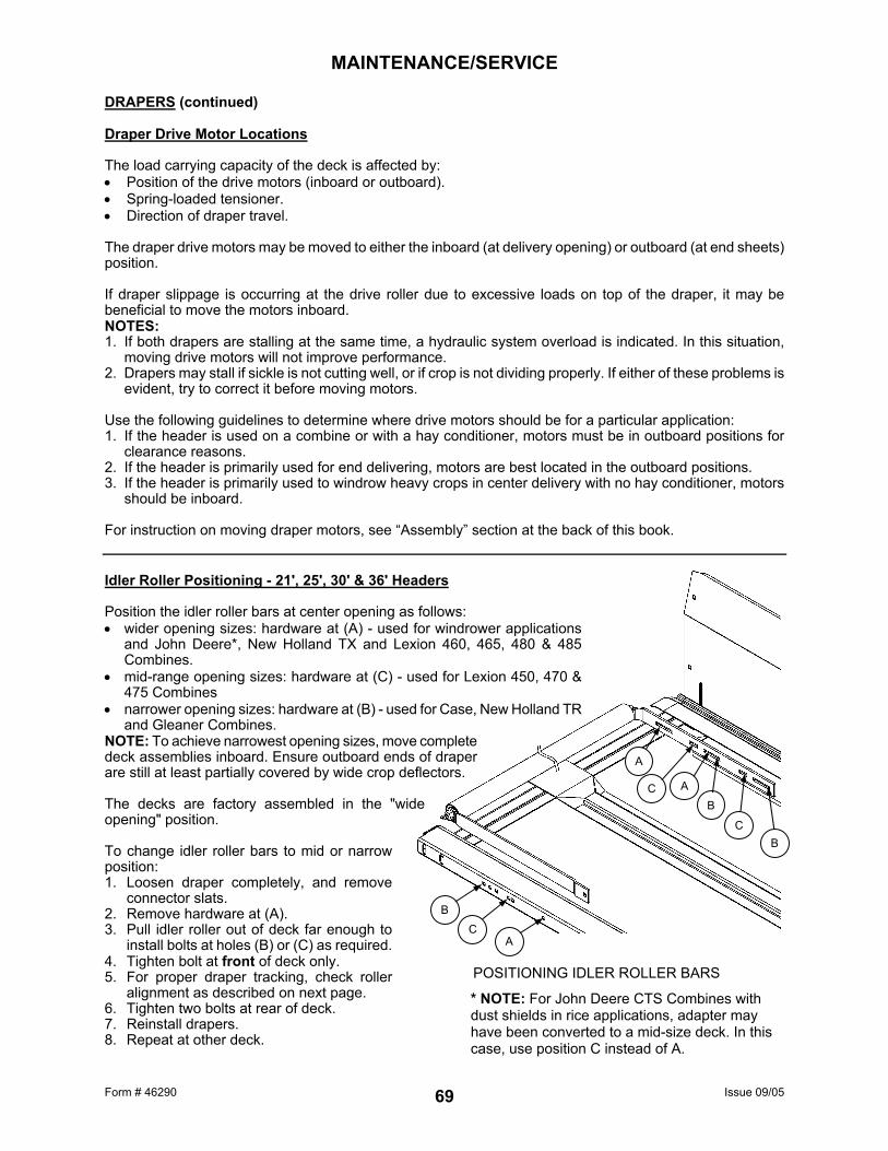
Form # 46290 Issue 09/05 69
POSITIONING IDLER ROLLER BARS
A
A C B
C B
B
C A
MAINTENANCE/SERVICE DRAPERS (continued) Draper Drive Motor Locations The load carrying capacity of the deck is affected by: • Position of the drive motors (inboard or outboard). • Spring-loaded tensioner. • Direction of draper travel. The draper drive motors may be moved to either the inboard (at delivery opening) or outboard (at end sheets) position. If draper slippage is occurring at the drive roller due to excessive loads on top of the draper, it may be beneficial to move the motors inboard. NOTES: 1. If both drapers are stalling at the same time, a hydraulic system overload is indicated. In this situation,
moving drive motors will not improve performance. 2. Drapers may stall if sickle is not cutting well, or if crop is not dividing properly. If either of these problems is
evident, try to correct it before moving motors. Use the following guidelines to determine where drive motors should be for a particular application: 1. If the header is used on a combine or with a hay conditioner, motors must be in outboard positions for
clearance reasons. 2. If the header is primarily used for end delivering, motors are best located in the outboard positions. 3. If the header is primarily used to windrow heavy crops in center delivery with no hay conditioner, motors
should be inboard. For instruction on moving draper motors, see “Assembly” section at the back of this book. Idler Roller Positioning - 21', 25', 30' & 36' Headers Position the idler roller bars at center opening as follows: • wider opening sizes: hardware at (A) - used for windrower applications
and John Deere*, New Holland TX and Lexion 460, 465, 480 & 485 Combines.
• mid-range opening sizes: hardware at (C) - used for Lexion 450, 470 & 475 Combines
• narrower opening sizes: hardware at (B) - used for Case, New Holland TR and Gleaner Combines.
NOTE: To achieve narrowest opening sizes, move complete deck assemblies inboard. Ensure outboard ends of draper are still at least partially covered by wide crop deflectors. The decks are factory assembled in the "wide opening" position. To change idler roller bars to mid or narrow position: 1. Loosen draper completely, and remove
connector slats. 2. Remove hardware at (A). 3. Pull idler roller out of deck far enough to
install bolts at holes (B) or (C) as required. 4. Tighten bolt at front of deck only. 5. For proper draper tracking, check roller
alignment as described on next page. 6. Tighten two bolts at rear of deck. 7. Reinstall drapers. 8. Repeat at other deck.
* NOTE: For John Deere CTS Combines with dust shields in rice applications, adapter may have been converted to a mid-size deck. In this case, use position C instead of A.

Form # 46290 Issue 09/05 70
FIXED ROLLER ALIGNMENT
A
B
C
MAINTENANCE/SERVICE DRAPERS (continued) Draper Tracking Adjustment: Each draper deck has one fixed roller and one spring-loaded roller. The spring-loaded roller is located at the same end of the deck as the draper tensioner, and is self-aligning. Adjustments are not required to this roller. The fixed roller is aligned by re-positioning hardware in the slotted holes in the rear support arm. To ensure square alignment for proper draper tracking, measure dimensions (A) and (B) from roller to channel at front and rear as shown. Align roller by loosening two bolts in rear support (C) and adjusting in slots until dimensions (A) and (B) are: 12’ to 25’ Headers – equal. 30’ & 36’ Headers – Dimension (B) 3 mm (1/8”) less than Dimension (A). If drapers still do not track properly with the settings above, it may be necessary to bias the fixed roller alignment to correct the problem: NOTE: When adjusting the fixed roller, move in 2 to 3 mm increments. Before loosening hardware, scribe a mark on the rear arm and the backsheet to measure the amount the roller moves. • If the draper is tracking back (towards backsheet) at the end of the deck with the fixed roller, increase
dimension (B). • If the draper is tracking ahead (towards cutterbar) at the end of the deck with the fixed roller, decrease
dimension (B). • If the draper is tracking back (towards backsheet) at the end of the deck with the spring-loaded roller,
decrease dimension (B). • If the draper is tracking ahead (towards cutterbar) at the end of the deck with the spring-loaded roller,
increase dimension (B). NOTE: If the fixed roller is positioned too far off of square in an attempt to correct a tracking problem on the spring-loaded roller, tracking at the fixed roller will be adversely affected. In this case, check the draper for squareness and re-punch draper connecting holes if necessary. Idler Roller Maintenance NOTE: When tightening nuts at ends of idler roller, torque to 30 - 45 ft.lbs. (40 - 60 N·m). Over-tightening may cause thread to fail. NOTE: When reassembling idler roller, install both seals (K) with flat face (with writing) out and install bearing (L) with shielded side facing out.
INSTALL SEALS WITH FLAT FACE OUT INSTALL BEARING WITH SHIELDED SIDE OUT
K
L

Form # 46290 Issue 09/05 71
MAINTENANCE/SERVICE Drive Roller Maintenance To replace drive roller bearings:
1. Raise header and reel. CAUTION: Engage header lift cylinder stops and reel props before working under header or reel.
2. On 21’ to 36’ headers, position deck so drive
roller is easily accessible. 3. Loosen and uncouple draper. 4. If drive roller is at end of header, remove drive
roller assembly by sliding spring rod (A) through hole in backsheet and pulling roller out. (Loosen hose clamps to allow slack in hydraulic hoses.) If drive roller is at center opening, remove the bolt holding rear bar in deck and remove roller assembly.
5. Remove bearing assembly from roller tube by tapping on arm at (B) while holding roller. Disassemble by removing bolt (C). NOTE: Retaining disk (P) remains inside roller tube.
6. Clean inside of roller tube and stub shaft (D). Check tube and stub shaft for wear or damage. Replace if necessary.
7. Place retaining ring (E) onto stub shaft (D) and hang it loosely over stub shaft mounting face. IMPORTANT: Retaining ring must be in position on stub shaft before installing bearing into tube.
8. Sub-assemble seal (F), bearing (G) and washer (H) onto stub shaft and secure with lockwasher (J) and bolt (C). IMPORTANT: Install seal (F) with flat face (with writing) out, and install bearing (G) with shielded side out.
9. Remove grease fitting (K) and press on end of stub shaft to install bearing sub-assembly into roller tube. Press in until retaining ring (E) can be installed in groove inside tube. To prevent damage to bearing, do not press the assembly deeper than necessary.
10. Reinstall fitting (K) into stub shaft and grease until grease appears past seal.
11. Reassemble drive roller into deck, re-couple and tighten draper.
NOTE: At drive roller to motor connection, there is a short "through-bore" setscrew (L) on top of setscrew (M). When removing, be sure to engage Allan wrench only far enough to remove setscrew (L) first, then setscrew (M). Deck Height To prevent material from entering drapers and cutterbar, maintain deck height so that draper runs just below cutterbar with maximum 1/32” (1 mm) gap, or with draper deflected down slightly [up to 1/16” (1.5 mm)] to create a seal. Adjust as follows: 1. Loosen tension on drapers. 2. Lift draper up at front edge and loosen two nuts on deck
support (N), two or three per deck, depending on header size.
3. Tap deck up or down relative to supports to achieve setting recommended above.
4. Tighten deck support hardware and tension drapers.
DRIVE ROLLER TO MOTOR CONNECTION
DECK HEIGHT ADJUSTMENT

Form # 46290 Issue 09/05 72
MAINTENANCE/SERVICE REEL AND REEL DRIVE Reel Clearance To Cutterbar Reel finger to sickle guard minimum clearance with reel fully lowered is 5/8" (15 mm), measured at both ends of the cutterbar. Check all possible points of contact between points (X). Depending on reel fore-aft position, minimum clearance can occur at guard tine, hold-down or cutterbar. Check reel clearance whenever the reel fore-aft position or finger pitch is changed. When operating reel with an aggressive finger pitch, be sure that fingers will not contact sickle when flexed back by crop, as at (R). To adjust reel clearance to cutterbar: 1. Raise header and engage header lift cylinder stops.
Lower header onto stops. Lower the reel fully. 2. Loosen and back off nut (A). 3. Turn nut (B) clockwise to increase clearance to
cutterbar, or counter-clockwise to decrease. 4. Tighten nut (A) against nut (B) to secure the
position. 5. Repeat at opposite side. Reel "Frown" Adjustment The reel has been factory adjusted to give more clearance at the center of the cutterbar than at the ends. This compensates for flexing of the reel and header over rough ground. The "frown" is adjusted by repositioning the hardware connecting reel finger tube arms to reel discs. If reel is disassembled for service, adjust positioning of hardware in holes (C) to maintain the proper profile. NOTE: Take these measurements with the reel centered over the cutterbar (see "Reel Position" in Operation section). This will provide adequate clearance at all reel fore-aft positions. NOTE: This adjustment can also be used to compensate for reel tube and cutterbar tolerances. When adjusting, start with the reel arm set closest to the center of the header, and work your way out to the ends, allowing the reel arms to find a natural curve, and positioning the hardware appropriately. NOTE: In some locations, top and bottom bolts in the same reel arm may not be in the same hole position.
A
B
REEL CLEARANCE ADJUSTMENT
REEL "FROWN" ADJUSTMENT
REEL CLEARANCE TO SICKLE (measured at both ends)

Form # 46290 Issue 09/05 73
MAINTENANCE/SERVICE REEL AND REEL DRIVE Plastic Finger Installation and Removal
WARNING: To avoid eye injury caused by broken pieces, wear eye protection when installing or removing plastic fingers.
To install finger: 1. Finger saddle has two pins that snap into holes in finger
tube. Install by positioning finger as shown and pushing straight up. NOTE: Applying loads to finger before tightening hardware may cause finger to break. To avoid shearing off the pins, do not flex finger back and forth after the pins are engaged.
2. Insert nut into recessed pocket (A) in finger. Install screw and tighten to 25 to 30 in.lbs. (2.8 to 3.4 N·m). NOTE: Tighten screw to specified torque. Under tightening will allow finger to move at mount when flexed sideways. Over tightening will strip hardware and may cause finger to crack.
To remove finger: 1. Remove screw. 2. Insert screwdriver at back of finger saddle and
pry back until rear pin clears finger tube. 3. Rotate finger tip forward to remove finger.
1
2
REMOVING PLASTIC FINGERS
INSTALLING PLASTIC FINGERS
A

Form # 46290 Issue 09/05 74
MAINTENANCE/SERVICE REEL AND REEL DRIVE (continued) Centering the Reel Center the reel between the header end sheets by adjusting the reel support arm brace (A). To adjust: 1. Loosen two nuts (E) at front of brace. 2. Position brace (A) as required to center reel. 3. Tighten nuts (E) to 160 ft.lbs. (215 N·m).
Reel Drive Chain Tension Check the reel drive chain tension every 100 hours or annually. In extreme crop conditions like heavy forage or rice, check tension more often. To adjust: 1. Remove drive cover (A) and check chain tension.
See step 3 for proper tension. If adjustment is required:
2. Loosen four bolts (B). 3. Slide motor away from reel shaft until a force of 11
lbs. (50 N) deflects chain 1/8 inch (3 mm) at mid-span.
4. Tighten bolts (B). Reel Drive Chain Lubrication Lubricate full length of chain every 100 hours or annually with Multi-Purpose Grease. Removal of Reel Drive Shaft Tapped holes are provided in reel drive shaft mounting flange for pulling shaft out of reel tube.
E
A
REEL CENTERING ADJUSTMENT
REEL DRIVE CHAIN TENSION

Form # 46290 Issue 09/05 75
MAINTENANCE/SERVICE GAUGE WHEELS – 30’ & 36’ OPTION Wheel Bolts Check and tighten wheel bolts after the first 10 hours of operation and every 100 hours thereafter. Whenever a wheel is removed and re-installed, check torque after one hour of operation. Maintain torque at 80 to 90 ft.lbs. (110 to 120 N⋅m) Follow the proper bolt tightening sequence shown. NOTE: When installing wheel, be sure valve stem (A) points away from wheel support. Tire Inflation Check tire pressure daily. Maintain 100 psi (690 kPa) for gauge wheels with Transport option. Maintain 60 psi (414 kPa) for non-transport gauge wheels.
WARNING: Service tires safely. A tire can explode during inflation and cause serious injury or death. Never
increase air pressure beyond 35 psi (241 kPa) to seat the bead on the rim. Replace the tire if it has a defect. Replace a wheel rim which has cracks, wear or severe rust. Never weld a wheel rim. Make sure all the air is removed from a tire before removing the tire from a rim. Never use force on an inflated or partially inflated tire. Make sure the tire is correctly seated before inflating to operating pressure. Do not remove, install or make repairs to a tire on a rim unless you have the proper equipment and experience to perform the job. Take the tire and rim to a qualified tire repair shop. If the tire is not in correct position on the rim, or is too full of air, the tire bead can loosen on one side, causing air to leak at high speed and with great force. An air leak of this nature can thrust the tire in any direction, endangering anyone in the area. (A) - Use a safety cage if available. (B) - Do not stand over tire. Use a clip-on chuck
and extension hose.
BOLT TIGHTENING SEQUENCE
A 1
3
5
2 4
6
SERVICE TIRES SAFELY

Form # 46290 Issue 09/05 76
MAINTENANCE/SERVICE HAY CONDITIONER Hay Conditioner Drive Chain Lubrication Lubricate chain daily with lightweight oil (SAE 30). Hay Conditioner Drive Chain Tension Check hay conditioner drive chain tension after the first 2 hours operation and every 100 hours thereafter. To check chain tension: Place a straightedge across idler sprockets as shown. Light pressure at mid-span should produce 5/8 in. (15 mm) deflection. If adjustment is required: 1. Loosen nut (A). 2. Back off nut (D) and turn nut (E) to push
sprocket rearward to increase tension to above specification. Do not over-tighten.
3. Tighten nuts (A) and (D) to secure the position.
Hay Conditioner Roll Timing Rolls must be timed to prevent contact between bars. Bars of one roll must be approximately centered between bars of the other roll as illustrated. When installing roll drive chain: 1. Rotate rolls to approximately correct timing. 2. Install chain. 3. Set roll timing as follows: • Loosen four nuts (A) at upper roll sprocket. • Rotate sprocket to achieve best roll timing. • Tighten nuts (A) to secure the position. Hay Conditioner Pulley Clean-Out Bolts When installing hay conditioner drive belt, ensure mounting bracket (B) for clean-out bolts on lower roll driven pulley is not interfering with belt travel. Also, ensure clean-out bolts are centered in pulley grooves. Mounting bracket can be adjusted laterally to properly position bolts.
A
D
E
CONDITIONER DRIVE CHAIN TENSION
B
A
ROLL TIMING ADJUSTMENT

Form # 46290 Issue 09/05 77
MAINTENANCE/SERVICE MAINTENANCE SCHEDULE The following maintenance schedule is a listing of periodic maintenance procedures, organized by service intervals. For detailed instruction, see the specific headings in Maintenance/Service section. Use "Recommended Lubricants" as specified under that heading. SERVICE INTERVALS The recommended service intervals are in hours of operation. Use the hour meter in the windrower or combine cab to indicate when the next service interval has been reached. IMPORTANT: Recommended intervals are for average conditions. Service header more often if operated under adverse conditions (severe dust, extra heavy loads, etc.) Regular maintenance is the best insurance against early wear and untimely breakdowns. Following this schedule will increase machine life. Where a service interval is given in more than one time frame, e.g. "100 Hours or Annually", service the header at whichever interval is reached first.
CAUTION: Carefully follow safety messages given under "Service Procedures".
AT FIRST USE: See "Break-In Period" in Operation section. 10 HOURS OR DAILY 1. Grease secondary driveline (combine
applications) 2. Check hydraulic hoses, lines and
components for leaks
3. Oil sickle (except in sandy conditions) 4. Check sickle sections, guards and hold-downs 5. Oil hay conditioner drive chain 6. Check gauge wheel tire pressure.
25 HOURS 1. Grease sickle head 50 HOURS 1. Grease cross shaft center supports (double sickle.) 2. Grease reel support bushings (R/H end of split
pick-up reel header)
3. Grease hay conditioner roll bearings 4. Grease hay conditioner belt idler pulley
bearings. 100 HOURS OR ANNUALLY * 1. Grease draper roller bearings 2. Grease reel drive support bearings 3. Grease pick-up reel drive cam 4. Grease reel tail support bearing 5. Grease split reel connector block 6. Grease sickle drive shaft support bearings 7. Grease cross shaft support bearings (double sickle) 8. Grease upper cross auger support bearing
(option)
9. Grease gauge wheel pivot bushings (option) 10. Grease gauge roller bearings (option) 11. Check sickle drive belt tension 12. Check wobble box mounting bolts 13. Check wobble box lubricant level 14. Check reel drive chain tension 15. Grease reel drive chain 16. Check hay conditioner drive chain tension 17. Check gauge wheel bolt torque.
500 HOURS OR ANNUALLY * 1. Grease gauge wheel hub bearings (option) END OF SEASON: See "Storage Procedure" in Operation section. 1000 HOURS OR 3 YEARS 1. Change wobble box lubricant. * It is recommended that Annual Maintenance be done prior to start of operating season.

Form # 46290 Issue 09/05 78
MAINTENANCE RECORD Header Serial No.___________________ Hay Conditioner Serial No._________________ Combine this record with Windrower or Combine Maintenance Record for "complete unit" service. See Maintenance/Service section for details on each procedure. Copy this page to continue record. (C) – Combine Applications (D) – Double Sickle Headers (O) – Optional Equipment
ACTION: - Check - Lubricate - Change
Hour Meter Reading:
Serviced By: Maintenance Procedure
BREAK-IN See “Break-In Period” in Operation section for checklist. 10 HOURS OR DAILY Secondary Driveline (C) Sections, Guards, Hold-downs Sickle Assembly Hydraulic Hoses and Lines Tire Pressure (O) Hay Cond. Drive Chain (O)
25 HOURS Sickle Head
50 HOURS CrossShaft Center Supp. (D) P.U. Reel Support (30&36’) Conditioner Roll Bearings (O) Cond. Belt Idler Pulley Brg. (O)
100 HOURS OR ANNUALLY Draper Roller Bearings Reel Drive Support Bearings Pick-Up Reel Drive Cam Reel Tail Support Bearing Split Reel Connector Block Sickle Drive Shaft Bearings CrossShaft End Bearings (D) Sickle Drive Belt Tension Wobble Box Bolts & Lube Reel Drive Chain Tension Reel Drive Chain Cond. Drive Chain Tension (O) Gauge Roller Bearings (O) Upper Cross Auger Brg. (O) Gauge Wheel Bolt Torque (O) Gauge Wheel Pivot Bush. (O)
500 HOURS OR ANNUALLY Gauge Wheel Hub Brgs. (O)
1000 HOURS OR 3 YEARS Wobble Box Lubricant

Form # 46290 Issue 09/05 79
TROUBLESHOOTING SYMPTOM PROBLEM SOLUTION REF. CROP LOSS AT CUTTERBAR Does not pick-up down crop. Cutterbar too high. Lower cutterbar. 23 Header angle too flat. Steepen header angle. 27 Reel too high. Lower reel. 33 Reel too far back. Move reel forward. 34 Ground speed too fast
for reel speed. Reduce ground speed or
increase reel speed. 25
33 Reel fingers not lifting
crop sufficiently. Increase finger pitch
aggressiveness. 35
Install lifter guards. * Heads shattering or breaking off.
Reel speed too fast. Reduce reel speed. 33
Reel too low. Raise reel. 33 Ground speed too fast. Reduce ground speed. 25 Crop too ripe. Operate at night when
humidity is higher. ---
Cut grain falling ahead of cutterbar.
Ground speed too slow. Increase ground speed. 25
Reel speed too slow Increase reel speed. 33 Reel too high. Lower reel. 33 Cutterbar too high. Lower cutterbar. 23 Reel too far forward. Move reel back on arms. 34 Cutting at speeds over 6
mph (10 km/h) with high-torque (11 tooth) reel drive sprocket.
Replace with high speed (17 tooth) reel drive sprocket.
33
Worn or broken sickle
components. Replace. 60
Strips of uncut material. Crowding uncut crop. Allow enough room for crop
to be fed to cutterbar. ---
Broken sickle sections. Replace. 60 Excessive bouncing at normal field speed.
Float set too light. Adjust float. 26
Divider rod running down standing crop.
Divider rods too long. Install shorter rods. 24
* See your MacDon dealer.
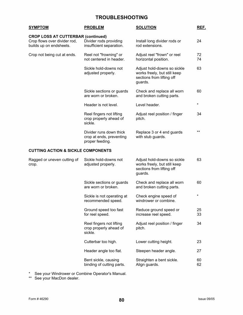
Form # 46290 Issue 09/05 80
TROUBLESHOOTING SYMPTOM PROBLEM SOLUTION REF. CROP LOSS AT CUTTERBAR (continued) Crop flows over divider rod, builds up on endsheets.
Divider rods providing insufficient separation.
Install long divider rods or rod extensions.
24
Crop not being cut at ends. Reel not "frowning" or
not centered in header. Adjust reel "frown" or reel
horizontal position. 72
74 Sickle hold-downs not
adjusted properly. Adjust hold-downs so sickle
works freely, but still keep sections from lifting off guards.
63
Sickle sections or guards
are worn or broken. Check and replace all worn
and broken cutting parts. 60
Header is not level. Level header. * Reel fingers not lifting
crop properly ahead of sickle.
Adjust reel position / finger pitch.
34
Divider runs down thick
crop at ends, preventing proper feeding.
Replace 3 or 4 end guards with stub guards.
**
CUTTING ACTION & SICKLE COMPONENTS Ragged or uneven cutting of crop.
Sickle hold-downs not adjusted properly.
Adjust hold-downs so sickle works freely, but still keep sections from lifting off guards.
63
Sickle sections or guards
are worn or broken. Check and replace all worn
and broken cutting parts. 60
Sickle is not operating at
recommended speed. Check engine speed of
windrower or combine. *
Ground speed too fast
for reel speed. Reduce ground speed or
increase reel speed. 25
33 Reel fingers not lifting
crop properly ahead of sickle.
Adjust reel position / finger pitch.
34
Cutterbar too high. Lower cutting height. 23 Header angle too flat. Steepen header angle. 27 Bent sickle, causing
binding of cutting parts. Straighten a bent sickle.
Align guards. 60
62 * See your Windrower or Combine Operator's Manual. ** See your MacDon dealer.

Form # 46290 Issue 09/05 81
TROUBLESHOOTING SYMPTOM PROBLEM SOLUTION REF. CUTTING ACTION & SICKLE COMPONENTS Ragged or uneven cutting of crop. (continued)
Cutting edge of guards not close enough or parallel to sickle sections.
Align guards. 62
Double sickles improperly
timed. Time sickles. 67
Tangled/tough to cut crop. Install stub guards. 62/63 Reel too far back. Move reel forward. 34 Loose sickle drive belt. Adjust drive belt tension. 65/66 Sickle plugging. Reel too high or too far
forward. Lower reel or move reel
rearward. 33
34 Ground speed too slow. Increase ground speed. 25 Loose sickle drive belt. Adjust drive belt tension. 65/66 Improper sickle hold-down
adjustment. Adjust hold-down so sickle is
held against guard cutting surface.
63
Dull or broken sickle
sections. Replace. 60
Bent or broken guards. Align or replace. 62 Reel fingers not lifting
crop properly ahead of sickle.
Adjust reel position / finger pitch. 34
Steel pick-up fingers
contacting sickle. Increase reel clearance to
cutterbar, or adjust "frown". 72
Header float too heavy. Adjust springs for lighter float. 26 Mud or dirt build-up on
cutterbar. Raise cutterbar by lowering skid
shoes. 23
Flatten header angle. 27 Mud build-up on inboard
side of sickle head. Remove skid shoe under sickle
head to prevent build-up. 61
Ends plug due to wet crop
build-up on front portion of wide deflectors.
Install special narrow deflectors. 88
Sickle is not operating at
recommended speed. Check engine speed of
windrower or combine. *
* See your Windrower or Combine Operator's Manual.

Form # 46290 Issue 09/05 82
TROUBLESHOOTING SYMPTOM PROBLEM SOLUTION REF. CUTTING ACTION & SICKLE COMPONENTS (continued) Excessive header vibration. Sickle not operating at
recommended speed. Check engine speed of
windrower or combine. *
Double sickles
improperly timed. Time sickles. 67
Excessive sickle wear. Replace sickle. 60 Loose or worn sickle
head pin or drive arm. Tighten or replace parts. 61
Excessive breakage of sickle sections or guards.
Cutterbar operating too low in stony conditions.
Raise cutterbar, using skid shoes.
23
Header float is set too
heavy. Adjust float springs for
lighter float. 26
Bent or broken guard. Straighten or replace. 62 Header angle too steep. Flatten header angle. 27 Sickle back breakage. Bent or broken guard. Straighten or replace. 62 Worn sickle head pin. Replace. 61 Dull sickle. Replace. 60 REEL DELIVERY Reel not releasing crop. In heavy crop, fingers
starting to flip over before releasing crop.
Move to a more aggressive finger pitch position.
35
Reel speed too fast. Reduce speed of reel to
allow crop to fall onto drapers properly. Reel speed should be slightly faster than ground speed.
33
Reel too low. Raise reel. 33 Reel too far back. Move reel forward. 34 Wrapping on reel end. Finger pitch too
aggressive. Decrease finger pitch
aggressiveness. 35
Reel too low. Raise reel. 33 Reel speed too fast. Reduce reel speed. 33 * See your Windrower or Combine Operator's Manual.

Form # 46290 Issue 09/05 83
TROUBLESHOOTING SYMPTOM PROBLEM SOLUTION REF. REEL (continued) Wrapping on reel end (continued)
Reel not centered in header.
Center reel in header. 74
Reel releases crop too quickly.
Finger pitch not aggressive enough.
Increase finger pitch aggressiveness.
35
Reel too far forward. Move reel back. 34 Reel will not lift. Reel lift couplers are
incompatible. Change quick coupler. ---
Reel will not turn. Control set at 0. Activate reel speed control. * Quick couplers not
properly connected. Connect couplers. *
Final drive chain
disconnected. Connect chain. 74
Reel motion is uneven or stalls in heavy crop.
Reel speed too fast. Reduce reel speed. 33
Reel fingers not aggressive enough.
Move to a more aggressive finger pitch notch.
35
Reel too low. Raise reel. 33 Relief valve on
windrower or combine (not on combine adapter) has low relief pressure setting.
Increase relief pressure to 2000 psi.
*
Low oil reservoir level on
windrower or combine. (NOTE: Sometimes more than one reservoir.)
Fill to proper level. *
Relief valve malfunction. Replace relief valve. - Cutting tough crops with
high-speed (17 tooth) reel drive sprocket.
Replace with high torque (11 tooth) reel drive sprocket.
33
Premature failure of cam arm bearings.
Cam arms bent, causing bearing misalignment.
Straighten cam arms to set bearings parallel.
-
HEADER Header lift insufficient. Low relief pressure. Increase relief pressure. * * See your Windrower or Combine Operator's Manual.

Form # 46290 Issue 09/05 84
TROUBLESHOOTING SYMPTOM PROBLEM SOLUTION REF. DRAPERS & DECKS Draper will not drive, and/or hydraulic decks will not shift.
Drapers are loose. Tighten drapers. 68
Drive or idler roller
wrapped with material. Loosen draper and clean
rollers. 68
Slat or connector bar
jammed by frame or material.
Loosen draper and clear obstruction.
68
Insufficient clearance
between decks. Adjust deck stops. 30,31
Roller bearing seized. Replace. 71 Low hydraulic oil. Fill reservoir to full level. * Incorrect relief setting at
flow control valve. Adjust relief setting. *
Draper stalling. Material not feeding
evenly off sickle. Lower reel.
Install stub guards.
33 63
Wet crop build-up on
front portion of wide deflectors.
Install special narrow deflectors.
88
Material accumulates inside or under front edge of draper.
Deck height improperly adjusted.
Adjust deck height. 71
WINDROW FORMATION - GRAIN Heads on ground (flowered out).
Draper speed too slow. Increase draper speed. 27
Draper angle too flat. Increase draper angle. 27 Ground speed too slow. Increase ground speed. 25 Crop too ripe. Cut material before too
mature. ---
Hollow in center. Draper speed too slow. Increase draper speed. 27 Delivery opening too
wide. Decrease delivery opening
width. 27/28
* See your Windrower or Combine Operator's Manual.

Form # 46290 Issue 09/05 85
TROUBLESHOOTING SYMPTOM PROBLEM SOLUTION REF. WINDROW FORMATION - GRAIN (continued) Heads in center (too much herringbone).
Draper speed too fast or draper angle too steep.
Reduce draper speed and/or decrease draper angle.
27
Ground speed too fast. Reduce ground speed. 25 Crop too green. Allow to mature. --- All heads to one side. Crop leaning to one side
and reel too slow. Increase reel speed to
reorient crop parallel to draper slats and/or increase finger pitch aggressiveness.
33 35
Uneven windrow (any crop condition).
Ground speed too fast for drapers, causing heads to fan out and causing crop to come off draper in bunches.
Reduce ground speed or increase draper speed.
25 27
Reel too low. Raise reel. 33 Reel too fast. Reduce reel speed. 33 Draper angle too steep. Decrease draper angle. 27 Material not feeding
evenly off of sickle. Lower reel.
Install stub guards.
33 63
Reel speed too slow
causing bats to push crop forward.
Increase reel speed so reel gathers crop, pushing it back.
33
Uneven windrow in down crop.
Reel finger pitch not aggressive enough, causing hesitation at endsheet corners.
Increase finger pitch aggressiveness to 1 or 2 notches past 90°.
35
Uneven windrow in standing crop.
Reel finger pitch too aggressive, disturbing crop flow on draper.
Decrease finger pitch aggressiveness to 2 notches retarded from 90°.
35
Reel too far back,
disturbing crop flow on draper.
Move reel forward. 34

Form # 46290 Issue 09/05 86
TROUBLESHOOTING SYMPTOM PROBLEM SOLUTION REF. HAY CONDITIONER Hay conditioner rolls will not turn.
Obstruction or wad in conditioner rolls.
Turn mechanism in reverse and remove wad.
47
Drive belt too loose. Tighten conditioner drive
belt. 16
Over-conditioning of crop. Excessive intermesh of
hay conditioner rolls. Reduce intermesh of rolls. 41
Under-conditioning of crop. Insufficient intermesh of
hay conditioner rolls. Increase intermesh of rolls. 41
WINDROW FORMATION - HAY Windrow too wide. Windrow forming shields
positioned too far apart. Position shields closer
together. 44
Windrow too narrow. Forming shields
positioned too close together.
Position shields farther apart.
44
Deflector fins on forming
shield improperly adjusted.
Adjust fins.
44
Windrow uneven. Forming shields too low. Raise forming shields. 44 Deflector fins on forming
shield improperly adjusted.
Adjust fins. Add extra fins for widest windrows.
44
Windrow lacks shape. Forming shields too high. Lower forming shields. 44 Deflector fins on forming
shield improperly adjusted.
Adjust fins.
44
Hay conditioner not picking up all crop.
Conditioner rolls positioned too high.
Lower conditioner rolls. 42
Hay conditioner bottom roll being damaged by rocks.
Conditioner rolls positioned too low.
Raise conditioner rolls. 42
Running over previous windrow or irrigation row when turning.
Model 9000 tractor wheelbase too long.
Reverse walking beam. **
** - See your MacDon dealer.

Form # 46290 Issue 09/05 87
CUTTING EDIBLE BEANS: TROUBLESHOOTING
SYMPTOM PROBLEM SOLUTION
CUTTING EDIBLE BEANS Header stripping plants- Complete or partial plants left behind.
Header being carried off ground.
Lower header to ground and run on skid shoes and/or cutterbar.
Float set too light - rides on high spots and does not get back down soon enough.
Set float for: 100-150 lbs. - dry ground 50-100 lbs. - wet ground Float should be lighter for light soils and heavier for hard heavy soil areas.
Reel being operated too high.
Fully retract reel cylinders Operate reel at max. down position in all conditions unless excessive wrapping occurs in a green matted viney crop.
Reel too high with cylinders fully retracted.
Adjust reel height with cylinders fully retracted to obtain minimum clearance to knife. Important - maintain adequate clearance to prevent finger from getting in knife.
Finger pitch not aggressive enough.
Adjust finger pitch: Start with 1-2 notches more aggressive than mid-position. -readjust reel fore and aft if necessary. -readjust reel clearance with cylinders fully retracted.
Reel too far back on reel support arms.
Move reel forward until the fingertips skim the soil surface with header on ground and center link properly adjusted. Start in hole #6 to #8 from front of support armRe-adjust reel height with cylinders retracted if necessary. Check finger clearance to ground. - Adjusting reel forward gets reel closer to ground and back will move reel away from ground.
Header angle too shallow. Lengthen center link to max. length to start with. Decrease center link length if header pushes too much dirt. Tip: Use variable header angle feature at bottom end of header lift stroke to vary header angle on the go. -Once header touches the ground the header angle will be increased if the header lift cylinders are further retracted. -With header on the ground the header will get shallower as the lift function is actuated until the header is picked up by the tractor. - Header angle can be varied up to 4 degrees by fully retracting lift cylinders from when header touches the ground. Note: If frequent adjustment of the center link is necessary, a hydraulic center link is available.

Form # 46290 Issue 09/05 88
CUTTING EDIBLE BEANS: TROUBLESHOOTING
SYMPTOM PROBLEM SOLUTION
Header stripping plants- Complete or partial plants left behind (continued).
Reel too slow. Adjust reel speed to be marginally faster than ground speed Tip: Look at perimeter of reel discs. they should appear to be being driven by the ground - If they look like they are skidding relative to ground, the reel is turning too slow - If they look like they are spinning excessively relative to ground, reel speed may be too fast and create shattering.
Ground speed too fast. Lower ground seed Start at 3.0 - 3.5 mph and adjust as required. Tips: -When cutting very light crop ground speed may have to be reduced to allow reel to pull in small and short plants. -Reel speed may be increased if it does not create excessive shattering.
Header skid shoes adjusted too low.
Raise skid shoes to max. up position
Dirt packs on bottom of cutterbar and raises cutterbar off the ground.
Install plastic wear strips on bottom of cutterbar and skid shoes.
Dirt still packing on bottom of cutterbar with poly wear strips on cutterbar and raises cutterbar off the ground.
Ground too wet. Wait until top of ground starts to turn grey or manually clean the bottom of cutterbar when accumulation gets unacceptable.
Plastic wear strip for cutterbar has been installed over top of steel wear plates.
Remove steel cutterbar wear plates when installing the plastic wear strips for cutterbar.
Header not level. Level Header – see Tractor Operator’s Manual.
Dirt builds up between plastic cutterbar wear strips and causes header to cut higher off the ground.
Reduce spacing between clips.
Knife sections worn out and have no serrations left causing plants to slip out of guards and sections.
Replace sections or complete knife. Tip: -Coarse serrated sections last longer when operating in dirty conditions. -Fine serrated sections loose their serrations faster and will leave behind uncut plants.
Knife sections have edges broken off.
Replace sections or complete knife if required.

Form # 46290 Issue 09/05 89
CUTTING EDIBLE BEANS: TROUBLESHOOTING
SYMPTOM PROBLEM SOLUTION
Header stripping plants- Complete or partial plants left behind (continued).
Parts of vines get caught in regular guard tip while reel is trying to lift the vines above the knife and end up getting cut off. (This is more prevalent when cutting row-cropped beans that have been hilled due to cultivating.
Install stub guard kit. Reel has a better chance of lifting the crop mat above the knife without any pods being cut by the knife.
Plastic cutterbar wear strips slip out of retaining clips.
Guard bolts at retaining clips not tightened properly and/or clips not biting in plastic poly strips.
Hit the pointed tip of the clip with a large hammer to cause retainer clip to bite in plastic poly strips when installing them. Retighten the guard bolts.
Excessive losses at dividers Divider rod running down crop and shattering pods.
Install short divider rod.
Excessive amount of vines and plants run up divider and endsheet up to cylinder and either fall into or outside header in lumps.
Install long divider rod.
Excessive shattering of pods by the reel.
Reel running too fast. Reduce reel speed.
Bean pods are too dry. Cut at night with heavy dew once pods have softened up.
Reel finger pitch not aggressive enough.
Make fingers more aggressive. -Check reel clearance to knife and cutterbar. -Check reel finger clearance to ground. -Reel too far forward of cutterbar C-section.
Crop accumulating at guards and not moving rearward onto drapers.
Reel finger pitch not aggressive enough.
Make fingers more aggressive. -Check reel clearance to knife and cutterbar. -Check reel finger clearance to ground. -Reel too far forward of cutterbar C-section.
Reel too high relative to knife.
Re-adjust reel minimum height with cylinders fully retracted.
Cutterbar pushing too much trash and dirt.
Header too heavy. Readjust float to make header lighter. -Check both ends of header
Header angle too steep. Decrease header angle by adjusting header lift cylinders until they begin to lift header off the ground. If this is not enough, then shorten the center link to flatten the header angle range that the lift cylinders work through.
Regular guards push dirt and plug up with trash or plug up with trash and then push dirt.
Install stub guard kit. Stub guard will prevent plugging when in excessive trash. Stub guard bottom is ~15-20 mm higher than regular guard for the same header angle and knife section height.

Form # 46290 Issue 09/05 90
CUTTING EDIBLE BEANS: TROUBLESHOOTING
SYMPTOM PROBLEM SOLUTION
Cutterbar pushing too much trash and dirt (continued).
Improper support for header.
Install center skid shoes on header. This reduces the ground pressure and reduces the possibility of pushing excessive amounts of dirt.
Cutterbar pushing too much dirt in certain locations for length of field.
Tire tracks or row crop ridges caused by seeding or spraying operations. Rolling land along length of field due to cultivating.
Cut at angle to ridges or crop rows to allow knife and guards to clean out better. When cutting in line with tracks or ridges the same guards and sections have to cut in dirt for the whole length of the field. Cutting at an angle shifts these ridges through all guards and prevents pushing dirt. Cut at 90° to undulations, provided knife floats across without digging in.
Cutterbar fills up with dirt. Excessive gap between top of front of draper and cutterbar.
Adjust front deck hooks to obtain proper clearance between cutterbar and draper. If cutterbar still fills up with dirt, raise header to max. up position at each end of field or as required and shift decks back and forth to help clean out cutterbar. Most dirt will fall out without manually having to clean drapers.
Plant vines pinched between top of draper and cutterbar.
Cutterbar has filled up with trash in excessively dirty conditions with draper to cutterbar gap properly adjusted.
Raise header to max up position at each end of field or as required and shift decks back and forth to help clean out cutterbar. Most dirt will fall out without manually having to clean drapers.
Shifting of decks with header raised up does not clean out cutterbar debris.
Dirt and trash is too wet to slide out of cutterbar cavity on its own. Manually remove debris from cutterbar cavity immediately when noticing material between draper and cutterbar or this will damage drapers.
Reel carries over odd plants in same location.
Reel fingers (steel) bent and hook plants out of the crop flow on drapers.
Straighten fingers (steel).
Dirt accumulation on end of fingers do not let plants slide off fingers over drapers
Reel too low relative to the ground. -Adjust reel fore and aft location to move fingers out of the ground.
Reel carries over excessive amounts of plants or wads.
Too much accumulation of crop on drapers (up to height of reel center tube)
Speed up drapers to thin out amount of material on drapers. This is aggravated when double swathing. Higher draper speeds have to be used when double swathing.
Finger pitch too retarded. Increase finger pitch to move finger flip-over point out of the crop flow. Reducing the finger pitch takes the fingers that are starting to flip over lower into crop flow.
Excessive amount of vines and plants or weeds cause reel to wrap up.
Raise reel a slight amount when getting into a patch of viney weeds or green viney crop.
Excessive guard breakage. Header float too heavy. Adjust float to make header lighter.
Excessive amount of rocks in field.
Try using stub guards if using regular guards. Tip: Experiment with a few guards on a section of cutterbar to compare the performance of the two different styles of guards.

Form # 46290 Issue 09/05 91
OPTIONS AND ATTACHMENTS HYDRAULIC DECK SHIFT PACKAGE WholeGoods order number: B2687 (for combines and New Holland Bi-Directional Tractors also order Wiring Harness Adapter B2407) Installation of this kit converts 21' to 36' manual deck shift units to provide in-cab control of deck position and draper rotation. This feature allows double windrowing to permit larger capacity combines to pick up two windrows in a single pass. Installation instructions are provided with the kit. NARROW OPENING KIT WholeGoods order number: B2738 Installation of this kit on 12’ to 18’ headers reduces delivery opening width to 37.5” or 45.5” (955 or 1155 mm). This kit is also required when converting a 30’ or 36’ windrower header to a combine header for Case, Gleaner or New Holland TR Combines. Installation of this kit on 30’ or 36’ windrower headers reduces delivery opening width to range between 30.5” and 45.5” (775 to 1155 mm). Note that draper motors must be moved to outboard position when kit is installed. Installation instructions are provided with the kit. HYDRAULIC FORE-AFT REEL POSITIONER WholeGoods order number: 12’ to 25’ Headers – B2821, 30’ & 36’ Headers – B2822 Combine headers also require a hydraulic coupler completion package:
Case – B2825, John Deere – B2826, New Holland – B2827 Windrower Headers also require installation of the following kits on the tractor:
B2960 Optional Hydraulics Base Kit and B2961 Reel Fore-Aft Hydraulic Kit. Installation of this kit converts manual fore-aft units to provide in-cab adjustment of reel fore-aft position. This feature shortens header preparation time for truck transport, often used in mobile custom harvest operations. Installation instructions are provided with the kits. 742 HAY CONDITIONER WholeGoods order number: C1771 – For use with MacDon 9000 Series, Westward 9000 Series, Prairie Star 4900 Series and Premier 2900 Series Windrower Tractors. C1772 – For use with Model 802 Adapter for New Holland 9030 or TV140 Bi-Directional Tractors. The Model 742 hay conditioner is available for double sickle headers only. Header mounted with intermeshing steel rolls, the conditioner crimps plant stems in several places, allowing moisture release for quicker drying. Information on attaching, operating and servicing the hay conditioner is included throughout this manual.

Form # 46290 Issue 09/05 92
OPTIONS AND ATTACHMENTS FORMING RODS (Center Opening) WholeGoods order number: B2686 Forming rods assist formation of the desired windrow when a hay conditioner is not installed, for example in grass seed. See page 36.
END DELIVERY FORMING RODS WholeGoods order number: B2774 End delivery forming rods provide larger gap between windrow and standing crop when end delivering.
TALL CROP DIVIDER WholeGoods order number: B2659 Tall crop dividers extend the standard dividers to provide clean crop dividing and reel entry in tall crops.
FLOATING DIVIDER WholeGoods order number: Left Hand – B4367 Right Hand – B4368 Floating dividers, available separately for left or right hand end of header, extend the separation of crop to a point in front of the reel. This can be beneficial in short (up to 75 cm [30 in.]) lodged or standing crop. The dividers are also effective in tall standing crop. This attachment is not recommended for tall lodged crops. Installation instructions are provided with the kit.
SPECIAL NARROW DEFLECTORS WholeGoods order number: B4723 In heavy, wet and/or green crops such as forage and canola, these special deflectors prevent crop build-up that can occur on wider deflectors. This build-up can cause sickle plugging and draper stalling. These deflectors are standard on 12’ & 15’ Stub Guard Headers.

Form # 46290 Issue 09/05 93
UPPER CROSS AUGER (15’ & 18’ SHOWN)
STUB GUARDS
PLASTIC WEAR STRIPS & SHOES
OPTIONS AND ATTACHMENTS PLASTIC WEAR STRIPS & SHOES WholeGoods order number: 12’ to 25’ Headers – B2688 30’ & 36’ Headers – B2866 For use in conditions where soil adheres to steel. Plastic wear strips replace the steel wear plates under cutterbar, while plastic shoes attach to existing steel skid shoes. Installation instructions are included with the kit. CUTTERBAR POLY WEAR STRIPS “973 Style” WholeGoods order number: 12’ Header – B4788 15’ Header – B4789 18’ Header – B4790 21’ Header – B4778 25’ Header – B4779 30’ Header – B4780 36’ Header – B4781 This attachment is recommended for cutting on the ground in conditions where soil adheres to steel. UPPER CROSS AUGER WholeGoods order number: 15’ Header – B2594 18’ Header – B2595 21’ Header – B4419 25’ Header – B4421 30’ Header – B4423 36’ Header – B4425 For tall or bulky crops, the upper cross auger will aid crop flow across the header and through the delivery opening. Installation instructions are included with the cross auger. Maintenance and operating instructions are included in this manual. STUB GUARD CONVERSION KIT WholeGoods order number: 12’ & 15’ Header – B2598 18’ Header – B2599 21’ Header – B2619 25’ Header – B2763 30’ Header – B2764 36’ Header – B2765 Stub guards, complete with top guides and adjuster plates are designed to cut tough crops. Installation and adjustment instructions are included with the kit.
CUTTERBAR POLY WEAR STRIPS

Form # 46290 Issue 09/05 94
OPTIONS AND ATTACHMENTS
GAUGE WHEELS WholeGoods order number: B2749 Spring loaded gauge wheels are available for the 30 and 36 foot headers. Gauge wheels improve end-to-end float, allowing larger headers to better follow ground contours. Installation instructions are included with the gauge wheels. Maintenance and operating instructions are included in this manual. GAUGE ROLLERS WholeGoods order number: B2772 Gauge rollers are available for situations where skid shoes wear too quickly. ADJUSTABLE SKID SHOES – OUTBOARD WholeGoods order number: B2767 Recommended for cutting on the ground, these skid shoes are available as an attachment for 30’ & 36’ headers. Standard equipment for 12’ to 25’ headers. ADJUSTABLE SKID SHOES – INBOARD WholeGoods order number: B2768 Recommended for cutting on the ground, these inboard skid shoes are standard equipment for double sickle windrower headers under 30’. They are available as an attachment for all other windrower headers, but cannot be used on combine headers.
GAUGE ROLLERS
GAUGE WHEELS – 30 & 36’ HEADERS
ADJUSTABLE SKID SHOES – OUTBOARD
ADJUSTABLE SKID SHOES – INBOARD WINDROWER HEADERS

Form # 46290 Issue 09/05 95
OPTIONS AND ATTACHMENTS GAUGE WHEELS / SLOW SPEED TRANSPORT – 30’ & 36’ HEADERS WholeGoods order number: C1681 Available for 30’ & 36’ headers as an alternative to the standard gauge wheel package described on previous page. This option allows pivoting the gauge wheels 90º to allow towing the header from the left end. Installation and operating instructions are provided with the option package. TRANSPORT KIT – 21’ & 25’ HEADERS WholeGoods order number: C1755 Available for 21’ & 25’ headers to allow towing the header behind the windrower tractor. A booklet containing Installation Instructions, Operating Instructions and Parts Listings is provided with the option package. AUXILIARY FLOAT SPRING KIT Wholegoods order number: B2773 Required to provide adequate float for heavier headers in windrowing applications. NOTE: 36’ Double Sickle headers require four auxiliary float spring kits. See the Windrower Tractor Parts Catalog for serviced components of kit. ADJUSTABLE OUTBOARD SKID SHOES WITH POLY COVER “973 style” WholeGoods order number: B4389 Available as an attachment for use with 972 Headers, these skid shoes are recommended for cutting on the ground. INNER SKID SHOES WITH POLY COVER “973 style” WholeGoods order number: 12’ to 25’ Headers – B4786 30’ & 36’ Headers – B4787 Recommended for cutting on the ground in conditions where soil adheres to steel.

Form # 46290 Issue 09/05 96
OPTIONS AND ATTACHMENTS COMBINE HEADER / WINDROWER HEADER CONVERSION KITS For headers in windrower configuration, a conversion kit is available to adapt single or double sickle drive to combine (straight-cut) configuration. A similar package is available to convert from combine sickle drive configuration to windrower. This package also includes linkage supports required for attachment to MacDon built windrowers. Instruction # 46532 is provided with the kit. For converting double sickle headers from combine to windrower, order the appropriate conversion bundle plus pulleys 38550 and 38551. (NOTE: Pulleys 38550 and 38551 are present on the Lexion combine configured double sickle header.) For converting double sickle headers from windrower to combine, order the appropriate conversion bundle plus pulleys according to the following chart: (NOTE: Pulleys 38550 and 38551 are present on windrower-configured header. Other pulleys will need to be ordered from your Dealer.)
COMBINE MAKE DRIVE PULLEY CROSS-SHAFT PULLEY
Case and John Deere Part No. 101853 247 mm (9.72”) O.D.
Part No. 101510 142 mm (5.60”) O.D.
Gleaner and New Holland
Part No. 38551 220 mm (8.66”) O.D.
Part No. 101510 142 mm (5.60”) O.D.
Lexion Part No. 38550 195 mm (7.66”) O.D.
Part No. 38551 220 mm (8.66”) O.D.
36’ HEADER: R/H DECK SPLIT KIT WholeGoods order number: B2889 For users windrowing with combine, this kit splits the R/H deck to deliver crop next to the combine tire. Kit includes the necessary drapers, drive components and hydraulics. Installation and operating instructions for this configuration are provided with the kit. RAISED SICKLE CONVERSION KITS WholeGoods order number: 21’ & 25’ Headers – B2887 30’ & 36’ Headers – B2888 For applications where it is desired to position sickle guards above the cutterbar. Kit includes sickle head and drive arm, plus deflector plates and hardware. Installation instructions are included with the kit.
WHOLEGOODS ORDER NUMBERS Windrower to Combine Combine to Windrower Adapter: 872 / 873 21’ Header – B4003/B4812 21’ Header – B2620 25’ Header – B4004/B4813 25’ Header – B2621 30’ Header – B4005/B4814 30’ Header – B2622 36’ Header – B4006/B4815 36’ Header – B2623

Form # 46290 Issue 09/05 97
OPTIONS AND ATTACHMENTS REEL DRIVE SPROCKETS A high torque reel drive sprocket (11 teeth) is standard on the 972 Combine Configuration Header (except Australian units). The high torque is required for many conditions such as rice and other heavy crops. A high speed reel drive sprocket (17 teeth) is standard on the 972 Windrower Configuration Header and Australian Combine Headers. This is recommended when operating at speeds over 6 mph (10 km/h). Either sprocket is available as an option to the factory installed sprocket. Two pitches of chain need to be added when converting from high torque to high speed, and removed when converting high speed to high torque. See your Dealer Parts Department to order sprockets. CONDITIONED WINDROW SIDE DELIVERY SYSTEM WholeGoods order number: Deck and Mounting Parts – B4258 Forming Shield Package – B4287 (replaces existing 742 Hay Conditioner Forming Shields) For side delivery of conditioned forage crops out the right side of the windrower tractor. Allows forage chopper to pick up two conditioned windrows at the same time. A booklet containing Installation Instructions, Operating Instructions and Parts Listings is provided with the option package.
CONDITIONED WINDROW SIDE DELIVERY SYSTEM

Form # 46290 Issue 09/05 98
UNLOADING & ASSEMBLY PREPARE TO UNLOAD
CAUTION: To avoid injury to bystanders from being struck by machinery, do not allow persons to stand in unloading area.
1. Move trailer into position and block trailer
wheels. 2. Lower trailer storage stands.
UNLOADING EQUIPMENT
CAUTION: Unloading equipment must meet or exceed specified requirements. Using inadequate equipment may result in vehicle tipping, chain breakage, or machine damage.
LIFTING VEHICLE REQUIREMENTS Use a lifting vehicle with minimum 8000 lb. (3630 kg) lifting capacity and a minimum 15 ft. (4.5 m) lifting height. CHAIN REQUIREMENTS Use overhead lifting quality chain (1/2 in.) with minimum 5000 lb. (2270 kg) working load limit.

Form # 46290 Issue 09/05 99
UNLOADING WINDROWER FROM TOPSIDE
UNLOADING & ASSEMBLY UNLOAD HEADER
WARNING: Do not unload header by lifting at cutterbar. This will cause header to swing or tilt, as one side of the header is heavier than the other.
WARNING: Be sure forks are secure before moving away from load. Stand clear when lifting.
NOTE: Shipping damage or shortage must be noted on the trucking company’s copy of the bill of lading. Once the bill of lading is signed, dealer is liable for any damage or shortage not noted. 1. Approach header from either its "topside" or
"underside". Drive forward as far as possible, with the forks underneath the lifting framework. Take care not to bend parts on back tube.
2. Remove hauler's tie down straps and chains. 3. Raise header off deck, back up until unit clears
trailer and slowly lower to 6 inches (150 mm) from ground.
4. Take to storage or set-up area. 5. Set machine down securely on level ground.
Check for shipping damage and missing parts.
UNLOADING WINDROWER FROM UNDERSIDE

Form # 46290 Issue 09/05 100
UNLOADING & ASSEMBLY PULL HEADER OVER TO FIELD POSITION NOTE: Before lowering header, remove linkage pins from header legs. These will be required when attaching header to windrower tractor or combine adapter. 1. Drive lifting vehicle to approach header from its
"underside".
Engage forks under cutterbar as shown.
Attach a chain (A) from mast of lifting vehicle to header leg. Use overhead lifting quality chain (1/2 in.) with minimum 5000 lb. (2270 kg) working load limit.
2. Back up slowly while lowering forks until
header tips onto forks. CAUTION: Stand clear when lowering, as machine may swing.
3. Place 6 inch (150 mm) blocks under each end
of cutterbar and lower header onto blocks.
SET HEADER SUPPORT STAND 1. Remove chain and move lifting vehicle to rear
of header. 2. Attach chain to center link anchor on frame
tube, raise rear of header and lower header stand into position (A).
3. Lower header onto stand. Remove shipping
stands. NOTE: In soft conditions, use a 2x4 block under header stand.
ATTACH CHAIN
A
HEADER STAND – LOWERED

Form # 46290 Issue 09/05 101
UNLOADING & ASSEMBLY REEL SUPPORT ARMS – 12’ to 25’ Headers 1. Drive forklift to front of header, near center. Place
a lifting strap around reel main tube and attach to forklift. NOTE: To avoid damage to tube, do not lift with forks directly under reel tube.
2. Remove nuts (A) securing yellow shipping
supports to reel support arms, both ends of header. For 25’ headers only, remove yellow reel tube support (D) and angle (E) at center of header. Remove metal banding from reel.
3. Raise the forks slowly to raise reel. Engage reel
props and lower forks until reel rests on props. Back the forklift away.
4. Cut shipping wire securing reel lift cylinders.
Attach rod end of reel lift cylinder to header at (B) with pins provided.
5. Remove the bolts securing shipping supports to
header frame. Discard straps and re-install hardware. Hardware at (F) is installed reversed for ease of access when removing shipping supports. To prevent damage to reel end shields and /or discs, always install carriage head bolts to the inside of header as shown for field use.
REEL SUPPORT ARMS SHIPPING POSITION
A
REEL SUPPORT ARMS WORKING POSITION
B
REMOVE CENTER REEL SUPPORT 25’ HEADERS
D E
INSTALL HARDWARE WITH HEADS IN
F

Form # 46290 Issue 09/05 102
UNLOADING & ASSEMBLY REEL SUPPORT ARMS – 30’ & 36’ Split Reel Headers 1. Drive forklift to front of header, centered on the
R/H reel. Remember L/H and R/H designations are determined from the rear of the header, facing forward. Place a lifting strap around reel main tube and attach to forklift. NOTE: To avoid damage to tube, do not lift with forks directly under reel tube.
2. Remove nuts (A) securing yellow shipping supports to L/H & R/H reel support arms.
3. At center of header, remove nut securing yellow
shipping support (C) to center reel support arm. 4. Raise the forks slowly to raise R/H reel. Engage
reel props at R/H end and center support arms and lower forks until reel rests on props.
5. Disengage center reel arm shipping support from
cutterbar and discard. 6. Drive the forklift to L/H end of left reel. Place lifting
strap around reel main tube and attach to forklift. Raise the forks slowly to raise L/H reel. Engage reel prop at L/H end and lower forks until reel rests on prop. Back the forklift away.
7. Remove the bolts securing left and right end
shipping supports to header frame. Discard straps and re-install hardware. Hardware at (F) is installed reversed for ease of access when removing shipping supports. To prevent damage to reel end shields and /or discs, always install carriage head bolts to the inside of header as shown for field use.
8. Cut shipping wire securing reel lift cylinders. At outer arms, attach rod end of reel lift cylinder to header at (B). At center arm, attach rod end of cylinder to reel support arm.
REEL SUPPORT ARMS SHIPPING POSITION
A
REEL SUPPORT ARMS WORKING POSITION
B
CENTER REEL SUPPORT ARM
C
INSTALL HARDWARE WITH HEADS IN
F

Form # 46290 Issue 09/05 103
UNLOADING & ASSEMBLY REEL ASSEMBLY The reel comes fully assembled except for the following: Two of the reel cam arms have been disassembled for shipping. Attach cam arms (B) as shown. Install bolts with heads inboard and torque to 120 ft.lbs. (162 N·m). NOTE: Nut (A) on finger casting may need to be loosened to align bolt with reel cam arm. Retighten when complete. END DELIVERY For headers being set up for end delivery, install bar (C) onto lugs across center opening at cutterbar. Note that end tabs bend down and holes in bar are towards rear of header. This bar prevents draper damage when end delivering. (Bar is stored on deck backsheet, or may be at right end panel on some headers.)
C
INSTALL GUIDE BAR FOR END DELIVERY
GUIDE BAR STORAGE
ASSEMBLE REEL CAM ARMS
B
A

Form # 46290 Issue 09/05 104
UNLOADING & ASSEMBLY INSTALL DRAPERS To install: 1. Use this chart to position connector tubes at the appropriate rows of holes for desired opening size.
CONNECTION
CENTER DELIVERY OPENING WIDTH (W) (between rollers)
LEG TO ROLLER EDGE (DIM. X)
DESIGNATED APPLICATION and COMMENTS
Row A to Row C (both drapers) 64.5" (1640 mm) 7.5" (190 mm) Opening for 12’ to 18’ and 30’ & 36’ Windrower Headers, (original drapers only).
Row B to Row C (both drapers) 57.5" (1460 mm) 11" (280 mm) Opening for combine models: JD 9600, 9610, 9650, NH CX and Lexion wide deck models.
Row E to Row F (both drapers) 53.5" (1360 mm) 13" (330 mm) Opening for combine models: JD STS, CTS, 9500, 9510.
Row D to Row C (both drapers) 49.6" (1260 mm) 15" (380 mm) Opening for Lexion combine mid sized deck models.
Row A to Row C (both drapers) 41.7" (1060 mm) 19" (480 mm) Opening for Case combine 80 & 88 Series, Case AFX and NH CR 970/980 combines.
Row B to Row C (both drapers) 64.5" (1640 mm) 7.5" (190 mm) Maximum opening on all 21' & 25’ Headers, or opening for replacement drapers on 30’ & 36’ Windrower Headers.
Row A to Row C (both drapers) 35.6" (905 mm) 20" (508 mm)
Opening for combine models: Case 60 & 66 Series, NH CR 920/940/960, Gleaner or minimum opening on 21’ & 25’ Windrower Headers.
Row A to Row C (one draper) Row B to Row C (one draper)
Maximum end delivery opening of 53” (1345 mm) on 21' Windrower Header.
2. NOTE: For all 21' & 25’ headers and 30' & 36’ combine headers, if row of holes (A) or (D) is selected,
(37.4, 41.7 or 49.6 inch opening) the idler roller assembly must be repositioned in the decks. See "Idler Roller Positioning" in Maintenance/Service section of Operator's Manual.
3. Cut excessive flap off of draper, leaving 3/8" (10 mm) extending above the connector. Trim the new ends
at the front corners as shown. This allows draper to fit properly under front draper seal to prevent tearing of front edge. Use the cut-offs as a guide for trimming. Keep the cut-offs for use as a splice.
NOTE: Draper V-guide may require trimming in order to install connector slats.

Form # 46290 Issue 09/05 105
UNLOADING & ASSEMBLY INSTALL DRAPERS (continued) 4. Connect draper with screw heads (C) facing
center opening. NOTE: Place connector tube so holes closest to end of tube are at the cutterbar.
5. Ensure V-guide on underside of draper
engages grooves at rear of both rollers. 6. Check draper to cutterbar clearance. Maximum
gap is 1 mm. If adjustment is required, see “Deck Height” on page 71.
7. Apply draper tension until white indicator bar is
partially hidden behind roller support arm. See "Draper Tension Adjustment" in Maintenance /Service section of Operator's Manual.
8. Position decks to dimension (X) (see chart on
previous page) for desired opening width. See "Delivery Opening Width" in Operation section of Operator's Manual.
9. Align rollers for proper draper tracking. Adjust
hardware in slots (D) at the fixed roller rear support. See page 70 for details: 12’ to 25’ Headers – equal front and rear. 30’ & 36’ Headers – Dimension (B) 3 mm (1/8”) less than Dimension (A).
INSTALL COUPLER ON HEADER REEL LIFT HOSE 21' & 25' Install quick coupler supplied with windrower or combine adapter package on reel lift hose at left of delivery opening.
ATTACH FORMING RODS (OPTIONAL) Attach forming rods (C) to left and right header legs. NOTE: Longer rod goes on top, and bolt heads go inside header leg. Forming rods are used in windrowing applications only, and are not used with hay conditioner.
CONNECTOR SCREW HEADS
ATTACH FORMING RODS
FIXED ROLLER ALIGNMENT (NARROW OPENING & IDLER ROLLER SHOWN)
A
B
D

Form # 46290 Issue 09/05 106
UNLOADING & ASSEMBLY PREPARE HEADER FOR WINDROWER OR COMBINE: 21' to 36' See the Assembly section of your Windrower Tractor or Combine Adapter Operator's Manual for instruction related specifically to preparing the Model 972 Header for a particular power unit. To convert a header from windrower to combine configuration or vice versa, order kit as listed on page 96 and see Instruction 46532. Moving Draper Drive Motors: See “Draper Drive Motor Locations” on page 69 of Operator’s Manual to determine where motors are best positioned for a particular application. Hydraulic Requirements when Moving Draper Drive Motors: 1. Moving motors inboard on 21’ & 25’ headers: No additional hydraulic components required unless
the widest center opening is desired (greater than 54.5”). In this case, order:
PART NO. DESCRIPTION QTY.
50103 FITTING - 45º elbow, 5/8 tube male x 7/8 O-ring male 4
N/A FITTING - 45º elbow, 5/8 tube male x 5/8 tube swivel female 4
• Replace fittings at motors with one each of above elbows. 2. Moving motors inboard/outboard on 30’ header (hydraulic or manual shift): No additional
hydraulic components required. Assemble per illustration on page 108. 3. Moving motors inboard on 36’ manual shift header: Requires the following hydraulic components:
PART NO. DESCRIPTION QTY.
37134 HOSE – ½” ID, 5/8 tube female swivel (both ends), 5200 mm long 1
50103 FITTING - 45º elbow, 5/8 tube male x 7/8 O-ring male 2
N/A FITTING - 45º elbow, 5/8 tube male x 5/8 tube swivel female 2
• Replace both steel lines with above hose and plumb as shown in Parts Catalog. Install elbows on L/H motor to clear leg.
4. Moving motors outboard on 36’ manual shift header: Requires the following hydraulic components:
PART NO. DESCRIPTION QTY.
102257 HOSE – 1/2” ID, 5/8 tube male x 7/8 O-ring, 940 mm long 1
40678 HOSE – ½” ID, 5/8 tube male x 5/8 tube female swivel, 600 mm lg. 1
101939 HOSE – 1/2” ID, 5/8 tube 45° female x 5/8 tube male, 1250 mm lg. 1
• Attach 940 mm hose to upper port on L/H motor. • Attach 600 mm hose to lower port on L/H motor. • Attach 1250 mm hose to upper port on R/H motor.

Form # 46290 Issue 09/05 107
UNLOADING & ASSEMBLY Moving Draper Drive Motors: (continued) Moving Motors from Inboard to Outboard: Refer to illustration on next page.
1. Slide both decks inward enough to gain access to all rollers from end of decks. 2. Loosen and remove drapers. 3. Remove idler roller from tensioning mechanism by pulling out on roller enough to allow spring rod (A)
to pass through hole in deck backsheet. Remove spring rod and pull idler assembly out of deck.
4. Remove drive roller by taking out bolt in rear support arm (B) and disconnecting hoses from drive motor. NOTE: Mark the hose that goes to top port of motor and plug hoses and motor ports to prevent contamination.
5. Install drive roller/motor assembly in outboard position as shown by reversing Step 3 above. (Removal of idler roller.) NOTE: Be sure when installing spring rod (A) that it passes through retainer clip (C) and front support arm (D).
6. Install hydraulic hoses as shown. IMPORTANT: Hoses that were connected to top motor ports are now connected to bottom ports.
7. If narrow opening kit is also being installed at this time, proceed to Step 8. Otherwise, go to
Step 11.
8. Remove front roller stop (E) at center opening. Retain hardware for re-use. 9. Remove short arms from idler roller and replace with longer arms (F) and (G) from narrow opening kit.
Torque 5/8 nuts to 35 to 40 ft. lbs. 10. Install draper extension piece from kit using connector bars supplied. 11. Insert idler roller assembly in deck as shown. Attach front arm (F) to channel and tighten hardware.
NOTE: Without extension kit, front idler arm will be item (H), which butts against item (E).
12. To ensure square alignment for proper draper tracking, align rollers as described under “Draper Tracking Adjustment” on page 70 of Operator’s Manual.
13. Tighten rear arm hardware. 14. Re-couple draper and tension. 15. Re-position decks. For hydraulic shift headers; if draper was added, reposition deck stops as
described on page 30 of Operator’s Manual. Moving Motors from Outboard to Inboard Follow the above procedure with these exceptions: 1. Purchase the following : front roller stop (E), Part No. 103393 qty. 2
L/H front idler roller arm (H), Part No. 103433 qty. 1 R/H front idler roller arm, Part No. 103434 qty. 1 L/H rear idler roller arm (J), Part No. 103435 qty. 1 R/H rear idler roller arm, Part No. 103437 qty. 1 2. After removing idler rollers, install new idler bars (H) & (J) and attach front roller stops (E). 3. If the current opening size is narrow (drapers uncut), it will be necessary to cut drapers. Only the wide
opening size is possible with drive motors inboard.

Form # 46290 Issue 09/05 108
UNLOADING & ASSEMBLY

Form # 46290 Issue 09/05 109
UNLOADING & ASSEMBLY ATTACH HEADER
CAUTION: Read the Operator's Manuals carefully to familiarize yourself with procedures and controls before attaching header to windrower or combine. Attaching instructions are provided in the Windrower Tractor and Combine Adapter Operator's Manuals.
BLEED HYDRAULIC SYSTEM The restrictor supplied can be installed to slow reel lift/lower rates. Follow instructions in bag for location and positioning of restrictor. Header Lift Cylinders Raise and lower header a few times to allow trapped air to pass back to the reservoir. Reel Lift Cylinders
CAUTION: Take care during this procedure as air in the system can cause the reel to raise and lower erratically. Keep body and hands out from under reel and reel support arms.
1. Fully lower header and reel.
CAUTION: Bleed screw (A) may be forced from hole by hydraulic pressure. Do not loosen screw too quickly or too far.
2. SLOWLY loosen bleed screw (A) at top of right
hand reel lift cylinder. 3. Start engine and activate reel lift. Left-hand
cylinder will reach full extension first, then oil will pass to right hand cylinder.
4. Continue to activate reel lift until oil comes out
around bleed screw. 5. Tighten bleed screw. REPOSITION WOBBLE BOX BREATHER Unless header will be transported on a trailer that carries headers upright, swap position of breather (B) and plug (C) at wobble box to position breather in rear hole.
REEL LIFT CYLINDER BLEED SCREW
A
B C
REPOSITION WOBBLE BOX BREATHER

Form # 46290 Issue 09/05 110
UNLOADING & ASSEMBLY PREPARE HEADER FOR HAY CONDITIONER 1. Install conditioner stop rod (A) through right
header leg as shown. Secure with 3/8 x 3/4” carriage bolt and flange nut.
NOTE: On hydraulic shift headers, it may be necessary to remove some hoses from deck shift assembly (B) at right leg to allow installation of stop rod. Reassemble when complete.
2. Install drive pulley on header drive shaft at keyway near left leg. Remove hose clamp at (F) to allow pulley installation. Replace clamp when complete. NOTE: Do not install bolts in tapered bushing until after conditioner is attached and belts installed for the first time.
B
DETACH HOSES TO ALLOW ROD INSTALLATION
INSTALL CONDITIONER STOP ROD
A
INSTALL DRIVE PULLEY
F

Form # 46290 Issue 09/05 111
M
N
P
REPLACE Z-PLATE WITH FLAT: 9352/4952/2952/8152
Q
S
UNLOADING & ASSEMBLY PREPARE TRACTOR FOR HAY CONDITIONER 1. Attach conditioner float spring support (H) to
tractor left floorboard using three 1/2 x 1-1/4 carriage bolts, flatwashers, lockwashers and nuts. NOTE: If rear hole in support (H) does not line up with an existing hole in tractor floorboard, attach support at front two holes and drill a 17/32 hole through floorboard using rear hole in support as a guide. Connect float spring to support using 5/8 x 4-1/2 thread full length hex bolt and nut. Tighten to attain a 1/4 inch (6 mm) gap from nut (J) to support (H) when nut is locked against spring insert.
3. Block tractor lift linkage to support weight of
R/H lift linkage. Remove retaining bolt on existing pin and tap in new pin, removing old pin at the same time. Re-install retaining bolt through pin. NOTE: Ensure hole in pin will be located on onboard side of tractor leg.
For high clearance models (MacDon/Westward 9352, Prairie Star 4952, Premier 2952. Harvest Pro 8152): 1. Replace Z-shaped float spring support (H)
shown above with plate (M). Turn draw bolt so that thread showing at (N) is 1-1/4” (32 mm) and tighten nut against spring plug at (P). Mount spring in hole (Q) for tractors equipped with shallow angle kit, and hole (S) for tractors without shallow angle kit. NOTE: For lighter conditioner float, decrease dimension (N). For heavier float, increase (N).
ATTACH FLOAT SPRING & SUPPORT
H
REMOVING RETAINING PIN

Form # 46290 Issue 09/05 112
UNLOADING & ASSEMBLY ASSEMBLE HAY CONDITIONER FORMING SHIELDS AND DEFLECTOR FINS 1. Insert threaded rod and welded bolt of side
deflector through hole and notch at front corner of top shield.
IMPORTANT: Do not confuse left and right side deflectors. Welded rod (A) must be positioned to the outside of the forming shield assembly.
2. Install two 5/8 hex nuts (B) and (C) on
threaded rod. 3. Tighten nut (B) until snug. 4. Hold nut (B) with a wrench and tighten nut (C)
securely against nut (B). 5. Install one 1/2” lock nut (D) to secure L/H link
on the welded bolt. 6. Operate handle on top shield to adjust side
deflector position. If handle is too stiff, loosen nuts (C) and (B) and readjust. NOTE: With hardware securing left hand link in hole (E) as shown, side deflectors open symmetrically about the center of the conditioner rolls. Move hardware to hole (F) to allow side deflectors to open to maximum width. See “Hay Conditioner Forming Shields” in Operation section.
7. For laying swaths wider than 70 inches (1780
mm), remove deflector fins (G) from storage position (H), and install in holes 1 & 3 on each side of forming shield centerline. Extra hardware for fins is stored at (J). Position fins approximately parallel to side deflectors and tighten bolt securely. Two additional fins are also provided and should be installed as required for uniform formation of swaths wider than 90 inches (2286 mm).
INSTALL FINS FOR WIDE SWATHS
SIDE DEFLECTOR CONTROL
INSTALL SIDE DEFLECTORS
A
B
C D
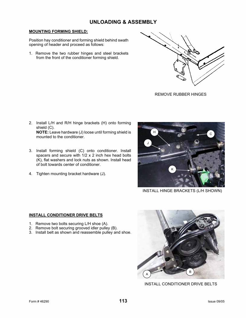
Form # 46290 113 Issue 09/05
UNLOADING & ASSEMBLY MOUNTING FORMING SHIELD: Position hay conditioner and forming shield behind swath opening of header and proceed as follows: 1. Remove the two rubber hinges and steel brackets
from the front of the conditioner forming shield. 2. Install L/H and R/H hinge brackets (H) onto forming
shield (C). NOTE: Leave hardware (J) loose until forming shield is mounted to the conditioner.
3. Install forming shield (C) onto conditioner. Install
spacers and secure with 1/2 x 2 inch hex head bolts (K), flat washers and lock nuts as shown. Install head of bolt towards center of conditioner.
4. Tighten mounting bracket hardware (J). INSTALL CONDITIONER DRIVE BELTS 1. Remove two bolts securing L/H shoe (A). 2. Remove bolt securing grooved idler pulley (B). 3. Install belt as shown and reassemble pulley and shoe.
REMOVE RUBBER HINGES
INSTALL CONDITIONER DRIVE BELTS
A B
INSTALL HINGE BRACKETS (L/H SHOWN)
H
K
J
C

Form # 46290 114 Issue 09/05
UNLOADING & ASSEMBLY HAY CONDITIONER ASSEMBLY:
A 21470 BOLT – round head, square neck, 3/8 NC x 2 inch, gr. 5 B 30228 NUT – smooth flange, 3/8 NC, distorted thread C 18697 NUT – lock, 1/2 NC, distorted thread D 21576 BOLT – hex head, 1/2 NC x 2 inch, gr. 5 E 18599 WASHER – flat, 17/32 I.D. x 1-1/16 inch O.D. F 21863 BOLT – round head, square neck, 3/8 NC x 3/4 inch, gr. 5
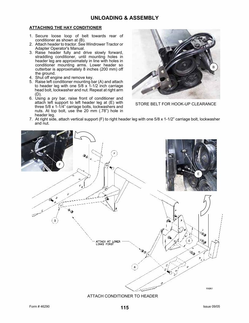
Form # 46290 Issue 09/05 115
UNLOADING & ASSEMBLY ATTACHING THE HAY CONDITIONER 1. Secure loose loop of belt towards rear of
conditioner as shown at (B). 2. Attach header to tractor. See Windrower Tractor or
Adapter Operator's Manual. 3. Raise header fully and drive slowly forward,
straddling conditioner, until mounting holes in header leg are approximately in line with holes in conditioner mounting arms. Lower header so cutterbar is approximately 8 inches (200 mm) off the ground.
4. Shut off engine and remove key. 5. Raise left conditioner mounting bar (A) and attach
to header leg with one 5/8 x 1-1/2 inch carriage head bolt, lockwasher and nut. Repeat at right arm (D).
6. Using a pry bar, raise front of conditioner and attach left support to left header leg at (E) with three 5/8 x 1-1/4” carriage bolts, lockwashers and nuts. At top bolt, use the 20 mm (.78”) hole in header leg.
7. At right side, attach vertical support (F) to right header leg with one 5/8 x 1-1/2” carriage bolt, lockwasher and nut.
STORE BELT FOR HOOK-UP CLEARANCE
B
ATTACH CONDITIONER TO HEADER
F
E

Form # 46290 Issue 09/05 116
UNLOADING & ASSEMBLY ATTACHING THE HAY CONDITIONER (continued) 8. Raise header fully. Stop engine, remove key
and engage header lift cylinder stops. 9. Place a 2 x 4 under the R/H conditioner shoe
as shown at (G). (No block under left side.)
10. Remove header lift cylinder stops and lower conditioner onto block. Shut off engine and remove key.
11. Use the following steps for the appropriate
tractor model:
For 52 Series tractors (24 inch rims only): NOTE: For tractors prior to 52 Series (16 inch rims), see next page.
• Install conditioner lift link (J) at R/H side
as shown. • Install clevis to secure upper end of
adjustable link to lift linkage pin and secure to lower end to chain at R/H conditioner mount.
• Install bolt (M) through chain at R/H conditioner mount.
• Install clevis, lock washer (K) & lynch pin (L) to secure upper end of chain to lift linkage pin.
• With cutterbar set at desired cutting height, adjust turnbuckle link length to 1-1/2 to 2 inch ground clearance to conditioner shoe. Secure jam nut on turnbuckle link.
NOTE: Turnbuckle adjuster pin (N) (shipped with hay conditioner) can be stored in tractor floor board as shown. NOTE: May need to cut chain down to three links for slightly higher conditioner clearance.
BLOCK UNDER R/H SHOE
G
J
M
K L
TURNBUCKLE ADJUSTER PIN STORAGE
N

Form # 46290 Issue 09/05 117
UNLOADING & ASSEMBLY ATTACHING HAY CONDITIONER (continued)
11. cont’d
For Tractors Prior to 52 Series (16 inch rims): • Shorten R/H lift chain to 13 links total
length. • Install clevis, lock washer (K) & lynch pin
(L) to secure upper end of chain to lift linkage pin.
• Secure lower end to R/H conditioner mount with bolt.
• With cutterbar set at desired cutting height, adjust chain length at clevis for 1-1/2 to 2 inch ground clearance to conditioner shoe.
12. Raise header fully. Stop engine, remove key
and engage header lift cylinder stops.
13. Install chain for float spring on pin (L) at left side of conditioner. Connect at the fourth chain link from the spring to start. See Conditioner Float Adjustment under "Operating Variables".
14. Install belts over header pulley (M). NOTE: There must be 5 inches (125 mm)
exposed bolt thread (bottom of pivot to spring plug) on bolt (N) to allow belt installation. Turn bolt (N) counter-clockwise to increase exposed thread length.
15. Align pulleys, then install and tighten three
bushing bolts (J) to secure the pulley position. 16. Tighten belts by turning bolt (N) clockwise until
spring plug contacts bottom of pivot (P). 17. Ensure mounting bracket (B) for clean-out bolts
on lower roll driven pulley is not interfering with belt travel.
Also, ensure clean-out bolts are centered in pulley grooves. Mounting bracket can be adjusted laterally to properly position bolts.
CONNECT FLOAT SPRING & INSTALL BELTS
N P
L
M
J
B
ALIGN BRACKET FOR CLEAN-OUT BOLTS
CHAIN ADJUSTED TO 13 LINKS

Form # 46290 Issue 09/05 118
UNLOADING & ASSEMBLY ATTACHING HAY CONDITIONER (continued)
18. Attach rear supports to forming shield assembly, at the second bolt (P) from each end.
19. Attach top bracket of rear support to rear hole (H)
of the two provided in the tractor floorboard, each side. NOTE: For XX52 & XX52i Windrower Tractors, use the longer top brackets provided. Use the lower hole for mounting the rubber strap.
XX52 & XX52i FORMING SHIELD SUPPORT STRAP

Form # 46290 Issue 09/05 119
UNLOADING & ASSEMBLY ADJUSTMENTS AND CHECKS Perform the final checks and adjustments as listed on the "Pre-Delivery Checklist" (yellow insert) to ensure the machine is field-ready. Use the Operator's Manual for directions. On 21’ to 36’ “combine-configured” headers, place the Operator’s Manual in storage case (A) located under the left end shield.
A
MANUAL STORAGE CASE

Form # 46290 Issue 09/05 120
INDEX A PAGE Assembly..................................................... 100 Auger, Upper Cross (Attachment) ........... 36, 93 B Beans, Edible – Cutting Tips ......................... 87 Bearing Installation........................................ 51 Bleeding Hydraulics..................................... 109 Break-In Period ............................................. 18 C Capacities, Wobble Box ................................ 51 Combine to Windrower Conversion............. 106 Conditioned Windrow Side Delivery System. 97 Cutterbar Poly Wear Strips............................ 93 Cutting Height................................................ 22 D Deck Height Adjustment................................ 71 Deck Shift (Hydraulic Attachment) ................ 91 Deck Split Kit: 36’ Header (Option) ............... 96 Deflectors, Narrow (Attachment) ................... 92 Delivery Opening Width Adjustment ............. 27 Double Windrowing ....................................... 38 Divider Rod Length........................................ 24 Draper Drive Motor Location Guidelines ....... 69 Draper Drive Motors: Moving Out/Inboard .. 106 Draper Idler Roller Positioning ...................... 69 Draper Installation ....................................... 104 Draper Replacement ..................................... 68 Draper Roller Maintenance ........................... 70 Draper Speed ................................................ 27 Draper Tension Adjustment........................... 68 Draper Tracking............................................. 70 E Electrical Schematic ...................................... 59 End Delivery: Manual Shift ............................ 31 End Delivery: Hydraulic Shift......................... 32 End Delivery: Installing Guides ................... 103 F Floating Divider (Attachment)........................ 92 Forming Rods (Attachment) .................... 36, 92 Forming Rods, End Delivery (Attachment).... 92 G Gauge Wheels (Attachment) ................... 22, 94 Gauge Wheel Maintenance........................... 75 Gauge Rollers (Attachment).................... 23, 94 Greasing the Hay Conditioner ....................... 55 Greasing the Header ..................................... 52 Ground Speed ............................................... 25
G (cont’d.) PAGE
Guards, Sickle................................................62 Guards, Stub..................................................63 H
Hay Conditioner: Attaching ............................14 Hay Conditioner Assembly...........................110 Hay Conditioner: Detaching ...........................17 Hay Conditioner: Drive Chain ........................76 Hay Conditioner: Forming Shields ................44 Hay Conditioner: Float ...................................43 Hay Conditioner: Ground Clearance..............42 Hay Conditioner: Roll Intermesh ...................41 Hay Conditioner: Roll Tension Springs ..........41 Hay Conditioner: Roll Timing .........................76 Haying Tips ....................................................45 Header Angle .................................................27 Header Controls .............................................21 Header Flotation.............................................26 Header Lift Cylinder Stops .............................21 Header, Lowering from Shipping Position....100 Hydraulic Hoses and Lines ............................56 Hydraulic Schematic – Combine Apps...........58 Hydraulic Schematic – Reel Lift .....................56 Hydraulic Schematic – Windrower Apps........57 Hydraulic System Safety ................................56 L Lubricants, recommended..............................51
N
Narrow Opening Kit (Attachment) ..................91 M Maintenance Record......................................78 Maintenance Schedule ..................................77 O Operating Variables .......................................22 Options/Attachments......................................91 Owner/Operator Responsibilities ...................13 P Pre-Starting Checks.......................................19 R Raised Sickle Conversion Kits .......................96 Reel Centering in Header ..............................74 Reel Clearance to Cutterbar ..........................72 Reel Drive Chain............................................74 Reel Drive Shaft Removal..............................74 Reel Drive Sprocket Options..........................97

Form # 46290 Issue 09/05 121
INDEX R (cont’d.)
PAGE Reel Fore-Aft Position ................................... 34 Reel "Frown" Adjustment .............................. 72 Reel Height.................................................... 33 Reel Lift Cylinder Bleeding .......................... 109 Reel Pick-Up Finger Pitch ............................. 35 Reel Plastic Finger Installation ...................... 73 Reel Position (Hydraulic Attachment)............ 91 Reel Props..................................................... 21 Reel Speed.................................................... 33 S Safety
Alert Symbol............................................... 6 General Farm ............................................. 8 Header Lift Cylinder Stops ....................... 21 Hydraulic System ..................................... 56 Operating ................................................. 20 Pre-Starting Checks ................................. 19 Reel Props ............................................... 21 Service Procedures.................................. 50 Shut-Down Procedure.............................. 46 Signal Words.............................................. 6 Signs .......................................................... 7 Storage Procedure ................................... 49 Transporting ............................................. 48 Your Responsibilities................................ 13
Serial Number Location................................... 5 Service Procedures ....................................... 50 Shut-Down Procedure ................................... 46 Sickle Drive – Conversion Guidelines ........... 65 Sickle Drive - Conversion Kits ....................... 96 Sickle Drive Belt Tension - Single ................. 65 Sickle Drive Belt Tension - Double................ 66 Sickle Drive Belt Tracking - Double............... 67 Sickle Guards ............................................... 62 Sickle Hold-Downs ........................................ 63 Sickle Head Needle Bearing Installation ....... 61 Sickle Lubrication .......................................... 59 Sickle Removal and Installation ............... 60,61 Sickle Sections .............................................. 60 Sickle Speed - Double Drive ......................... 66 Sickle Storage, Spare.................................... 62 Sickle Timing - Double Drive ......................... 67 Skid Shoes .......................................... 23,94,95 Specifications - Header & Attachments......... 10 Specifications - Torque Values...................... 11 Storage Procedure ........................................ 49 Stub Guard Adjustment ................................. 63 Stub Guard Conversion Kit............................ 93 T Tall Crop Divider (Attachment) ...................... 88 Torque Specifications.................................... 11 Transport, Slow Speed (Option).................... 91 Transporting the Header
on Windrower/Combine............................ 48 Trouble Shooting
Crop Loss at Cutterbar............................. 79
T PAGE
Trouble Shooting (cont’d.) Cutting Components .................................80 Cutting Edible Beans ................................87 Drapers & Decks.......................................84 Hay Conditioner ........................................86 Header ......................................................83 Reel ..........................................................82 Windrow Formation - Grain .......................84 Windrow Formation - Hay .........................86
U Unloading the Header ....................................98 Unplugging the Header & Conditioner ...........47 W Wear Strips & Shoes, plastic (Attachment)....93 Windrow Characteristics ................................39 Windrower to Combine Conversion .............106 Windrowing ....................................................37 Wobble Box ...................................................64

Form # 46290 Issue 09/05
972 Harvest Header Pre-Delivery Checklist HEADER SERIAL NUMBER: Perform these checks and adjustments prior to delivery to your customer. See the Operator's Manual for adjustment details.
CAUTION: Carefully follow the instructions given. Be alert for safety related messages which bring your attention to hazards and unsafe practices.
Check for shipping damage or missing parts. Be sure all shipping dunnage is removed.
Adjust reel clearance from cutterbar to 5/8" [15 mm], both ends (P. 72).
Check reel is centered between header end sheets (P. 74).
Check sickle drive belt(s) tension (P. 65/66).
Check header flotation. (50 to 70 lbs. [220 to 310 N]) (P. 26 & Tractor or Adapter Operator’s Manual)
Check that header is level. (Tractor Operator’s Manual)
Grease all bearings and drive lines (P. 52).
Reposition wobble box breather(s) - (Unless transported upright on trailer) (P. 109).
Check wobble box(es) lube level (P. 64).
Bleed R/H reel lift cylinder (P. 109).
Attach forming rods (if applicable) (P. 36/92).
Check skid shoes are evenly adjusted (P. 23).
Check deck height (draper to cutterbar clearance – 1 mm gap to 1.5 mm draper deflection) (P. 71).
Check draper tension (P. 68).
Check hydraulic hose and wiring harness routing, ensuring adequate clearance with header up or down. Be sure colour coding on hydraulic hoses is matched and that all hydraulic connections are fully engaged.
Run machine at operating speed for 15 minutes, STOP ENGINE and check for belt/idler alignment and
heated bearings. Check sickle sections for discoloration caused by misalignment of components.
Check lights are functional.
On 21’ to 36’ “combine-configured” headers, place Operator’s Manual in storage case under left end shield.
742 HAY CONDITIONER SERIAL NUMBER:
Grease all bearings (P. 55).
Align conditioner drive pulley on header drive shaft (P. 116).
Adjust forming shields to position suitable for conditions (P. 44).
Check conditioner flotation (P. 43). Date Checked: ____ Checked by: