model airplane news constructio n 0v-10...
TRANSCRIPT
MODEL AIRPLANE NEWS
CONSTRUCTION
by Rich Uravitch
40 MODEL AIRPLANE NEWS
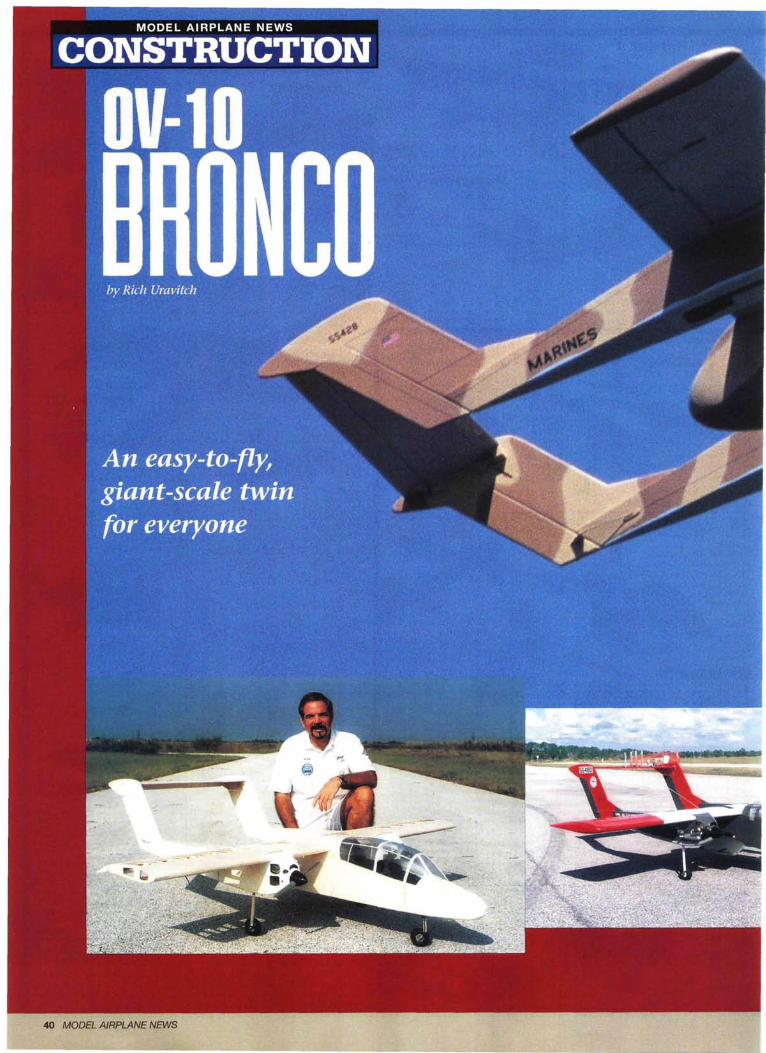
0V-10
BRONCOAn easy-to-flygiant-scale twinfor everyone
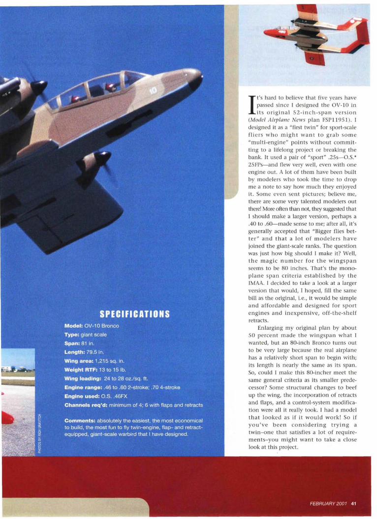
SPECIFICATIONSModel: OV-10 Bronco
Type: giant scale
Span: 81 in.
Length: 79.5 in.
Wing area: 1,215 sq. in.
Weight RTF: 13 to 15 1b.Wing loading: 24 to 28 oz./sq. ft.
Engine range: .46 to .60 2-stroke; .70 4-stroke
Engine used: O.S. .46FX
Channels req'd: minimum of 4; 6 with flaps and retracts
Comments: absolutely the easiest, the most economicalto build, the most fun to fly twin-engine, flap- and retract-equipped, giant-scale warbird that I have designed.
It's hard to believe that five years havepassed since I designed the OV-10 inits original 52-inch-span version
(Model Airplane News plan FSP11951). Idesigned it as a "first twin" for sport-scalefliers who might want to grab some"multi-engine" points without commit-ting to a lifelong project or breaking thebank. It used a pair of "sport" .25s—O.S.*25FPs—and flew very well, even with oneengine out. A lot of them have been builtby modelers who took the time to dropme a note to say how much they enjoyedit. Some even sent pictures; believe me,there are some very talented modelers outthere! More often than not, they suggested thatI should make a larger version, perhaps a.40 to .60—made sense to me; after all, it'sgenerally accepted that "Bigger flies bet-ter" and that a lot of modelers havejoined the giant-scale ranks. The questionwas just how big should I make it? Well,the magic number for the wingspanseems to be 80 inches. That's the mono-plane span criteria established by theIMAA. I decided to take a look at a largerversion that would, I hoped, fill the samebill as the original, i.e., it would be simpleand affordable and designed for sportengines and inexpensive, off-the-shelfretracts.
Enlarging my original plan by about50 percent made the wingspan what Iwanted, but an 80-inch Bronco turns outto be very large because the real airplanehas a relatively short span to begin with;its length is nearly the same as its span.So, could I make this 80-incher meet thesame general criteria as its smaller prede-cessor? Some structural changes to beefup the wing, the incorporation of retractsand flaps, and a control-system modifica-tion were all it really took. I had a modelthat looked as if it would work! So ifyou've been considering trying atwin-one that satisfies a lot of require-ments-you might want to take a closelook at this project.
FEBRUARY 2001 41
OV-10 BRONCO
IT'S A LOT EASIER THAN IT LOOKS ...I can't give you a blow-by-blow descrip-tion of each construction step, but I willtouch on the unique or important issues.If you've built any of the box-style train-ers so prevalent these days, then youalready have most of the building skillsrequired to frame up a Bronco. It basicallyconsists of building three box-shapedfuselages and a constant-chord wing withno dihedral. This allows you to build thewing directly over the plan on a flat sur-face; just make certain the surface is flat. Idrew the wing in two panels so that Icould build them separately and then jointhem. To begin construction, I usually pinall the lower sheeting into place over theplan and then add the lower capstrips andthe lower spars, followed by the ribs. Inaddition to providing a slightly more rigidstructure, this method reduces the lower-surface sanding required to blend thesheeting with the capstrips.
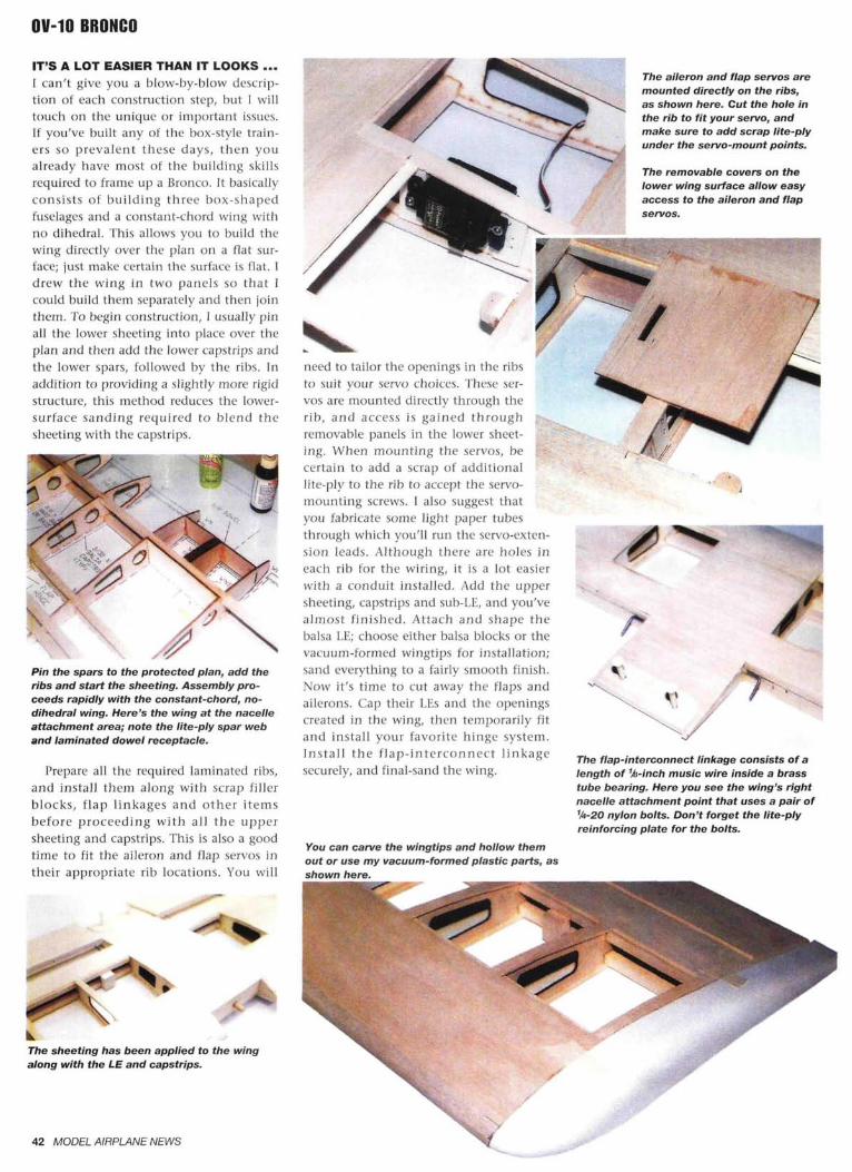
Pin the spars to the protected plan, add theribs and start the sheeting. Assembly pro-ceeds rapidly with the constant-chord, no-dihedral wing. Here's the wing at the nacelleattachment area; note the lite-ply spar weband laminated dowel receptacle.
Prepare all the required laminated ribs,and install them along with scrap fillerblocks, flap linkages and other itemsbefore proceeding with all the uppersheeting and capstrips. This is also a goodtime to fit the aileron and flap servos intheir appropriate rib locations. You will
need to tailor the openings in the ribsto suit your servo choices. These ser-vos are mounted directly through therib, and access is gained throughremovable panels in the lower sheet-ing. When mounting the servos, becertain to add a scrap of additionallite-ply to the rib to accept the servo-mounting screws. 1 also suggest thatyou fabricate some light paper tubesthrough which you'll run the servo-exten-sion leads. Although there are holes ineach rib for the wiring, it is a lot easierwith a conduit installed. Add the uppersheeting, capstrips and sub-LE, and you'vealmost finished. Attach and shape thebalsa LE; choose either balsa blocks or thevacuum-formed wingtips for installation;sand everything to a fairly smooth finish.Now it's time to cut away the flaps andailerons. Cap their LEs and the openingscreated in the wing, then temporarily fitand install your favorite hinge system.Install the flap-interconnect linkagesecurely, and final-sand the wing.
You can carve the wingtips and hollow themout or use my vacuum-formed plastic parts, asshown here.
The aileron and flap servos aremounted directly on the ribs,as shown here. Cut the hole inthe rib to fit your servo, andmake sure to add scrap lite-plyunder the servo-mount points.
The removable covers on thelower wing surface allow easyaccess to the aileron and flapservos.
/ ~"
The flap-interconnect linkage consists of alength of %-inch music wire inside a brasstube bearing. Here you see the wing's rightnacelle attachment point that uses a pair ofV4-20 nylon bolts. Don't forget the lite-plyreinforcing plate for the bolts.
The sheeting has been applied to the wingalong with the LE and capstrips.
42 MODEL AIRPLANE NEWS
FUSELAGE AND NACELLESThe fuselage and nacelles are about as easyto assemble as they come; they consist oflite-ply sides and bulkheads plus somelongerons for strength and to allow you toround the sharp edges somewhat. Notethat the fuselage formers (bulkheads) l-'4through F7 are actually assembled from1/4x3/4-inch lite-ply or basswood strips. Theremaining bulkheads are cut from 1/6-inchlite-ply. When you install the bulkheads,make certain that they are square and thatyou haven't built any twist into theassemblies. The only bulkhead thatshould not be square is the right-handnacelle firewall. It should be installed toprovide 3 degrees of right thrust to helpwith those rare engine-outs.
Before you add the upper and lower 542-inch balsa sheeting to the nacelles, installthe internal portion of the elevator andrudder pushrod linkages, which may be
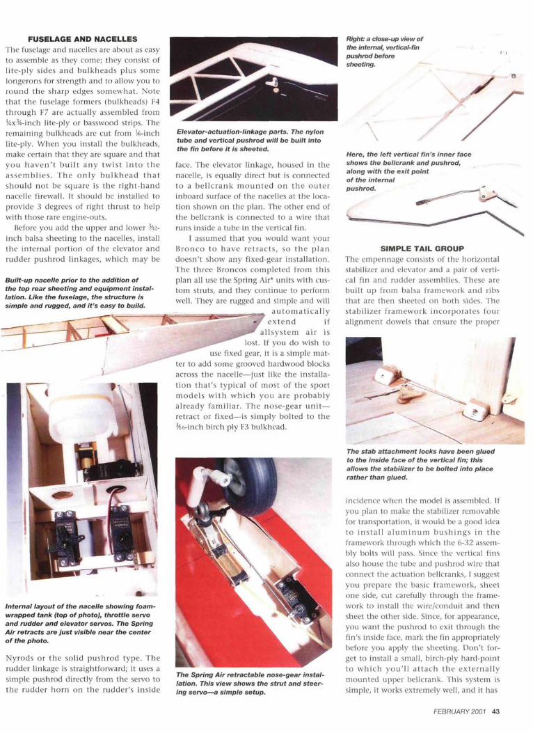
Built-up nacelle prior to the addition ofthe top rear sheeting and equipment instal-lation. Like the fuselage, the structure issimple and rugged, and it's easy to build.
Right: a close-up view ofthe internal, vertical-finpushrod beforesheeting.
Elevator-actuation-linkage parts. The nylontube and vertical pushrod will be built intothe fin before it is sheeted.
face. The elevator linkage, housed in thenacelle, is equally direct but is connectedto a bellcrank mounted on the outerinboard surface of the nacelles at the loca-tion shown on the plan. The other end ofthe bellcrank is connected to a wire thatruns inside a tube in the vertical fin.
I assumed that you would want yourBronco to have retracts, so the plandoesn't show any fixed-gear installation.The three Broncos completed from thisplan all use the Spring Air* units with cus-tom struts, and they continue to performwell. They are rugged and simple and will
automaticallyextend if
allsystem air islost. If you do wish to
use fixed gear, it is a simple mat-ter to add some grooved hardwood blocksacross the nacelle—just like the installa-tion that's typical of most of the sportmodels with which you are probablyalready familiar. The nose-gear unit—retract or fixed—is simply bolted to theMh-inch birch ply F3 bulkhead.
Internal layout of the nacelle showing foam-wrapped tank (top of photo), throttle servoand rudder and elevator servos. The SpringAir retracts are just visible near the centerof the photo.
Nyrods or the solid pushrod type. Therudder linkage is straightforward; it uses asimple pushrod directly from the servo tothe rudder horn on the rudder's inside
Here, the left vertical fin's inner faceshows the bellcrank and pushrod,along with the exit pointof the internalpushrod.
SIMPLE TAIL GROUPThe empennage consists of the horizontalstabilizer and elevator and a pair of verti-cal fin and rudder assemblies. These arebuilt up from balsa framework and ribsthat are then sheeted on both sides. Thestabilizer framework incorporates fouralignment dowels that ensure the proper
The Spring Air retractable nose-gear instal-lation. This view shows the strut and steer-ing servo—a simple setup.
The stab attachment locks have been gluedto the inside face of the vertical fin; thisallows the stabilizer to be bolted into placerather than glued.
incidence when the model is assembled. Ifyou plan to make the stabilizer removablefor transportation, it would be a good ideato install aluminum bushings in theframework through which the 6-32 assem-bly bolts will pass. Since the vertical finsalso house the tube and pushrod wire thatconnect the actuation bellcranks, I suggestyou prepare the basic framework, sheetone side, cut carefully through the frame-work to install the wire/conduit and thensheet the other side. Since, for appearance,you want the pushrod to exit through thefin's inside face, mark the fin appropriatelybefore you apply the sheeting. Don't for-get to install a small, birch-ply hard-pointto which you'll attach the externallymounted upper bellcrank. This system issimple, it works extremely well, and it has
FEBRUARY 2001 43
OV-10 BRONCO
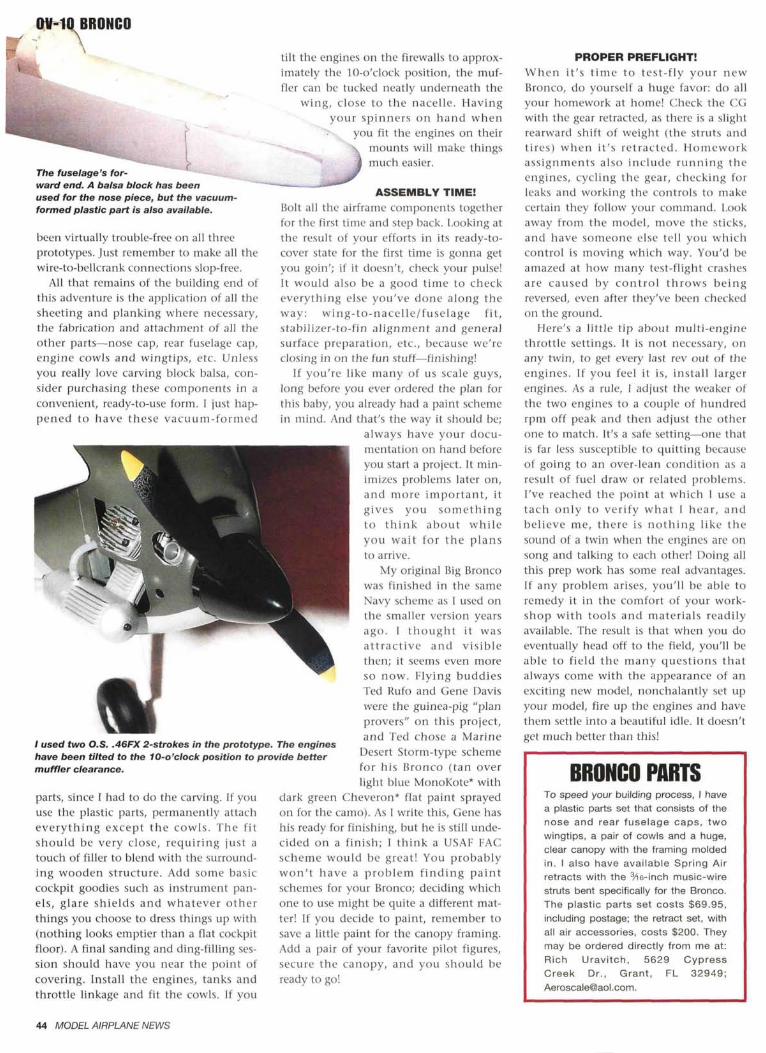
The fuselage's for-ward end. A balsa block has beenused for the nose piece, but the vacuum-formed plastic part is also available.
been virtually trouble-free on all threeprototypes. Just remember to make all thewire-to-bellcrank connections slop-free.
All that remains of the building end ofthis adventure is the application of all thesheeting and planking where necessary,the fabrication and attachment of all theother parts—nose cap, rear fuselage cap,engine cowls and wingtips, etc. Unlessyou really love carving block balsa, con-sider purchasing these components in aconvenient, ready-to-use form. I just hap-pened to have these vacuum-formed
/ used two O.S. .46FX 2-strokes in the prototype. The engineshave been tilted to the 10-o'clock position to provide bettermuffler clearance.
parts, since I had to do the carving. If youuse the plastic parts, permanently attacheverything except the cowls. The fitshould be very close, requiring just atouch of filler to blend with the surround-ing wooden structure. Add some basiccockpit goodies such as instrument pan-els, glare shields and whatever otherthings you choose to dress things up with(nothing looks emptier than a flat cockpitfloor). A final sanding and ding-filling ses-sion should have you near the point ofcovering. Install the engines, tanks andthrottle linkage and fit the cowls. If you
tilt the engines on the firewalls to approx-imately the 10-o'clock position, the muf-fler can be tucked neatly underneath the
wing, close to the nacelle. Havingyour spinners on hand when
you fit the engines on theirmounts will make thingsmuch easier.
ASSEMBLY TIME!Bolt all the airframc components togetherfor the first time and step back. Looking atthe result of your efforts in its ready-to-cover state for the first time is gonna getyou goin'; if it doesn't, check your pulse!It would also be a good time to checkeverything else you've done along theway: wing-to-nacelle/fuselage fit,stabilizer-to-fin alignment and generalsurface preparation, etc., because we'reclosing in on the fun stuff—finishing!
If you're like many of us scale guys,long before you ever ordered the plan forthis baby, you already had a paint schemein mind. And that's the way it should be;
always have your docu-mentation on hand beforeyou start a project. It min-imizes problems later on,and more important, itgives you somethingto think about whileyou wait for the plansto arrive.
My original Big Broncowas finished in the sameNavy scheme as I used onthe smaller version yearsago. I thought it wasattractive and visiblethen; it seems even moreso now. Flying buddiesTed Rufo and Gene Daviswere the guinea-pig "planprovers" on this project,and Ted chose a Marine
Desert Storm-type schemefor his Bronco (tan overlight blue MonoKote* with
dark green Cheveron* flat paint sprayedon for the camo). As I write this, Gene hashis ready for finishing, but he is still unde-cided on a finish; I think a USAF FACscheme would be great! You probablywon't have a problem finding paintschemes for your Bronco; deciding whichone to use might be quite a different mat-ter! If you decide to paint, remember tosave a little paint for the canopy framing.Add a pair of your favorite pilot figures,secure the canopy, and you should beready to go!
PROPER PREFLIGHT!When it's time to test-fly your newBronco, do yourself a huge favor: do allyour homework at home! Check the CGwith the gear retracted, as there is a slightrearward shift of weight (the struts andtires) when it's retracted. Homeworkassignments also include running theengines, cycling the gear, checking forleaks and working the controls to makecertain they follow your command. Lookaway from the model, move the sticks,and have someone else tell you whichcontrol is moving which way. You'd beamazed at how many test-flight crashesare caused by control throws beingreversed, even after they've been checkedon the ground.
Here's a little tip about multi-enginethrottle settings. It is not necessary, onany twin, to get every last rev out of theengines. If you feel it is, install largerengines. As a rule, I adjust the weaker ofthe two engines to a couple of hundredrpm off peak and then adjust the otherone to match. It's a safe setting—one thatis far less susceptible to quitting becauseof going to an over-lean condition as aresult of fuel draw or related problems.I've reached the point at which 1 use atach only to verify what I hear, andbelieve me, there is nothing like thesound of a twin when the engines are onsong and talking to each other! Doing allthis prep work has some real advantages.If any problem arises, you'll be able toremedy it in the comfort of your work-shop with tools and materials readilyavailable. The result is that when you doeventually head off to the field, you'll beable to field the many questions thatalways come with the appearance of anexciting new model, nonchalantly set upyour model, fire up the engines and havethem settle into a beautiful idle. It doesn'tget much better than this!
BRONCO PARTSTo speed your building process, I havea plastic parts set that consists of thenose and rear fuselage caps, twowingtips, a pair of cowls and a huge,clear canopy with the framing moldedin. I also have available Spring Airretracts with the 3/16-inch music-wirestruts bent specifically for the Bronco.The plastic parts set costs $69.95,including postage; the retract set, withall air accessories, costs $200. Theymay be ordered directly from me at:Rich Uravitch, 5629 CypressCreek Dr., Grant, FL 32949;Aeroscale@aol .com.
44 MODEL AIRPLANE NEWS
OV-10 BRONCO
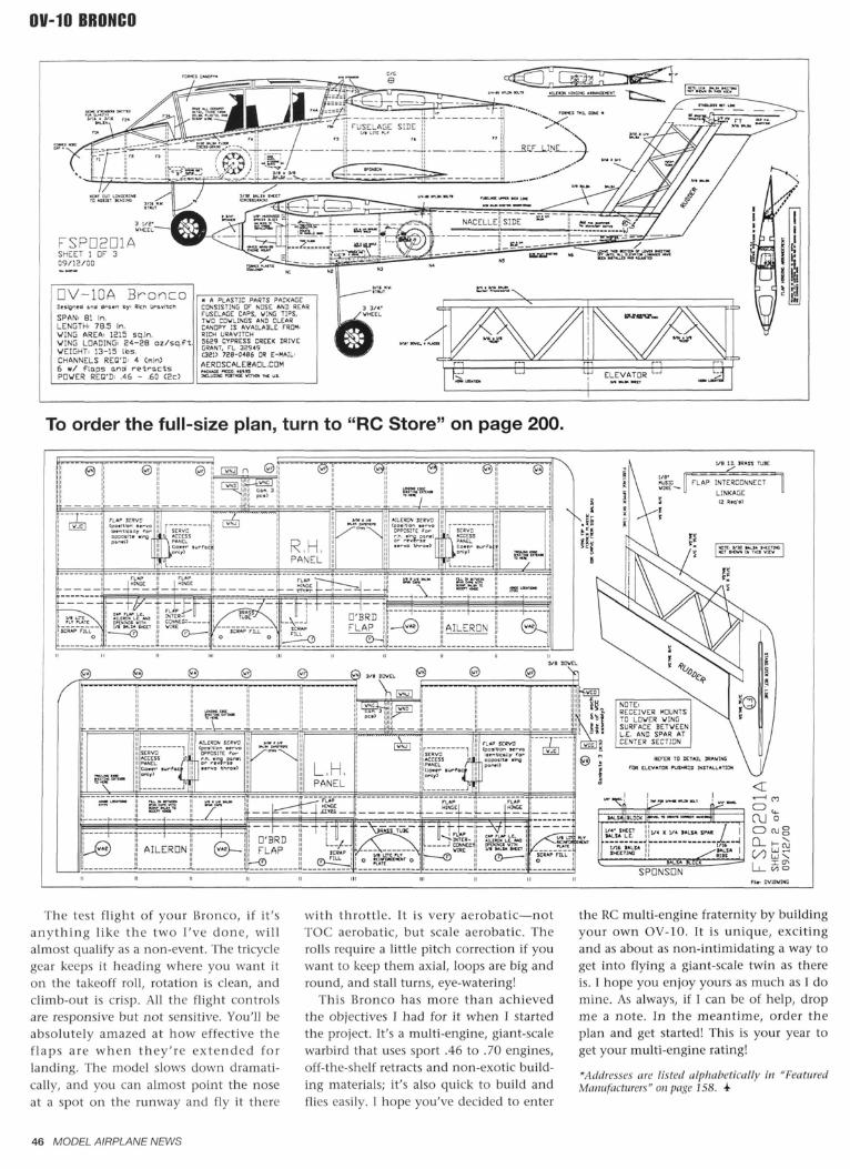
FSPD2D1ASHEET 1 OF 309/12/00
DV-10A BroncoDesigned and drawn By Rich urovttchSPAN. Bl In.LENGTH. 78.5 In.WING AREA. 1215 sq.in.WING LOADING. 34-28 oz/sq. f tWEIGHT. 13-15 lbs.CHANNELS REQ'D- 4 <nln)6 w/ flaps and r e t r a c t sPOWER REQ'D. .46 - .60 <2c3
« * PLASTIC PORTS PACKAGECONSISTING DF NDSE AND REARFUSELAGE CAPS. WING TIPS,TVD COWLINGS AND CLEARCANDPV IS AVAILABLE FROM'RICH URAVITCH5629 CYPRESS CREEK DRIVEGRANT, FL 32949(321) 72B -0486 DR E-MAIL
AERDSCALEeADL.COMMQ.UBHC KBT WITHIN TIME
To order the full-size plan, turn to "RC Store" on page 200.
TO LOWER WINGSURFACE BETWEENL.E. AND SPAR ATCENTER SECTION
BALSA BLOCK
I/4 SHEETBALSA L. E.
1/16 BALSASHEETING
1/4 X 1/4 BALSA SPAR
BALSA
BALSA BLOCK
—
SPDNSDN
CD ai'
ON
The test flight of your Bronco, if it'sanything like the two I've done, willalmost qualify as a non-event. The tricyclegear keeps it heading where you want iton the takeoff roll, rotation is clean, andclimb-out is crisp. All the flight controlsare responsive but not sensitive. You'll beabsolutely amazed at how effective theflaps are when they're extended forlanding. The model slows down dramati-cally, and you can almost point the noseat a spot on the runway and fly it there
with throttle. It is very aerobatic—notTOC aerobatic, but scale aerobatic. Therolls require a little pitch correction if youwant to keep them axial, loops are big andround, and stall turns, eye-watering!
This Bronco has more than achievedthe objectives I had for it when I startedthe project. It's a multi-engine, giant-scalewarbird that uses sport .46 to .70 engines,off-the-shelf retracts and non-exotic build-ing materials; it's also quick to build andflies easily. 1 hope you've decided to enter
the RC multi-engine fraternity by buildingyour own OV-10. It is unique, excitingand as about as non-intimidating a way toget into flying a giant-scale twin as thereis. I hope you enjoy yours as much as I domine. As always, if I can be of help, dropme a note. In the meantime, order theplan and get started! This is your year toget your multi-engine rating!
* Addresses arc listed alphabetically in "FeaturedManufacturers" on page 158.
46 MODEL AIRPLANE NEWS