model based engineering - robot car
TRANSCRIPT
MODEL BASED ENGINEERING -
ROBOT CAR
Mika Pesu
Master’s thesis
Septemper 2015
Master's Degree Programme
in Information Technology
ABSTRACT
Tampereen ammattikorkeakoulu
Tampere University of Applied Sciences
Master`s Degree Programme in Information Technology
AUTHOR: MIKA PESU
Model based engineering - Robot car
Master's thesis 43 pages
Septemper 2015
Purpose of the project was to research ways of implementing a framework to model
robot using activity and component diagrams. Project is constructed in phases, phase 1
included building a suitable modelling framework and platform that runs created dia-
grams. Future phases will expand support for more robot specific features.
Modelling framework goals are that the actual robot modeller does not need to know
any programming language and does not need to compile created activities to platform
code. Modelling framework only supports activity and component diagrams on first
phase.
Modelled robot goals are that created activity diagrams were able to run on robot hard-
ware. Robot is used on constructed track and robot is able to move through track and
detect distances on constructed walls and based on distances either turn right or left.
Key words: model based engineering, robot car, UML, Robotics
3
CONTENTS
1 INTRODUCTION ....................................................................................................... 6
2 ROBOTICS ................................................................................................................. 7
2.1 Industrial robots ................................................................................................... 7
2.2 Robots in research ................................................................................................ 8
2.3 Military robots ..................................................................................................... 9
2.4 Robots in education ........................................................................................... 10
2.5 Future ................................................................................................................. 11
2.6 Theory ................................................................................................................ 12
2.7 Model based engineering ................................................................................... 13
3 MODELLING FRAMEWORK ................................................................................ 15
3.1 Goals .................................................................................................................. 15
3.2 Architecture ....................................................................................................... 15
3.3 Desktop application ........................................................................................... 17
3.3.1 Component diagram ................................................................................ 17
3.3.2 Activity diagram...................................................................................... 19
3.3.3 Swimlane ................................................................................................. 19
3.3.4 Activity start ............................................................................................ 20
3.3.5 Activity end ............................................................................................. 20
3.3.6 Action ...................................................................................................... 21
3.3.7 Datastore ................................................................................................. 21
3.3.8 Decision................................................................................................... 22
3.3.9 Fork and join ........................................................................................... 22
3.4 Platform ............................................................................................................. 23
3.5 Model generation ............................................................................................... 24
4 PROJECT .................................................................................................................. 27
4.1 Goals .................................................................................................................. 27
4.2 Robot .................................................................................................................. 27
4.2.1 Chassis and motors .................................................................................. 27
4.2.2 Motor controller ...................................................................................... 28
4.2.3 Power system .......................................................................................... 28
4.2.4 Raspberry PI ............................................................................................ 28
4.2.5 Servo ....................................................................................................... 29
4.2.6 Ultrasonic sensor ..................................................................................... 30
4.2.7 Wiring ..................................................................................................... 32
4.3 Software ............................................................................................................. 34
4.3.1 Component diagram ................................................................................ 34
4
4.3.2 Motor controller ...................................................................................... 35
4.3.3 Sensor handling ....................................................................................... 37
4.3.4 Main program .......................................................................................... 38
4.3.5 Deployment ............................................................................................. 39
5 CONCLUSIONS AND FUTURE WORK ................................................................ 40
5.1 ROS Support ...................................................................................................... 40
5.2 Debugging support ............................................................................................. 40
5.3 Plugin loading .................................................................................................... 40
5.4 Code generation ................................................................................................. 41
5.5 Distance measurement using stereo vision ........................................................ 41
REFERENCES ................................................................................................................ 42
5
ABBREVIATIONS AND TERMS
ROS Robot operating system
MDE Model-driven engineering
MDA Model-driven architecture
OMG Object management group
UML Unified modelling language
GPIO General purpose I/O
UART Universal Asynchronous Receiver Transmitter
I2C Inter-Integrated Circuit
SPI Serial Peripheral Interface
PWM Pulse-width modulation
UI User Interface
API Application Programming Interface
AI Artifical Intelligency
6
1 INTRODUCTION
The aim of this work is to provide one approach for model based engineering when cre-
ating software for a specific application domain.
Project is constructed in phases, phase 1 goal is to build modelling framework in proof
of concept phase where robot can be modelled and executed in platform. Modelling
framework goal is to have ability to model robot using component and activity dia-
grams. Modelled robot goal is to create activity diagrams to allow movement through
constructed track and by measuring distances know when to turn left or right. This the-
sis is targetted for phase 1 construction.
Phase 2 will introduce ROS (Robot operating system) support and extend component
library by using ROS device drivers. Phase 2 will also introduce debugging and code
generation support.
7
2 ROBOTICS
Robotics is multidisciplinary field containing mechanical engineering, electrical engi-
neering and computer science aspects that deals with the design, construction, operation
and applications. Robotics also contain computer systems for control, sensor feedback
and information processing. (Robotics, Wikipedia, 2015)
Robot is mechanical device that is programmed to perform tasks and interact with its
environment without the aid of human interaction. Science and technology behind the
design, manufacturing and applications of robots is robotics. (Introduction to robotics,
VEX Robotics, 2015)
Robots can perform multiple different tasks, most notable robotics areas are:
Industrial
Research
Military
Education
2.1 Industrial robots
Industrial robots are defined as controllable, reprogrammable, multipurpose program-
mable manipulator working in three or more axes. Industrial robots are defined in ISO
8373. (Industrial robot, Wikipedia, 2015)
Industrial robots work for example in manufacturing carring out repetive actions, as-
sembly line, welding, painting or as automated packaging in factory. (Industrial robot,
Wikipedia, 2015)

8
Picture 1. Assembly line robot (Assembly robot, Metalworking magazine, 2015)
2.2 Robots in research
Robots in research is used to perform tasks or reach locations that would be impossible
for humans. These robots work on most dangerous and challenging environments there
is, locations that are found beyond the Earth. NASA has used for decades probes,
landers and rovers with robotic characterictics to study outer space and planets in our
solar system. (Introduction to robotics, VEX Robotics, 2015).
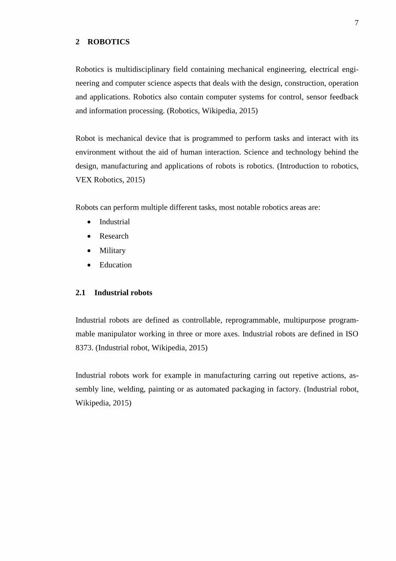
Mars rover is one of the robots in research that is able to carry out tasks in Mars to de-
tect if life ever arose on the planet, study climate and geology on Mars. Rover is also
preparation for human exploration of Mars. (Mars rover, Wikipedia, 2015)
9
PICTURE 2. Mars rover Curiosity (Mars rover, Wikipedia, 2015)
2.3 Military robots
Fully autonomous robots in military are still in research phase but there are multiple
task operated and remote controlled robots. Task operated robots are semi-autonomous
robots, they are given an task and robot executes it. Remote controlled robots have op-
erator that controls the robot remotely. Militaries through out the world are increasingly
researching ways to introduce more autonomous robots in warfare. (Military robot,
Wikipedia, 2015)
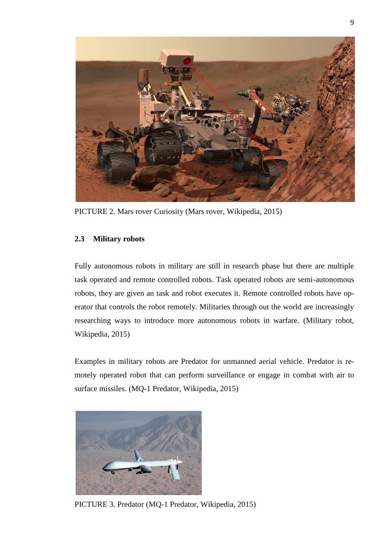
Examples in military robots are Predator for unmanned aerial vehicle. Predator is re-
motely operated robot that can perform surveillance or engage in combat with air to
surface missiles. (MQ-1 Predator, Wikipedia, 2015)
PICTURE 3. Predator (MQ-1 Predator, Wikipedia, 2015)
10
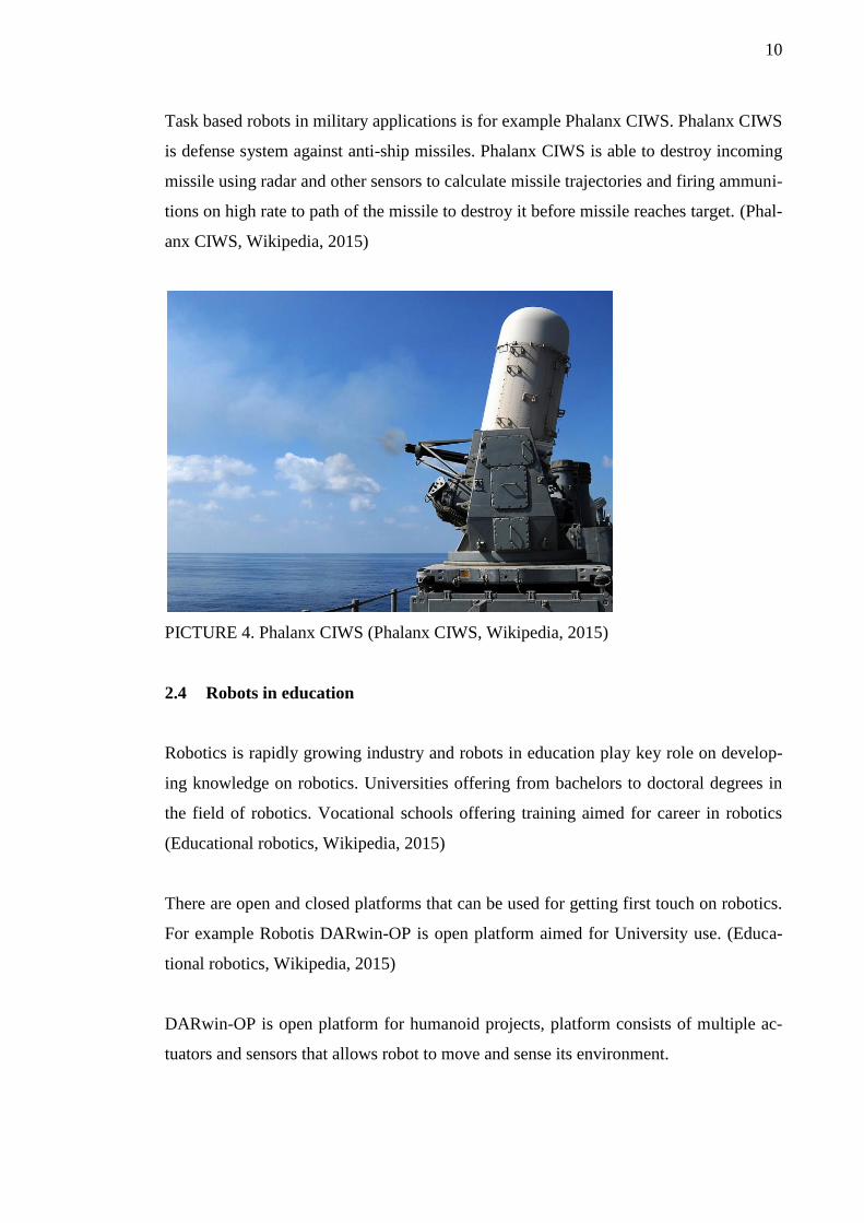
Task based robots in military applications is for example Phalanx CIWS. Phalanx CIWS
is defense system against anti-ship missiles. Phalanx CIWS is able to destroy incoming
missile using radar and other sensors to calculate missile trajectories and firing ammuni-
tions on high rate to path of the missile to destroy it before missile reaches target. (Phal-
anx CIWS, Wikipedia, 2015)
PICTURE 4. Phalanx CIWS (Phalanx CIWS, Wikipedia, 2015)
2.4 Robots in education
Robotics is rapidly growing industry and robots in education play key role on develop-
ing knowledge on robotics. Universities offering from bachelors to doctoral degrees in
the field of robotics. Vocational schools offering training aimed for career in robotics
(Educational robotics, Wikipedia, 2015)
There are open and closed platforms that can be used for getting first touch on robotics.
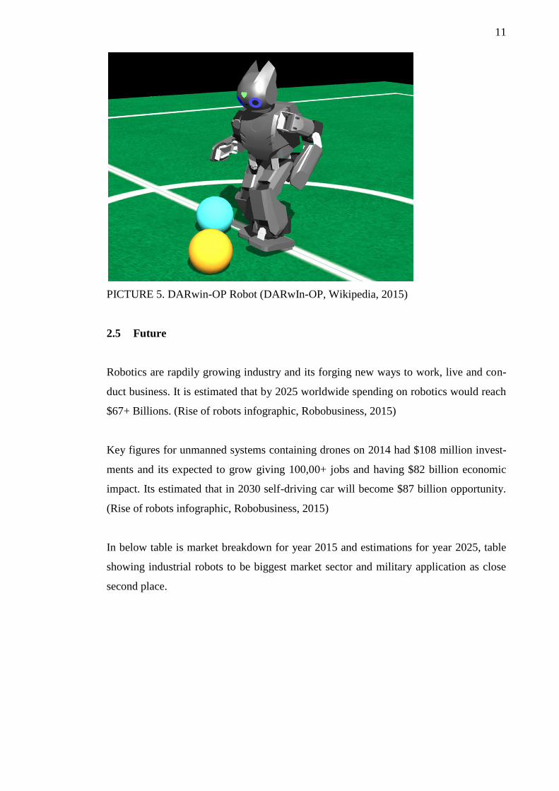
For example Robotis DARwin-OP is open platform aimed for University use. (Educa-
tional robotics, Wikipedia, 2015)
DARwin-OP is open platform for humanoid projects, platform consists of multiple ac-
tuators and sensors that allows robot to move and sense its environment.
11
PICTURE 5. DARwin-OP Robot (DARwIn-OP, Wikipedia, 2015)
2.5 Future
Robotics are rapdily growing industry and its forging new ways to work, live and con-
duct business. It is estimated that by 2025 worldwide spending on robotics would reach
$67+ Billions. (Rise of robots infographic, Robobusiness, 2015)
Key figures for unmanned systems containing drones on 2014 had $108 million invest-
ments and its expected to grow giving 100,00+ jobs and having $82 billion economic
impact. Its estimated that in 2030 self-driving car will become $87 billion opportunity.
(Rise of robots infographic, Robobusiness, 2015)
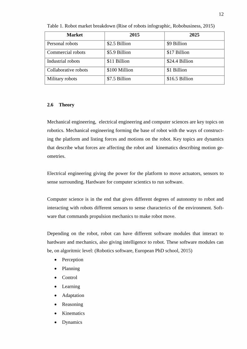
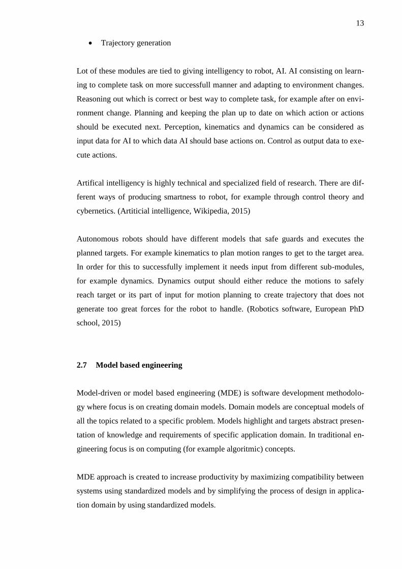
In below table is market breakdown for year 2015 and estimations for year 2025, table
showing industrial robots to be biggest market sector and military application as close
second place.
12
Table 1. Robot market breakdown (Rise of robots infographic, Robobusiness, 2015)
Market 2015 2025
Personal robots $2.5 Billion $9 Billion
Commercial robots $5.9 Billion $17 Billion
Industrial robots $11 Billion $24.4 Billion
Collaborative robots $100 Million $1 Billion
Military robots $7.5 Billion $16.5 Billion
2.6 Theory
Mechanical engineering, electrical engineering and computer sciences are key topics on
robotics. Mechanical engineering forming the base of robot with the ways of construct-
ing the platform and listing forces and motions on the robot. Key topics are dynamics
that describe what forces are affecting the robot and kinematics describing motion ge-
ometries.
Electrical engineering giving the power for the platform to move actuators, sensors to
sense surrounding. Hardware for computer scientics to run software.
Computer science is in the end that gives different degrees of autonomy to robot and
interacting with robots different sensors to sense characterics of the environment. Soft-
ware that commands propulsion mechanics to make robot move.
Depending on the robot, robot can have different software modules that interact to
hardware and mechanics, also giving intelligence to robot. These software modules can
be, on algoritmic level: (Robotics software, European PhD school, 2015)
Perception
Planning
Control
Learning
Adaptation
Reasoning
Kinematics
Dynamics
13
Trajectory generation
Lot of these modules are tied to giving intelligency to robot, AI. AI consisting on learn-
ing to complete task on more successfull manner and adapting to environment changes.
Reasoning out which is correct or best way to complete task, for example after on envi-
ronment change. Planning and keeping the plan up to date on which action or actions
should be executed next. Perception, kinematics and dynamics can be considered as
input data for AI to which data AI should base actions on. Control as output data to exe-
cute actions.
Artifical intelligency is highly technical and specialized field of research. There are dif-
ferent ways of producing smartness to robot, for example through control theory and
cybernetics. (Artiticial intelligence, Wikipedia, 2015)
Autonomous robots should have different models that safe guards and executes the
planned targets. For example kinematics to plan motion ranges to get to the target area.
In order for this to successfully implement it needs input from different sub-modules,
for example dynamics. Dynamics output should either reduce the motions to safely
reach target or its part of input for motion planning to create trajectory that does not
generate too great forces for the robot to handle. (Robotics software, European PhD
school, 2015)
2.7 Model based engineering
Model-driven or model based engineering (MDE) is software development methodolo-
gy where focus is on creating domain models. Domain models are conceptual models of
all the topics related to a specific problem. Models highlight and targets abstract presen-
tation of knowledge and requirements of specific application domain. In traditional en-
gineering focus is on computing (for example algoritmic) concepts.
MDE approach is created to increase productivity by maximizing compatibility between
systems using standardized models and by simplifying the process of design in applica-
tion domain by using standardized models.
14
Better known MDE initiatives are the Object Management Group (OMG) intiative for
model-driven architecture (MDA), which is registered trademark of OMG. Other initia-
tive is eclipse ecosystem of programming and modelling tools, Eclipse Modelling
Framework.
15
3 MODELLING FRAMEWORK
3.1 Goals
Modelling framework goal is to build framework that allows to design UML notated
model and execute it on selected platform. UML modelling supports only component
and activity diagrams on the first phase. Designer framework allows to draw model and
generate binary file that contains only UML diagram data, no code generation from
UML model is supported. Modelling framework only supports few selected hardware
components. These are built-in to framework support.
3.2 Architecture
Architecture selected for program was component based. This allows implementation of
each set of component using standard interface. Every component publishes own fea-
tures through Qt meta object system using properties.
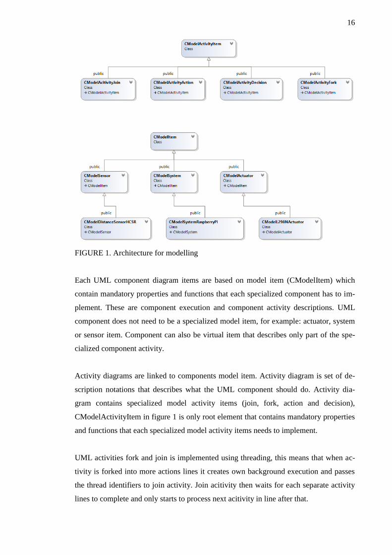
Architecture is split into two parts, first part is used to define UML component diagram
(CModelItem) and second part to define UML activity diagram (CModelActivityItem).
Class hierarcy for UML modelling can be seen from figure 1.
16
FIGURE 1. Architecture for modelling
Each UML component diagram items are based on model item (CModelItem) which
contain mandatory properties and functions that each specialized component has to im-
plement. These are component execution and component activity descriptions. UML
component does not need to be a specialized model item, for example: actuator, system
or sensor item. Component can also be virtual item that describes only part of the spe-
cialized component activity.
Activity diagrams are linked to components model item. Activity diagram is set of de-
scription notations that describes what the UML component should do. Activity dia-
gram contains specialized model activity items (join, fork, action and decision),
CModelActivityItem in figure 1 is only root element that contains mandatory properties
and functions that each specialized model activity items needs to implement.
UML activities fork and join is implemented using threading, this means that when ac-
tivity is forked into more actions lines it creates own background execution and passes
the thread identifiers to join activity. Join acitivity then waits for each separate activity
lines to complete and only starts to process next acitivity in line after that.
17
3.3 Desktop application
Desktop application is built using C++ and utilizing Qt framework for cross-platform
support. User interface is built partly using Qt Q
Widgets for menu and toolbar. Qt QML is used for actual UML area.
QWidget is Qt frameworks old method of building user interfaces, widgets are class
based presentation of user interface. QML is declarative language to describe user inter-
faces. QML is JSON-like syntax with JavaScript support for dynamic binding.
Application is divided to two parts, component and activity diagrams editor.
3.3.1 Component diagram
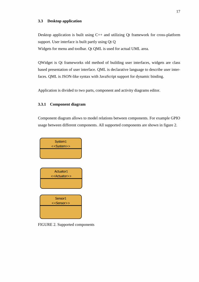
Component diagram allows to model relations between components. For example GPIO
usage between different components. All supported components are shown in figure 2.
FIGURE 2. Supported components
18
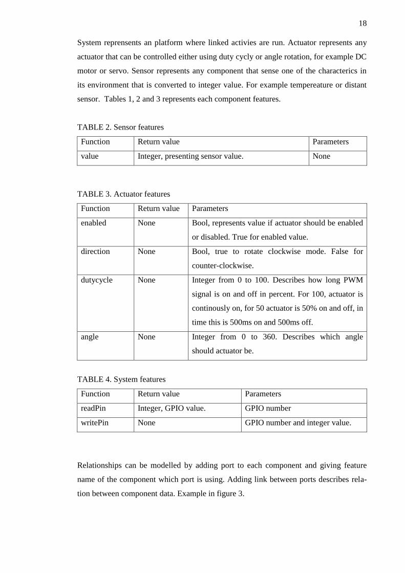
System reprensents an platform where linked activies are run. Actuator represents any
actuator that can be controlled either using duty cycly or angle rotation, for example DC
motor or servo. Sensor represents any component that sense one of the characterics in
its environment that is converted to integer value. For example tempereature or distant
sensor. Tables 1, 2 and 3 represents each component features.
TABLE 2. Sensor features
Function Return value Parameters
value Integer, presenting sensor value. None
TABLE 3. Actuator features
Function Return value Parameters
enabled None Bool, represents value if actuator should be enabled
or disabled. True for enabled value.
direction None Bool, true to rotate clockwise mode. False for
counter-clockwise.
dutycycle None Integer from 0 to 100. Describes how long PWM
signal is on and off in percent. For 100, actuator is
continously on, for 50 actuator is 50% on and off, in
time this is 500ms on and 500ms off.
angle None Integer from 0 to 360. Describes which angle
should actuator be.
TABLE 4. System features
Function Return value Parameters
readPin Integer, GPIO value. GPIO number
writePin None GPIO number and integer value.
Relationships can be modelled by adding port to each component and giving feature
name of the component which port is using. Adding link between ports describes rela-
tion between component data. Example in figure 3.
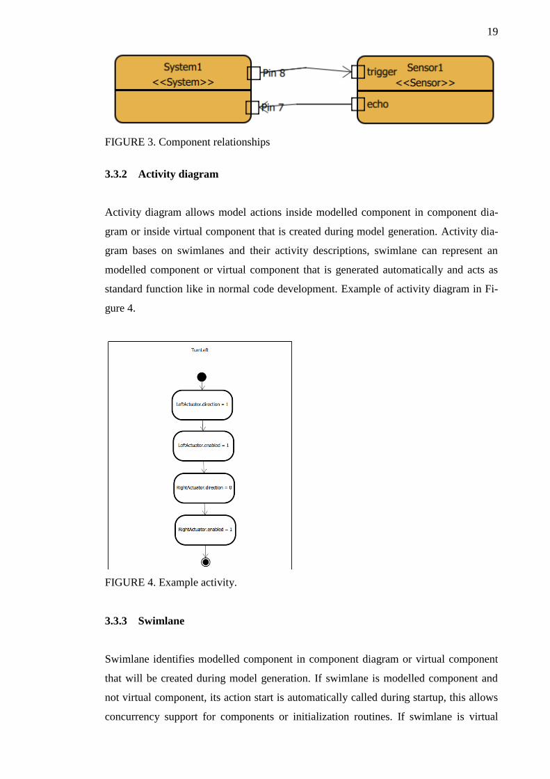
19
FIGURE 3. Component relationships
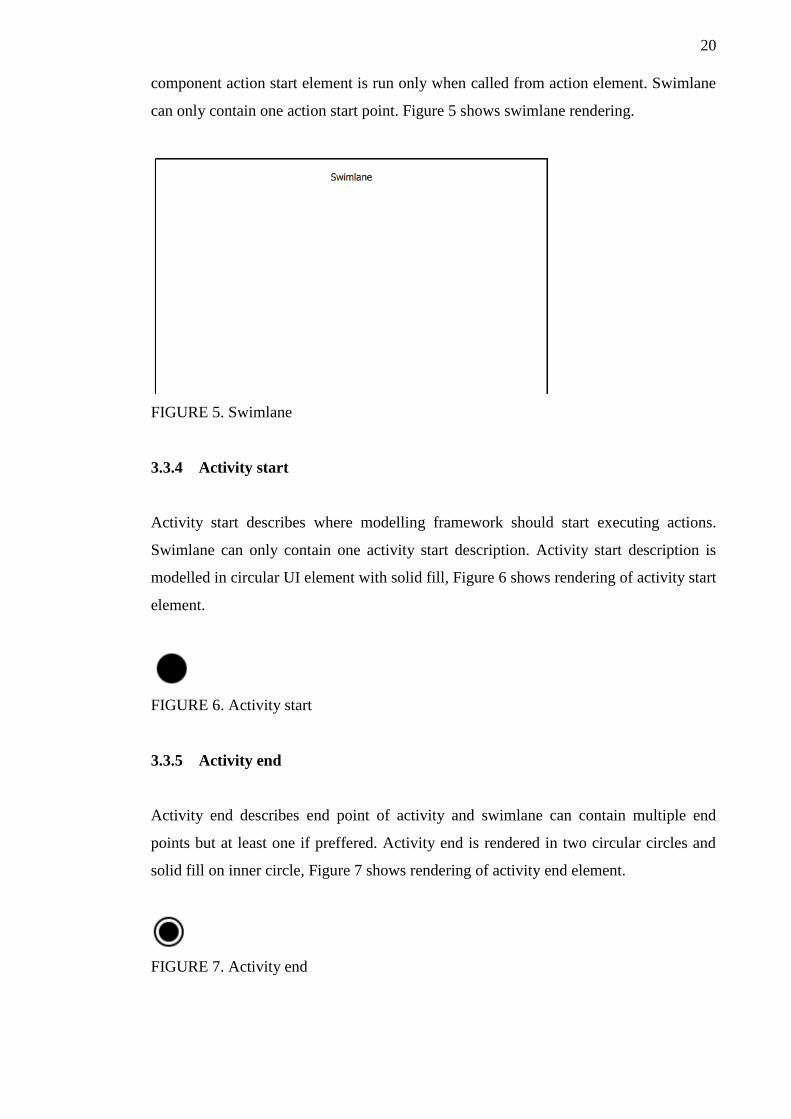
3.3.2 Activity diagram
Activity diagram allows model actions inside modelled component in component dia-
gram or inside virtual component that is created during model generation. Activity dia-
gram bases on swimlanes and their activity descriptions, swimlane can represent an
modelled component or virtual component that is generated automatically and acts as
standard function like in normal code development. Example of activity diagram in Fi-
gure 4.
FIGURE 4. Example activity.
3.3.3 Swimlane
Swimlane identifies modelled component in component diagram or virtual component
that will be created during model generation. If swimlane is modelled component and
not virtual component, its action start is automatically called during startup, this allows
concurrency support for components or initialization routines. If swimlane is virtual
20
component action start element is run only when called from action element. Swimlane
can only contain one action start point. Figure 5 shows swimlane rendering.
FIGURE 5. Swimlane
3.3.4 Activity start
Activity start describes where modelling framework should start executing actions.
Swimlane can only contain one activity start description. Activity start description is
modelled in circular UI element with solid fill, Figure 6 shows rendering of activity start
element.
FIGURE 6. Activity start
3.3.5 Activity end
Activity end describes end point of activity and swimlane can contain multiple end
points but at least one if preffered. Activity end is rendered in two circular circles and
solid fill on inner circle, Figure 7 shows rendering of activity end element.
FIGURE 7. Activity end
21
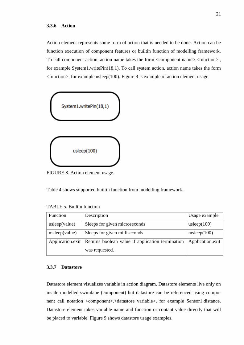
3.3.6 Action
Action element represents some form of action that is needed to be done. Action can be
function execution of component features or builtin function of modelling framework.
To call component action, action name takes the form <component name>.<function>.,
for example System1.writePin(18,1). To call system action, action name takes the form
<function>, for example usleep(100). Figure 8 is example of action element usage.
FIGURE 8. Action element usage.
Table 4 shows supported builtin function from modelling framework.
TABLE 5. Builtin function
Function Description Usage example
usleep(value) Sleeps for given microseconds usleep(100)
msleep(value) Sleeps for given milliseconds msleep(100)
Application.exit Returns boolean value if application termination
was requested.
Application.exit
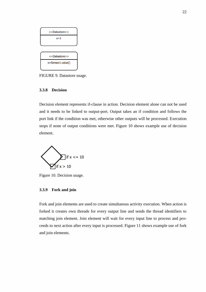
3.3.7 Datastore
Datastore element visualizes variable in action diagram. Datastore elements live only on
inside modelled swimlane (component) but datastore can be referenced using compo-
nent call notation <component>.<datastore variable>, for example Sensor1.distance.
Datastore element takes variable name and function or contant value directly that will
be placed to variable. Figure 9 shows datastore usage examples.
22
FIGURE 9. Datastore usage.
3.3.8 Decision
Decision element represents if-clause in action. Decision element alone can not be used
and it needs to be linked to output-port. Output takes an if condition and follows the
port link if the condition was met, otherwise other outputs will be processed. Execution
stops if none of output conditions were met. Figure 10 shows example use of decision
element.
Figure 10. Decision usage.
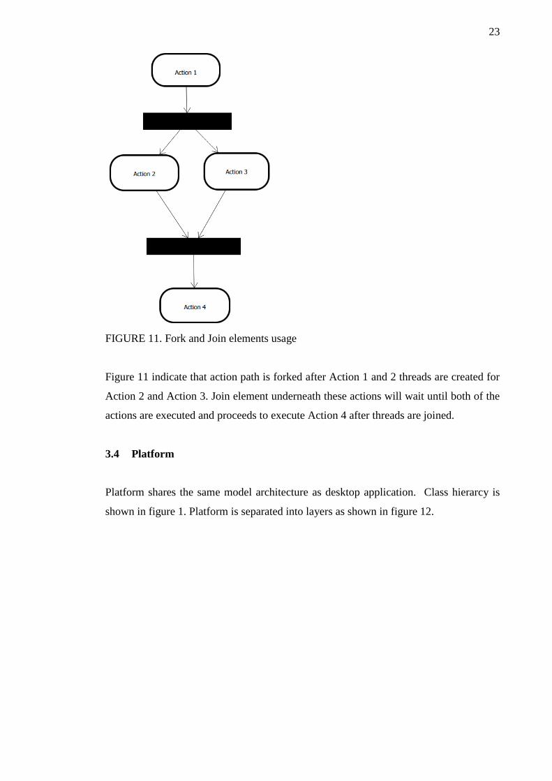
3.3.9 Fork and join
Fork and join elements are used to create simultanous activity execution. When action is
forked it creates own threads for every output line and sends the thread identifiers to
matching join element. Join element will wait for every input line to process and pro-
ceeds to next action after every input is processed. Figure 11 shows example use of fork
and join elements.
23
FIGURE 11. Fork and Join elements usage
Figure 11 indicate that action path is forked after Action 1 and 2 threads are created for
Action 2 and Action 3. Join element underneath these actions will wait until both of the
actions are executed and proceeds to execute Action 4 after threads are joined.
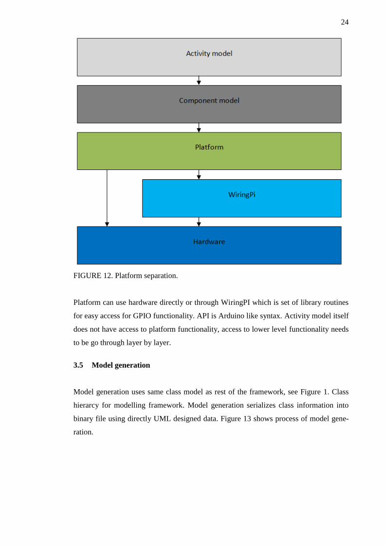
3.4 Platform
Platform shares the same model architecture as desktop application. Class hierarcy is
shown in figure 1. Platform is separated into layers as shown in figure 12.
24
FIGURE 12. Platform separation.
Platform can use hardware directly or through WiringPI which is set of library routines
for easy access for GPIO functionality. API is Arduino like syntax. Activity model itself
does not have access to platform functionality, access to lower level functionality needs
to be go through layer by layer.
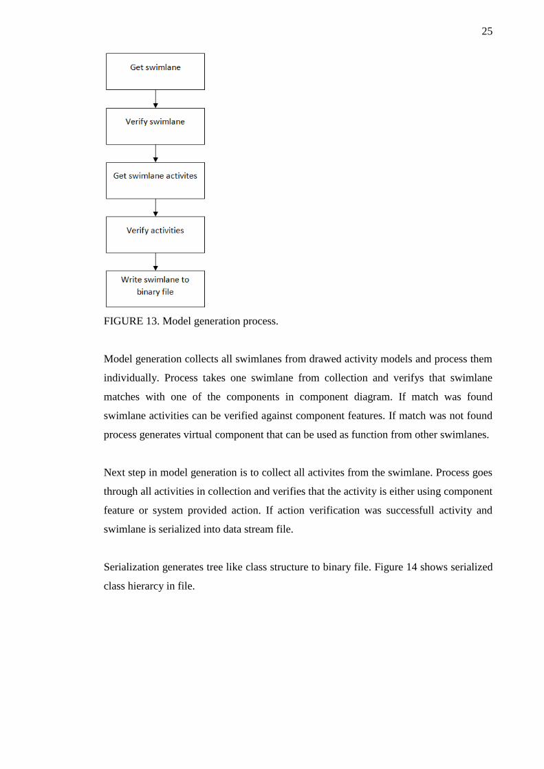
3.5 Model generation
Model generation uses same class model as rest of the framework, see Figure 1. Class
hierarcy for modelling framework. Model generation serializes class information into
binary file using directly UML designed data. Figure 13 shows process of model gene-
ration.
25
FIGURE 13. Model generation process.
Model generation collects all swimlanes from drawed activity models and process them
individually. Process takes one swimlane from collection and verifys that swimlane
matches with one of the components in component diagram. If match was found
swimlane activities can be verified against component features. If match was not found
process generates virtual component that can be used as function from other swimlanes.
Next step in model generation is to collect all activites from the swimlane. Process goes
through all activities in collection and verifies that the activity is either using component
feature or system provided action. If action verification was successfull activity and
swimlane is serialized into data stream file.
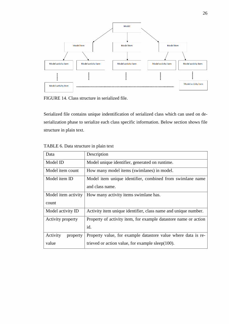
Serialization generates tree like class structure to binary file. Figure 14 shows serialized
class hierarcy in file.
26
FIGURE 14. Class structure in serialized file.
Serialized file contains unique indentification of serialized class which can used on de-
serialization phase to serialize each class specific information. Below section shows file
structure in plain text.
TABLE 6. Data structure in plain text
Data Description
Model ID Model unique identifier, generated on runtime.
Model item count How many model items (swimlanes) in model.
Model item ID Model item unique identifier, combined from swimlane name
and class name.
Model item activity
count
How many activity items swimlane has.
Model activity ID Activity item unique identifier, class name and unique number.
Activity property Property of activity item, for example datastore name or action
id.
Activity property
value
Property value, for example datastore value where data is re-
trieved or action value, for example sleep(100).
27
4 PROJECT
4.1 Goals
Project goal is to design component and activity diagrams using built modelling frame-
work. Component diagram contains platform Raspberry PI, motor actuators and sensors.
Activity diagram contains activity description for selected components.
UML diagrams that are modelled is built for 4 wheel drive robot car that can run on
constructed track. Track consist of walls that are used for distant measurement using
ultrasonic range finder.
4.2 Robot
Robot consists of following material:
4WD chassis kit
4 x DC motors
L298N IC as motor controller
UBEC
7.2v 1.5Ah Li-Po battery
Raspberry PI B
HC-SR04 ultrasonic sensor for distance measurement
Servo
4.2.1 Chassis and motors
Chassis kit was ready made 4 wheel drive kit manufactured by SparkFun that included 4
DC motors with suggested 3V input and 48:1 gearbox. Kit also included 65mm low-
profile wheels. (Multi-Chassis 4WD kit, HoppyTronics, 2015). DC Motors that were
included only had 800gf.cm torque on suggested 3V, this proved to be too low setting.
Kit could run forward and backwards with this torque but there was not enough torque
to make it turn. Increasing the input voltage from 3V to 7.2V increased the torque
enough the gain good speed on straight line and good cornering speeds. Battery holder
from figure 15 was removed to give more space for platform, motor controller and LiPo
battery.

28
PICTURE 6. Chassis (Multi-Chassis 4WD kit, HoppyTronics, 2015)
4.2.2 Motor controller
Motor controller that was selected for this project was L298N IC. L298N is dual chan-
nel motor controller that can run 2A load on each channel, 4A total. L298N provides
standard TTL logic level inputs to control load. Motor controller was operated from
Raspberry PI standard GPIO pins using software PWM output controlling the duty cy-
cle of motor controller. (L298N datasheet, Sparkfun, 2015)
PICTURE 7. L298N
4.2.3 Power system
Power system consists of standard 7.2V 1500mAh LiPo-battery with 25C discharge
rate. Discharge rate means that even if battery is only 1.5 Ah it can discarge it 25 times
the normal 1.5A rate, giving total of 37.5A but this decreases the battery capacity. For a
system that takes 1.5A it could run for on hour and for a 3A system, battery only have
capacity for 30 minutes.
Standard UBEC as voltage regulator was used for power distribution, separating the
Raspberry PI 5V and 7.2V directly from battery. UBEC could handle maximum of 6A,
which is enough to operate Raspberry PI and directly connected sensor power lines.
4.2.4 Raspberry PI
29
Raspberry PI B model was chosen as platform for this project. Raspberry PI was run-
ning debian linux distribution. Raspberry PI B contains features such as
Broadcom BCM2835 SoC
700 Mhz ARM1176JZF-s core CPU
Broadcom VideoCore 4 GPU
8 GPIO
UART, I2C and SPI
+3.3V, +5V and ground lines are directly provided from pins. Raspberry PI B does not
support +5V input voltage for GPIO, +5V needs to be converted to +3.3V, for example
using voltage dividers. Raspberry PI B only has one PWM support from hardware but
software could be used to simulate PWM with the cost of CPU resources.
PICTURE 8. Raspberry PI B
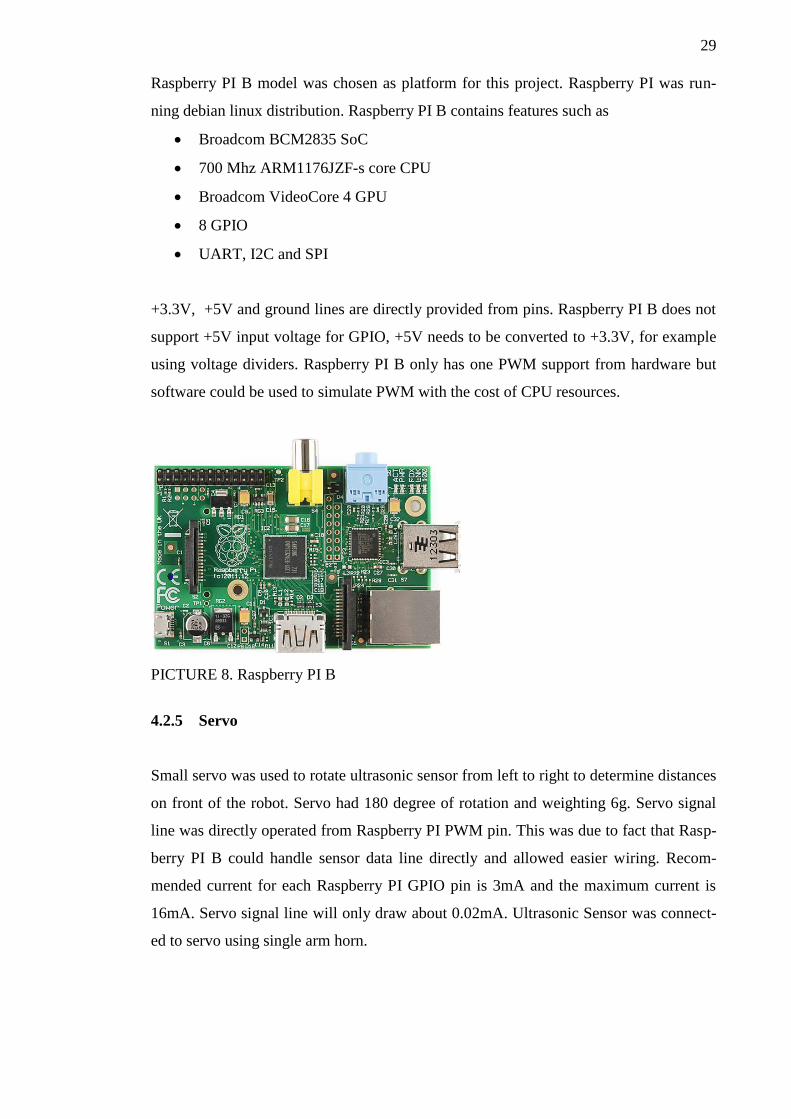
4.2.5 Servo
Small servo was used to rotate ultrasonic sensor from left to right to determine distances
on front of the robot. Servo had 180 degree of rotation and weighting 6g. Servo signal
line was directly operated from Raspberry PI PWM pin. This was due to fact that Rasp-
berry PI B could handle sensor data line directly and allowed easier wiring. Recom-
mended current for each Raspberry PI GPIO pin is 3mA and the maximum current is
16mA. Servo signal line will only draw about 0.02mA. Ultrasonic Sensor was connect-
ed to servo using single arm horn.
30
PICTURE 9. Servo
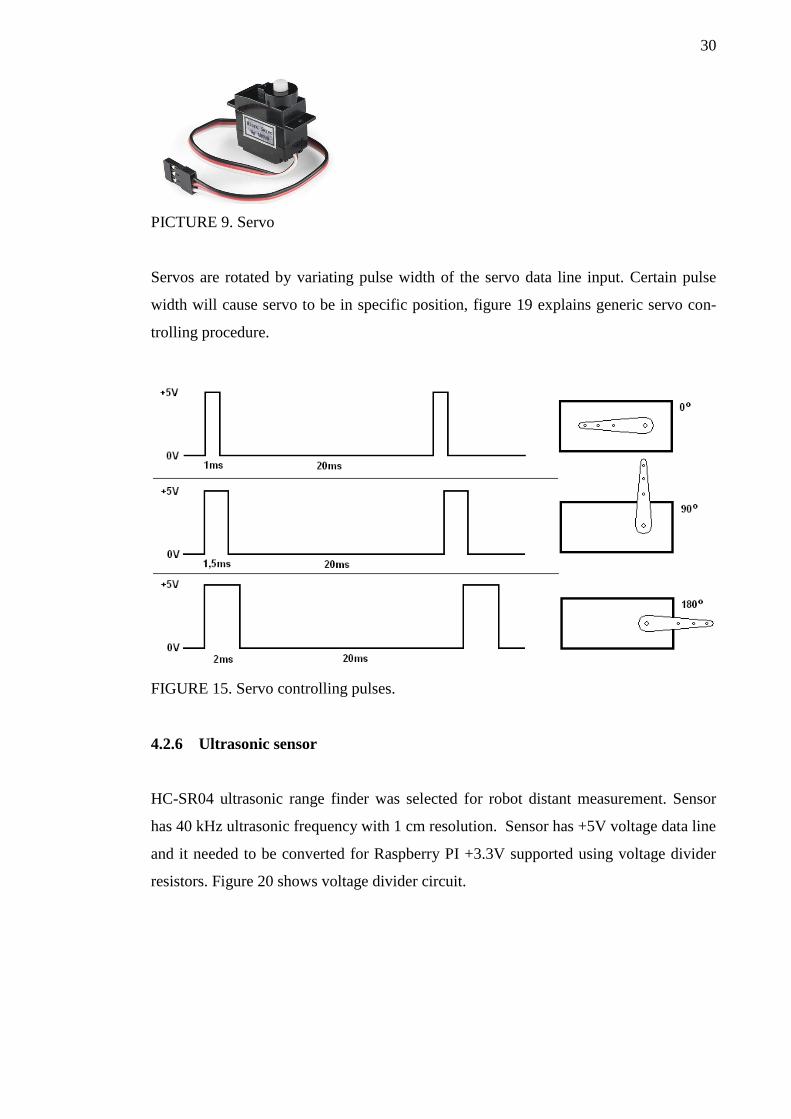
Servos are rotated by variating pulse width of the servo data line input. Certain pulse
width will cause servo to be in specific position, figure 19 explains generic servo con-
trolling procedure.
FIGURE 15. Servo controlling pulses.
4.2.6 Ultrasonic sensor
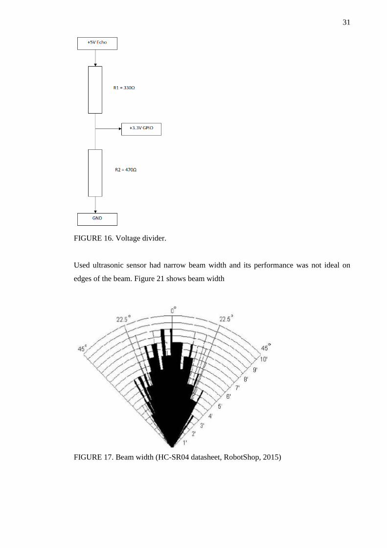
HC-SR04 ultrasonic range finder was selected for robot distant measurement. Sensor
has 40 kHz ultrasonic frequency with 1 cm resolution. Sensor has +5V voltage data line
and it needed to be converted for Raspberry PI +3.3V supported using voltage divider
resistors. Figure 20 shows voltage divider circuit.
31
FIGURE 16. Voltage divider.
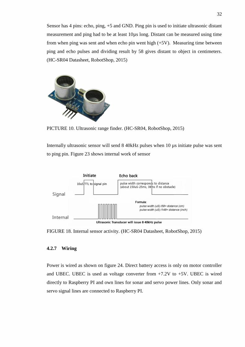
Used ultrasonic sensor had narrow beam width and its performance was not ideal on
edges of the beam. Figure 21 shows beam width
FIGURE 17. Beam width (HC-SR04 datasheet, RobotShop, 2015)
32
Sensor has 4 pins: echo, ping, +5 and GND. Ping pin is used to initiate ultrasonic distant
measurement and ping had to be at least 10µs long. Distant can be measured using time
from when ping was sent and when echo pin went high (+5V). Measuring time between
ping and echo pulses and dividing result by 58 gives distant to object in centimeters.
(HC-SR04 Datasheet, RobotShop, 2015)
PICTURE 10. Ultrasonic range finder. (HC-SR04, RobotShop, 2015)
Internally ultrasonic sensor will send 8 40kHz pulses when 10 µs initiate pulse was sent
to ping pin. Figure 23 shows internal work of sensor
FIGURE 18. Internal sensor activity. (HC-SR04 Datasheet, RobotShop, 2015)
4.2.7 Wiring
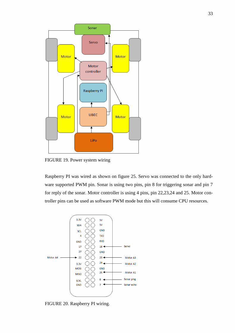
Power is wired as shown on figure 24. Direct battery access is only on motor controller
and UBEC. UBEC is used as voltage converter from +7.2V to +5V. UBEC is wired
directly to Raspberry PI and own lines for sonar and servo power lines. Only sonar and
servo signal lines are connected to Raspberry PI.
33
FIGURE 19. Power system wiring
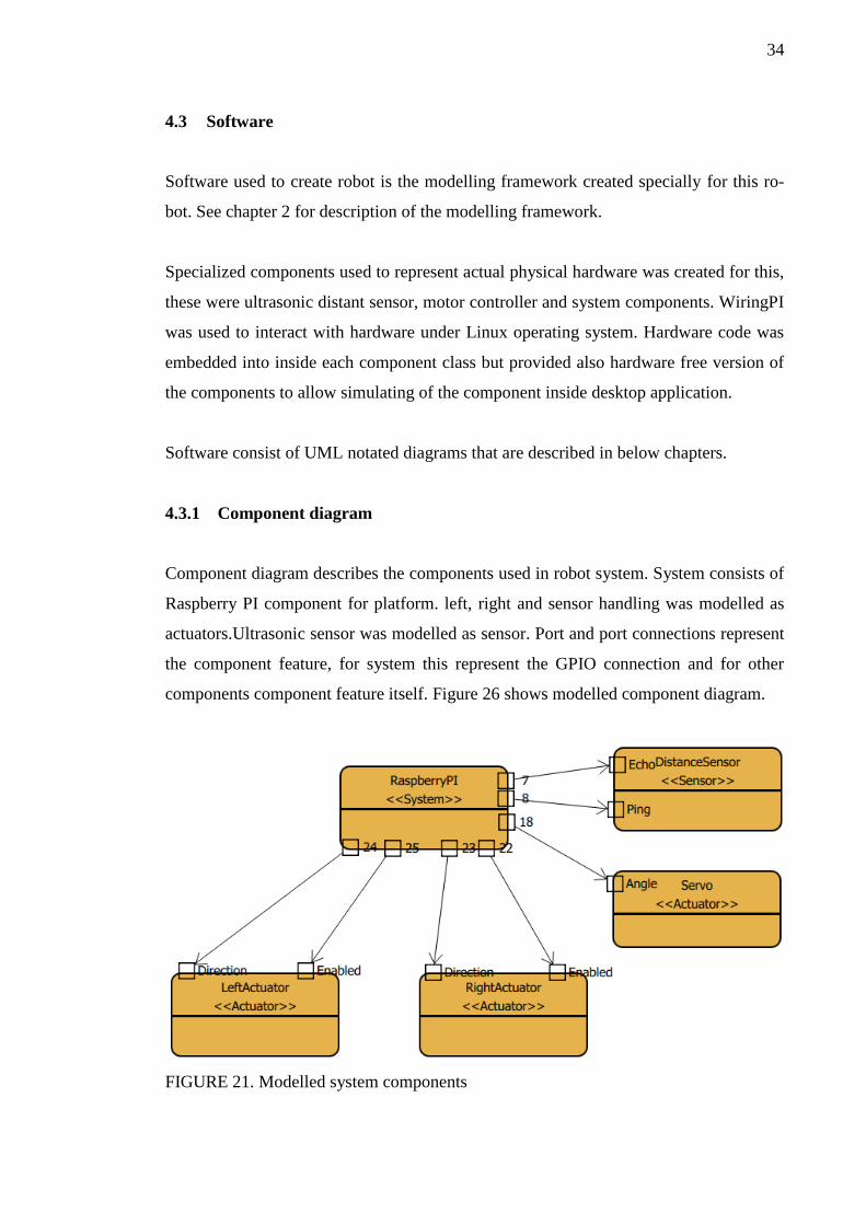
Raspberry PI was wired as shown on figure 25. Servo was connected to the only hard-
ware supported PWM pin. Sonar is using two pins, pin 8 for triggering sonar and pin 7
for reply of the sonar. Motor controller is using 4 pins, pin 22,23,24 and 25. Motor con-
troller pins can be used as software PWM mode but this will consume CPU resources.
FIGURE 20. Raspberry PI wiring.
34
4.3 Software
Software used to create robot is the modelling framework created specially for this ro-
bot. See chapter 2 for description of the modelling framework.
Specialized components used to represent actual physical hardware was created for this,
these were ultrasonic distant sensor, motor controller and system components. WiringPI
was used to interact with hardware under Linux operating system. Hardware code was
embedded into inside each component class but provided also hardware free version of
the components to allow simulating of the component inside desktop application.
Software consist of UML notated diagrams that are described in below chapters.
4.3.1 Component diagram
Component diagram describes the components used in robot system. System consists of
Raspberry PI component for platform. left, right and sensor handling was modelled as
actuators.Ultrasonic sensor was modelled as sensor. Port and port connections represent
the component feature, for system this represent the GPIO connection and for other
components component feature itself. Figure 26 shows modelled component diagram.
FIGURE 21. Modelled system components
35
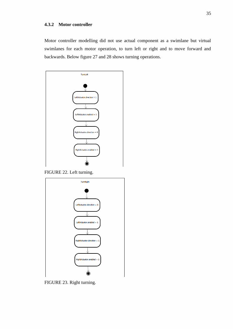
4.3.2 Motor controller
Motor controller modelling did not use actual component as a swimlane but virtual
swimlanes for each motor operation, to turn left or right and to move forward and
backwards. Below figure 27 and 28 shows turning operations.
FIGURE 22. Left turning.
FIGURE 23. Right turning.
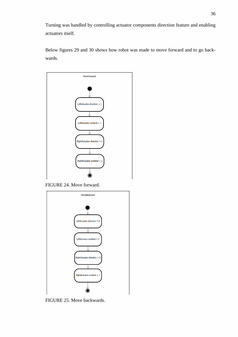
36
Turning was handled by controlling actuator components direction feature and enabling
actuators itself.
Below figures 29 and 30 shows how robot was made to move forward and to go back-
wards.
FIGURE 24. Move forward.
FIGURE 25. Move backwards.
37
Same features was used on forward and backwards moving as was used on turning. Di-
rection was set on each actuator and enabling actuators itself.
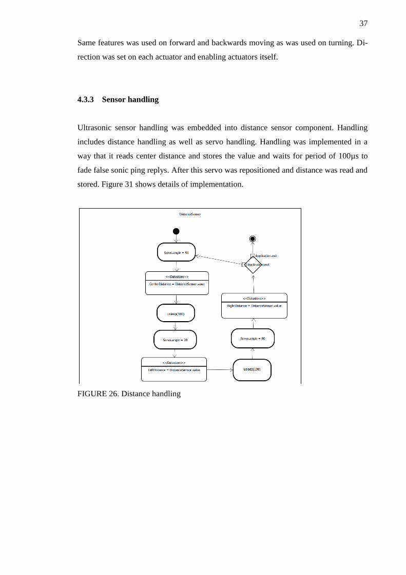
4.3.3 Sensor handling
Ultrasonic sensor handling was embedded into distance sensor component. Handling
includes distance handling as well as servo handling. Handling was implemented in a
way that it reads center distance and stores the value and waits for period of 100µs to
fade false sonic ping replys. After this servo was repositioned and distance was read and
stored. Figure 31 shows details of implementation.
FIGURE 26. Distance handling
38
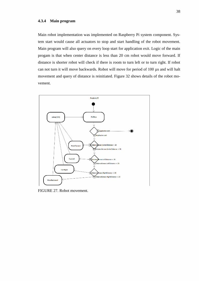
4.3.4 Main program
Main robot implementation was implemented on Raspberry Pi system component. Sys-
tem start would cause all actuators to stop and start handling of the robot movement.
Main program will also query on every loop start for application exit. Logic of the main
progam is that when center distance is less than 20 cm robot would move forward. If
distance is shorter robot will check if there is room to turn left or to turn right. If robot
can not turn it will move backwards. Robot will move for period of 100 µs and will halt
movement and query of distance is reinitiated. Figure 32 shows details of the robot mo-
vement.
FIGURE 27. Robot movement.
39
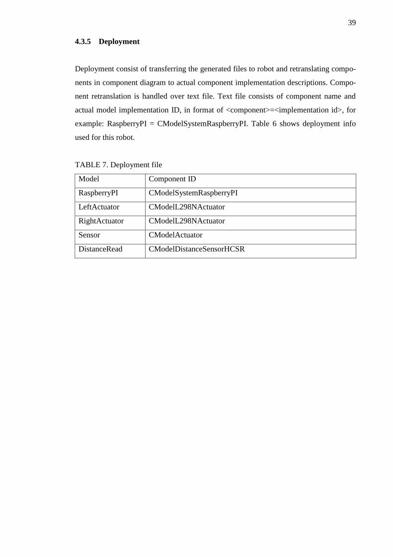
4.3.5 Deployment
Deployment consist of transferring the generated files to robot and retranslating compo-
nents in component diagram to actual component implementation descriptions. Compo-
nent retranslation is handled over text file. Text file consists of component name and
actual model implementation ID, in format of <component>=<implementation id>, for
example: RaspberryPI = CModelSystemRaspberryPI. Table 6 shows deployment info
used for this robot.
TABLE 7. Deployment file
Model Component ID
RaspberryPI CModelSystemRaspberryPI
LeftActuator CModelL298NActuator
RightActuator CModelL298NActuator
Sensor CModelActuator
DistanceRead CModelDistanceSensorHCSR
40
5 CONCLUSIONS AND FUTURE WORK
Considering the phases how project is implemented and the fact that phase 1 goal was to
introduce UML-like notation to model robot and have the ability to create robot that
moves and detects blocking items, project was success. Next phases will introduce more
features and more importantly ROS integration. Key concept is to extend component
library that modelling framework supports. ROS already has large device driver support
but these device drivers needs to be wrapped into component diagram.
5.1 ROS Support
ROS (Robot operatin system) is set of libraries, hardware abstraction and device drivers
to ease robot building. In addition it includes visualizers, message-passing and many
other features. In core ROS is message-passing library where message has publisher and
subscriber. Message can be for example a command to move forward where system
component is publishing move command and actuator handler is subscriber and handles
the passed message.
For modelling framework this could be achieved by having support for sequence dia-
gram, interaction diagram or by activity diagram by introducing signal - slot activities.
5.2 Debugging support
Modelling framework already has state machine inside, this means that the activity that
is executed is already known. This information needs to be passed to desktop applica-
tion through serial or wlan. Using the same state machine it is easy to add performance
metric information, measuring the times how long each activity action took and passing
the metric information to desktop application.
5.3 Plugin loading
Applications already uses Qt-framework for mainly cross-platform support but Qt usage
could be extended for plugin loading as it already have the feature built-in. Modelling
framework could build component toolbox based on available component plugins.
41
Since the modelling framework has the desktop and platform side, plugins should be
restricted or at least supported so that UI and platform has different plugin implementa-
tion.
5.4 Code generation
Code generation should be supported in case performance is key requirement for robot
system, as it often is. Code generation could be supported by generating activity
(swimlane) c++ code with cross-platform build system. System components that are
open sourced can be included directly to build system but code generation can use
plugin loading support for components where code is not available or restricted due to
licensing.
5.5 Distance measurement using stereo vision
Ultrasonic distance measurement has it drawbacks depending on the environment its
used. Soft materials absord the sonic wave and in worst case sensor can not handle low
sensitivity echos and can not calculate distance at all. Other drawback is that depending
on the angle of the robot and wall or any object which is used for distance measurement,
if the angle is off, reflected wave is not returning to sensor. These can be fixed by using
higher quality sensor which beam width is greater enough and more sensitive echo sen-
sor.
Using stereo vision it should be possible to determine objects distance by using two
separate camera images and creating depth buffer from images. This method needs at
least initial calibration and recalibration when cameras are repositioned in robot.
42
REFERENCES
Robotics, Wikipedia. https://en.wikipedia.org/wiki/Robotics Referenced on 29.8.2015
Introduction to robotics, VEX Robotics.
http://curriculum.vexrobotics.com/curriculum/intro-to-robotics/what-is-robotics Refer-
enced on 29.8.2015
Assembly robot, Metalworking magazine.
http://www.metalworkingworldmagazine.com/growth-forecast-for-robotics-market-to-
2020/ Referenced on 30.8.2015
Mars rover, Wikipedia. https://en.wikipedia.org/wiki/Mars_rover Referenced on
30.8.2015
Military robot, Wikipedia. https://en.wikipedia.org/wiki/Military_robot Referenced on
30.8.2015
MQ-1 Predator, Wikipedia. https://en.wikipedia.org/wiki/General_Atomics_MQ-
1_Predator Referenced on 30.8.2015
Phalanx CIWS, Wikipedia. https://en.wikipedia.org/wiki/Phalanx_CIWS Referenced on
30.8.2015
Educational robotics, Wikipedia. https://en.wikipedia.org/wiki/Educational_robotics
Referenced on 30.8.2015
DARwIn-OP, Wikipedia. https://en.wikipedia.org/wiki/DARwIn-OP Referenced on
30.8.2015
Rise of robots infographic, Robobusiness.
http://www.robobusiness.com/images/uploads/RB15_Rise_of_Robots_Infographic.pdf
Referenced on 30.8.2015
Robotics software, European PhD school.
http://www.phdschoolinrobotics.eu/ContentIntroduction.html Referenced on 6.9.215
Artiticial intelligence, Wikipedia. https://en.wikipedia.org/wiki/Artificial_intelligence
Referenced on 6.9.2015
Multi-Chassis 4WD kit, HoppyTronics. http://www.hobbytronics.co.uk/4wd-chassis-kit
Referenced on 26.7.2015.
L298N datasheet, Sparkfun.
https://www.sparkfun.com/datasheets/Components/General/L298N.pdf Referenced
26.7.2015.
HC-SR04 datasheet, RobotShop. http://www.robotshop.com/media/files/pdf/datasheet-
sen026.pdf Referenced 26.7.2015.

43
HC-SR04, RobotShop. http://www.robotshop.com/en/hc-sr04-ultrasonic-range-
finder.html Referenced 26.7.2015.