model-based integration of reusable component … integration of reusable component-based avionics...
TRANSCRIPT
Wendy Roll - 1OMG RTWS 2003
Model-Based Integration of Reusable Component-Based
Avionics Systems
Model-Based Integration of Reusable Component-Based
Avionics SystemsWendy Roll
The Boeing CompanyPhantom Works
St. Louis, MO
This work was sponsored by the DARPA/IXO Model-Based Integration of Embedded Software program, under contract F33615-00-C-1704 with Air Force Research Laboratory Information Directorate, Wright-Patterson Air Force Base.
Wendy Roll - 2OMG RTWS 2003
OutlineOutline
• DARPA Model-Based Integration of Embedded Software Program Introduction
• Boeing Open Experimental Platform Overview
• Model-Based Integration Vision– Context– Multi-view Modeling– Model-based Analysis– Model-based Composition– Resultant Process
• Experimentation• Conclusion
Wendy Roll - 3OMG RTWS 2003
MoBIES ObjectivesMoBIES Objectives
main {. . .
}
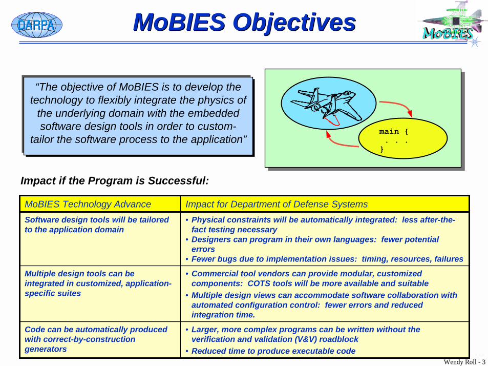
Impact if the Program is Successful:
“The objective of MoBIES is to develop the technology to flexibly integrate the physics of
the underlying domain with the embedded software design tools in order to custom-
tailor the software process to the application”
• Larger, more complex programs can be written without the verification and validation (V&V) roadblock
• Reduced time to produce executable code
Code can be automatically produced with correct-by-construction generators
• Commercial tool vendors can provide modular, customized components: COTS tools will be more available and suitable
• Multiple design views can accommodate software collaboration with automated configuration control: fewer errors and reduced integration time.
Multiple design tools can be integrated in customized, application-specific suites
• Physical constraints will be automatically integrated: less after-the-fact testing necessary
• Designers can program in their own languages: fewer potential errors
• Fewer bugs due to implementation issues: timing, resources, failures
Software design tools will be tailored to the application domain
Impact for Department of Defense SystemsMoBIES Technology Advance
Wendy Roll - 4OMG RTWS 2003
Boeing OEP Project SummaryBoeing OEP Project Summary
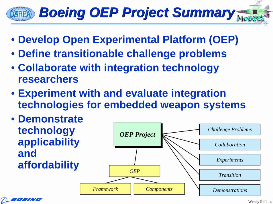
• Develop Open Experimental Platform (OEP)• Define transitionable challenge problems• Collaborate with integration technology
researchers• Experiment with and evaluate integration
technologies for embedded weapon systems
OEP ProjectOEP ProjectChallenge Problems
Collaboration
Experiments
Transition
Demonstrations
OEP
Framework Components
• Demonstrate technology applicability and affordability
Wendy Roll - 5OMG RTWS 2003
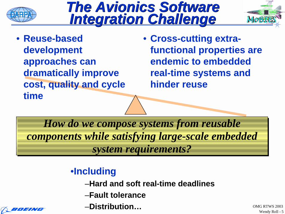
The Avionics Software Integration ChallengeThe Avionics Software Integration Challenge
• Reuse-based development approaches can dramatically improve cost, quality and cycle time
• Cross-cutting extra-functional properties are endemic to embedded real-time systems and hinder reuse
•Including–Hard and soft real-time deadlines–Fault tolerance–Distribution…
How do we compose systems from reusable components while satisfying large-scale embedded
system requirements?
How do we compose systems from reusable components while satisfying large-scale embedded
system requirements?
Wendy Roll - 6OMG RTWS 2003
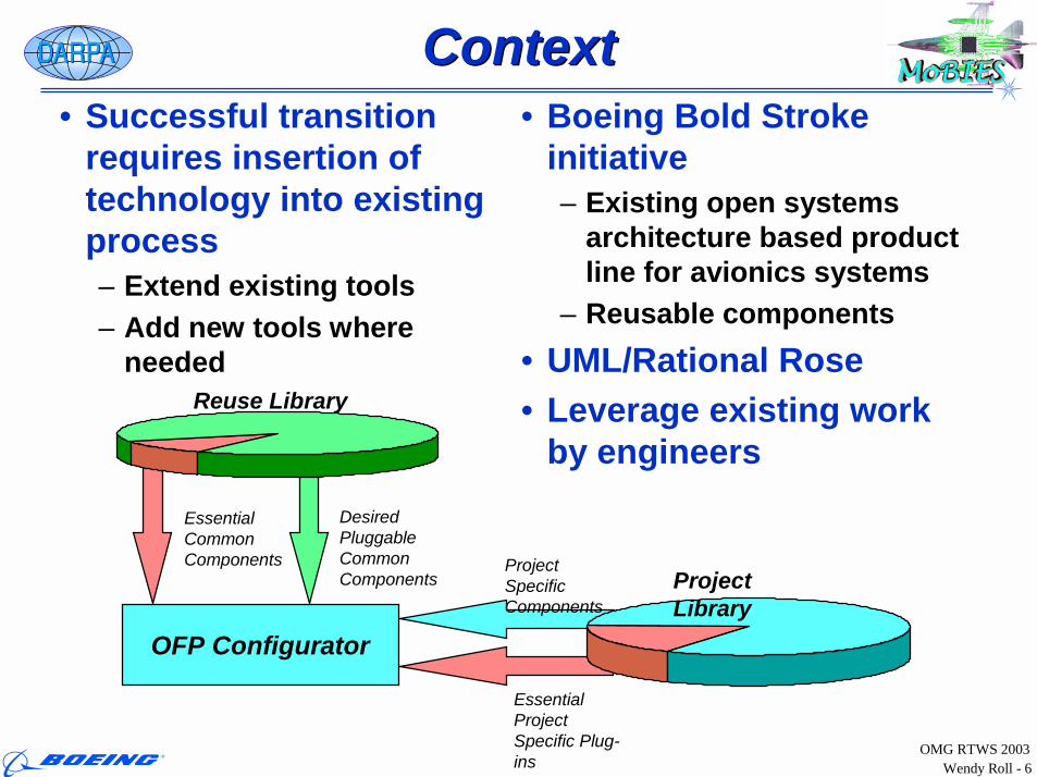
ContextContext• Successful transition
requires insertion of technology into existing process– Extend existing tools– Add new tools where
needed
• Boeing Bold Stroke initiative– Existing open systems
architecture based product line for avionics systems
– Reusable components• UML/Rational Rose• Leverage existing work
by engineers
Project Specific Components
Essential Project Specific Plug-ins
Essential Common Components
Desired Pluggable Common Components
OFP Configurator
Project Library
Reuse Library
Wendy Roll - 7OMG RTWS 2003
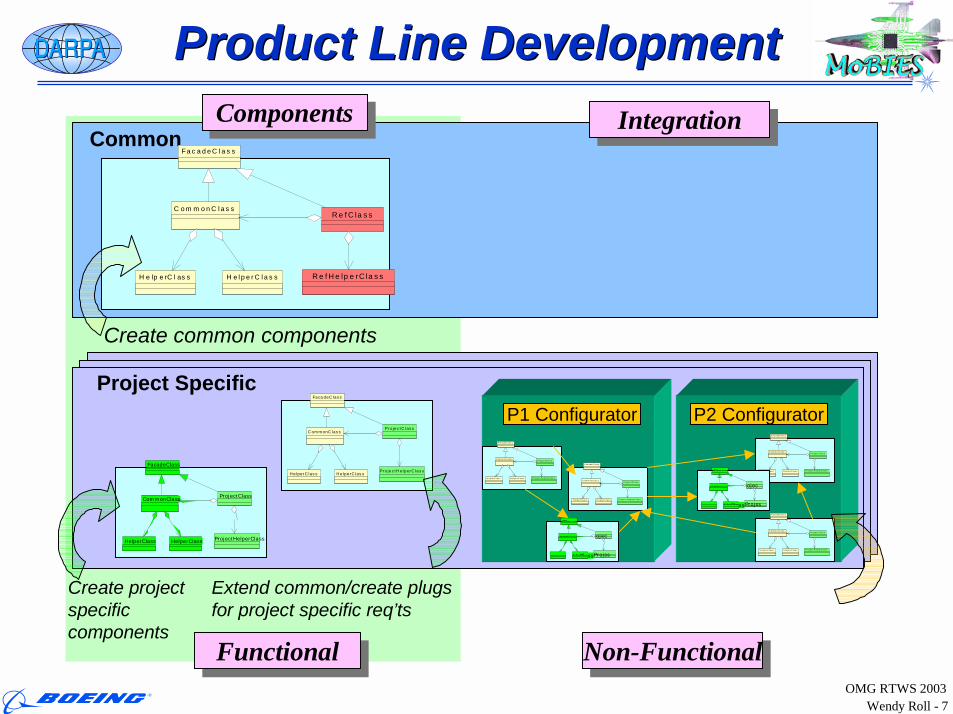
Product Line DevelopmentProduct Line Development
H e lp e rC l as s
F ac a deC la s s
H el pe rC la s s
C omm onC la s sP ro je c tC la s s
P ro j ec t H elp erC la s s
H e lp erC l as s
F ac a de C la s s
H el pe rC l as s
C ommo nC l as sP ro je c tC la s s
P ro jec t H el p erC l a s s
H e lp e rC l as s
F ac a deC la s s
H el pe rC l a s s
C ommo nC l as sP ro je c tC la s s
P ro jec t H elp erC la s s
H e lp e rC l as s
F ac a deC la s s
H el pe rC l a s s
C ommo nC l as sP ro je c tC la s s
P ro jec t H elp erC la s s
Common
Project Specific
HelperC las s
Faca deC lass
HelperC las s
C ommonC lassP rojectC lass
P rojectHelperC lass
H e lp e rC l as s
F a c a deC la s s
H elpe rC la s s
C om m onC las sR e fC la s s
R e fH e lp e rC la s s
Create common components
Configure for project deployment
P1 Configurator P2 Configurator
HelperClass
FacadeClass
HelperClass
CommonClassProjectClass
ProjectHelperClass
Class
HrClass
ass ojec
Projss
Class
HrClass
ass ojec
Projss
FunctionalFunctional Non-FunctionalNon-Functional
Extend common/create plugs for project specific req’ts
Create projectspecific components
ComponentsComponents IntegrationIntegration
Wendy Roll - 8OMG RTWS 2003
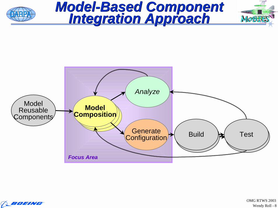
Model-Based Component Integration Approach
Model-Based Component Integration Approach
Focus Area
Build Test
ModelModel
Analyze
GenerateConfiguration Build Test
ModelComposition
ModelReusable
Components
Wendy Roll - 9OMG RTWS 2003
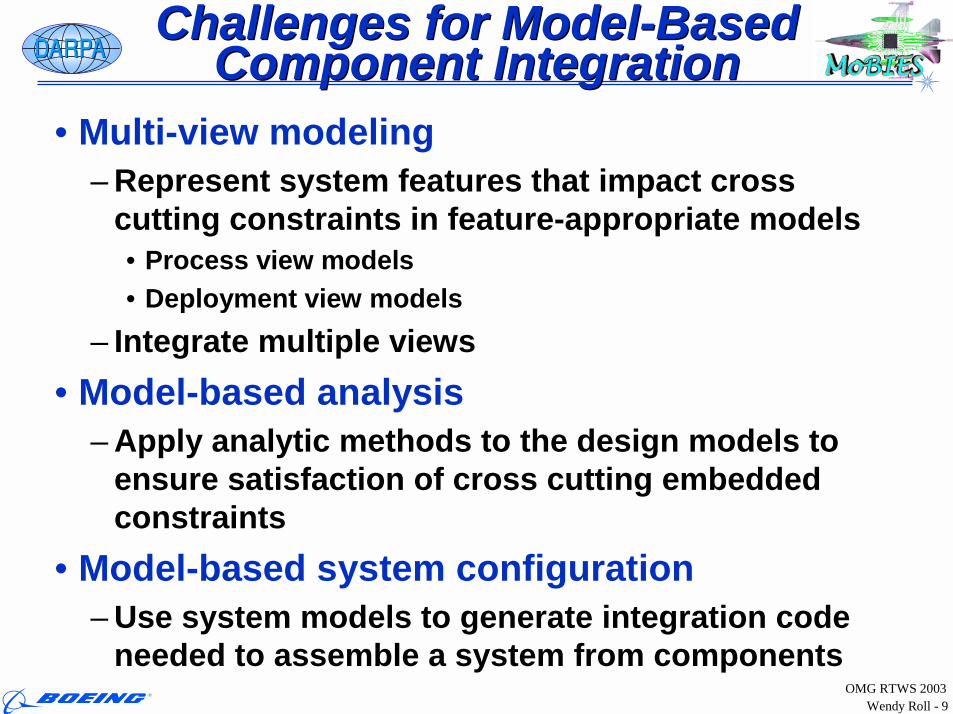
Challenges for Model-Based Component Integration
Challenges for Model-Based Component Integration
• Multi-view modeling– Represent system features that impact cross
cutting constraints in feature-appropriate models• Process view models• Deployment view models
– Integrate multiple views• Model-based analysis
– Apply analytic methods to the design models to ensure satisfaction of cross cutting embedded constraints
• Model-based system configuration– Use system models to generate integration code
needed to assemble a system from components
Wendy Roll - 10OMG RTWS 2003
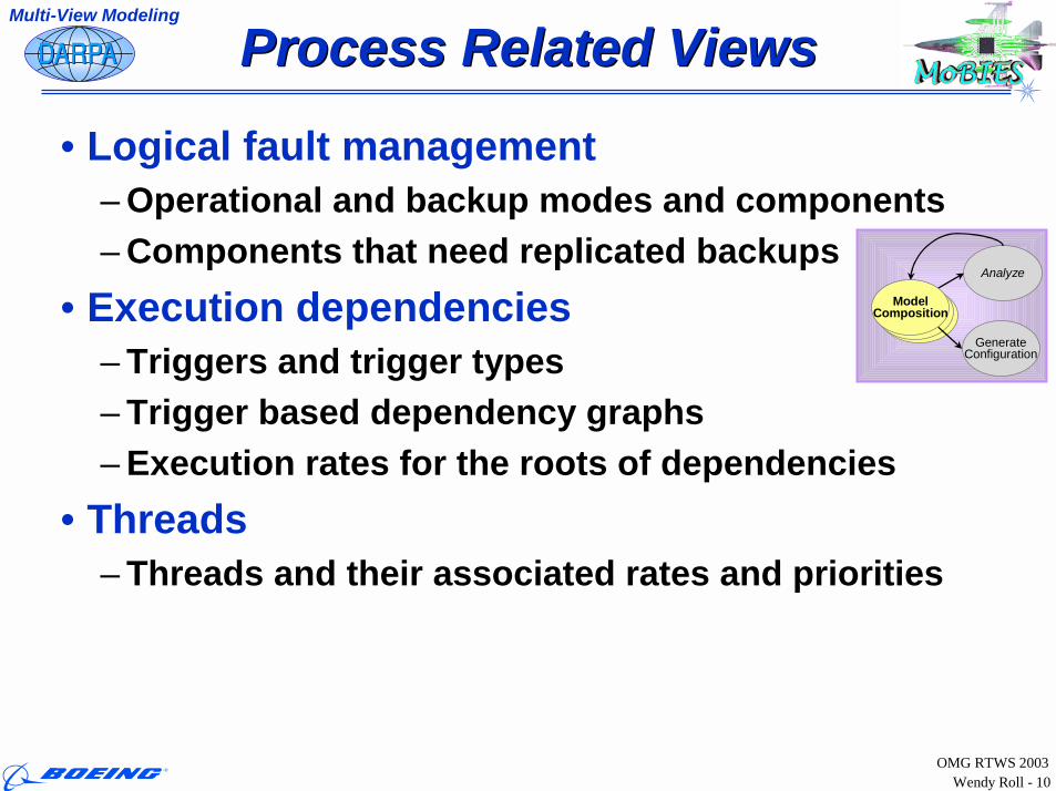
Process Related ViewsProcess Related Views
• Logical fault management– Operational and backup modes and components– Components that need replicated backups
• Execution dependencies– Triggers and trigger types– Trigger based dependency graphs – Execution rates for the roots of dependencies
• Threads– Threads and their associated rates and priorities
Multi-View Modeling
ModelModel
Analyze
GenerateConfiguration
ModelComposition
Wendy Roll - 11OMG RTWS 2003
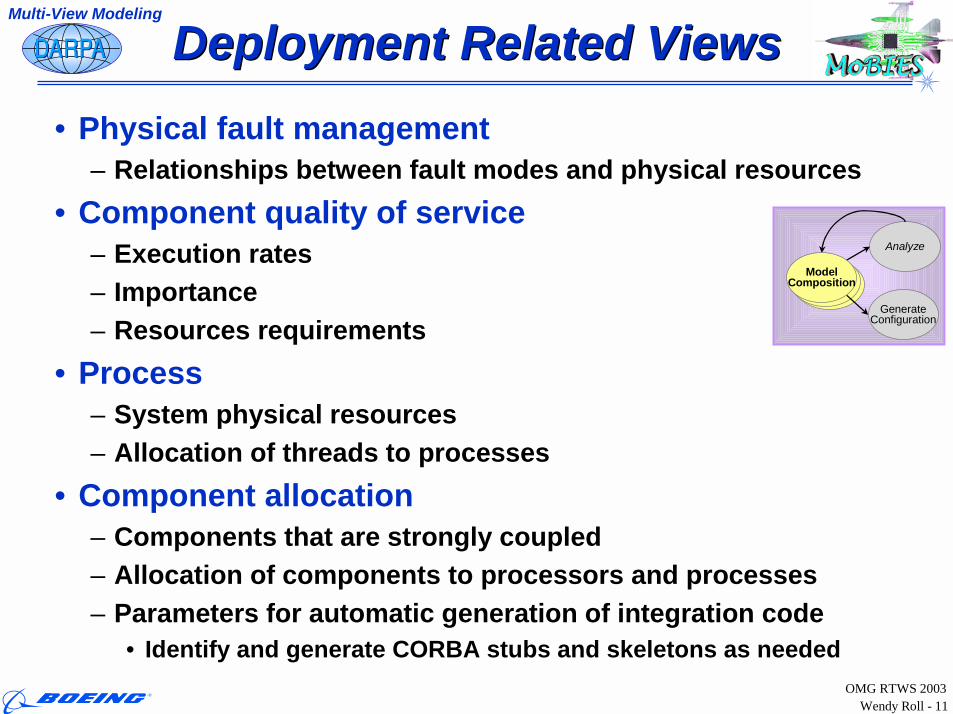
Deployment Related ViewsDeployment Related Views• Physical fault management
– Relationships between fault modes and physical resources• Component quality of service
– Execution rates– Importance– Resources requirements
• Process– System physical resources– Allocation of threads to processes
• Component allocation– Components that are strongly coupled– Allocation of components to processors and processes– Parameters for automatic generation of integration code
• Identify and generate CORBA stubs and skeletons as needed
Multi-View Modeling
ModelModel
Analyze
GenerateConfiguration
ModelComposition
Wendy Roll - 12OMG RTWS 2003
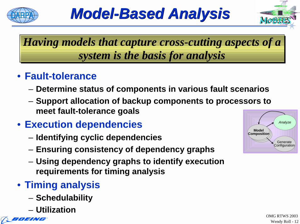
Model-Based AnalysisModel-Based Analysis
• Fault-tolerance– Determine status of components in various fault scenarios– Support allocation of backup components to processors to
meet fault-tolerance goals• Execution dependencies
– Identifying cyclic dependencies– Ensuring consistency of dependency graphs– Using dependency graphs to identify execution
requirements for timing analysis• Timing analysis
– Schedulability– Utilization
ModelModel
Analyze
GenerateConfiguration
ModelComposition
Having models that capture cross-cutting aspects of a system is the basis for analysis
Having models that capture cross-cutting aspects of a system is the basis for analysis
Wendy Roll - 13OMG RTWS 2003
Model-Based ConfigurationModel-Based Configuration
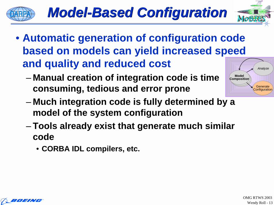
• Automatic generation of configuration code based on models can yield increased speed and quality and reduced cost– Manual creation of integration code is time
consuming, tedious and error prone– Much integration code is fully determined by a
model of the system configuration– Tools already exist that generate much similar
code• CORBA IDL compilers, etc.
ModelModel
Analyze
GenerateConfiguration
ModelComposition
Wendy Roll - 14OMG RTWS 2003
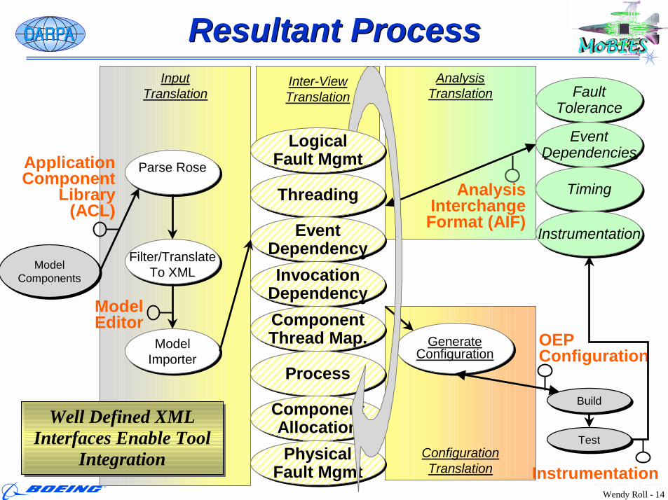
Inter-ViewTranslation
ConfigurationTranslation
GenerateConfiguration
GenerateConfiguration
AnalysisTranslation
InputTranslation
Resultant ProcessResultant Process
BuildBuild
TestTest
ThreadingThreading
EventDependency
EventDependency
InvocationDependencyInvocation
DependencyComponentThread Map.ComponentThread Map.
ProcessProcess
ComponentAllocation
ComponentAllocationPhysical
Fault MgmtPhysical
Fault Mgmt
FaultTolerance
FaultTolerance
EventDependencies
EventDependencies
TimingTiming
LogicalFault Mgmt
LogicalFault Mgmt
ModelComponents
ModelComponents
Parse RoseParse Rose
Filter/TranslateTo XML
Filter/TranslateTo XML
ModelImporterModel
Importer
Application Component
Library (ACL)
Analysis Interchange Format (AIF)
OEP Configuration
Model Editor
Instrumentation
Well Defined XML Interfaces Enable Tool
Integration
Well Defined XML Interfaces Enable Tool
Integration
InstrumentationInstrumentation
Wendy Roll - 15OMG RTWS 2003
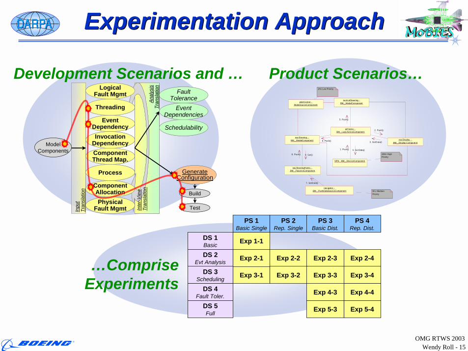
Experimentation ApproachExperimentation Approach
Inpu
tTr
ansl
atio
n
Build
Test
ModelComponents
Anal
ysis
Tran
slat
ion
Anal
ysis
Tran
slat
ionLogical
Fault Mgmt
Threading
EventDependencyInvocation
DependencyComponentThread Map.
Process
ComponentAllocationPhysical
Fault Mgmt
LogicalFault Mgmt
Threading
EventDependencyInvocation
DependencyComponentThread Map.
Process
ComponentAllocationPhysical
Fault Mgmt Inte
r-Vie
wTr
ansl
atio
n
FaultTolerance
EventDependencies
Schedulability
FaultTolerance
EventDependencies
Schedulability
GenerateConfiguration
GenerateConfiguration
Development Scenarios and … Product Scenarios…
…CompriseExperiments
PS 1Basic Single
PS 2Rep. Single
PS 3Basic Dist.
Exp 1-1
Exp 2-2
DS 1Basic
DS 2Evt Analysis
DS 3Scheduling
DS 4Fault Toler.
DS 5Full
PS 4Rep. Dist.
Exp 5-4
Exp 4-3
Exp 3-1
Exp 2-3
Exp 3-2 Exp 3-3
Exp 5-3
Exp 2-1 Exp 2-4
Exp 3-4
Exp 4-4
airf rame : BM__Lazy Activ eComponent
tacticalSteering : BM__ModalCom ponent
nav Display : BM__Dis play Compo nent
GPS : BM__Dev iceComponent
nav Steering : BM__ModalComponent
nav SteeringPoints : BM__Passiv eComponent
nav igator : BM__PushDataSourceComponent
pilotControl : ModeSourceComponent
5H z Medium Priorit y
1Hz Low Priority
20Hz High Priority
5. Push()
6. Push()
2. Push()
3. GetData()
9. Get()8. Push()
1. Push() 4. GetData()
7. SetData()
Wendy Roll - 16OMG RTWS 2003
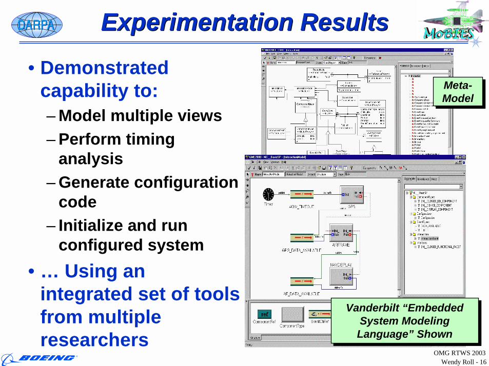
Experimentation ResultsExperimentation Results
• Demonstrated capability to:– Model multiple views– Perform timing
analysis– Generate configuration
code– Initialize and run
configured system• … Using an
integrated set of tools from multiple researchers
Meta-ModelMeta-Model
Vanderbilt “Embedded System Modeling Language” Shown
Vanderbilt “Embedded System Modeling Language” Shown
Wendy Roll - 17OMG RTWS 2003
Current StatusCurrent Status
• Heavy Focus Now On Preparing For Transition Of Component-Oriented Programming– Filling in capability gaps– Increasing scalability, usability…– Optimizing run-time performance
• Realistic evaluation of– Overall approach– Integrated tool sets– Individual tools
Wendy Roll - 18OMG RTWS 2003
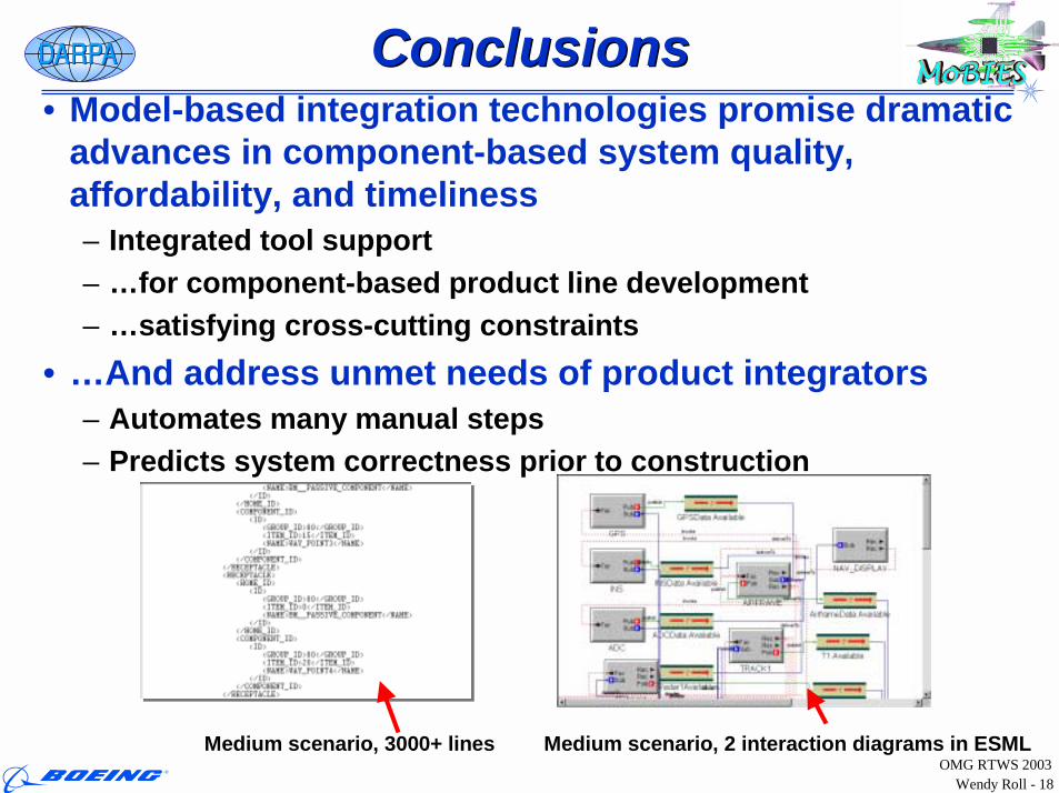
ConclusionsConclusions• Model-based integration technologies promise dramatic
advances in component-based system quality, affordability, and timeliness– Integrated tool support – …for component-based product line development – …satisfying cross-cutting constraints
• …And address unmet needs of product integrators– Automates many manual steps– Predicts system correctness prior to construction
Medium scenario, 3000+ lines Medium scenario, 2 interaction diagrams in ESML