model cbl - r.f. macdonald co. · model cbl 800-1800 hp boilers 3 features and benefits the cbl...
TRANSCRIPT

102/2016
TABLE OF CONTENTSFEATURES AND BENEFITS . . . . . . . . . . . . . . . . . . . . . . . . . . . . . . . . . . . . . . . . . . . . . . . . . . . . . . . . 3Three Pass or Four Pass Design: . . . . . . . . . . . . . . . . . . . . . . . . . . . . . . . . . . . . . . . . . . . . . . . . . . . . . 3Front and Rear Doors: . . . . . . . . . . . . . . . . . . . . . . . . . . . . . . . . . . . . . . . . . . . . . . . . . . . . . . . . . . . . 3Natural Gas, No. 2 Oil, No. 6 Oil, or Combination Burners Available: . . . . . . . . . . . . . . . . . . . . . . . . . . . 3PRODUCT OFFERING . . . . . . . . . . . . . . . . . . . . . . . . . . . . . . . . . . . . . . . . . . . . . . . . . . . . . . . . . . . . 3DIMENSIONS AND RATINGS . . . . . . . . . . . . . . . . . . . . . . . . . . . . . . . . . . . . . . . . . . . . . . . . . . . . . . . 4PERFORMANCE DATA . . . . . . . . . . . . . . . . . . . . . . . . . . . . . . . . . . . . . . . . . . . . . . . . . . . . . . . . . . . . 9Efficiency . . . . . . . . . . . . . . . . . . . . . . . . . . . . . . . . . . . . . . . . . . . . . . . . . . . . . . . . . . . . . . . . . . . . . 9ENGINEERING DATA . . . . . . . . . . . . . . . . . . . . . . . . . . . . . . . . . . . . . . . . . . . . . . . . . . . . . . . . . . . . 10Boiler Information . . . . . . . . . . . . . . . . . . . . . . . . . . . . . . . . . . . . . . . . . . . . . . . . . . . . . . . . . . . . . . 10Burner/Control Information . . . . . . . . . . . . . . . . . . . . . . . . . . . . . . . . . . . . . . . . . . . . . . . . . . . . . . . . 10Burner Characteristics . . . . . . . . . . . . . . . . . . . . . . . . . . . . . . . . . . . . . . . . . . . . . . . . . . . . . . . . . . . 10Gas-Fired Burners . . . . . . . . . . . . . . . . . . . . . . . . . . . . . . . . . . . . . . . . . . . . . . . . . . . . . . . . . . . . . . 11Fuel Connections - Gas . . . . . . . . . . . . . . . . . . . . . . . . . . . . . . . . . . . . . . . . . . . . . . . . . . . . . . . . . . 11Fuel Connections - Oil . . . . . . . . . . . . . . . . . . . . . . . . . . . . . . . . . . . . . . . . . . . . . . . . . . . . . . . . . . . 11Boiler Room Information . . . . . . . . . . . . . . . . . . . . . . . . . . . . . . . . . . . . . . . . . . . . . . . . . . . . . . . . . 12Stack Support Capabilities . . . . . . . . . . . . . . . . . . . . . . . . . . . . . . . . . . . . . . . . . . . . . . . . . . . . . . . . 12Boiler Room Combustion Air . . . . . . . . . . . . . . . . . . . . . . . . . . . . . . . . . . . . . . . . . . . . . . . . . . . . . . . 12Stack/Breeching Size Criteria . . . . . . . . . . . . . . . . . . . . . . . . . . . . . . . . . . . . . . . . . . . . . . . . . . . . . . 12SAMPLE SPECIFICATIONS . . . . . . . . . . . . . . . . . . . . . . . . . . . . . . . . . . . . . . . . . . . . . . . . . . . . . . . . 21
Model CBL 800-1600 HP
2
800-1600 HP Section A5
ILLUSTRATIONSFigure A5-1. CBL Steam Boiler Dimensions, 4 Pass (Page 1 of 2) (4 pass) . . . . . . . . . . . . . . . . . . . . . . .7Figure A5-2. Space Required to Open Rear Doors on CBL Boilers . . . . . . . . . . . . . . . . . . . . . . . . . . . . . .9Figure A5-3. CBL Boilers Lifting Lug Location . . . . . . . . . . . . . . . . . . . . . . . . . . . . . . . . . . . . . . . . . . . .9Figure A5-4. CBL Boiler Mounting Piers . . . . . . . . . . . . . . . . . . . . . . . . . . . . . . . . . . . . . . . . . . . . . . .10Figure A5-5. No. 2 Oil Piping, Single Boiler Installation, Oil Pump Integral With Boiler . . . . . . . . . . . . . .19Figure A5-6. No. 6 Oil Piping, Single Boiler Installation, Remote Oil Pumps . . . . . . . . . . . . . . . . . . . . . .19Figure A5-7. Boiler Room Length (Typical Layout) . . . . . . . . . . . . . . . . . . . . . . . . . . . . . . . . . . . . . . . .19Figure A5-8. Boiler Room Width (Typical Layouts) . . . . . . . . . . . . . . . . . . . . . . . . . . . . . . . . . . . . . . . .20
TABLESTable A5-1. CBL Steam Boiler Ratings . . . . . . . . . . . . . . . . . . . . . . . . . . . . . . . . . . . . . . . . . . . . . . . . .5Table A5-2. CBL Input Ratings (3-Pass Boilers) . . . . . . . . . . . . . . . . . . . . . . . . . . . . . . . . . . . . . . . . . .5Table A5-3. CBL Input Ratings (4-Pass Boilers) . . . . . . . . . . . . . . . . . . . . . . . . . . . . . . . . . . . . . . . . . .6Table A5-4. Predicted Fuel-to-Steam Efficiencies (%) CBL Boilers- 125 psig,
Natural Gas, 5sq. ft./BHP, 4 Pass . . . . . . . . . . . . . . . . . . . . . . . . . . . . . . . . . . . . . . . . . . . . . .14Table A5-5. Predicted Fuel-to-Steam Efficiencies (%) CBL Boilers- 125 psig,
No. 2 Oil, 5sq. ft./BHP, 4 Pass . . . . . . . . . . . . . . . . . . . . . . . . . . . . . . . . . . . . . . . . . . . . . . .14Table A5-6. Predicted Fuel-to-Steam Efficiencies (%) CBL Boilers- 125 psig,
No. 6 Oil, 5sq. ft./BHP, 4 Pass . . . . . . . . . . . . . . . . . . . . . . . . . . . . . . . . . . . . . . . . . . . . . . .14Table A5-7. Predicted Fuel-to-Steam Efficiencies (%) CBL Boilers- 125 psig,
Natural Gas, 4 sq. ft./BHP, 3 Pass . . . . . . . . . . . . . . . . . . . . . . . . . . . . . . . . . . . . . . . . . . . . .15Table A5-8. Predicted Fuel-to-Steam Efficiencies (%) CBL Boilers- 125 psig,
No. 2 Oil, 4 sq. ft./BHP, 3 Pass . . . . . . . . . . . . . . . . . . . . . . . . . . . . . . . . . . . . . . . . . . . . . . .15Table A5-9. Predicted Fuel-to-Steam Efficiencies (%) CBL Boilers- 125 psig,
No. 6 Oil, 4 sq. ft./BHP, 3 Pass . . . . . . . . . . . . . . . . . . . . . . . . . . . . . . . . . . . . . . . . . . . . . . .15Table A5-10. CBL Steam Boiler Safety Valve Outlet Size . . . . . . . . . . . . . . . . . . . . . . . . . . . . . . . . . . .16Table A5-11. CBL Recommended Steam Nozzle Size . . . . . . . . . . . . . . . . . . . . . . . . . . . . . . . . . . . . . .16Table A5-12. CBL Steam Volume and Disengaging Areas . . . . . . . . . . . . . . . . . . . . . . . . . . . . . . . . . . .17Table A5-13. CBL Recommended Non-Return Valve Size . . . . . . . . . . . . . . . . . . . . . . . . . . . . . . . . . . .17Table A5-14. CBL Blowdown Tank Sizing Information . . . . . . . . . . . . . . . . . . . . . . . . . . . . . . . . . . . . .17Table A5-15. CBL gas train connection size and gas pressure requirements. . . . . . . . . . . . . . . . . . . . . . .18Table A5-16. Altitude Correction for Gas . . . . . . . . . . . . . . . . . . . . . . . . . . . . . . . . . . . . . . . . . . . . . .18
Model CBL 800-1800 HP Boilers
3
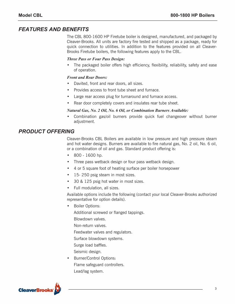
FEATURES AND BENEFITS The CBL 800-1600 HP Firetube boiler is designed, manufactured, and packaged byCleaver-Brooks. All units are factory fire tested and shipped as a package, ready forquick connection to utilities. In addition to the features provided on all Cleaver-Brooks Firetube boilers, the following features apply to the CBL.
Three Pass or Four Pass Design: • The packaged boiler offers high efficiency, flexibility, reliability, safety and ease
of operation.
Front and Rear Doors:• Davited, front and rear doors, all sizes.• Provides access to front tube sheet and furnace.• Large rear access plug for turnaround and furnace access.• Rear door completely covers and insulates rear tube sheet.
Natural Gas, No. 2 Oil, No. 6 Oil, or Combination Burners Available:• Combination gas/oil burners provide quick fuel changeover without burner
adjustment.
PRODUCT OFFERINGCleaver-Brooks CBL Boilers are available in low pressure and high pressure steamand hot water designs. Burners are available to fire natural gas, No. 2 oil, No. 6 oil,or a combination of oil and gas. Standard product offering is:• 800 - 1600 hp.• Three pass wetback design or four pass wetback design.• 4 or 5 square foot of heating surface per boiler horsepower• 15- 250 psig steam in most sizes.• 30 & 125 psig hot water in most sizes.• Full modulation, all sizes.Available options include the following (contact your local Cleaver-Brooks authorizedrepresentative for option details).• Boiler Options:
Additional screwed or flanged tappings.Blowdown valves.Non-return valves.Feedwater valves and regulators.Surface blowdown systems.Surge load baffles.Seismic design.
• Burner/Control Options:Flame safeguard controllers.Lead/lag system.

Model CBL 800-1800 HP Boilers
4
Special insurance and code requirements (e.g., IRI, FM, NFPA8501).Alarm bell/silence switch.Special motor requirements (TEFC, high efficiency).Special indicating lights.Main disconnect.Elapsed time meter.NEMA enclosures. Remote emergency shut-off (115V).Circuit breakers.Day/night controls.Special power requirements.Low NOx Equipment.HAWK ICS
• Fuel Options:Gas strainer.Gas pressure gauge.Future gas conversion.Oversized/undersized gas trains.Optional Oil Pumps.
DIMENSIONS AND RATINGS Dimensions and ratings for the CBL Boilers are shown in the following tables andillustrations. The information is subject to change without notice.
• Table A5-1. CBL Steam Boiler Ratings • Table A5-2. Heating Surface• Figure A5-1. CBL Steam Boiler Dimensions • Figure A5-2. CBL Boiler Space Requirements to Open Rear Door • Figure A5-3. Lifting Lug Location, CBL Boilers • Figure A5-4. CBL Boiler Mounting Piers

Model CBL 800-1800 HP Boilers
5
BOILER HP 800 900 1000 1100 1200 1300 1400 1500 1600
RATINGS - SEA LEVEL TO 1000 FT B
Rated Capacity (lbs-steam/hr from and at 212 °F) 27600 31050 34500 37950 41400 44850 48300 51750 55200
Btu Output (1000 Btu/hr) 26780 30128 33475 36823 40170 43518 46865 50213 53560
POWER REQUIREMENTS — SEA LEVEL TO 1000 FT ( 60 HZ)
Blower Motor hp A4 sq ft/BHP
3 pass - - 75 60 75 75 75 100
Contact Factory
4 pass - - 60 75 75 75 100 100
Blower Motor hp A5 sq ft/BHP
3 pass 60 75 75 60 75 75 75 100
4 pass 75 75 60 60 75 75 75 100
Oil Pump Motor hp (#2 oil) 1 1-1/2 1-1/2 1-1/2 1-1/2 1-1/2 1-1/2 1-1/2
Oil Pump Motor hp (#6 oil) 1 1 1 1 1 1 1 1-1/2
Air Comp. Motor, hp (#2 oil) 7-1/2 15 15 15 15 15 15 15
Oil heater Kw (#6 oil) 10 10 10 15 15 15 15 15NOTES: A. Blower motor HP may increase if a low NOx option is addedB. Ratings based on nominal 80% efficiency.C. Ratings based on 60 hertz, please verify 50 hertz ratings with factory.
Table A5-1. CBL Steam Boiler Ratings
Table A5-2. CBL Input Ratings (3-Pass Boilers)
Boiler Square Foot Heat-ing Surface
4000 4500 5000 5500 6000 6500 7000 7500
Approximate Fuel Consumption D
Horsepower(5 sq.ft./bhp)
800 900 1000 1100 1200 1300 1400 1500
Natural Gas A (cfh) 33475 37659 41844 46028 50213 54397 58581 62766
No. 2 Oil B (gph) 239.1 269.0 298.9 328.8 358.7 388.5 418.4 448.3
No. 6 Oil C (gph) 223.2 251.1 279.0 306.9 334.8 362.6 390.5 418.4
Horsepower(4 sq.ft./bhp)
1000 1100 1200 1300 1500 1600
Natural Gas A (cfh) 41844 46028 50213 54397 62766 66950
No. 2 Oil B (gph) 298.9 328.8 358.7 388.5 448.3 478.2
No. 6 Oil C(gph) 279.0 306.9 334.8 362.6 418.4 446.3
Notes:A. Natural gas based on heating value of 1000 BTU/cu.ftB. No. 2 oil based on heating value of 140,000 BTU/gal.C. No. 6 oil based on heating value of 150,000 BTU/gal.D. Ratings based on nominal 80% efficiency.
Model CBL 800-1800 HP Boilers
6
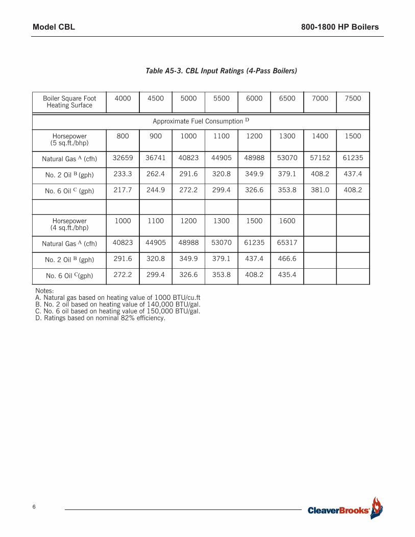
Boiler Square Foot Heating Surface
4000 4500 5000 5500 6000 6500 7000 7500
Approximate Fuel Consumption D
Horsepower(5 sq.ft./bhp)
800 900 1000 1100 1200 1300 1400 1500
Natural Gas A (cfh) 32659 36741 40823 44905 48988 53070 57152 61235
No. 2 Oil B (gph) 233.3 262.4 291.6 320.8 349.9 379.1 408.2 437.4
No. 6 Oil C (gph) 217.7 244.9 272.2 299.4 326.6 353.8 381.0 408.2
Horsepower(4 sq.ft./bhp)
1000 1100 1200 1300 1500 1600
Natural Gas A (cfh) 40823 44905 48988 53070 61235 65317
No. 2 Oil B (gph) 291.6 320.8 349.9 379.1 437.4 466.6
No. 6 Oil C(gph) 272.2 299.4 326.6 353.8 408.2 435.4
Notes:A. Natural gas based on heating value of 1000 BTU/cu.ftB. No. 2 oil based on heating value of 140,000 BTU/gal.C. No. 6 oil based on heating value of 150,000 BTU/gal.D. Ratings based on nominal 82% efficiency.
Table A5-3. CBL Input Ratings (4-Pass Boilers)
Model CBL 800-1800 HP Boilers
7
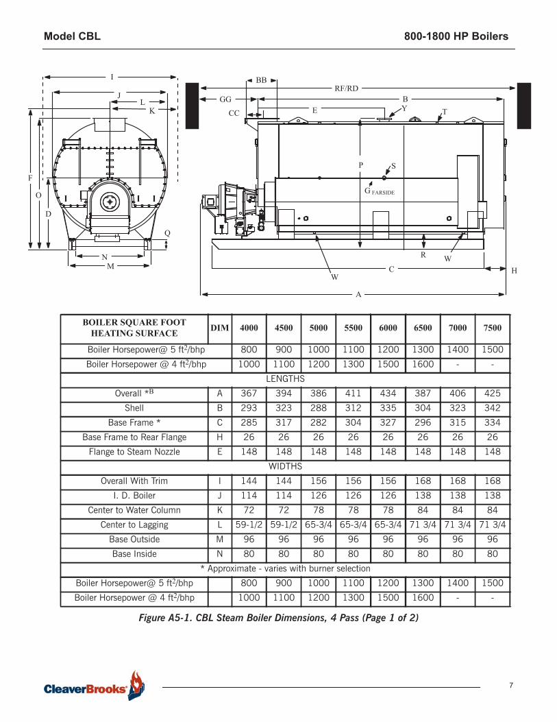
Figure A5-1. CBL Steam Boiler Dimensions, 4 Pass (Page 1 of 2)
A
B
C H
E
JL
MN
O
Q
GG
CC
BBRF/RD
Y T
S
R W
P
W
I
D
BOILER SQUARE FOOT HEATING SURFACE DIM 4000 4500 5000 5500 6000 6500 7000 7500
Boiler Horsepower@ 5 ft2/bhp 800 900 1000 1100 1200 1300 1400 1500
Boiler Horsepower @ 4 ft2/bhp 1000 1100 1200 1300 1500 1600 - -
LENGTHS
Overall *B A 367 394 386 411 434 387 406 425
Shell B 293 323 288 312 335 304 323 342
Base Frame * C 285 317 282 304 327 296 315 334
Base Frame to Rear Flange H 26 26 26 26 26 26 26 26
Flange to Steam Nozzle E 148 148 148 148 148 148 148 148
WIDTHS
Overall With Trim I 144 144 156 156 156 168 168 168
I. D. Boiler J 114 114 126 126 126 138 138 138
Center to Water Column K 72 72 78 78 78 84 84 84
Center to Lagging L 59-1/2 59-1/2 65-3/4 65-3/4 65-3/4 71 3/4 71 3/4 71 3/4
Base Outside M 96 96 96 96 96 96 96 96
Base Inside N 80 80 80 80 80 80 80 80
* Approximate - varies with burner selection
Boiler Horsepower@ 5 ft2/bhp 800 900 1000 1100 1200 1300 1400 1500
Boiler Horsepower @ 4 ft2/bhp 1000 1100 1200 1300 1500 1600 - -
F
K
G FARSIDE

Model CBL 800-1800 HP Boilers
8
HEIGHTS
Base to pipingconnections F 149 149 161 161 161 168-1/8 168-1/8 168-1/8
Base to Boiler Centerline D 77-1/2 77-1/2 83-3/4 83-3/4 83-3/4 86-1/2 86-1/2 86-1/2
Base to Vent Outlet O 141 141 153-1/2 153-1/2 153-1/2 162-1/8 162-1/8 162-1/8
Base to Steam Outlet P 141 141 153-1/2 153-1/2 153-1/2 162-1/8 162-1/8 162-1/8
Base Frame Q 12 12 12 12 12 12 12 12
Base to Bottom Boiler R 20 20 20 20 20 17 17 17
CONNECTIONS
Chemical Feed G 3/4 3/4 3/4 3/4 3/4 3/4 3/4 3/4
Feedwater Inlet (Both Sides) S 3 3 3 3 3 3 3 3
Steam NozzleA (150 psig) Y 10 10 10 12 12 12 12 12
Blowdown - Front & Rear W 2 2 2 2 2 2 2 2
Surface Blowoff T 1 1 1 1 1 1 1 1
Vent Stack Diameter (Flanged) BB 32 32 36 36 36 42 42 42
Flange to Center Vent CC 17-1/2 17-1/2 19-1/2 19-1/2 19-1/2 24 24 24
MISCELLANEOUS
Rear Door Swing c AA - - - - - - - -
Tube Removal - Front Only GG 246 276 217 241 264 233 252 271
Min. Boiler Room Length For Tube Removal Front RF 537 597 538 586 632 665 703 741
Min. Boiler Room Length For Tube Removal Thru Door RD 484 514 489 513 536 528 547 566
Normal Water Weight (Lbs) 43800 49400 49300 54000 60000 61000 66000 71000
Flooded Water Weight (Lbs) 54500 61300 65300 71900 78300 83000 89000 96000
Approx. Shipping Wt. 15/30 psig (Lbs.) 58000 63000 73100 77200 82200 87000 91700 96600
Approx. Shipping Wt. 150 psig (Lbs.) 65000 71000 79600 85300 90900 97300 102600 108200
Approx. Shipping Wt. 200 psig (Lbs.) 73500 82200 88600 95000 101500 107800 115500 121000
Approx. Shipping Wt. 250 psig (Lbs.) 81300 89000 97200 104000 110000 118000 124000 132000
NOTES: Accompanying dimensions, while sufficiently accurate for layout purposes, must be confirmed for actual option requirements.A. 300 psig Flange. See recommended steam nozzle size chart for operating pressure greater than 125 psig.B. Add 11 1/2 inches to dimension “B” for a three pass boiler.C. Reference Figure A11-2.
BOILER SQUARE FOOT HEATING SURFACE DIM 4000 4500 5000 5500 6000 6500 7000 7500
Figure A5-1. CBL Steam Boiler Dimensions, 4 Pass (Page 2 of 2)
Model CBL 800-1800 HP Boilers
9
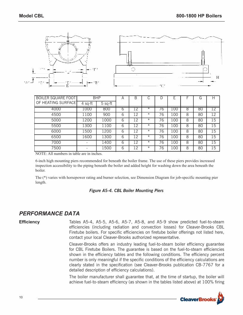
Figure A5-3. CBL Boilers Lifting Lug Location
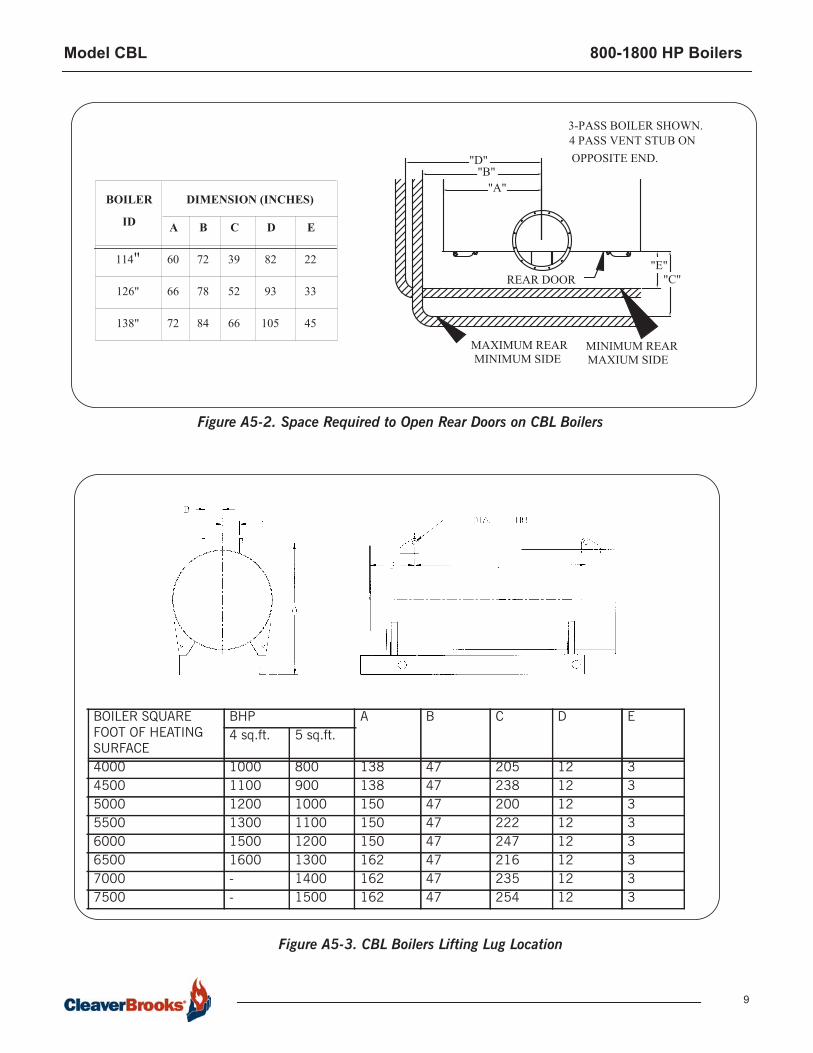
Figure A5-2. Space Required to Open Rear Doors on CBL Boilers
BOILER SQUARE FOOT OF HEATING SURFACE
BHP A B C D E4 sq.ft. 5 sq.ft.
4000 1000 800 138 47 205 12 34500 1100 900 138 47 238 12 35000 1200 1000 150 47 200 12 35500 1300 1100 150 47 222 12 36000 1500 1200 150 47 247 12 36500 1600 1300 162 47 216 12 37000 - 1400 162 47 235 12 37500 - 1500 162 47 254 12 3
"B""D"
"A"
"E""C"REAR DOOR
MINIMUM REARMAXIUM SIDE
MAXIMUM REARMINIMUM SIDE
BOILER
ID
114"
DIMENSION (INCHES)
A
126"
138"
60
66
72 84
72
78
B
66
39
52
C
105
82
93
D
45
22
33
E
3-PASS BOILER SHOWN. 4 PASS VENT STUB ONOPPOSITE END.
Model CBL 800-1800 HP Boilers
10
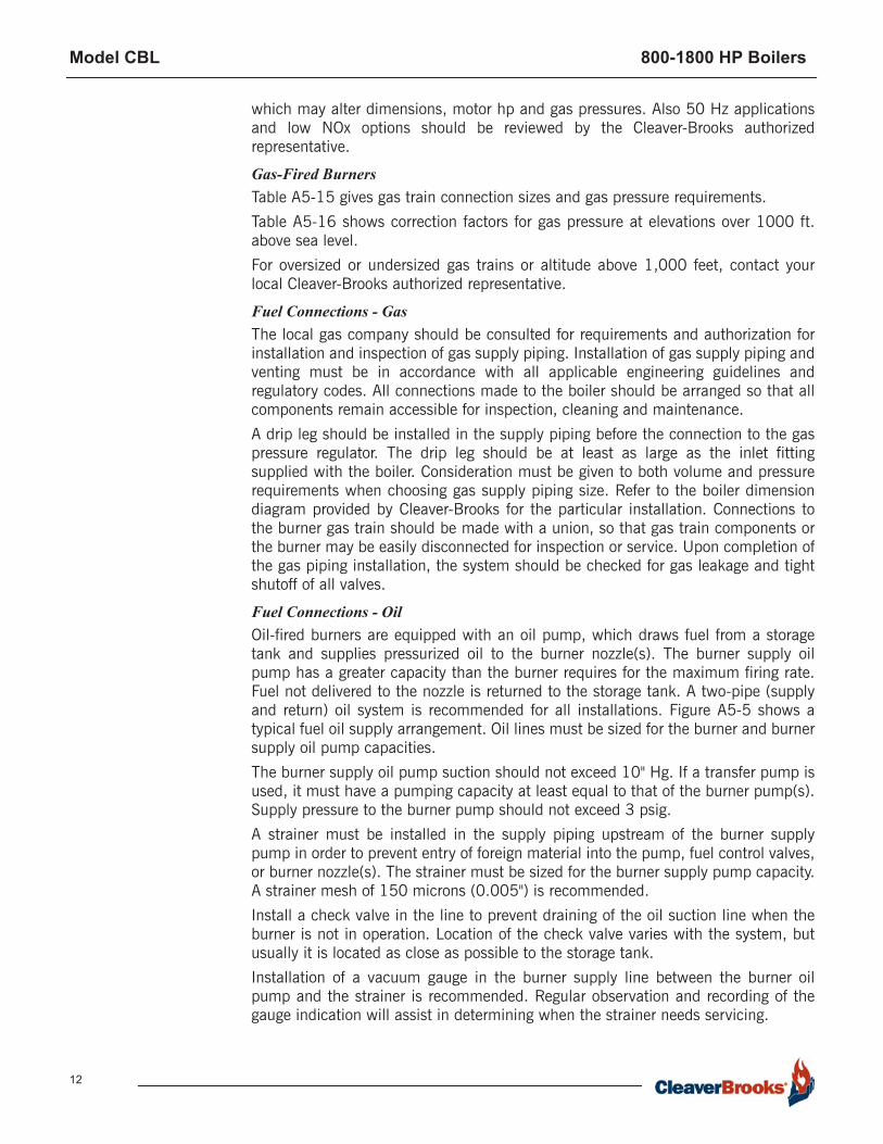
Figure A5-4. CBL Boiler Mounting Piers
E
BOILER SQUARE FOOT OF HEATING SURFACE
BHP A B C D E F G H4 sq-ft 5 sq-ft
4000 1000 800 6 12 * 76 100 8 80 124500 1100 900 6 12 * 76 100 8 80 125000 1200 1000 6 12 * 76 100 8 80 155500 1300 1100 6 12 * 76 100 8 80 156000 1500 1200 6 12 * 76 100 8 80 156500 1600 1300 6 12 * 76 100 8 80 157000 - 1400 6 12 * 76 100 8 80 157500 - 1500 6 12 * 76 100 8 80 15
NOTE: All numbers in table are in inches.
6-inch high mounting piers recommended for beneath the boiler frame. The use of these piers provides increased inspection accessibility to the piping beneath the boiler and added height for washing down the area beneath the boiler.
The (*) varies with horsepower rating and burner selection, see Dimension Diagram for job-specific mounting pier length.
H
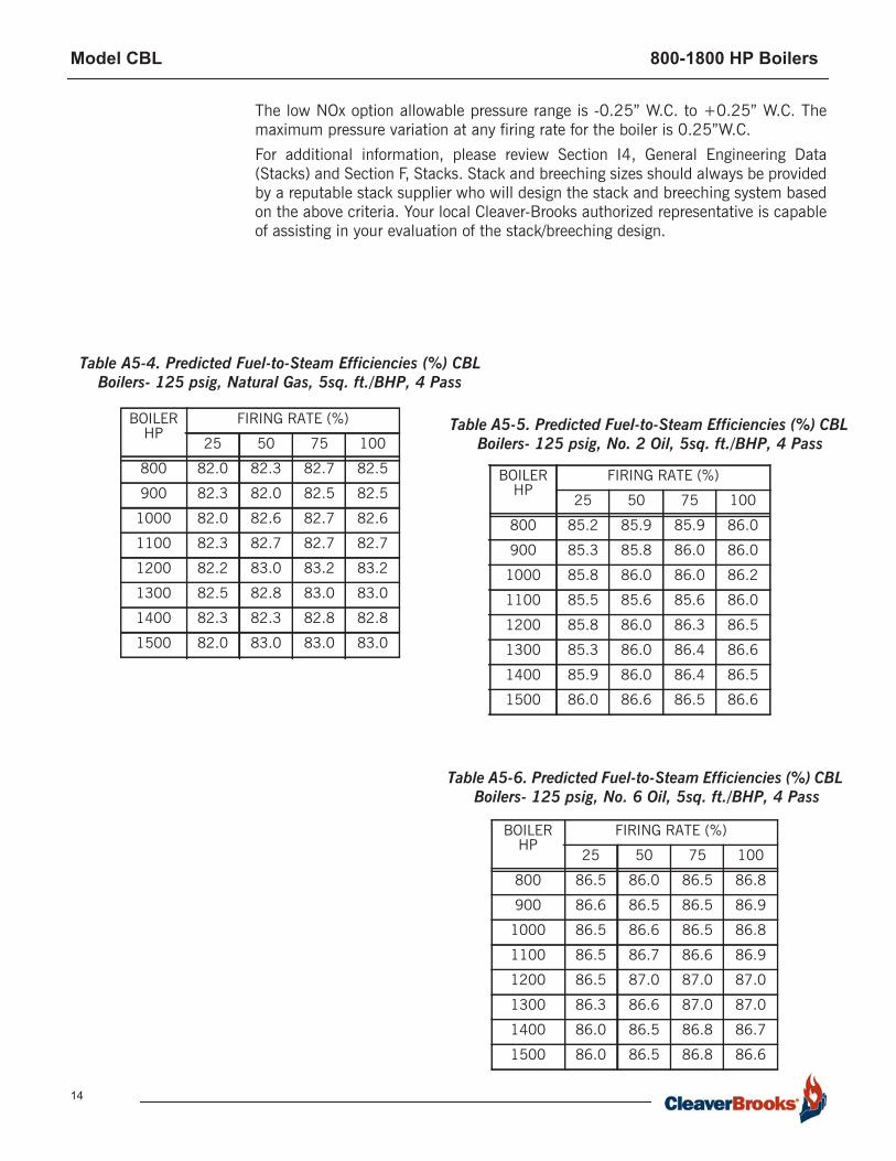
PERFORMANCE DATAEfficiency Tables A5-4, A5-5, A5-6, A5-7, A5-8, and A5-9 show predicted fuel-to-steam
efficiencies (including radiation and convection losses) for Cleaver-Brooks CBLFiretube boilers. For specific efficiencies on firetube boiler offerings not listed here,contact your local Cleaver-Brooks authorized representative.Cleaver-Brooks offers an industry leading fuel-to-steam boiler efficiency guaranteefor CBL Firetube Boilers. The guarantee is based on the fuel-to-steam efficienciesshown in the efficiency tables and the following conditions. The efficiency percentnumber is only meaningful if the specific conditions of the efficiency calculations areclearly stated in the specification (see Cleaver-Brooks publication CB-7767 for adetailed description of efficiency calculations).The boiler manufacturer shall guarantee that, at the time of startup, the boiler willachieve fuel-to-steam efficiency (as shown in the tables listed above) at 100% firing

Model CBL 800-1800 HP Boilers
11
rate (add efficiency guarantees at 25%, 50%, and 75% of rating, if required). If theboiler(s) fail to achieve the corresponding guaranteed efficiency as published, theboiler manufacturer will rebate, to the ultimate boiler owner, five thousand dollars($5,000) for every full efficiency point (1.0%) that the actual efficiency is below theguaranteed level. The specified boiler efficiency is based on the following conditions.1. Fuel specification used to determine boiler efficiency:
• Natural GasCarbon,% (wt) = 69.98Hydrogen,% (wt) = 22.31Sulfur,% (wt) = 0.0Heating value, Btu/lb = 21,830• No. 2 OilCarbon,% (wt) = 85.8Hydrogen,% (wt) = 12.7Sulfur,% (wt) = 0.2Heating value, Btu/lb = 19,420• No. 6 OilCarbon,% (wt) = 86.6Hydrogen,% (wt) = 10.9Sulfur,% (wt) = 2.09Heating value, Btu/lb = 18,830
2. Efficiencies are based on ambient air temperature of 80 °F, relative humidity of 30%, and 15% excess air in the exhaust flue gas.
3. Efficiencies are based on the following radiation and convection losses. Firing rate of 25% - 1.2%, 50% - 0.6%, 75% - 0.4%, and 100% - 0.3%.
ENGINEERING DATA The following engineering information is provided for CBL Boilers. Additional detailis available from your local Cleaver-Brooks authorized representative.
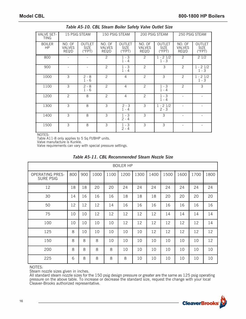
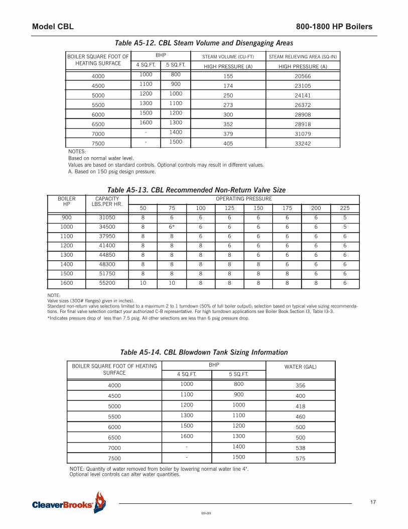
Boiler Information Table A5-12 shows steam volume and disengaging area for CBL boilers. Table A5-10 lists quantity and outlet size for safety valves supplied on CBL boilers. Table A5-11 gives recommended steam nozzle sizes on CBL Boilers. Table A5-13 shows recommended non-return valve sizes for CBL Boilers.Blowdown Water Requirements Some local codes require blowdown tanks to be constructed in accordance withrecommendations of the National Board of Boiler and Pressure Vessel Inspectors.The National Board’s recommendations base the size of the blowdown tank on theremoval of at least 4 inches of water from the boiler.Table A5-14 lists the approximate quantity of water represented by 4 inches ofwater at normal operating level for Cleaver-Brooks CBL Boilers.
Burner/Control Information
Burner Characteristics Note that altitude correction and burner changes are required for higher altitudes
Model CBL 800-1800 HP Boilers
12
which may alter dimensions, motor hp and gas pressures. Also 50 Hz applicationsand low NOx options should be reviewed by the Cleaver-Brooks authorizedrepresentative.
Gas-Fired BurnersTable A5-15 gives gas train connection sizes and gas pressure requirements.Table A5-16 shows correction factors for gas pressure at elevations over 1000 ft.above sea level.For oversized or undersized gas trains or altitude above 1,000 feet, contact yourlocal Cleaver-Brooks authorized representative.
Fuel Connections - Gas The local gas company should be consulted for requirements and authorization forinstallation and inspection of gas supply piping. Installation of gas supply piping andventing must be in accordance with all applicable engineering guidelines andregulatory codes. All connections made to the boiler should be arranged so that allcomponents remain accessible for inspection, cleaning and maintenance. A drip leg should be installed in the supply piping before the connection to the gaspressure regulator. The drip leg should be at least as large as the inlet fittingsupplied with the boiler. Consideration must be given to both volume and pressurerequirements when choosing gas supply piping size. Refer to the boiler dimensiondiagram provided by Cleaver-Brooks for the particular installation. Connections tothe burner gas train should be made with a union, so that gas train components orthe burner may be easily disconnected for inspection or service. Upon completion ofthe gas piping installation, the system should be checked for gas leakage and tightshutoff of all valves.
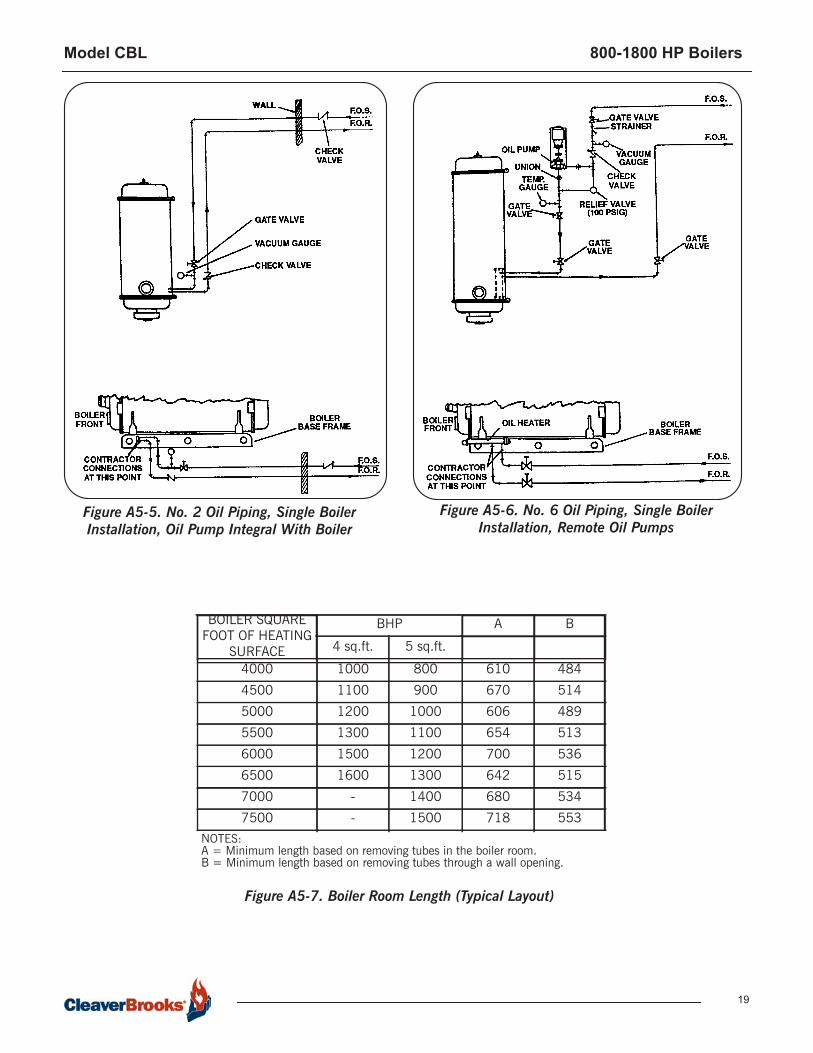
Fuel Connections - Oil Oil-fired burners are equipped with an oil pump, which draws fuel from a storagetank and supplies pressurized oil to the burner nozzle(s). The burner supply oilpump has a greater capacity than the burner requires for the maximum firing rate.Fuel not delivered to the nozzle is returned to the storage tank. A two-pipe (supplyand return) oil system is recommended for all installations. Figure A5-5 shows atypical fuel oil supply arrangement. Oil lines must be sized for the burner and burnersupply oil pump capacities.The burner supply oil pump suction should not exceed 10" Hg. If a transfer pump isused, it must have a pumping capacity at least equal to that of the burner pump(s).Supply pressure to the burner pump should not exceed 3 psig.A strainer must be installed in the supply piping upstream of the burner supplypump in order to prevent entry of foreign material into the pump, fuel control valves,or burner nozzle(s). The strainer must be sized for the burner supply pump capacity.A strainer mesh of 150 microns (0.005") is recommended. Install a check valve in the line to prevent draining of the oil suction line when theburner is not in operation. Location of the check valve varies with the system, butusually it is located as close as possible to the storage tank. Installation of a vacuum gauge in the burner supply line between the burner oilpump and the strainer is recommended. Regular observation and recording of thegauge indication will assist in determining when the strainer needs servicing.
Model CBL 800-1800 HP Boilers
13
Upon completion of the oil piping installation, the system should be checked for oilor air leakage and tight shutoff of all valves.
Boiler Room Information
Figure A5-7 shows typical boiler room length requirements.Figure A5-8 shows typical boiler room width requirements.
Stack Support Capabilities
CBL Boilers can support up to 2000 lbs. without additional support.CBL Boilers can be reinforced to support up to 3000 lbs.
Boiler Room Combustion Air
When determining boiler room air requirements, the size of the room, air flow, andvelocity of air must be reviewed as follows:1. Size (area) and location of air supply openings in boiler room.
A. Two (2) permanent air supply openings in the outer walls of the boiler room are recommended. Locate one (1) at each end of the boiler room, preferably below a height of 7 feet. This allows air to sweep the length of the boiler.
B.Air supply openings can be louvered for weather protection, but they should not be covered with fine mesh wire, as this type of covering has poor air flow qualities and is subject to clogging by dust or dirt.
C. A vent fan in the boiler room is not recommended, as it could create a slight vacuum under certain conditions and cause variations in the quantity of combustion air. This can result in unsatisfactory burner performance.
D.Under no condition should the total area of the air supply openings be less than one (1) square foot.
E. Size the openings by using the formula:
Area (sq-ft) = CFM/FPM2. Amount of air required (cfm).
A. Combustion Air = Rated bhp x 8 cfm/bhp. B.Ventilation Air = Maximum bhp x 2 cfm/bhp or a total of 10 cfm/bhp - up to 1000
feet elevation. Add 3 percent more per 1000 feet of added elevation. 3. Acceptable air velocity in Boiler Room (fpm).
A. From floor to (7) foot height - 250 fpm. B.Above (7) foot height - 500 fpm.
Example: Determine the area of the boiler room air supply openings for (1) 1000 hpboiler at 800 feet altitude. The air openings are to be 5 feet above floor level.• Air required: 1000 x 10 = 10000 cfm (from 2B above). • Air velocity: Up to 7 feet = 250 fpm (from 3 above). • Area Required: Area = cfm/fpm = 10000/250 = 40 Sq-ft total. • Area/Opening: 40/2 = 20 sq-ft/opening (2 required).
NoticeConsult local codes, which may supersede these requirements.
Stack/Breeching Size Criteria
The design of the stack and breeching must provide the required draft at each boilerflue gas outlet. Proper draft is critical to burner performance.Although constant pressure at the flue gas outlet of the CBL is not required, it isnecessary to size the stack/breeching to limit flue gas pressure variation. Theallowable pressure range is –0.50” W.C. to +0.50” W.C. The maximum pressurevariation at any firing rate for the boiler is 0.50" W.C.
Model CBL 800-1800 HP Boilers
14
The low NOx option allowable pressure range is -0.25” W.C. to +0.25” W.C. Themaximum pressure variation at any firing rate for the boiler is 0.25”W.C. For additional information, please review Section I4, General Engineering Data(Stacks) and Section F, Stacks. Stack and breeching sizes should always be providedby a reputable stack supplier who will design the stack and breeching system basedon the above criteria. Your local Cleaver-Brooks authorized representative is capableof assisting in your evaluation of the stack/breeching design.
BOILER HP
FIRING RATE (%)
25 50 75 100
800 82.0 82.3 82.7 82.5
900 82.3 82.0 82.5 82.5
1000 82.0 82.6 82.7 82.6
1100 82.3 82.7 82.7 82.7
1200 82.2 83.0 83.2 83.2
1300 82.5 82.8 83.0 83.0
1400 82.3 82.3 82.8 82.8
1500 82.0 83.0 83.0 83.0
Table A5-4. Predicted Fuel-to-Steam Efficiencies (%) CBL Boilers- 125 psig, Natural Gas, 5sq. ft./BHP, 4 Pass
BOILER HP
FIRING RATE (%)
25 50 75 100
800 85.2 85.9 85.9 86.0
900 85.3 85.8 86.0 86.0
1000 85.8 86.0 86.0 86.2
1100 85.5 85.6 85.6 86.0
1200 85.8 86.0 86.3 86.5
1300 85.3 86.0 86.4 86.6
1400 85.9 86.0 86.4 86.5
1500 86.0 86.6 86.5 86.6
Table A5-5. Predicted Fuel-to-Steam Efficiencies (%) CBL Boilers- 125 psig, No. 2 Oil, 5sq. ft./BHP, 4 Pass
BOILER HP
FIRING RATE (%)
25 50 75 100
800 86.5 86.0 86.5 86.8
900 86.6 86.5 86.5 86.9
1000 86.5 86.6 86.5 86.8
1100 86.5 86.7 86.6 86.9
1200 86.5 87.0 87.0 87.0
1300 86.3 86.6 87.0 87.0
1400 86.0 86.5 86.8 86.7
1500 86.0 86.5 86.8 86.6
Table A5-6. Predicted Fuel-to-Steam Efficiencies (%) CBL Boilers- 125 psig, No. 6 Oil, 5sq. ft./BHP, 4 Pass

Model CBL 800-1800 HP Boilers
15
BOILER HP
FIRING RATE (%)
25 50 75 100
1000 81.4 81.5 81.5 81.5
1100 81.3 81.6 82.0 82.0
1200 81.2 81.4 82.0 82.0
1300 81.0 81.3 81.6 82.0
1400 81.0 81.3 81.4 81.8
1500 81.0 81.4 81.4 81.9
Table A5-7. Predicted Fuel-to-Steam Efficiencies (%) CBL Boilers- 125 psig, Natural Gas, 4 sq. ft./BHP, 3 Pass
BOILER HP
FIRING RATE (%)
25 50 75 100
1000 84.8 85.0 85.0 85.0
1100 84.7 85.0 85.0 85.0
1200 85.0 85.2 85.4 85.2
1300 85.0 85.0 84.8 85.5
1400 85.0 85.6 84.8 85.5
1500 85.0 85.5 84.9 85.6
Table A5-8. Predicted Fuel-to-Steam Efficiencies (%) CBL Boilers- 125 psig, No. 2 Oil, 4 sq. ft./BHP, 3 Pass
BOILER HP
FIRING RATE (%)
25 50 75 100
1000 86.2 86.2 85.8 85.6
1100 86.3 86.4 86.1 85.9
1200 86.2 86.2 85.8 86.0
1300 86.0 86.4 86.1 85.8
1400 86.0 86.4 86.0 85.8
1500 86.0 86.3 86.2 85.9
Table A5-9. Predicted Fuel-to-Steam Efficiencies (%) CBL Boilers- 125 psig, No. 6 Oil, 4 sq. ft./BHP, 3 Pass
Model CBL 800-1800 HP Boilers
16
BOILER HP
OPERATING PRES-SURE PSIG
800 900 1000 1100 1200 1300 1400 1500 1600 1700 1800
12 18 18 20 20 24 24 24 24 24 24 24
30 14 16 16 16 18 18 18 20 20 20 20
50 12 12 12 14 16 16 16 16 16 16 16
75 10 10 12 12 12 12 12 14 14 14 14
100 10 10 10 10 12 12 12 12 12 12 14
125 8 10 10 10 10 10 12 12 12 12 12
150 8 8 8 10 10 10 10 10 10 10 12
200 8 8 8 8 10 10 10 10 10 10 10
225 6 8 8 8 8 10 10 10 10 10 10
NOTES: Steam nozzle sizes given in inches.All standard steam nozzle sizes for the 150 psig design pressure or greater are the same as 125 psig operating pressure on the above table. To increase or decrease the standard size, request the change with your local Cleaver-Brooks authorized representative.
VALVE SET-TING
15 PSIG STEAM 150 PSIG STEAM 200 PSIG STEAM 250 PSIG STEAM
BOILERHP
NO. OF VALVES REQ'D
OUTLET SIZE
(“FPT)
NO. OF VALVES REQ'D
OUTLET SIZE
(“FPT)
NO. OF VALVES REQ'D
OUTLET SIZE
(“FPT)
NO. OF VALVES REQ'D
OUTLET SIZE
(“FPT)
800 - - 2 1 - 31 - 4
2 1 - 2 1/21 - 3
2 2 1/2
900 - - 2 1 - 31 - 4
2 3 2 1 - 2 1/21 - 3
1000 3 2 - 81 - 6
2 4 2 3 2 1 - 2 1/21 - 3
1100 3 2 - 81 - 6
2 4 2 1 - 31 - 4
2 3
1200 2 8 2 4 2 1 - 31 - 4
- -
1300 3 8 3 2 - 31 - 4
3 1 - 2 1/22 - 3
- -
1400 3 8 3 1 - 32 - 4
3 3 - -
1500 3 8 3 1 - 32 - 4
3 3 - -
NOTES: Table A11-8 only applies to 5 Sq Ft/BHP units.Valve manufacture is Kunkle.Valve requirements can vary with special pressure settings.
Table A5-10. CBL Steam Boiler Safety Valve Outlet Size
Table A5-11. CBL Recommended Steam Nozzle Size
Model CBL 800-1800 HP Boilers
17
BOILER SQUARE FOOT OF HEATING SURFACE
BHP WATER (GAL)4 SQ.FT. 5 SQ.FT.
4000 1000 800 356
4500 1100 900 400
5000 1200 1000 418
5500 1300 1100 460
6000 1500 1200 500
6500 1600 1300 500
7000 - 1400 538
7500 - 1500 575
NOTE: Quantity of water removed from boiler by lowering normal water line 4".Optional level controls can alter water quantities.
NOTE: Valve sizes (300# flanges) given in inches).Standard non-return valve selections limited to a maximum 2 to 1 turndown (50% of full boiler output); selection based on typical valve sizing recommenda-tions. For final valve selection contact your authorized C-B representative. For high turndown applications see Boiler Book Section I3, Table I3-3.*Indicates pressure drop of less than 7.5 psig. All other selections are less than 6 psig pressure drop.
BOILER HP
CAPACITYLBS.PER HR.
OPERATING PRESSURE
50 75 100 125 150 175 200 225
900 31050 8 6 6 6 6 6 6 5
1000 34500 8 6* 6 6 6 6 6 5
1100 37950 8 8 6 6 6 6 6 6
1200 41400 8 8 8 6 6 6 6 6
1300 44850 8 8 8 8 6 6 6 6
1400 48300 8 8 8 8 8 6 6 6
1500 51750 8 8 8 8 8 8 6 6
1600 55200 10 10 8 8 8 8 8 6
BOILER SQUARE FOOT OF HEATING SURFACE
BHP STEAM VOLUME (CU-FT) STEAM RELIEVING AREA (SQ-IN)
4 SQ.FT. 5 SQ.FT. HIGH PRESSURE (A) HIGH PRESSURE (A)
4000 1000 800 155 20566
4500 1100 900 174 23105
5000 1200 1000 250 24141
5500 1300 1100 273 26372
6000 1500 1200 300 28908
6500 1600 1300 352 28918
7000 - 1400 379 31079
7500 - 1500 405 33242
Table A5-12. CBL Steam Volume and Disengaging Areas
09-09
NOTES:Based on normal water level.Values are based on standard controls. Optional controls may result in different values.A. Based on 150 psig design pressure.
Table A5-14. CBL Blowdown Tank Sizing Information
Table A5-13. CBL Recommended Non-Return Valve Size

Model CBL 800-1800 HP Boilers
18
ALTITUDE (FT) CORRECTION FACTOR ALTITUDE (FT) CORRECTION FACTOR
1000 1.04 6000 1.25
2000 1.07 7000 1.30
3000 1.11 8000 1.35
4000 1.16 9000 1.40
5000 1.21 - -
To obtain minimum required gas pressure at altitudes above 700 feet, multiply the pressure by the list-ed factors: inches WC x 0.577 = oz/sq-in. oz/sq-in x 1.732 = inches WC.inches WC x 0.0361= psig. oz/sq-in x 0.0625 = psig.psig x 27.71 = Inches WC. psig x 16.0 = oz/sq-in.
Table A5-16. Altitude Correction for Gas
Table A5-15. CBL gas train connection size and gas pressure requirements
Model CBL 800-1800 HP Boilers
19
Figure A5-5. No. 2 Oil Piping, Single Boiler Installation, Oil Pump Integral With Boiler
Figure A5-6. No. 6 Oil Piping, Single Boiler Installation, Remote Oil Pumps
BOILER SQUARE FOOT OF HEATING
SURFACE
BHP A B
4 sq.ft. 5 sq.ft.
4000 1000 800 610 484
4500 1100 900 670 514
5000 1200 1000 606 489
5500 1300 1100 654 513
6000 1500 1200 700 536
6500 1600 1300 642 515
7000 - 1400 680 534
7500 - 1500 718 553NOTES: A = Minimum length based on removing tubes in the boiler room.B = Minimum length based on removing tubes through a wall opening.
Figure A5-7. Boiler Room Length (Typical Layout)
Model CBL 800-1800 HP Boilers
20
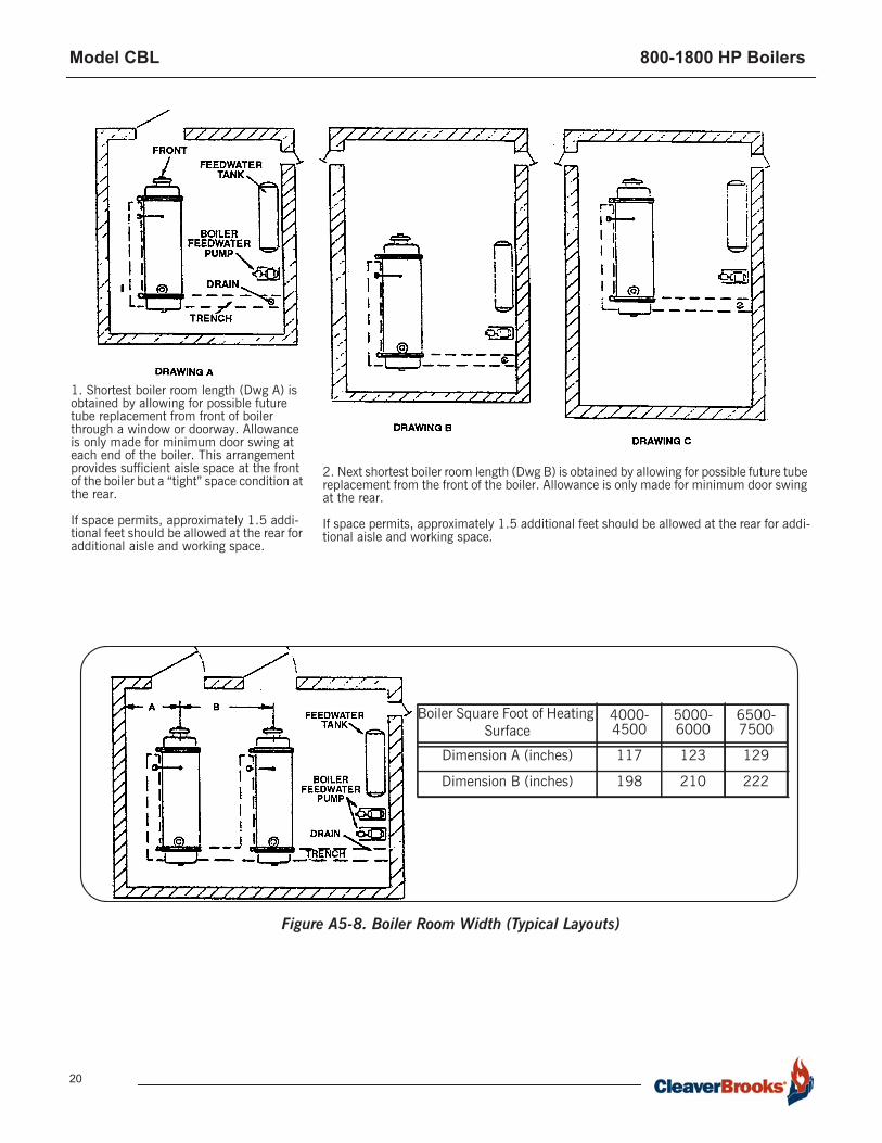
1. Shortest boiler room length (Dwg A) is obtained by allowing for possible future tube replacement from front of boiler through a window or doorway. Allowance is only made for minimum door swing at each end of the boiler. This arrangement provides sufficient aisle space at the front of the boiler but a “tight” space condition at the rear.
If space permits, approximately 1.5 addi-tional feet should be allowed at the rear for additional aisle and working space.
2. Next shortest boiler room length (Dwg B) is obtained by allowing for possible future tube replacement from the front of the boiler. Allowance is only made for minimum door swing at the rear.
If space permits, approximately 1.5 additional feet should be allowed at the rear for addi-tional aisle and working space.
Boiler Square Foot of Heating Surface
4000-4500
5000-6000
6500-7500
Dimension A (inches) 117 123 129
Dimension B (inches) 198 210 222
Figure A5-8. Boiler Room Width (Typical Layouts)