model dlw400esa4service.multiquip.com/pdfs/dlw400esa4-rev-0-op.pdf · dlw400esa4 welder/generator...
TRANSCRIPT

TM
OPERATION MANUAL
THIS MANUAL MUST ACCOMPANY THE EQUIPMENT AT ALL TIMES.
To find the latest revision of this publication, visit our website at:
www.multiquip.com
MODEL DLW400ESA4WELDER/GENERATOR
(KUBOTA D902E4BWDDE2 DIESEL ENGINE)
Revision #0 (03/14/18)

PAGE 2 — DLW400ESA4 WELDER/GENERATOR • OPERATION MANUAL — REV. #0 (03/14/18)
PROPOSITION 65 WARNING
Diesel engine exhaust and some of

DLW400ESA4 WELDER/GENERATOR • OPERATION MANUAL — REV. # 0 (03/14/18) — PAGE 3
REPORTING SAFETY DEFECTS
If you believe that your vehicle has a defect that could cause a crash or could cause injury or death, you should immediately inform the National Highway Traffi c Safety Administration (NHTSA) in addition to notifying Multiquip Inc. at 1-800-421-1244.
If NHTSA receives similar complaints, it may open an investigation, and if it fi nds that a safety defect exists in a group of vehicles, it may order a recall and remedy campaign. However, NHTSA cannot become involved in individual problems between you, your dealer, or Multiquip Inc.
To contact NHTSA, you may either call the Vehicle Safety Hotline toll-free at 1-888-327-4236 (TTY: 1-800-424-9153), go to http://www.safercar.gov; or write to:
AdministratorNHTSA1200 New Jersey Avenue, SEWashington, DC 20590
You can also obtain information about motor vehicle safety from http://www.safercar.gov.

PAGE 4 — DLW400ESA4 WELDER/GENERATOR • OPERATION MANUAL — REV. #0 (03/14/18)
TABLE OF CONTENTS
DLW400ESA4 Welder-GeneratorProposition 65 Warning ........................................... 2Reporting Safety Defects ......................................... 3Table Of Contents .................................................... 4Parts Ordering Procedures ...................................... 5Safety Information .............................................. 6-13Specifications ........................................................ 14Specifications (Fuel Consumption) ........................ 15Dimensions ............................................................ 16Installation ........................................................ 18-19General Information ............................................... 20Welding Polarity And Duty Cycle ........................... 21Welding Terms ....................................................... 22Components (Welder/Generator) ..................... 23-24Components (Engine) ............................................ 25Power Receptacles ................................................ 26Control Panel .................................................... 27-28Inspection ......................................................... 29-30Inspection/Setup .................................................... 31Setup ................................................................ 32-33Operation .......................................................... 34-41Maintenance ..................................................... 42-51Generator Wiring Diagram ..................................... 52Generator Wiring Diagram (Reference Designators) .. 53Engine Wiring Diagram .......................................... 54Error Codes ........................................................... 55Troubleshooting ................................................ 56-58
NOTICE
Specifications are subject to change without notice.

DLW400ESA4 WELDER/GENERATOR • OPERATION MANUAL — REV. # 0 (03/14/18) — PAGE 5
PARTS ORDERING PROCEDURES
ww
w.m
ultiq
uip
.com
Ordering parts has never been easier! Choose from three easy options:
WE ACCEPT ALL MAJOR CREDIT CARDS!
When ordering parts, please supply:❒ Dealer Account Number❒ Dealer Name and Address❒ Shipping Address (if different than billing address)❒ Return Fax Number❒ Applicable Model Number❒ Quantity, Part Number and Description of Each Part
❒ Specify Preferred Method of Shipment: ✓ UPS/Fed Ex ✓ DHL ■ Priority One ✓ Truck ■ Ground ■ Next Day ■ Second/Third Day
If you have an MQ Account, to obtain a Username and Password, E-mail us at: [email protected].
To obtain an MQ Account, contact your District Sales Manager for more information.
Order via Internet (Dealers Only):Order parts on-line using Multiquip’s SmartEquip website! ■ View Parts Diagrams ■ Order Parts ■ Print Specification Information
Note: Discounts Are Subject To Change
Goto www.multiquip.com and click on Order Parts to log in and save!
Use the internet and qualify for a 5% Discount on Standard orders for all orders which include complete part numbers.*
Order via Fax (Dealers Only):All customers are welcome to order parts via Fax.Domestic (US) Customers dial: 1-800-6-PARTS-7 (800-672-7877)
Fax your order in and qualify for a 2% Discount on Standard orders for all orders which include complete part numbers.*
Order via Phone: Domestic (US) Dealers Call: 1-800-427-1244
Best Deal!
International Customers should contact their local Multiquip Representatives for Parts Ordering information.
Non-Dealer Customers: Contact your local Multiquip Dealer for parts or call 800-427-1244 for help in locating a dealer near you.
Note: Discounts Are Subject To Change
Effective: January 1st, 2006
NOTICE
All orders are treated as Standard Orders and will ship the same day if received prior to 3PM PST.

PAGE 6 — DLW400ESA4 WELDER/GENERATOR • OPERATION MANUAL — REV. #0 (03/14/18)
SAFETY INFORMATION
DO NOT operate or service the equipment before reading the entire manual. Safety precautions should be followed at all times when operating this equipment. Failure to read and understand the safety messages and operating instructions could result in injury to yourself and others.
SAFETY MESSAGES
The four safety messages shown below will inform you about potential hazards that could injure you or others. The safety messages specifi cally address the level of exposure to the operator and are preceded by one of four words: DANGER, WARNING, CAUTION or NOTICE.
SAFETY SYMBOLS
DANGER
Indicates a hazardous situation which, if not avoided, WILL result in DEATH or SERIOUS INJURY.
WARNING
Indicates a hazardous situation which, if not avoided, COULD result in DEATH or SERIOUS INJURY.
CAUTION
Indicates a hazardous situation which, if not avoided, COULD result in MINOR or MODERATE INJURY.
NOTICE
Addresses practices not related to personal injury.
Potential hazards associated with the operation of this equipment will be referenced with hazard symbols which may appear throughout this manual in conjunction with safety messages.
Lethal Exhaust Gas Hazards
Explosive Fuel Hazards
Burn Hazards
Symbol Safety Hazard
Welding Hazards
EMF Hazards
Fire Hazards
Electric Shock Hazards
Pacemaker Hazards
Implant Hazards
Flying Sparks Hazards

DLW400ESA4 WELDER/GENERATOR • OPERATION MANUAL — REV. # 0 (03/14/18) — PAGE 7
SAFETY INFORMATION
GENERAL SAFETY
CAUTION
�NEVER operate this equipment without proper protective clothing, shatterproof glasses, respiratory protection, hearing protection, steel-toed boots and other protective devices required by the job or city and state regulations.
�NEVER operate this equipment when not feeling well due to fatigue, illness or when under medication.
�NEVER operate this equipment under the infl uence of drugs or alcohol.
NOTICE
� This equipment should only be operated by trained and qualifi ed personnel 18 years of age and older.
�Whenever necessary, replace nameplate, operation and safety decals when they become diffi cult read.
�Manufacturer does not assume responsibility for any accident due to equipment modifi cations. Unauthorized equipment modifi cation will void all warranties.
�NEVER use accessories or attachments that are not recommended by Multiquip for this equipment. Damage to the equipment and/or injury to user may result.
�ALWAYS know the location of the nearest fi re extinguisher.
�ALWAYS know the location of the nearest fi rst aid kit.
�ALWAYS know the location of the nearest phone or keep a phone on the job site. Also, know the phone numbers of the nearest ambulance, doctor and fi re department. This information will be invaluable in the case of an emergency.

PAGE 8 — DLW400ESA4 WELDER/GENERATOR • OPERATION MANUAL — REV. #0 (03/14/18)
SAFETY INFORMATION
WELDER SAFETY
DANGER
�NEVER install or operate the welder-generator in an explosive atmosphere or near combustible materials. An explosion or fi re could result causing severe bodily harm or even death.
� Flying sparks can cause injury. Wear a face shield to protect eyes and face.
�Remove all fl ammables within 35 ft (10.7 m) of welding arc. If this is not possible, tightly cover them with approved covers.
�Do not weld where fl ying sparks can strike fl ammable material.
�Hot metal from air arc cutting and gouging can cause fi re or explosion. DO NOT cut or gouge near fl ammables.
�Welding on closed containers, like tanks, drums or pipes, can cause them to blow up. DO NOT weld on closed containers unless they are properly prepared according to AWS F4.1 (see Recommended Safe Practices for the Preparation for Welding and Cutting of Containers and Piping from American Welding Society Standards). Check and be sure area is safe before doing any welding.
�Protect yourself and others from fl ying sparks and hot metal. Wear oil-free protective garments like leather gloves, heavy shirt, cuffl ess trousers, high shoes and a cap.
�Be alert that welding sparks and hot materials from welding can go through small cracks and openings to adjacent areas.
�Be aware that welding on a ceiling, fl oor, bulkhead or partition can cause fi re on hidden side.
�Connect welding cable to the work as close to welding area as practical to prevent welding current from traveling long, possibly unknown paths and causing electric shock, sparks and fi re hazards.
�DO NOT use welder-generator to thaw frozen pipes.
�Remove stick electrode from holder or cut off welding wire at contact tip when not in use.
�DO NOT touch output terminals during operation. Contact with output terminals during operation can cause electrocution, electrical shock or burn.
�Remove any combustibles, such as a butane lighter or matches, from your person before doing any welding.
�After completion of work, inspect area to ensure it is free of sparks, glowing embers and fl ames.
� Follow requirements in OSHA 1910.252 (a) (2) (iv) and NFPA 51B for hot work and have a fi re watcher and extinguisher nearby.
WARNING
�Keep your head out of the fumes. Use enough ventilation or exhaust at the arc, or both, to keep the fumes and gases from your breathing zone and the general area. In a large room or outdoors, natural ventilation may be adequate if you keep your head out of the fumes.
�DO NOT get too close to the arc. Use corrective lenses if necessary to stay a reasonable distance away from the arc.
�Use natural drafts or fans to keep the fumes away from your face.
�Welding wire can cause injury. Do not press gun trigger until instructed to do so. Do not point gun toward any part of the body, other people or any metal when threading welding wire.
�Have only qualified people remove doors, panels, covers or guards for maintenance and troubleshooting if necessary.
�Reinstall doors, panels, covers or guards when servicing is fi nished and before starting engine.
�NEVER disconnect any emergency or safety devices. These devices are intended for operator safety. Disconnection of these devices can cause severe injury, bodily harm or even death. Disconnection of any of these devices will void all warranties.

DLW400ESA4 WELDER/GENERATOR • OPERATION MANUAL — REV. # 0 (03/14/18) — PAGE 9
SAFETY INFORMATION
CAUTION
�Electric current flowing through any conductor causes localized Electro Magnetic Fields (EMF). Welding current creates EMF fi elds around welding cables and welding machines.
�Wearers of pacemakers and other implanted medical devices should keep away from welding equipment when in use.
� Implanted medical device wearers should consult their doctor and the device manufacturer before going near arc welding, spot welding, gouging, plasma arc cutting or induction heating operations.
�Exposure to EMF fi elds in welding may have other health effects which are now not known.
�All welders should use the following procedures in order to minimize exposure to EMF fi elds from the welding circuit:
• Route the electrode and work cables together. Secure them with tape when possible.
• NEVER coil the electrode lead around your body.
• DO NOT place your body between the electrode and work cables. If the electrode cable is on your right side, the work cable should also be on your right side.
• Connect the work cable to the workpiece as close as possible to the area being welded.
• DO NOT work next to the welder-generator.
NOTICE
�Electromagnetic energy can interfere with sensitive electronic equipment such as microprocessors, computers and computer-driven equipment such as robots. Be sure all equipment in the welding area is electromagnetically compatible.
To reduce possible interference, keep weld cables as short as possible, close together and down low, such as on the fl oor. Locate welding operation 100 meters from any sensitive electronic equipment. Be sure welder-generator is installed and grounded according to this manual.
If interference still occurs, the operator must take extra measures, like moving the welder-generator, using shielded cables, using line fi lters or shielding the work area.
�NEVER lubricate components or attempt service on a running machine.
�Overheating can damage equipment. Turn off or unplug equipment before starting or stopping engine. Low voltage and frequency caused by low engine speed can damage electric devices. Ensure engine speed is correct during operation.
�Overloading shortens the life of the welder-generator. Use the machine with appropriate AC and DC current and appropriate duty cycle.
�ALWAYS ensure welder-generator is on level ground before use.
�ALWAYS keep the welder-generator in proper running condition.
� Fix damage to welder-generator and replace any broken parts immediately.
�ALWAYS store welder-generator properly when it is not being used. Equipment should be stored in a clean, dry location out of the reach of children and unauthorized personnel.

PAGE 10 — DLW400ESA4 WELDER/GENERATOR • OPERATION MANUAL — REV. #0 (03/14/18)
SAFETY INFORMATION
ENGINE SAFETY
DANGER
� The engine fuel exhaust gases contain poisonous carbon monoxide. This gas is colorless and odorless, and can cause death if inhaled.
� The engine of this equipment requires an adequate free fl ow of cooling air. NEVER operate this equipment in any enclosed or narrow area where free fl ow of the air is restricted. If the air fl ow is restricted it will cause injury to people and property and serious damage to the equipment or engine.
WARNING
�DO NOT place hands or fingers inside engine compartment when engine is running.
�NEVER operate the engine with heat shields or guards removed.
�Keep fi ngers, hands, hair and clothing away from all moving parts to prevent injury.
�DO NOT remove the radiator cap or coolant drain plug while the engine is hot. High pressure boiling water or coolant will gush out and severely scald any persons in the general area of the welder-generator.
�DO NOT remove the engine oil drain plug while the engine is hot. Hot oil will gush out of the engine crankcase and severely scald any persons in the general area of the welder-generator.
CAUTION
�NEVER touch the hot exhaust manifold, muffl er or cylinder. Allow these parts to cool before servicing equipment.
NOTICE
�NEVER run engine without an air fi lter or with a dirty air fi lter. Severe engine damage may occur. Service air fi lter frequently to prevent engine malfunction.
�NEVER tamper with the factory settings of the engine or engine governor. Damage to the engine or equipment can result if operating in speed ranges above the maximum allowable.
�State Health Safety Codes and Public Resources Codes specify that in certain locations, spark arresters must be used on internal combustion engines that use hydrocarbon fuels. A spark arrester is a device designed to prevent accidental discharge of sparks or fl ames from the engine exhaust. Spark arresters are qualifi ed and rated by the United States Forest Service for this purpose. In order to comply with local laws regarding spark arresters, consult the engine distributor or the local Health and Safety Administrator.
�Wet stacking is a common problem with diesel engines which are operated for extended periods with light or no load applied. When a diesel engine operates without suffi cient load (less than 40% of the rated output), it will not operate at its optimum temperature. This will allow unburned fuel to accumulate in the exhaust system, which can foul the fuel injectors, engine valves and exhaust system, including turbochargers, and reduce the operating performance.
In order for a diesel engine to operate at peak effi ciency, it must be able to provide fuel and air in the proper ratio and at a high enough engine temperature for the engine to completely burn all of the fuel.
Wet stacking does not usually cause any permanent damage and can be alleviated if additional load is applied to relieve the condition. It can reduce the system performance and increase maintenance. Applying an increasing load over a period of time until the excess fuel is burned off and the system capacity is reached usually can repair the condition. This can take several hours to burn off the accumulated unburned fuel.

DLW400ESA4 WELDER/GENERATOR • OPERATION MANUAL — REV. # 0 (03/14/18) — PAGE 11
SAFETY INFORMATION
FUEL SAFETY
DANGER
�DO NOT add fuel to equipment if it is placed inside truck bed with plastic liner. Possibility exists of explosion or fi re due to static electricity.
�DO NOT start the engine near spilled fuel or combustible fl uids. Gasoline fuel is extremely fl ammable and its vapors can cause an explosion if ignited.
�ALWAYS refuel in a well-ventilated area, away from sparks and open fl ames.
�ALWAYS use extreme caution when working with fl ammable liquids.
�DO NOT fi ll the fuel tank while the engine is running or hot.
�DO NOT overfi ll tank, since spilled fuel could ignite if it comes into contact with hot engine parts or sparks from the ignition system.
�Store fuel in appropriate containers, in well-ventilated areas and away from sparks and fl ames.
�NEVER use fuel as a cleaning agent.
�DO NOT smoke around or near the equipment. Fire or explosion could result from fuel vapors or if fuel is spilled on a hot engine
ELECTRICAL SAFETY
DANGER
� Turn welder-generator and all circuit breakers OFF before performing maintenance on the generator or making contact with output receptacles.
�NEVER insert any objects into the output receptacles during operation. This is extremely dangerous. The possibility exists of electrical shock, electrocution or death.
�Backfeed to a utility system can cause electrocution and/or property damage. NEVER connect the welder-generator to a building’s electrical system without a transfer switch or other approved device. All installations should be performed by a licensed electrician in accordance with all applicable laws and electrical codes. Failure to do so could result in electrical shock or burn, causing serious injury or even death.
Power Cord/Cable Safety
DANGER
�NEVER let power cords or cables lay in water.
�NEVER stand in water while AC or DC power from the generator is being transferred to a load.
�NEVER use damaged or worn cables or cords when connecting equipment to generator. Inspect for cuts in the insulation.
�NEVER grab or touch a live power cord or cable with wet hands. The possibility exists of electrical shock, electrocution or death.
�Make sure power cables are securely connected to the generator’s output receptacles. Incorrect connections may cause electrical shock and damage to the generator.
NOTICE
�ALWAYS make certain that proper power or extension cord has been selected for the job. See Cable Selection Chart in this manual.

PAGE 12 — DLW400ESA4 WELDER/GENERATOR • OPERATION MANUAL — REV. #0 (03/14/18)
SAFETY INFORMATION
Grounding Safety
DANGER
� These welder-generators are equipped with a grounding terminal at the base of the pipe frame. Electrical grounding requirements can differ by State, Province, District, Municipality, and unique application settings.
� For portable and vehicle-mounted welder-generators, Multiquip recognizes the guidance provided in NEC Handbook Article 250.34 Parts A and B, and 29 CFR 1926.404 (f) (3) (i). If a more defi nitive earth-to-ground safeguard is required, please consult a qualified electrician and reference appropriate National Electrical Code (NEC) guidelines in establishing an exterior grounding point
�NEVER use gas piping as an electrical ground.
BATTERY SAFETY DANGER
�DO NOT drop the battery. There is a possibility that the battery will explode.
�DO NOT expose the battery to open fl ames, sparks, cigarettes, etc. The battery contains combustible gases and liquids. If these gases and liquids come into contact with a fl ame or spark, an explosion could occur.
�DO NOT charge battery if frozen. Battery can explode. When frozen, warm the battery to at least 61°F (16°C)
WARNING
�ALWAYS wear safety glasses when handling the battery to avoid eye irritation. The battery contains acids that can cause injury to the eyes and skin.
�Use well-insulated gloves when picking up the battery.
�ALWAYS keep the battery charged. If the battery is not charged, combustible gas will build up.
�ALWAYS recharge the battery in a well-ventilated environment to avoid the risk of a dangerous concentration of combustible gasses.
� If the battery liquid (dilute sulfuric acid) comes into contact with clothing or skin, rinse skin or clothing immediately with plenty of water.
� If the battery liquid (dilute sulfuric acid) comes into contact with eyes, rinse eyes immediately with plenty of water and contact the nearest doctor or hospital to seek medical attention.
CAUTION
�ALWAYS disconnect the NEGATIVE battery terminal before performing service on the generator.
�ALWAYS keep battery cables in good working condition. Repair or replace all worn cables.
TRANSPORTING SAFETY
CAUTION
�NEVER allow any person or animal to stand underneath the equipment while lifting.
NOTICE
�Before lifting, make sure that the equipment parts (lifting bail) is not damaged and screws are not loose or missing.
�ALWAYS make sure crane or lifitng device has been properly secured to the lifting bail (hook) of the equipment.
�ALWAYS shutdown engine before transporting.
�NEVER lift the equipment while the engine is running.
� Tighten fuel tank cap securely and close fuel cock to prevent fuel from spilling.
�Use adequate lifting cable (wire or rope) of suffi cient strength.

DLW400ESA4 WELDER/GENERATOR • OPERATION MANUAL — REV. # 0 (03/14/18) — PAGE 13
SAFETY INFORMATION
�Use one point suspension hook and lift straight upwards.
�DO NOT lift machine to unnecessary heights.
�ALWAYS tie down equipment during transport by securing the equipment with rope.
ENVIRONMENTAL SAFETY/DECOMMISSIONING
NOTICE
Decommissioning is a controlled process used to safely retire a piece of equipment that is no longer serviceable. If the equipment poses an unacceptable and unrepairable safety risk due to wear or damage or is no longer cost effective to maintain (beyond life-cycle reliability) and is to be decommissioned (demolition and dismantlement),be sure to follow rules below.
�DO NOT pour waste or oil directly onto the ground, down a drain or into any water source.
�Contact your country's Department of Public Works or recycling agency in your area and arrange for proper disposal of any electrical components, waste or oil associated with this equipment.
�When the life cycle of this equipment is over, remove battery (if equipped) and bring to appropriate facility for lead reclamation. Use safety precautions when handling batteries that contain sulfuric acid.
�When the life cycle of this equipment is over, it is recommended that the unit frame and all other metal parts be sent to a recycling center.
Metal recycling involves the collection of metal from discarded products and its transformation into raw materials to use in manufacturing a new product.
Recyclers and manufacturers alike promote the process of recycling metal. Using a metal recycling center promotes energy cost savings.
EMISSIONS INFORMATION
NOTICE
The gasoline engine used in this equipment has been designed to reduce harmful levels of carbon monoxide (CO), hydrocarbons (HC) and nitrogen oxides (NOx) contained in gasoline exhaust emissions.
This engine has been certifi ed to meet US EPA Evaporative emissions requirements in the installed confi guration.
Attempting to modify or make adjustments to the engine emmission system by unauthorized personnel without proper training could damage the equipment or create an unsafe condition.
Additionally, modifying the fuel system may adversely affect evaporative emissions, resulting in fi nes or other penalties.
Emission Control Label
The emission control label is an integral part of the emission system and is strictly controlled by regulation(s).
The label must remain with the engine for its entire life.
If a replacement emission label is needed, please contact your authorized engine distributor.

PAGE 14 — DLW400ESA4 WELDER/GENERATOR • OPERATION MANUAL — REV. #0 (03/14/18)
SPECIFICATIONS
Table 1. Welding Generator SpecificationsCC Mode CV Mode
High Speed Variable Speed High Speed Low SpeedSingle Dual Single Dual Single Dual Single Dual
Rated Output 11.9 kW 4.73 kW 11.9 kW 4.73 kW 11.0 kW 3.99 kW 11.0 kW 3.99 kWRated Current 350 A 175 A 350 A 175 A 350 A 175 A 350 A 175 ARated Voltage 34.0 V 27.0 V 34.0 V 27.0 V 31.5 V 22.8 V 31.5 V 22.8 VDuty Cycle 100% 100% 100% 100%Rated Speed 3600 rpm 2300 ~ 3600 rpm 3600 rpm 2300 ~ 3600 rpmCurrent Range 30~400 A 30~200 A 30~400 A 30~200 A — — — —Voltage Range — — — — 14~35 V 14~28 V 14~35 V 14~28 V
Table 2. AC Generator SpecificationsNo. of Phases 1Wires 3-Wires (Neutral Grounded)Max. Output 14 kW (14 kVA)Rated Output 12 kW (12kVA)Rated Voltage 120/240 VACAmperage 116/58Frequency 60 HzPower Factor 1
Rating Continuous
Receptacles (4) GFCI, 30 Amp Twist Lock (2) 50 Amp Twist Lock
Table 3. AC/DC Simultaneous Use
Electrode Size (Dia. in.)
Welding Amps
AC Output (kW)
AC Output (Amps)
120/240V— — 14 116.6/58.3
3/32 80 10 83.3/41.61/8 130 8 66.6/33.3
5/32 170 6 50.0/25.03/16 220 4 33.3/16.67/32 270 2 16.6/8.31/4 340 0 —
Table 4. Engine SpecificationsModel KUBOTA D902-E4B
Type Vertical, 4-Cycle Liquid Cooled Diesel Eng.
Rated Output 24.0 HP/3600 rpmDisplacement 54.8 cu. in. (.898 L)Cooling System Water-CooledStarting System Electric StartingFuel Tank Capacity 11.1 gal. (42 L)
Fuel TypeNo. 2 Diesel Fuel
Low Sulfur/Ultra LowSulfur Diesel fuel
Cooling Water Capacity 1.12 gal. 4.25 L)Lube Oil Capacity 0.95 gal. (3.6 L)
Lubricating Type Oil API Service Class See Table 24 and Table 25
Battery 12 V 45Ah x 1Fuel No. 2 Diesel FuelDry Weight 893 lbs. (405 kg)
NOTICE
This unit is a two function device, welder and AC generator. The single-phase AC power source (14 kW) can be used in conjunction with DC welding operations. Refer to Table 3 for simultaneous use of AC power and DC welding. DO NOT overload unit when AC and DC voltages are used simultaneous. Main circuit breaker will trip when overload condition exist.

DLW400ESA4 WELDER/GENERATOR • OPERATION MANUAL — REV. # 0 (03/14/18) — PAGE 15
SPECIFICATIONS (FUEL CONSUMPTION)
Table 5. Fuel ConsumptionNo Load High (3600 rpm) Low (2200 rpm)Fuel Consumption gal/hr. (llters/hr.)
0.518 (1.96)
0.272 (1.02)
High (3600 rpm)Amperes1 87.5 175 262.5 350Fuel Consumption gal/hr. (llters/hr.)
0.63 (2.38)
0.78 (2.95)
1.01 (3.82)
1.32 (5.00)
Variable (2300-3600 rpm)Amperes 87.5 175 262.5 350Fuel Consumption gal/hr. (llters/hr.)
0.39 (1.47)
0.54 (2.04)
0.89 (3.36)
1.32 (5.00)
1DC welding current at 100%
Figure 1. Fuel Consumption Chart
Fuel Consumption
Fu
el C
on
su
mp
tio
n[g
al/h
]
High
Low
50 100 150 200 250 300 350 400
DC Weld Amperes at 100% duty cycle [A]
0.2
0.4
0.6
0.8
1
1.2
1.4
PAGE 16 — DLW400ESA4 WELDER/GENERATOR • OPERATION MANUAL — REV. #0 (03/14/18)
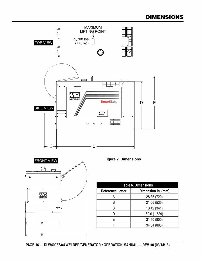
DIMENSIONS
Table 6. DimensionsReference Letter Dimension in. (mm)
A 28.35 (720)B 21.06 (535)C 13.42 (341)D 60.6 (1,539)E 31.50 (800)F 34.84 (885)
Figure 2. Dimensions
C
D E
A
B
Power Source Professionals.
MAXIMUMLIFTING POINT
1,708 lbs.(775 kg)TOP VIEW
FRONT VIEW
C
SIDE VIEW

DLW400ESA4 WELDER/GENERATOR • OPERATION MANUAL — REV. # 0 (03/14/18) — PAGE 17
NOTES

PAGE 18 — DLW400ESA4 WELDER/GENERATOR • OPERATION MANUAL — REV. #0 (03/14/18)
INSTALLATION
Figure 3. Welder-Generator Grounding Application
SmartStick
Power Source Professionals.
GROUND CABLE
WELDER-GENERATORGROUND LUG
REFERENCENEC 250
IF THE WELDER-GENERATOR IS PROVIDINGELECTRIC POWER TO A BUILDING VIA ATRANSFER SWITCH IT MUST BE CONNECTEDTO A GROUND ROD.
CONNECTING THE GROUND
Consult with local Electrical and Safety Codes for proper connection based on condition of use.
EXAMPLE of how to ground the unit if the condition of use requires such a device:
The ground terminal on the generator should always be used to connect the generator to a suitable ground when required.
The ground cable should be #8 size wire (aluminum) minimum. If copper wire is used, #10 size wire minimum should be used.
Connect one end of the ground cable terminal to the welder- generator ground point (Figure 3). Connect the other end of the ground cable to a suitable earth ground (ground rod).

DLW400ESA4 WELDER/GENERATOR • OPERATION MANUAL — REV. # 0 (03/14/18) — PAGE 19
INSTALLATION
OUTDOOR INSTALLATION
If possible install the welder-generator in a area that is free of debris, bystanders, and overhead obstructions. Make sure the welder-generator is on secure level ground so that it cannot slide or shift around.
The installation site must be relatively free from moisture and dust. All electrical equipment should be protected from excessive moisture. Failure to do so will result in deterioration of the insulation and will result in short circuits and grounding.
Foreign materials such as dust, sand, lint and abrasive materials have a tendency to cause excessive wear to engine and alternator parts.
INDOOR INSTALLATION
Exhaust gases from gas engines are extremely poisonous. Whenever an engine is installed indoors the exhaust fumes must be vented to the outside. The engine should be installed at least two feet from any outside wall. Using an exhaust pipe which is too long or too small can cause excessive back pressure which will cause the engine to heat excessively and possibly burn the valves.
PLACEMENT
This welder-generator should always be placed on a flat level surface when it is running. DO NOT place the welder-generator on slopes, the possibility exists that the unit could slide.
WARNING
Pay close attention to ventilation when operating the generator inside tunnels and caves. The engine exhaust contains noxious elements. Engine exhaust must be routed to a ventilated area
DANGER
Electric shock can occur when vibrators are used. Pay close attention to handling when operating vibrators and always use rubber boots and gloves to insulate the body from a short circuit.
WELDER-GENERATOR GROUNDING
If applicable ,to guard against electrical shock and possible damage to the generator, it is important to provide a good EARTH ground, (Figure 3).
Article 250 (Grounding) of the NEC handbook provides guidelines for proper grounding. It specifies that the cable ground shall be connected to the grounding system of the building as close to the point of cable entry as practical.
NEC article 250 specifices the following grounding requirements:
1. Use one of the following wire types to connect the generator to earth ground.
a. Copper 10 AWG (5.3 mm2) or larger.
b. Aluminum 8 AWG (8.4 mm2) or larger.
2. When grounding of the generator (Figure 3) is required, connect one end of the ground cable to the ground lug on the generator. Connect the other end of the ground cable to the ground rod (earth ground).
3. NEC article 250 specifies that the earth ground rod should be buried a minimum of 8 ft. into the ground.
NOTICE
The Occupational Safety and Health Administration (OSHA) and the National Electrical Code (NEC) recommend that if the welder-generator is providing electrical power to a structure (home, office shop, trailer or similar) it must be connected to a grounding electrode system, such as driven ground rod (Figure 3).
NOTICE
ALWAYS check with State, Province, District and Municipalities for electrical grounding requirements before using generator.
NOTICE
When connecting the generator to any buildings electrical system ALWAYS consult with a licensed electrician.

PAGE 20 — DLW400ESA4 WELDER/GENERATOR • OPERATION MANUAL — REV. #0 (03/14/18)
When used in single mode applications, Multiquip’s Model DLW400ESA4 Whisper Weld™ is a 400 amp DC welder. Dual mode applications provide 200 amps at each of the A and B welding terminals.
This unit incorporates a brushless revolving field simultaneous power generator, featuring stable arc characteristics, excellent vibration resistance and durability.
The unit also incorporates an AC power source (14 kW) which provides power for tools, submersible water pumps and other industrial and construction machinery.
In addition, this unit features incredibly quiet operation and can be operated at night or in restricted noise level locations.
This instruction manual provides information necessary for proper handling and operation of the welder/generator.
Please read the manual to ensure maximum operation and long service life.
CONTROL PANEL
The control panel is provided with the following components:
�DC Weld Meter
�Hour Meter
�Display Change Button
� Idle Stop Monitor
� Fuel Guage
�Warning Lamp/Hour Display Button
�Welding Regulation Control A/B
�Current Voltage Regulator Control A/B
�Single-Dual Selector Switch
�Welding Mode Selector Switch CC/CV
�E-Mode Selector Switch
�Operation Lamp
�Start Button
�Starter Switch
� 40 Amp Main Circuit Breaker
�AC Voltmeter
� Idle Stop Time Regulator Control
� Idle Stop Select Switch
�GFCI Sensing Module
GENERAL INFORMATION
OUTPUT TERMINAL PANEL
� 120 VAC GFCI Receptacle (5-20R)
� 120V Twist-Lock Output Receptacle (L5-30R)
� 240V Twist-Lock Output Receptacle (L6-30R)
� 120/240V Output Twist-Lock Receptacle (CS6369)
� 20 Amp 2P Circuit Breaker
� 30 Amp 1P Circuit Breaker
� 30 Amp 2P Circuit Breaker
�Ground Terminal
OPTIONS
The welder-generator has the following options:
� TRLRMP/TRLRMPXF Trailers
� Trailer Tool Box
�Cable Carrier
�Wired Remote Control
�Block Heater
� Fuel Heater
�Battery Tender
This welder-generator is powered by a 4 cylinder, 4-cycle liquid-cooled Kubota D902E4B diesel engine. This engine is designed to meet every performance requirement for the generator. Reference Table 4 for engine specifications.
In keeping with MQ Power’s policy of constantly improving its products, the specifications quoted herein are subject to change without prior notice.
EXTENSION CABLES
When electric power is to be provided to various tools or loads at some distance from the generator, extension cords are normally used. Cables should be sized to allow for distance in length and amperage so that the voltage drop between the generator and point of use (load) is held to a minimum. Use the cable selection chart (Table 9) as a guide for selecting proper extension cable size.

DLW400ESA4 WELDER/GENERATOR • OPERATION MANUAL — REV. # 0 (03/14/18) — PAGE 21
WELDING POLARITY AND DUTY CYCLE
WELDING POLARITY
Polarity indicates the direction of the current flow in that circuit. Since DC current moves in only one direction, polarity is important because the flow of current must be changed depending on the application.
By changing the polarity, the greatest amount of heat can be concentrated where it is most needed. With straight polarity (electrode negative), more heat is directed to the workplace. When using reverse polarity (electrode positive), more of the heat generated is directed to the electrode. Reference Figure 16.
NOTICE
When high quality welding is required DO NOT use AC power side of unit.
DUTY CYCLE
Duty cycle is based on a 10-minute welding period. Exceeding the duty cycle will have an affect on the welding process. The amperage will start dropping off and the welding process will not have the proper amperage required to proceed. If the duty cycle is exceeded, damage can occur to the welding machine.
The 10-minute duty cycle period means 100% welding. If the duty cycle is 60%, then you can only weld for six minutes and the machine must cool down for four minutes (Reference Table 7 below).
NOTICE
The American Welding Society sets all regulations and procedures for the welding industry. All welders are subject to the same regulations.
Table 7. 10-Minute Duty Cycle
Duty Cycle %
Welding ON Time (Min.)
Cool Down Time (Min.)
Welding Current (Amps)
Single Mode
1001 Continuous N/A 30 ~ 350
90 8 2 320
80 7 3 380
75 6 4 400
Dual Mode
1001 Continuous N/A 30 ~ 175
90 9 2 180
80 8 3 19075 7.5 4 200
1The DLW400ESA4 welder has a 100% duty cycle @ 350 amps (single mode) or 175 amps (dual mode).

PAGE 22 — DLW400ESA4 WELDER/GENERATOR • OPERATION MANUAL — REV. #0 (03/14/18)
DEFINITIONS OF WELDING TERMS
1. Weld – The unification of metallic parts by heating and allowing the metals to flow together or by hammering or compressing with or without previous heating.
2. Straight Polarity – A term for direct current electrode negative.
3. Reverse Polarity – A term for direct current electrode positive.
4. Manual Welding – A welding operation performed and controlled completely by hand.
5. AC or Alternating Current – AC is the kind of electricity, which reverses its direction periodically. For 60 cycle current, the current goes in one direction and then in the other direction 60 times in the same second, so that the current changes its direction 120 times in one second.
6. DC or Direct Current – DC is the kind of electricity, which only flows in one direction. The flow of electricity is from the power source to the application. In welding, an arc welding process wherein the power supply is at the arc is direct current.
7. ARC Force – An adjustment that allows the operator to fine tune the arc characteristics according to job requirements.
8. ARC Length – The distance from the end of the electrode to the point where the arc makes contact with the work surface.
9. ARC Voltage – The voltage across the welding arc.
10. ARC Blow – The deflection of an electric arc from its normal path because of magnetic forces.
11. Base Metal (Material) – The metal (material) to be welded, brazed, soldered, or cut.
12. E-Mode – Improves fuel efficiency by allowing the operator to weld with engine at idle speed at up to 240 amps (single mode). Reduces operating costs and noise levels.
13. Covered Electrode – A composite fill metal electrode consisting of a core of a bare electrode or metal-cored electrode to which a covering sufficient to provide a slag layer on the weld metal has been applied.
The covering may contain materials providing such functions as shielding from the atmosphere, deoxidization, and arc stabilization and can serve as a source of metallic additions to the weld.
14. Fillet Weld – A weld of triangular cross section joining two surfaces approximately at right angles to each other in a lap joint, T-joint or corner joint.
15. Tack Weld – A weld made to hold parts of a weldment for proper alignment until the final welds are made.
16. Shade Number – This number pertains to the lightness or darkness of the lens in the welding helmet. Lens number range from 2 to 14 where 2 would be the lightest lens and 14 would be the darkest lens.
17. CC or Constant Current – In this mode the amperage or current stays constant, but the direct current voltage will change depending on the arc length. This mode is applied to SMAW, FCAW and GTAW processes.
18. CV or Constant Voltage – In this mode the direct current voltage stays constant, but direct current amperage will change slightly. This mode is applied to GMAW, FCAW and GTAW.
19. Parallel Connection – Simply connect the positive terminals together, then connect the negative terminals together. Make sure that the machines are located as close together as possible.
Welding cables should be sized appropriately to handle the additional amperage. Rheostats must be set at the same amperage or as close as possible. (Note: Unlike competitive models, no parallel box is needed with Multiquip's welder-generators.)
WELDING PROCESSES
�SMAW – Shielded-Metal Arc Welding
� FCAW – Flux-Cored Arc Welding
�GMAW – Gas-Metal Arc Welding
�GTAW – Gas-Tungsten Arc Welding
�ACAC – Air Carbon Arc Cutting
WELDING TERMS

DLW400ESA4 WELDER/GENERATOR • OPERATION MANUAL — REV. # 0 (03/14/18) — PAGE 23
1. A/B DC Welding Output Terminals – Connect the DC welding cables to these terminals. Note the polarity marked on the welder-generator terminals. Select the appropriate polarities according to the application as specified in Table 15.
2. Control Panel – Contains controls and indicators necessary to operate the welder-generator.
3. Front Panel – Lift upwards to gain acess to the welder-generator control panel.
4. Rubber Stopper – Prevents scratching of front cover when front cover is folded back.
5. GFCI Ground Terminal — Used to connect external equipment ground so that the GFCI receptacle will have a ground path.
6. Door Lock – To prevent unauthorized use, place a padlock through the locking eye.
7. Frame Ground Lug — Connect a ground strap between this lug and a ground rod. Make sure that the ground rod is inserted deep into the ground to provide a good earth ground. Consult with local Electrical and Safety Codes for proper connection based on condition of use.
8. Fuel Drain Plug – Remove this plug to drain fuel from fuel tank Reference Table 4 for fuel tank capacity.
9. Coolant Drain Plug – Remove this plug to drain coolant from the radiator. Reference Table 4 for coolant capacity.
10. Oil Drain Plug – Remove this plug to drain engine oil. Reference Table 4 for engine oil capacity and oil type.
11. Door Release Latch – Pull outward to release cabinet door.
12. Air Inlet Vent — Allows outside air to enter the generator. NEVER block this opening.
13. Lifting Hook – Attach a strap or chain of adequate lifting capacity to this lifting point when the welder-generator must be lifted. Lifting device capacity must be able to lift 2000 lbs. ( 907 kg).
14. Fuel Cap – Remove this cap to add diesel fuel to the fuel tank. Reference Table 4 for engine fuel tank capacity and type fuel. Make sure cap is tightened securely. DO NOT over fill.
15. Radiator Inlet – Remove this cover to gain access to the radiator cap. Always allow engine to cool before removing radiator cap.
16. Engine Exhaust Outlet — Allows engine exhaust to exit the generator into the open air. NEVER block this opening.
Figure 4. Welder-GeneratorComponents
SmartStick
Power Source Professionals.
8 9 10
7
1
56
CONSTANTCURRENT DROOP
NORMAL
WELDINGREGULATOR
MIN.MAX.CURRENT/VOLTAGE
REGULATOR
2
4
3
11
TOP VIEW
SIDE VIEW
12
13
1415
16
12
COMPONENTS (WELDER/GENERATOR)

PAGE 24 — DLW400ESA4 WELDER/GENERATOR • OPERATION MANUAL — REV. #0 (03/14/18)
COMPONENTS (WELDER/GENERATOR)
1. Fuel Tank – Holds 11.1 gallons (42 liters). Fill with diesel fuel as specified in Table 4.
2. Radiator — Holds coolant/water necessary to keep the engine at a safe operating temperature. Remove this cap to add water/antifreeze when cool.
3. Expansion Bottle — Supplies coolant to the radiator when radiator coolant level is low. Fill to indicated level as shown on expansion bottle.
4. Engine Oil Filler Port — Remove this cap to add engine oil. Use only the recommended oil type. See Table 4 for engine oil capacity.
5. Oil Filter — Spin-on type, filters oil contaminants. Replace filter as recommended in the maintenance section of this manual.
Figure 5. Control Panel Components
1
2
3
67
4
5
6. Fuel Filter — Prevents dirt and other debris from entering the fuel system. Change fuel filter as recommended in the maintenance section of this manual.
7. Battery — Provides +12 VDC power for the welder-generator. When replacing battery (12V 45 AH) use only recommended type battery.

DLW400ESA4 WELDER/GENERATOR • OPERATION MANUAL — REV. # 0 (03/14/18) — PAGE 25
COMPONENTS (ENGINE)
INITIAL SERVICING
The engine (Figure 6) must be checked for proper lubrication and filled with fuel prior to operation. Refer to the manufacturer's engine manual for instructions and details of operation and servicing.
1. Fuel Feed Pump — Pumps fuel to the injection system.
2. Oil Dip Stick/Gauge — Remove to check amount and condition of oil in crankcase. Refill or replace with recommended type oil as listed in Table 4 and Table 10.
3. Speed Control Lever — Controls engine speed. This lever is factory set at 3600 rpm to maintain proper voltage and frequency. DO NOT adjust this lever out of factory range.
4. Injector Pump — Provides fuel under pressure to the injector nozzles.
5. Air Filter — Prevents dirt and other debris from entering the air intake system. Loosen clips on side of air filter canister to gain access to filter element. Replace with manufacturer's recommended type air cleaner only.
6. Cooling Fan Blades — Make sure cooling fan blades are not bent or broken. A damaged fan blade can cause the engine to run hot and overheat.
7. V-Belt — ALWAYS make sure V-belt is properly tensioned. A loose or defective V-belt can adversely affect the performance of the generator.
8. Starter — Starts engine when ignition key is rotated clockwise to the "ON" position.
9. Oil Pressure Switch — Monitors engine oil pressure. In the event of low oil pressure, engine will shutdown.
10. Alternator — Provides power to the +12VDC electrical system. Replace with only manufactures recommended type alternator.
Figure 6. Kubota 902E4B Diesel Engine

PAGE 26 — DLW400ESA4 WELDER/GENERATOR • OPERATION MANUAL — REV. #0 (03/14/18)
POWER RECEPTACLES
POWER RECEPTACLES
Located just to the right of the welding terminals are the auxilliary power receptacles. These power receptacles are described below.
120 VAC GFCI RECEPTACLE
The 120 VAC, 20 amp GFCI (Duplex Nema 5-20R) receptacle is protected by a 20 amp circuit breaker (CB4). The breaker is located above and to the right of GFCI receptacle. The green LED should be ON, indicating that the receptacle is working properly. If the red LED is flashing, DO NOT use the receptacle. Replace it immediately.
Pressing the reset button resets the GFCI receptacle after being tripped. Reference the maintance section of this manual for proper testing of the GFCI receptacle.
Figure 7. G.F.C.I. Receptacle
Twist Lock Receptacles
There are three auxiliary twist-lock receptacles. These power receptacles (Figure 8) are described below.
Figure 8. Auxiliary Twist-Lock Receptacles
� L5-30R — Provides 125 VAC @30 amps
� L6-30R — Provides 250 VAC @30 amps
�CS6369 — Provides 125/250 VAC @50 amps (Dual Voltage receptacle.
120 VACG.F.C.I.
RECEPTACLE
GREEN LED ONGFCI IS GOOD
RED LED FLASHINGREPLACE GFCIRESET
TEST
L5-30R L6-30R CS6369
125 VAC30 AMPS
250 VAC30 AMPS
125/250 VAC50 AMPS
SINGLE PHASE LOAD
Always be sure to check the nameplate on the generator and equipment to insure the wattage, amperage, frequency, and voltage requirements are satisfactorily supplied by the generator for operating the equipment.
Generally, the wattage listed on the nameplate of the equipment is its rated output. Equipment may require 130—150% more wattage than the rating on the nameplate, as the wattage is influenced by the efficiency, power factor and starting system of the equipment.
WATTS = VOLTAGE x AMPERAGE
The power factor of this welder-generator is 1.0. See Table 8 below when connecting loads.
NOTICE
If wattage is not given on the equipment’s name plate, approximate wattage may be determined by multiplying nameplate voltage by the nameplate amperage.
Table 8. Power Factor By LoadType of Load Power Factor
Single-phase induction motors 0.4-0.75
Electric heaters, incandescent lamps 1.0Fluorescent lamps, mercury lamps 0.4-0.9Electronic devices, communication equipment 1.0
Common power tools 0.8
Table 9. Cable Selection (60 Hz, Single Phase Operation)
Current in
Amperes
Load in Watts Maximum Allowable Cable Length
At 100 Volts
At 200 Volts #10 Wire #12 Wire #14 Wire #16 Wire
2.5 300 600 1000 ft. 600 ft. 375 ft. 250 ft.
5 600 1200 500 ft. 300 ft. 200 ft. 125 ft.
7.5 900 1800 350 ft. 200 ft. 125 ft. 100 ft.
10 1200 2400 250 ft. 150 ft. 100 ft.
15 1800 3600 150 ft. 100 ft. 65 ft.
20 2400 4800 125 ft. 75 ft. 50 ft.
CAUTION: Equipment damage can result from low voltage

DLW400ESA4 WELDER/GENERATOR • OPERATION MANUAL — REV. # 0 (03/14/18) — PAGE 27
CONTROL PANEL
1. DC Weld Meter – A digital display that indicates the amperage and voltage at the A and B welding terminals. In addition, this display is also used to display engine error codes and other welder-generator diagnostic information. Reference Table 27 for engine error code definitions.
2. Hour Meter – A digital display that indicates the welding hours on terminals A and B. The ODO indicates total machine hours of use.
3. ODO-A-B Display Change Button – When pressed allows hour meter display to cycle between ODO (run time) and welding output terminals A and B.
4. Hour Display Button – Only used when engine is off. When pressed and held, ODO, loaded and unloaded hours of operation will be displayed on hour meter display.
Press display change button while holding down hour display button to toggle between ODO and A and B welding output terminals.
5. Idle Stop Monitor – Consists of four status LEDs, if any of the LEDs are lit or blinking, idle stop function will not work.
6. Fuel Tank LED Indicators – Consists of seven status LEDs indicating the amount of fuel in the fuel tank.
7. Engine Warning Lamp Indicators – Consists of three status LEDs, oil pressure, high coolant temperature and battery charge. If any of the LEDs are lit, the engine will shutdown automatically.
Press display change button while holding down hour display button to toggle between ODO and A and B welding output terminals.
8. Terminals A/B ARC Force Regulator Control – An adjustment that allows the operator to fine tune the arc characteristics according to job requirements. This control allows the user to adjust the arc from a soft smooth arc to a more aggressive digging arc.
Placing the voltage selector switch in the single mode position will access terminal A. Placing the voltage selector switch in the dual mode will access both terminals A and B.
9. Terminals A/B Current/Voltage Reg. Control – Place this knob in the desired setting when welding is required. Current range is from 30 to 400 amps (CC single mode), 30 to 200 amps (CC dual mode).
Placing the voltage selector switch in the single mode position will access terminal A. Placing the voltage selector switch in the dual mode will access both terminals A and B.
10. Single/Dual Selector Switch – Place this switch in the desired welding mode. DO NOT switch under load.
MIN. MAX.
DROOP
NORMAL
CONSTANTCURRENT
WELDINGREGULATION
CURRENT/VOLTAGEREGULATOR
TERMINALA
MIN. MAX.
DROOP
NORMAL
CONSTANTCURRENT
WELDINGREGULATION
CURRENT/VOLTAGEREGULATOR
SINGLE DUALCC MODE
30~340A
CC MODE
30~200A
CV MODE
14~36V
(~400A)
CV MODE
14~36V
(~200A)
DC ADJUSTMENT
FOR TERMINALS
“A” AND “B”
DC ADJUSTMENT
FOR TERMINALS
“A” OR “B”
SINGLE-DUAL SELECTOR SWITCH
CAUTION: DO NOT SWITCH UNDER LOAD
TERMINALB
DC WELD METER
IDLE STOP MONITOR
Idle stop will not work when lamp is litUnit will not restart when lamp is blinking.
RestartCharge
AC Load Main CBON
Side DoorOpen
TERMINAL: A TERMINAL: B
AV
Welding Welding
AV
Fuel Level
WARNING LAMP
E 1/2 F
Hour Display
CV
CC
WELDINGMODE
VARIABLE/LOW
HIGH
e MODE SELECTORSWITCH
HIGH/LOW
OPERATIONLAMP
ENGINE STARTBUTTON
STOP RUN
STARTERSWITCH
V
100
50 100
200
300
1500
0
AUTO RESET
POWER
FAULT
15 MIN.
1 MIN. 30 MIN.OFF
40 AAC220V 25kA
PSE
JET
Fe
Before using idle stopfuction turn main CB off.
ON
OFF
TIME REGULATOR SELECTOR SWITCH
G.F.C.I.SENSING MODULE
AC CIRCUIT BREAKER(G.F.C.I. PROTECTED)
MAIN & No.1
NO.150A
120V/240V
DC 400 AMP/AC14kWMODEL DLW-400ESA4
DC WELDER/AC GENERATOR
IDLE STOP
5
10
8
1 2
6
7
9
HOUR METERODO
A
Bh
0D0-A-BDisplay Change
3 4
Figure 9. Control Panel

PAGE 28 — DLW400ESA4 WELDER/GENERATOR • OPERATION MANUAL — REV. #0 (03/14/18)
CONTROL PANEL (CONTINUED)
1. Welding Mode – Place this rocker switch in the desired welding mode, up for constant voltage (CV), down for constant current (CC).
2. E-Mode Selector Switch – This 3-position rocker switch allows the engine to operate at low speed with no load or low welding load. The three switch positions are defined as follows:
� Variable/Low – When the welding power and AC power are not in use, engine will run at lowest speed (2300 rpm). During welding operations engine speed is automatically controlled depending on welding output. However if an AC load of 100 watts or more is detected, the engine will be operated at high speed.
� High/Low – With an AC load of 100 watts or more or while welding, the engine will be operated at high speed (3600 rpm) to respond to the preset AC frequency regardless of the welding work.
� High Position – Engine is always operated at high speed (3600 rpm) with or without load.
3. Main Breaker – Place this 40 amp breaker (CB1) in the ON position (up) to provide AC voltage to auxillary circuit breakers CB2, CB3 and CB4. This breaker is not requred when welding.
4. Time Regulator Control – Indicates the amount of
time (1~30 min.) the unit will run before automatic shutdown will occur. This control is only active in the idle stop mode.
5. AC-Voltmeter – This voltmeter indicates the rated 60 Hz (single-phase) output voltage. In addition, the voltmeter can also be used as a diagnostic tool.
If the voltmeter indicator (needle) is below the rated voltage, engine problems may exist (low/high RPM's). To prevent damage to the generator or power tools, turn the generator OFF and consult your authorized Multiquip service dealer.
6. Selector Switch – Place this switch in the ON position to enable the idle stop function.
7. GFCI Sensing Module – Interrupts power when a ground fault exists.
8. Operation Lamp – When lit, indicates unit is ON and in use.
9. Engine Start Button – After the ignition key has been placed in the RUN position, press this button once to start the engine. Continuous pushing of the button is not required to start the engine.
10. Starter Switch — Place ignition key in RUN position, then press engine start button to start engine.
Figure 10. Control Panel (Continued)
MIN. MAX.
DROOP
NORMAL
CONSTANTCURRENT
WELDINGREGULATION
CURRENT/VOLTAGEREGULATOR
TERMINALA
MIN. MAX.
DROOP
NORMAL
CONSTANTCURRENT WELDING
REGULATION
CURRENT/VOLTAGEREGULATOR
SINGLE DUALCC MODE
30~340A
CC MODE
30~200A
CV MODE
14~36V
(~400A)
CV MODE
14~36V
(~200A)
DC ADJUSTMENT
FOR TERMINALS
“A” AND “B”
DC ADJUSTMENT
FOR TERMINALS
“A” OR “B”
SINGLE-DUAL SELECTOR SWITCH
CAUTION: DO NOT SWITCH UNDER LOAD
TERMINALB
DC WELD METER
IDLE STOP MONITOR
Idle stop will not work when lamp is litUnit will not restart when lamp is blinking.
RestartCharge
AC Load Main CBON
Side DoorOpen
TERMINAL: A TERMINAL: B
AV
Welding Welding
AV
HOUR METERODO
A
Bh
0D0-A-BDisplay Change
Fuel Level
WARNING LAMP
E 1/2 F
Hour Display
CV
CC
WELDINGMODE
VARIABLE/LOW
HIGH
e MODE SELECTORSWITCH
HIGH/LOW
OPERATIONLAMP
ENGINE STARTBUTTON
STOP RUN
STARTERSWITCH
V
100
50 100
200
300
1500
0
AUTO RESET
POWER
FAULT
15 MIN.
1 MIN. 30 MIN.OFF
40 AAC220V 25kA
PSE
JET
Fe
Before usi ng idle stopfuction turn main CB off.
ON
OFF
TIME REGULATOR SELECTOR SWITCH
G.F.C.I.SENSING MODULE
AC CIRCUIT BREAKER(G.F.C.I. PROTECTED)
MAIN & No.1
NO.150A
120V/240V
IDLE STOP
1 2 3 4 5
6
7
8
9
10
DC 400 AMP/AC14kWMODEL DLW-400ESA4
DC WELDER/AC GENERATOR

DLW400ESA4 WELDER/GENERATOR • OPERATION MANUAL — REV. # 0 (03/14/18) — PAGE 29
INSPECTION
LUBRICATION OILFill the engine crankcase with lubricating oil through the filler hole, but DO NOT overfill. Make sure the generator is level and verify that the oil level is maintained between the two notches (Figure 11) on the dipstick. See Table 10 for proper selection of engine oil.
Figure 11. Engine Oil Dipstick
When checking the engine oil, be sure to check if the oil is clean. If the oil is not clean, drain the oil by removing the oil drain plug, and refill with the specified amount of oil as outlined in the Kubota Engine Owner’s Manual. Oil should be warm before draining.When low sulfur or ultra low diesel fuel is used, it is recommended that CF-4 or CG-4 (classification) engine oil be used. Reference Table 10 when replacing engine oil.
FUEL CHECK
Table 10. Recommended Motor Oil
DANGER
Fuel spillage on a hot engine can cause a fire or explosion. If fuel spillage occurs, wipe up the spilled fuel completely to prevent fire hazards. NEVER smoke around or near the generator.
REFILLING THE FUEL SYSTEM
1. Lift the control panel lid and fold backwards.
2. Next, insert the ignition key into the starter switch and place in the RUN position.
3. Read the fuel guage status LEDs (Figure 12) on the control panel and determine if the fuel level is low. Reference Table 11 for LED fuel gauge level indication.
4. Place ignition key in STOP position and remove ignition key from starter switch.
Figure 12. Fuel Gauge
If fuel level is low, ALWAYS fill the fuel tank with clean fresh low sulfur or ultra low sulfur diesel fuel. No. 2 diesel fuel can be used as an alternative. DO NOT fill the fuel tank beyond its capacity.
Pay attention to the fuel tank capacity when replenishing fuel. The fuel tank cap must be closed tightly after filling. Handle fuel in a safety container. If the container does not have a spout, use a funnel. Wipe up any spilled fuel immediately.
CAUTION
ONLY properly trained personnel who have read and understand this section should refill the fuel tank system.
Table 11. Fuel Gauge LEDs
LED # LED Color Fuel Tank Level gal. (liters)
1Red (Empty) 0~ 2.4 (0 ~ 9)
Green 2.4~ 3.4 (9 ~ 12.8)
2 Green 3.4~4.8 (9.0 ~ 18.1)
3 Green 4.8~5.8 (18.1 ~ 22)
4 Green 5.8~6.9 (22 ~ 26.1)
5 Green 6.9~7.9 (26.1 ~ 29.9)
6 Green 7.9~9.2 (29.9 ~ 34.8)
7 Green (Full) 9.2~11.1 (34.8 ~ 42.0)

PAGE 30 — DLW400ESA4 WELDER/GENERATOR • OPERATION MANUAL — REV. #0 (03/14/18)
COOLANT (ANTIFREEZE/SUMMER COOLANT/WATER)
Kubota recommends antifreeze/summer coolant for use in their engines, which can be purchased in concentrate (and mixed with 50% demineralized water) or pre-diluted. See the Kubota Engine Owner’s Manual for further details.
Day-to-day addition of coolant is done from the recovery tank. When adding coolant to the radiator, DO NOT remove the radiator cap until the unit has completely cooled. See Table 12 for engine, radiator, and recovery tank coolant capacities. Make sure the coolant level in the recovery tank is always between the “H” and the “L” markings.
Operation in Freezing Weather
When operating in freezing weather, be certain the proper amount of antifreeze (Table 13) has been added.
WARNING
If adding coolant/antifreeze mix to the radiator, DO NOT remove the radiator cap until the unit has completely cooled. The possibility of hot! coolant exists which can cause severe burns.
Table 12. Coolant CapacityEngine and Radiator .69 gal (2.6 liters)
Reserve Tank .22 gal (.832 liters)
Table 13. Anti-Freeze Operating Temperatures
Vol % Anti-Freeze
Freezing Point
°C °F
50 -37 -34
NOTICE
When the antifreeze is mixed with water, the antifreeze mixing ratio must be less than 50%.
INSPECTION
CLEANING THE RADIATOR
The engine may overheat if the radiator fins become overloaded with dust or debris. Periodically clean the radiator fins with compressed air. Cleaning inside the machine is dangerous, so clean only with the engine turned off and the negative battery terminal disconnected.
AIR CLEANER
Periodic cleaning/replacement is necessary. Inspect air cleaner as referenced in the maintenance section of this manual.
FAN BELT TENSION
A slack fan belt may contribute to overheating or to insufficient charging of the battery. Inspect the fan belt for damage, wear and adjust it in accordance with the Kubota Engine Owner’s Manual.
The fan belt tension (Figure 13) is proper if the fan belt bends 0.4~0.6 inches (10~15 mm) when depressed with the thumb as shown below.
Figure 13. Fan Belt Tension
0.4~0.6 IN.(10~15MM)
DEFLECTION
CAUTION
NEVER place hands near the belts or fan while the welder-generator set is running.

DLW400ESA4 WELDER/GENERATOR • OPERATION MANUAL — REV. # 0 (03/14/18) — PAGE 31
BATTERY
This unit is of negative ground DO NOT connect in reverse. Always maintain battery fluid level between the specified marks. Battery life will be shortened, if the fluid levels are not properly maintained. Add only distilled water when replenishment is necessary.
DO NOT over fill. Check to see whether the battery cables are loose. Poor contact may result in poor starting or malfunctions. Always keep the terminals firmly tightened. Coat the terminals with an approved battery terminal treatment compound. Replace battery with only recommended type battery. The battery type used in this generator is BCI Group 22F (CCA:410).
The battery is sufficiently charged if the specific gravity of the battery fluid is 1.28 (at 68° F). If the specific gravity should fall to 1.245 or lower, it indicates that the battery is dead and needs to be recharged or replaced.
Before charging the battery with an external electric source, be sure to disconnect the battery cables.
BATTERY CABLE INSTALLATION
ALWAYS be sure the battery cables (Figure 14) are properly connected to the battery terminals as shown below. RED cable is connected to the positive terminal of the battery, and the BLACK cable is connected to the negative terminal of the battery.
Figure 14. Battery
CAUTION
ALWAYS disconnect the negative terminal FIRST and reconnect negative terminal LAST.
POSITIVE
NEGATIVE
INSPECTION/SETUP
SELECTING THE WELDING CABLE
The welding cable should be larger in size as it becomes longer or its current becomes higher. Prepare a cable with suitable size by referring to Table 14.
WELDING CABLE AND POLARITIES
1. ALWAYS attach terminal ring connectors (Figure 15) to the end of the welding cable that will be connected to the welder output terminals.
2. NEVER connect exposed wires (Figure 15) directly to the welder output terminals. Exposed wiring may cause shocks or di-electric breakdown from poor contact.
Figure 15. Welder Output Terminals
3. Connect the welding cables to the welder output terminals located just below the control panel. The output terminals are marked (+) and (–) polarities. Select the appropriate polarities according to the application. Reference Table 15.
Table 14. Selecting the Welding Cable
Length (ft)
Current (A)50 100 125 150 200 250 300
100 #4 #4 #4 #4 #3 #2 #1
150 #3 #3 #3 #2 #1 #1/0 #2/0
200 #2 #2 #2 #1 #1/0 #2/0 #3/0
250 #1 #1 #1 #1/0 #2/0 #3/0 #4/0
300 #1/0 #1/0 #1/0 #2/0 #3/0 #4/0 #2-2/0
400 #2/0 #2/0 #2/0 #3/0 #4/0 #2-2/0 #2-3/0
Cable size values are based on a voltage drop of maximum 4 volts.
DANGER
NEVER allow the welding cable terminal to come in contact with the adjacent welding terminal or the welder-generator frame when the machine is in use. The possibility exists of electrical shock or short circuit which could cause a fire resulting in severe bodily harm and damage to the equipment.

PAGE 32 — DLW400ESA4 WELDER/GENERATOR • OPERATION MANUAL — REV. #0 (03/14/18)
SETUP
Figure 16. Welding Cable Connections (Electrode Type Correct)
Table 15. Polarities and ApplicationsPolarity Welding Method Typical Applications
Straight Polarity
(+)...Grounding (base metal)(–)...Welding holder
Arc welding for steel material of general structures, and for thick platesArc welding for copper alloy
Reverse Polarity
(+)...Welding holder
(–)...Grounding (base metal)
Build-up welding Air gouging Arc welding of thin plates Arc welding of stainless steel
Figure 17. Welding Cable Connections (Electrode Type Incorrect)
4. For CC mode welding, select the appropriate electrode size in accordance with Table 16 (Single Mode Operation) or Table 17 (Dual Mode Operation).
5. Attach the clamp holder to the electrode as shown in Figure 16 and Figure 17.
WARNING
When operating the welder in dual mode, NEVER connect the positive and negative terminals (Figure 17) from the A and B sides together.
This condition may cause the voltage between the welding terminals to double under no load, causing damage to the equipment and electrical shock to personnel.
TERM
INA
L: A
WELD
ING
OU
TPUT T
ERM
INA
L
ELECTRODE
WORK
STRAIGHT
POLARITY
WELDER OUTPUTTERMINALS
B
TERM
INA
L: B
WELD
ING
OU
TPUT T
ERM
INA
L
A
CLAMPHOLDER
JUMPER
REVERSE
POLARITY
TERM
INA
L: A
WELD
ING
OU
TPUT T
ERM
INA
L
ELECTRODE
WORK A
STRAIGHT
POLARITY
WELDER OUTPUTTERMINALS
B
TERM
INA
L: B
WELD
ING
OU
TPUT T
ERM
INA
L
A
CLAMPHOLDER
REVERSE
POLARITY
WORK B
CORRECT
INCORRECT

DLW400ESA4 WELDER/GENERATOR • OPERATION MANUAL — REV. # 0 (03/14/18) — PAGE 33
CV Mode Welding
1. Connect the welding cables from the welder-generator to the wire feeder as shown in Figure 18.
Figure 18. CV Setup (Wire Feeder)
Table 16. Current Range/Electrode Size (Single Mode Operation)
Low 2300 rpm
Variable 2300~3600 rpm
High 3600 rpm
Current/ Range Amps 30~200A 30~400A 30~400A
Electrode Size Diameter 3/32" ~ 3/16" 3/32" ~ 5/16" 3/32" ~ 5/16"
Table 17. Current Range/Electrode Size (Dual Mode Operation)
Low 2300 rpm
Variable 2300~3600 rpm
High 3600 rpm
Current/ Range Amps 30~200A 30~200A 30~200A
Electrode Size Diameter 3/32" ~ 3/16" 3/32" ~ 3/16" 3/32" ~ 3/16"
NOTICE
A wire feeder (Figure 18) can be used when in the CV mode. The wire feeder utilitizes the power output from the DC welding terminals. Consult the manufacturer's instructions when connecting the wire feeder to the welder-generator.
SETUP
2. Select the appropriate welding wire size depending on the application as referenced in the wire feeder instruction manual.
3. After the correct wire size has been determined, install wire spool onto wire feeder.
4. Adjust the CV voltage regulator for the desired DC voltage to the wire feeder.
5. Reference Table 18 when using flux-cored wires commonly known as Flux Cored Arc Welding (FCAW) process. This process has two types of flux-cored wires. One is self-shielded (FCAW-S), the other is gas-shielded (FCAW-G).
Table 18. Flux-Cored Wires (Self/Gas Shielded)
Weld Process/ WireType Welder Output Terminal
Gas-Shielded Connect to positive (+) terminal
Self-Shielded Connect polarity as defined by the wire manufacturer instructions
NR-211MP Wire Connect to negative (–) terminal
NR-311MP Wire Connect to negative (–) terminal
NR-232MP Wire Connect to negative (–) terminal

PAGE 34 — DLW400ESA4 WELDER/GENERATOR • OPERATION MANUAL — REV. #0 (03/14/18)
OPERATION
Before starting the welder-generator, the pre-inspection safety checks must be completed. In addition, do a general survey of the area surrounding the machine making sure the area is safe, air vents of the machine are not blocked and the exhaust can be freely discharged.
The machine can be started, once the people surrounding the machine have been notified that the machine is going to be used.
STARTING THE ENGINE
1. To protect the welder-generator from an overload, a 3-pole, 40 amp, main circuit breaker (Figure 19) is provided. In addition, there are three circuit breakers provided to protect the GFCI and auxiliary receptacles from overload. Make sure to switch all circuit breakers to the OFF position prior to starting the welder-generators.
Figure 19. Circuit Breakers
2. Place the fuel valve lever (Figure 20) in the ON position.
Figure 20. Fuel Valve Lever (ON)
240V20A
120V
OFF
No.4
30A
No.3
AC CIRCUIT PROTECTOR
30A
No.2
OFF OFF
L5-30R L6-30R CS6369
240V30A
No.2
240V30A
No.2
120V/240V40A
No.1
5-20R
OFF
40 AAC220V 25kA
PSE
JET
Fe
CB4 CB3 CB2
CB1
OFF
ON
FUEL VALVELEVER
3. Close all enclosure doors (Figure 21).
Figure 21. Enclosure Doors (Closed)
4. Place the idle stop selector switch (Figure 22) in the OFF position.
Figure 22. Idle Stop Selector Switch (OFF)
5. Insert the ignition key (Figure 23) into the “Starter Switch” and turn the key clockwise to the RUN position.
Figure 23. Ignition Key (RUN Position)
NOTICE
DO NOT operate this equipment with the enclosure doors open. Operating the unit with the doors open during operation will effect the internal cooling air-flow of the machine and will allow foreign substances (e.g. dust and dirt) to be drawn into the unit.

DLW400ESA4 WELDER/GENERATOR • OPERATION MANUAL — REV. # 0 (03/14/18) — PAGE 35
6. Verify operation lamp is lit (ON). Reference Figure 24.
Figure 24. Operation Lamp
7. Next, verify that the ODO LED indicator is lit (ON) and the hour meter display (Figure 25) shows total machine hour used.
Figure 25. Hour Meter (Run Position)
8. Next, press the GREEN engine start button (Figure 26) only once. Continuous pressing of the button is not necessary. The engine will automatically start once the count down sequence has been completed.
Figure 26. Engine Start Button
OPERATION
9. Verify that right-most decimal (Figure 27) on the hour meter display is flashing.
Figure 27. Hour Meter (Engine Start)
10. The DC welding meter will display the pre-heating countdown time value. The example shown in Figure 28 indicates 10 seconds before engine cranking can begin.
Figure 28. DC Weld Meter (Countdown)
11. When the pre-heating time has been completed, engine cranking will begin and the engine will be started.
12. After the engine starts, let the machine idle for 5~10 minutes to warm-up.
13. Carefully check the engine for abnormal vibration (noise), oil leakage, fuel leakage, cooling water leakage and air leakage. Also, verify if any alarm lights are lit. If any abnormal conditions exits, turn the engine OFF and correct the problem.
NOTICE
All pre-heating and cranking are automatic. The pre-heating time and cranking times are automatically controlled by the temperature sensor located on the unit. The lower the temperature, the longer the pre-heating and cranking time.
Three sets of pre-heating and cranking times are repeated until the engine is started. If the engine is not started with 3 sets of repetition, the DC Weld Meter will indicate E06 (starting failure), E01 (low oil pressure) and E03 (insufficient system charging).

PAGE 36 — DLW400ESA4 WELDER/GENERATOR • OPERATION MANUAL — REV. #0 (03/14/18)
SINGLE MODE WELDING (CC)
1. Place the welding mode selector switch (Figure 29) in the single mode position.
Figure 29. Single-Dual Selector Switch (Single Position)
2. For CC welding, place the welding mode rocker switch in the CC position (down).
Figure 30. Welding Mode Switch (CC Mode)
3. Place e-Mode selector switch (Figure 31) in the desired position as defined by Table 19. This switch is a 3-position rocker switch.
Figure 31. E-Mode Selector Switch (CC Mode)
OPERATION
4. If welding is started with the e-mode selector switch in the variable/low position, the standard welding load voltage is automatically calculated based on the preset welding current (Figure 32) and the engine speed will be controlled by the available kW capacity of the unit for either single or dual mode operation.
The engine will then be placed into low-speed operation about 9~10 seconds after a pause of welding work.
Figure 32. E-Mode Engine Variable Control
Table 19. Current Range/Engine Speed (Single Mode Operation)
e Mode Selector Switch
Low 2300 rpm
Variable 2300~3600 rpm
High 3600 rpm
Variable/ Low
30~200A See Notes
200~400A See Notes —
High/Low See Notes — 30~400A
High — — 30~400A See Notes
Note 1: If using two welders connected with different polartities to weld the same work, the voltage between the holders may cause electric shock to the operator.
Note 2: If using two welders connected with different polartities to weld the same work, use separate grounds for each welder.
Note 3: NEVER switch the Single-Dual Selector Switch during welding operations. Switch contacting failure may occur.
NOTICE
If the welding work requires a current of 240 amps or less for single mode applications, place the e-mode selector switch in the high/low or high position if bead appearance or welding faults are a concern.
In addition, place the e-mode selector switch in the high position if an AC load of 100 watts or an AC load with a magnet switch is used.
3.2mm Dual (140Ax2)
Ø
4mm Dual (160Ax2)
Ø
4mm Single (~200A)
Preset Welding (kW)
Eng
ine
Rev
olut
ion
(rpm
)
0 20002000
2200
2400
2600
2800
3000
3200
3400
3600
3800
4000 6000 8000 10000 12000
Ø

DLW400ESA4 WELDER/GENERATOR • OPERATION MANUAL — REV. # 0 (03/14/18) — PAGE 37
5. Next, set the current/voltage regulator control knob (Figure 33) in accordance with the selected electrode size as referenced in Table 16.
Figure 33. Current/Voltage Regulator Control Knob (Current Adjust)
6. The selected current (amps) will be displayed on the DC weld meter. The example shown in Figure 34 is for a constant current value of 135 amps.
Figure 34. DC Weld Meter (135 Amps)
7. Set the welding regulation control knob (Figure 35) to the desired setting.
Figure 35. Welding Regulation Control Knob
NOTICE
The welding regulation control knob is an adjustment used to control the length and strength of the welding arc. In addition this control can be used to fine tune the arc based on the specific application being used.
OPERATION
DUAL MODE WELDING (CC)
1. Place the welding mode selector switch (Figure 36) in the dual mode position.
Figure 36. Single-Dual Selector Switch (Dual Position)
2. Follow steps 2 through 6 as outlined in the Single Mode Welding (CC) section and reference Table 20 instead of Table 19.
NOTICE
NEVER switch the single dual selector switch when welding. The possibility exists of contact failure which could cause arcing thus causing a fire and damage to the equipment.
Table 20. Current Range/Engine Speed (Dual Mode Operation)
e Mode Selector Switch
Low 2300 rpm
Variable 2300~3600 rpm
High 3600 rpm
Variable/ Low
A+B Total 30~200A See Note
A+B Total 200~400A No Load
—
High/Low See Note — A+B Total 30~400A
High — —A+B Total 30~400A See Note
Note: Reference notes 1, 2 and 3 as specified in Table 19.

PAGE 38 — DLW400ESA4 WELDER/GENERATOR • OPERATION MANUAL — REV. #0 (03/14/18)
CV Welding
1. For CV welding, place the welding mode rocker switch in the CV position (up).
Figure 37. Welding Mode Switch (CV Mode)
2. Place the welding mode selector switch (Figure 38) in either the single or dual mode position.
Figure 38. Single-Dual Selector Switch
3. Place e-Mode selector switch (Figure 39) in the desired position as defined by Table 21 or Table 22. This switch is a 3-position rocker switch.
Figure 39. E-Mode Selector Switch (CV Mode)
NOTICE
If the single-dual selector switch has been placed in the single position, B-side welding terminals cannot be used.
OPERATION
4. Using the welding voltage control knob (Figure 40) adjust the voltage to the desired setting as referenced in Table 21 (Single Mode) or Table 22 (Dual Mode).
Figure 40. Current/Voltage Regulator Control Knob (Voltage Adjust)
5. The selected voltage will be displayed on the DC weld meter (Figure 41).
Table 21. Voltage Range/Engine Speed (Single Mode Operation)
e Mode Selector Switch
Low 2300 rpm
Variable 2300~3600 rpm
High 3600 rpm
Variable/ Low
14~17 VDC See Notes 18~35 VDC —
High/Low See Notes — 14~35 VDC
High — — 14~35 VDC See Notes
Note 1: If using two welders connected with different polartities to weld the same work, the voltage between the holders may cause electric shock to the operator.
Note 2: If using two welders connected with different polartities to weld the same work, use separate grounds for each welder.
Note 3: NEVER switch the Single-Dual Selector Switch during welding operations. Switch contacting failure may occur.
Table 22. Voltage Range/Engine Speed (Dual Mode Operation)
e Mode Selector Switch
Low 2300 rpm
Variable 2300~3600 rpm
High 3600 rpm
Variable/ Low
A+B Total 14~25V
See Note
A+B Total 14~56V
See Note—
High/Low See Note — A+B Total 14~56V
High — —A+B Total 14~56V
See Note
Note: Reference notes 1, 2 and 3 as specified in Table 21.

DLW400ESA4 WELDER/GENERATOR • OPERATION MANUAL — REV. # 0 (03/14/18) — PAGE 39
OPERATION
Figure 41. DC Weld Meter (18 VDC)
6. Adjust welding current with the current regulator control on the wire feeder.
Idle Stop Function
1. Place all circut breakers in the OFF position.
2. The idle stop function will not work if the following lamps are ON or BLINKING as referenced in Figure 42 and below:
�Restart Charge Lamp – If this lamp is ON or blinking the engine cannot be started.
�AC Load Lamp – If lamp is blinking, indicates that the ON/OFF power switch of a power tool connected to the GFCI receptacle has been left in the ON position.
NOTICE
The idle stop function when selected allows the welder-generator to be started or stopped remotely. Warning signs should be posted around the equipment indicating that the equiment can start without warning. All children and unauthorized personnel should be kept away when the equipment is operating in this mode.
NOTICE
Whenever the unit is started either via pushbutton control or the Smart Stick™ function, battery voltage will be consumed. The restart charge lamp will turn on during engine cranking.
The lamp will remain on until the battery has received sufficient charge. Once a sufficient charge has been achieved, the lamp will turn off. This concept is in place to prevent the operator from shutting down and restarting the unit multiple times in a shorten time frame.
Multiple starts in a shorten time frame will deplete the battery charge, and cause battery replacement.
�Main Circuit Breaker On Lamp – If this lamp is blinking or ON, indicates that the main circuit breaker is in the ON position.
�Side Door Open – If lamp is blinking, indicates side door is open.
Figure 42. Idle Stop Monitor
3. If any of the status lamps as referenced in Figure 42 are ON, correct the problem before using the idle stop function.
4. Place the idle stop selector switch (Figure 43) in the ON position.
Figure 43. Idle Stop Selector Switch (ON)
5. Next, set the time regulator to the desired setting. The example shown in (Figure 44) indicates 15 minutes.
Figure 44. Time Regulator
IDLE STOP MONITOR
Idle stop will not work when lamp is litUnit will not restart when lamp is blinking.
RestartCharge
AC Load Main CBON
Side DoorOpen
WARNING
When using the idle stop function, be careful not to come in contact (bare hands) with the welding holder, welding terminals and the load connected to the GFCI receptacle. The possibility of electrical shock exist.

PAGE 40 — DLW400ESA4 WELDER/GENERATOR • OPERATION MANUAL — REV. #0 (03/14/18)
6. The welding process will be stopped once the preset time (1-30 minutes) has been reached. The engine will shutdown and the "1d5" message will be displayed on the DC Weld Meter (Figure 45).
Figure 45. DC Weld Meter (Idle Stop)
RESTARTING FROM IDLE STOP (WELDING SIDE)
This section will describe how the welder detects the restart signal when idle stop selector switch has been placed in the ON position (welder side).
1. The stopping of the engine creates a restart signal, a voltage of about 15 VDC at the welding terminals.
2. To decrease the voltage at the welding terminals, tap the welding electrode tip to the welding material.
3. If the detecting circuit detects the varying signal twice or more (tap, tap, tap), the engine will be restarted automatically.
Figure 46. Restart Signal (Welder Side)
DC WELD METER
TERMINAL: A TERMINAL: B
AV
Welding Welding
AV
TERM
INA
L: A
WELD
ING
OU
TPUT T
ERM
INA
L
ELECTRODE
WORK
B
TERM
INA
L: B
WELD
ING
OU
TPUT T
ERM
INA
L
A
CLAMPHOLDER
TAP #1
WORK
CLAMPHOLDER
WORK WORK
TAP #2
ENGINE
RESTART
15 VDC
OPERATION
RESTARTING FROM IDLE STOP (GENERATOR SIDE)
This section will describe how the welder detects the restart signal when idle stop selector switch has been placed in the ON position (generator side).
1. To detect the restart signal, a voltage of about 15 VDC will be generated at the GFCI receptacle during the stopping of the engine.
2. Insert the plug from a power tool such as a electric drill or saw into the GFCI receptacle on the welder/generator.
3. Make sure the ON/OFF switch on the power tool is in the OFF position.
4. Next, toggle the ON/OFF switch twice with the switch ending up in the OFF position.
Figure 47. Restart Signal (Generator Side)
5. If the detecting circuit detects the varying signal twice or more (on, off, on and off) the engine will be restarted automatically.
GFCIRECEPTACLE
ELECTRICDRILL ON OFF ON OFF
POWER SWITCH
NOTICE
Make sure that the welding electrode tip (Figure 46) is free of any residue from the welding work and also make sure that the welding surface is not corroded. Both of these conditions could affect the restart signal.
Excessive residue on the electrode tip and corrosion on the welding surface may cause the engine not to start even after repeated tapping of the electrode on the work surface.

DLW400ESA4 WELDER/GENERATOR • OPERATION MANUAL — REV. # 0 (03/14/18) — PAGE 41
NORMAL SHUTDOWN PROCEDURE
To shutdown the generator, use the following procedure:
1. Place the main (CB1), duplex (CB4), and auxiliary (CB2/CB3) circuit breakers as shown in Figure 48 to the OFF position.
Figure 48. Circuit Breakers OFF
2. Place the e-Mode selector switch (Figure 49) in the variable/low position.
Figure 49. E-Mode Selector Switch (Variable/Low Position)
3. Let the engine run at idle speed for 5 minutes.
240V20A
120V
OFF
No.4
30A
No.3
AC CIRCUIT PROTECTOR
30A
No.2
OFF OFF
240V30A
No.2
240V30A
No.2
120V/240V40A
No.1
OFF
40 AAC220V 25kA
PSE
JET
Fe
CB4 CB3 CB2
CB1
VARIABLE/LOW
HIGH
e MODE SELECTORSWITCH
HIGH/LOW
OPERATION
4. Place the ignition key (Figure 50) in the STOP position.
Figure 50. Ignition Key (STOP Position)
5. Remove all loads from the generator receptacles.
6. Remove any welding cables attached to the welding terminals.
7. Place the fuel valve lever (Figure 51) in the OFF position.
Figure 51. Fuel Valve Lever (OFF)
EMERGENCY SHUTDOWN PROCEDURE
Place the ignition key (Figure 50) in the STOP position.
OFF
ON

PAGE 42 — DLW400ESA4 WELDER/GENERATOR • OPERATION MANUAL — REV. #0 (03/14/18)
Table 23. Inspection/Maintenance10 Hrs DAILY
250 Hrs500 Hrs or Every
12 Months
3000 Hrs or Every
36 MonthsOTHER
Engine
Check Engine Oil and Coolant Levels X
Check Fuel Filter X
Check Air Cleaner/Element X
Clean or Replace Air Cleaner/Element*4 X As Required
Check for Leaks/Hoses/Clamps X
Check for Loosening of Parts X
Change Engine Oil and Oil Filter * 1 X
Clean Unit, Inside and Outside X
Replace Fuel Filter Elements X
Check Engine Mounts X
Service Battery X
Check Air Intake Hoses X
Check Fan Belt Condition X
Check Automatic Belt Tensioner X
Check Electrical Ground Connection X
Clean Radiator, Check Cooling System X
Coolant Solution Analysis, Add SCA's As Required X
Pressure Test Cooling System X
Check Engine Speed X
Test Thermostats X
Check and Adjust Engine Valve Clearance 1000 hrs.
Test Glow Plugs X
Flush and Refill Cooling System*3 1 yr. or 2000 hrs.
Clean Inside of Fuel Tank 1000 hrs.
GeneratorMeasure Insulation Resistance Over 3M ohms X
Check Rotor Rear Support Bearing X
*1 During initial operation of a new engine, change oil and filter between a minimum of 100 hrs. and a maximum of 250 hrs. Service interval depends on type of oil.
*2 Perform inspection and maintenance of Urea SCR system every 4500 hours. The system does not need to replace/exchange if no problem is found. Do not make any modification, changes or remove the emission control system and related parts. Please contact your nearest dealer or Multiquip Service Dept. for SCR maintenance.
*3 Use fully formulated antifreeze/coolant.
*4 Replace primary air filter element when restriction indicator shows a vacuum of 625 mm (25 in. H20).
MAINTENANCE

DLW400ESA4 WELDER/GENERATOR • OPERATION MANUAL — REV. # 0 (03/14/18) — PAGE 43
AIR CLEANER
Every 250 hours: Remove air cleaner element (Figure 52) and clean the heavy duty paper element with light spray of compressed air. Replace the air cleaner as needed.This Kubota diesel engine is equipped with a replaceable, high-density paper air cleaner element.
Primary Air Cleaner Elements
1. Release the latches (Figure 52) that secures the cover to the air cleaner body.
2. Remove the air cleaner cover and set aside.
3. Remove both the primary air cleaner element.
4. Check the air cleaner daily or before starting the engine
5. Check for and correct heavy buildup of dirt and debris along with loose or damaged components.
6. To clean the primary element (paper air filter) as referenced in (Figure 52), tap the filter element several times on a hard surface to remove dirt, or blow compressed air (not to exceed 30 psi (207 kPa, 2.1 kgf/cm2) through the filter element from the inside out.
NOTICE
If the engine is operating in very dusty or dry grass conditions, a clogged air cleaner will result. This can lead to a loss of power, excessive carbon buildup in the combustion chamber and high fuel consumption. Change air cleaner more frequently if these conditions exist.
CAUTION
Wear protective equipment such as approved safety glasses or face shields and dust masks or respirators when cleaning air filters with compressed air.
NOTICE
Operating the engine with loose or damaged air cleaner components could allow unfiltered air into the engine causing premature wear and failure.
MAINTENANCE
Figure 52. Air Cleaner
7. Replace primary air filter elements if it is damaged or excessively dirty.
8. Clean the inside of the air cleaner body.
9. Reinstall the primary air filter element back into air cleaner body.
10. Reinstall the air cleaner cover, and secure with latches.
PRIMARYAIR FILTERELEMENT
BLOW COMPRESSEDAIR FROM THE
INSIDE OUT
EVACUATORVALVE
BODY
ARROWMARK
(DUST PAN)
LATCH
NOTICE
DO NOT run the engine with the air cleaner removed or without an element.
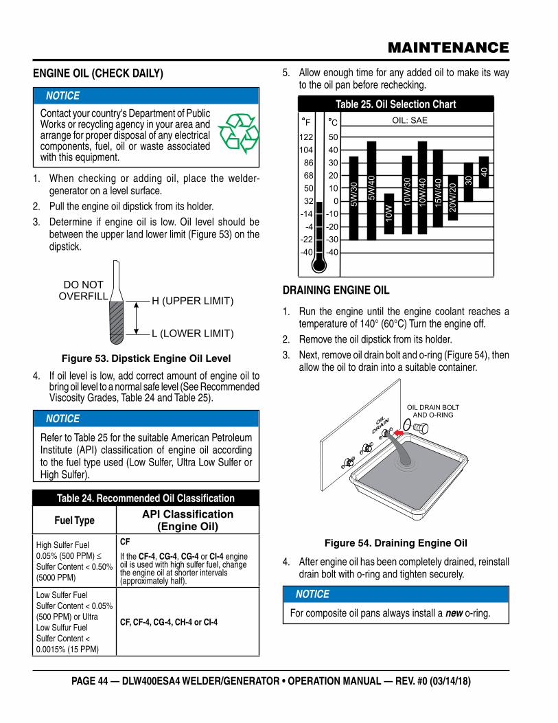
PAGE 44 — DLW400ESA4 WELDER/GENERATOR • OPERATION MANUAL — REV. #0 (03/14/18)
ENGINE OIL (CHECK DAILY)
1. When checking or adding oil, place the welder-generator on a level surface.
2. Pull the engine oil dipstick from its holder.3. Determine if engine oil is low. Oil level should be
between the upper land lower limit (Figure 53) on the dipstick.
Figure 53. Dipstick Engine Oil Level
4. If oil level is low, add correct amount of engine oil to bring oil level to a normal safe level (See Recommended Viscosity Grades, Table 24 and Table 25).
NOTICE
Contact your country's Department of Public Works or recycling agency in your area and arrange for proper disposal of any electrical components, fuel, oil or waste associated with this equipment.
H (UPPER LIMIT)
L (LOWER LIMIT)
DO NOTOVERFILL
NOTICE
Refer to Table 25 for the suitable American Petroleum Institute (API) classification of engine oil according to the fuel type used (Low Sulfer, Ultra Low Sulfer or High Sulfer).
Table 24. Recommended Oil Classification
Fuel Type API Classification (Engine Oil)
High Sulfer Fuel 0.05% (500 PPM) ≤ Sulfer Content < 0.50% (5000 PPM)
CF
If the CF-4, CG-4, CG-4 or CI-4 engine oil is used with high sulfer fuel, change the engine oil at shorter intervals (approximately half).
Low Sulfer Fuel Sulfer Content < 0.05% (500 PPM) or Ultra Low Sulfur Fuel Sulfer Content < 0.0015% (15 PPM)
CF, CF-4, CG-4, CH-4 or CI-4
MAINTENANCE
5. Allow enough time for any added oil to make its way to the oil pan before rechecking.
Table 25. Oil Selection Chart
DRAINING ENGINE OIL
1. Run the engine until the engine coolant reaches a temperature of 140° (60°C) Turn the engine off.
2. Remove the oil dipstick from its holder.3. Next, remove oil drain bolt and o-ring (Figure 54), then
allow the oil to drain into a suitable container.
Figure 54. Draining Engine Oil
4. After engine oil has been completely drained, reinstall drain bolt with o-ring and tighten securely.
-40
-30
-10
-20
-22
-40
-4
-14
032
50
68
86
104
122
10
20
30
40
50
F C
5W
/30
5W
/40
10W
10W
/30
10W
/40
15W
/40
20W
/20 3
0
40
OIL: SAE
OIL
DR
AIN
OIL DRAIN BOLTAND O-RING
NOTICE
For composite oil pans always install a new o-ring.

DLW400ESA4 WELDER/GENERATOR • OPERATION MANUAL — REV. # 0 (03/14/18) — PAGE 45
ENGINE OIL FILTER REPLACEMENT
1. Clean the area around the lubricating oil filter head.2. Using an oil filter wrench (Figure 55), remove engine
oil filter.
Figure 55. Engine Oil Filter Removal
3. Coat the rubber seal (gasket) surface of oil filter (Figure 55) with clean 15W-40 engine oil.
4. Install new oil filter first by hand until it makes contact with the filter head surface. Tighten it another 3/4 turn using the filter wrench.
5. Fill engine crankcase with high quality detergent oil as referenced in Table 25. Fill to the upper limit of dipstick. DO NOT overfill. Reference Table 4 for engine crankcase oil capacity.
6. Run the engine for several minutes. Watch for oil leakage. Shut the engine down and allow it to sit for several minutes. Top off the oil to the upper limit on the dipstick.
ENGINEOIL FILTER
CARTRIDGE
RUBBERSEAL
COAT SEALWITH THIN
LAYER OF OILOIL FILTER WRENCH
OIL
MAINTENANCE
DRAINING ENGINE COOLANT
1. Remove the radiator pressure cap (Figure 56) only if the coolant tempeature is below 120°F (50°C).
Figure 56. Radiator Pressure Cap Removal
2. Remove the coolant drain bolt and o-ring (Figure 57), then allow the coolant to drain into a suitable container.
Figure 57. Draining Radiator Coolant
3. Check hoses for softening and kinks. Check clamps for signs of leakage.
4. Remove and inspect radiator cap.
WARNING
DO NOT remove the pressure cap from the radiator when the engine is hot! Wait until the coolant temperature is below 120°F (50°C) before removing pressure cap.
Heated coolant spray or steam can cause severe scalding and personal injury.
°F
WATER TEMP
100
140180
220
260
°F
WATER TEMP
100
140180
220
260
CORRECT
PRESSURECAP
COOLANT DRAIN BOLTAND O-RING
COOLANT
DRAIN

PAGE 46 — DLW400ESA4 WELDER/GENERATOR • OPERATION MANUAL — REV. #0 (03/14/18)
MAINTENANCE
FLUSHING OUT RADIATOR AND REPLACING COOLANT
1. Remove radiator cap.
2. Remove the coolant drain bolt and o-ring (Figure 57), then allow the coolant to drain into a suitable container
3. If equipped, remove the overflow tank. Drain and clean overflow tank.
4. Replace the overflow tank if necessary.
5. Check hoses for softening and kinks. Check clamps for signs of leakage.
6. Flush the radiator by running clean tap water through radiator until signs of rust and dirt are removed. DO NOT clean radiator core with any objects, such as a screwdriver.
7. Replace with coolant as recommended by the engine manufacturer. Reference Table 4 for coolant capacity.
8. Reinstall coolant drain bolt with o-ring and tighten securely.
COOLANT (ANTIFREEZE/SUMMER COOLANT/WATER)
Kubota recommends antifreeze/summer coolant for use in their engines, which can be purchased in concentrate (and mixed with 50% demineralized water) or pre-diluted. See the Kubota Operation and Maintenance Manual for further details.
WARNING
DO NOT remove the pressure cap from the radiator when the engine is hot! Wait until the coolant temperature is below 120°F (50°C) before removing pressure cap.
Heated coolant spray or steam can cause severe scalding and personal injury.
WARNING
If adding coolant/antifreeze mix to the radiator, DO NOT remove the radiator cap until the unit has completely cooled. The possibility of hot! coolant exists which can cause severe burns.
Day-to-day addition of coolant is done via the radiator. When adding coolant to the radiator, DO NOT remove the radiator pressure cap until the unit has completely cooled. Reference Table 4 for coolant capacity.
OPERATION IN FREEZING WEATHER
When operating in freezing weather, be certain the proper amount of antifreeze has been added as referenced in Table 26.
RADIATOR CLEANING
The radiator (Figure 58) should be sprayed (cleaned) with a high pressure washer when excessive amounts of dirt and debris have accumulated on the cooling fins or tube. When using a high pressure washer, stand at least 5 feet (1.5 meters) away from the radiator to prevent damage to the fins and tube.
Figure 58. Radiator Cleaning
Table 26. Anti-Freeze Operating Temperatures
Vol % Anti-
Freeze
Freezing Point Boiling Point
°C °F °C °F
50 -37 -34 108 226

DLW400ESA4 WELDER/GENERATOR • OPERATION MANUAL — REV. # 0 (03/14/18) — PAGE 47
Removing Water from the Fuel Tank
1. After prolonged use, water and other impurities accumulate in the bottom of the tank. Occasionally inspect the fuel tank for water contamination.
2. If water contamination is present within the fuel tank, remove the fuel tank drain bolt and o-ring (Figure 59), then allow the fuel to drain into a suitable container.
Figure 59. Draining Fuel Tank
3. During cold weather, the more empty volume inside the tank, the easier it is for water to condense. This can be reduced by keeping the tank full with diesel fuel.
CLEANING INSIDE THE FUEL TANK
1. If necessary, drain the fuel inside the fuel tank completely. Using a spray washer (Figure 60) wash out any deposits or debris that have accumulated inside the fuel tank.
FU
EL
DR
AIN
FUEL DRAIN BOLTAND O-RING
MAINTENANCE
Figure 60. Fuel Tank Cleaning
2. Reinstall fuel tank drain bolt with o-ring and tighten securely.
FUEL TANK INSPECTION
In addition to cleaning the fuel tank, the following components should be inspected for wear:
� Fuel Hoses — inspect nylon and rubber hoses for signs of wear, deterioration and hardening.
� Fuel Tank Lining — inspect the fuel tank lining for signs of excessive amounts of oil or other foreign matter.
CLEANING FUEL FILTER BOWL
Every 100 hours: Clean fuel filter every 100 hours of operation or once a month to remove dust or water.
1. Place fuel valve lever (Figure 61) in the CLOSED position.
Figure 61. Fuel Valve Lever (CLOSED)
FUEL TANK
OFF
ON

PAGE 48 — DLW400ESA4 WELDER/GENERATOR • OPERATION MANUAL — REV. #0 (03/14/18)
MAINTENANCE
2. Unscrew the filter bowl (Figure 62) from the fuel filter head.
Figure 62. Fuel Filter Disassembly
3. Wipe the inside of the fuel filter bowl with a clean cloth to remove any foreign matter or debris that may have accumulated. Rinse with diesel fuel.
4. Remove fuel filter paper element, and rinse with diesel fuel.
5. Reinstall filter bowl and paper element back onto the filter head. Hand-tighten retaining ring.
REPLACING FUEL FILTER ELEMENT
First 50 And Then Every 200 hours: Replace fuel filter element.
1. Unscrew the f i l ter bowl from the fuel f i l ter head (Figure 62).
2. Remove fuel filter paper element and replace with a new one.
3. Replace o-ring and coat with a small amount of clean 15W-40 engine oil.
4. Insert the new fuel filter element into the filter bowl.
5. Reinstall filter bowl first by hand until it makes contact with the fuel filter head surface. Hand-tighten only.
6. Remove the air from the fuel system. Reference the Kubota Operation and Maintenance Manual, "Bleeding the Fuel System".
PAPERELEMENT
SPRING
O-RING
FILTERBOWL
RETAININGRING
FILTERHEAD
O-RING
AUTOMATIC AIR BLEEDING DEVICE
When the engine stops due to running out of fuel, take off the fuel filter or fuel piping and re-start the machine in accordance with the following instructions.
1. Refuel the fuel tank and place the fuel valve in the OPEN position.
2. Place the starter switch key in the START position. When the engine starter engages, the automatic air vent device will expel the air inside the fuel system.
3. After 10 to 20 seconds of turning the engine over, the automatic air vent device would have expelled all the air out of the fuel system. At this point, the engine will be able to start.
STOPPING ENGINE (STARTER SWITCH FAILURE)
In the event the engine continues to run even after the starter switch has been placed in the STOP position, following the procedure on the next column to turn off the engine.
1. Place fuel valve lever (Figure 61) in the CLOSED position.
2. Place engine stop lever (Figure 63) in the STOP position. Continue pushing stop lever until the engine has completely stopped.
Figure 63. Engine Stop Lever
NOTICE
If air enters the fuel injection system of a diesel engine, starting becomes impossible. After running out of fuel, or after disassembling the fuel system, bleed the system.Reference the Kubota Operation and Maintenance Manual for details.
PUSH
STOP
POSITION
ENGINE
STOP LEVER

DLW400ESA4 WELDER/GENERATOR • OPERATION MANUAL — REV. # 0 (03/14/18) — PAGE 49
V-BELT
Visually examine the V-belt (Figure 64) and determine if it is full of tiny cracks, frayed, has pieces of rubber missing, is peeling or otherwise damaged.
Also, examine the belt and determine if it is oil soaked or "glazed" (hard shiny appearance on the sides of the belt). Either of these two conditions can cause the belt to run hot, which can weaken it and increase the danger of it breaking.
If the V-belt exhibits any of the above wear conditions replace the V-belt immediately.
Figure 64. V-Belt Inspection
TESTING THE GFCI SENSING MODULE
If tripping of the main circuit breaker persists after a load is replaced with a known good one (no short circuit), perform this test with no load.
1. Start the welder-generator as outlined in the start up procedure in this manual.
2. Place the main circuit breaker, CB1 (Figure 65) in the ON position.
Figure 65. Main Circuit Breaker ON (GFCI Test)
GLAZED
OIL SOAKED
BROKEN
CORD FAILURE
CRACKSMISSING RUBBER
SIDEWALLWEAR
WORN BACKCOVER
40 AAC220V 25kA
PSE
JET
Fe
CB1ON
MAINTENANCE
3. On the GFCI sensing module (Figure 66), verify that the green POWER LED is ON.
Figure 66. GFCI Sensing Module (Green LED ON)
4. Also verify that the AC voltmeter is registering a voltage reading as indicated by Figure 71.
5. Next, press the TEST button on the GFCI module (Figure 67) and verify that the green POWER LED turns OFF and the red FAULT LED turns ON.
Figure 67. GFCI Sensing Module (Red/Fault LED ON)
6. Also verify that the main circuit breaker (Figure 68) switch trips to the OFF position.
Figure 68. Circuit Breaker OFF (GFCI Test)
MANUAL RESET
P
O
W
E
R
F
A
U
L
T
GREEN
POWER
LED
MANUAL RESET
P
O
W
E
R
F
A
U
L
T
PRESS
RED
FAULT
LED
OFF
40 AAC220V 25kA
PSE
JET
Fe
CB1

PAGE 50 — DLW400ESA4 WELDER/GENERATOR • OPERATION MANUAL — REV. #0 (03/14/18)
MAINTENANCE
7. Verify that the AC voltmeter (Figure 69) on the welder-generator reads zero volts.
Figure 69. AC Voltmeter (Zero Volts)
8. To restore power, press the RESET button (Figure 70) on the GFCI module and verify that the red FAULT LED turns OFF and the green POWER LED should turn ON.
Figure 70. GFCI Sensing Module (Green LED ON Reset)
9. Verify that the AC voltmeter is registering a voltage reading as indicated by Figure 71.
Figure 71. AC Voltmeter (120/240V)
V
0
050
100300
150
200
100
MANUAL RESET
P
O
W
E
R
F
A
U
L
T
PRESS
GREEN
POWER
LED
V
0
050
100
300
150
200
100
NOTICE
It is recommended that the GFCI sensing module be tested when the welder-generator is initially uncrated. Then, the module should be tested daily at startup.
TESTING THE GFCI RECEPTACLE
If tripping of the GFCI receptacle persists after a load is replaced with a known good one (no short circuit), perform this test at least once a month.
1. Start the welder-generator as outlined in the start up procedure in this manual.
2. Place the GFCI circuit breaker, CB4 (Figure 72) in the ON position.
Figure 72. GFCI Circuit Breaker ON
3. Verify green LED on the GFCI receptacle (Figure 73)is ON.
4. Plug a power tool into the GFCI receptacle such as a electric drill. Squeeze the ON/OFF switch on the drill and verify that the drill turns on.
Figure 73. GFCI Receptacle Test
CAUTION
The GFCI module is designed to interrupt power when a ground fault exists to prevent injuries and shock hazards. DO NOT operate the welder-generator if this test fails. Consult a qualified electrician for repair or replacement of the GFCI module.
20A120V
No.4
CB4
ON
GREEN LED ON
GFCIRECEPTACLE
ELECTRICDRILL
ON/OFFSWITCH
TESTBUTTON
RESETBUTTON

DLW400ESA4 WELDER/GENERATOR • OPERATION MANUAL — REV. # 0 (03/14/18) — PAGE 51
5. Continue holding down the ON/OFF switch on the drill and at the same time press the TEST button on the GFCI receptacle.
6. Verify that the drill turns off when the TEST button was pressed.
7. If the drill motor continues to run after the TEST button was pressed then it can be determined that the GFCI receptacle is not working properly and should be replaced.
8. Press the RESET button to restore power to the GFCI receptacle.
PROTECTION DEVICES
1. This unit is equipped with protection devices. When any of the major protection devices are activated, the engine will automatically stop and the error code message will be displayed on the DC welding current meter (Figure 74).
Figure 74. DC Weld Meter Error Codes
NOTICE
Low oil pressure, high coolant temperature, high engine speed and battery charge are considered major protection parameters and will cause the engine to shutdown.
DC WELD METER
TERMINAL: A TERMINAL: B
AV
Welding Welding
AV
MAINTENANCE
2. In addition, the battery charge, oil pressure and water temperature alarms will be displayed on the engine warning display (Figure 75).
Figure 75. Engine Warning Lamps
3. Reference Table 27 for protection device error codes.
GENERATOR SIDE
If the power transistor (PTR), insulated-gate bipolar transistor (IGBT) on the welding side become abnormally hot, a protective error code will be displayed on the DC welding current meter. This condition will cause the welding to stop, but will not shutdown the engine.
An error code of E10 will be displayed on the terminal A side, while an error code of E20 will be displayed on the terminal B side.
The cause of these two error codes (E10/E20) is due to an overload condition on the welding side (duty cycle over the limit) or insufficient cooling due to an open cabinet door or blocked air intake. Take corrective action on these conditions and welding will resume when the PTR (IGBT) cools down.
FUSES
The engine wiring system has its own fuses (F2 and F5). If either of these fuses are blown, check the wiring to determine if an electrical short circuit exists. Correct the problem before installing new fuses.
WARNING LAMP

PAGE 52 — DLW400ESA4 WELDER/GENERATOR • OPERATION MANUAL — REV. #0 (03/14/18)
GENERATOR WIRING DIAGRAM (S/N573486 AND BELOW)
23.5
: 3.5
mm
2
5.5
: 5.5
mm
2
8: 8 m
m
2 14: 14 m
m
2 30: 30 m
m
2 m
m
B L BR
G GR
V P
BLA
CK
BLU
EB
RO
WN
GR
EE
NG
RA
YV
IOLE
TP
INK
R W Y LB
LG
O
RE
DW
HIT
EY
ELLO
WLIG
HT
BLU
ELIG
HT
GR
EE
NO
RA
NG
E
WIR
E S
IZE
CO
DE
/WIR
E C
OL
OR
NO
MA
RK
WIR
E S
IZE
: 0.7
5
Term
ina
l Bo
ard
(With
En
gin
e S
ide
)
TB
2
TB
1

DLW400ESA4 WELDER/GENERATOR • OPERATION MANUAL — REV. # 0 (03/14/18) — PAGE 53
CONNECTOR ARRANGEMENT
(VIEW FROM WIRING SIDE)
GCB1
CON 1
L A, B
THA, BC1, 2 A, B
BRUSHLESS GENERATOR
AC. VOLTMETER
TERMINAL BOARD
DC WELDING TERMINALDC REACTOR
PROTECTOR TRANSISTOR (IGBT)
CURRENT TRANSFORMER
IGBT
RECTIFIER
CONDENSER
THERMOSTATRECTIFIER
IP A, B
PTR A, B
CT-A, B
Re1 A, B
Re2
DIGITAL PANELDM-76
SYMBOL DESIGNATION
CB2CB3CB4
CON 2CON 3CON 4
V~
TB1
AVR
SW1
C2~5
VR2 A, B
VR1 A, B
VR3
SW2SW3SW5SW6SW7SW8RSGMR1
R2 A, B
R4 A, B
RY1
OCR
TB2
22
CIRCUIT BREAKER, 3P 40ACIRCUIT BREAKER, 2P 30ACIRCUIT BREAKER, 1P 30ACIRCUIT BREAKER, 2P 20A
RECEPTACLE, GFCI 5-20R, 125 VAC @ 20 AMPS
RECEPTACLE, CS6369, 250 VAC@ 50 AMPSRECEPTACLE, L6-30R, 250 VAC@ 30 AMPSRECEPTACLE, L5-30R, 125 VAC@ 30 AMPS
IC CONTROL UNIT, TRANSISTOR (IGBT)
CURRENT TRANSFORMERCT-AC
AUTOMATIC VOLTAGE REGULATOR
CONDENSER
CURRENT/VOLTAGE REGULATOR
WELDING REGULATION
TIME REGULATOR
IDLE STOP SELECTOR SWITCH
E-MODE SELECTOR SWITCH
WELDING MODE SELECTOR SWITCHDOOR SWITCH
LIMIT SWITCHENGINE START PUSHBUTTON SWITCHSINGLE-DUAL SELECTOR SWITCH
ROTATION SENSORGEARED MOTOR
RESISTORRESISTOR
RESISTOR
RELAY
OVER CURRENT RELAY
TERMINAL BOARD
GROUND TERMINAL FOR GFCI
SOCKET
GFCI SENSING MODULE
CONNECTOR REFERENCE DESIGNATORS
GENERATOR WIRING DIAGRAM (S/N573486 AND BELOW)

PAGE 54 — DLW400ESA4 WELDER/GENERATOR • OPERATION MANUAL — REV. #0 (03/14/18)
GENERATOR WIRING DIAGRAM (S/N573487 AND ABOVE)
23.5
: 3.5
mm
2
5.5
: 5.5
mm
2
8: 8 m
m
2 14: 14 m
m
2 30: 30 m
m
2 m
m
B L BR
G GR
V P
BLA
CK
BLU
EB
RO
WN
GR
EE
NG
RA
YV
IOLE
TP
INK
R W Y LB
LG
O
RE
DW
HIT
EY
ELLO
WLIG
HT
BLU
ELIG
HT
GR
EE
NO
RA
NG
E
WIR
E S
IZE
CO
DE
/WIR
E C
OL
OR
NO
MA
RK
WIR
E S
IZE
: 0.7
5
Term
ina
l Bo
ard
(With
En
gin
e S
ide
)
TB
2
TB
1

DLW400ESA4 WELDER/GENERATOR • OPERATION MANUAL — REV. # 0 (03/14/18) — PAGE 55
GENERATOR WIRING DIAGRAM (S/N573487 AND ABOVE)
CONNECTOR ARRANGEMENT
(VIEW FROM WIRING SIDE)
GCB1
CON 1
L A, B
THA, BC1, 2 A, B
BRUSHLESS GENERATOR
AC. VOLTMETER
TERMINAL BOARD
DC WELDING TERMINALDC REACTOR
PROTECTOR TRANSISTOR (IGBT)
CURRENT TRANSFORMER
IGBT
RECTIFIER
CONDENSER
THERMOSTATRECTIFIER
IP A, B
PTR A, B
CT-A, B
Re1 A, B
Re2
DIGITAL PANELDM-77
SYMBOL DESIGNATION
CB2CB3CB4
CON 2CON 3CON 4
V~
TB1
AVR
SW1
C2~5
VR2 A, B
VR1 A, B
VR3
SW2SW3SW5SW6SW7SW8RSGMR1
R2 A, B
R4 A, B
RY1, 2
OCR
TB2
22
CIRCUIT BREAKER, 3P 40ACIRCUIT BREAKER, 2P 30A
CIRCUIT BREAKER, 1P 30ACIRCUIT BREAKER, 2P 20A
RECEPTACLE, GFCI 5-20R, 125 VAC @ 20 AMPS
RECEPTACLE, CS6369, 250 VAC@ 50 AMPSRECEPTACLE, L6-30R, 250 VAC@ 30 AMPSRECEPTACLE, L5-30R, 125 VAC@ 30 AMPS
IC CONTROL UNIT, TRANSISTOR (IGBT)
CURRENT TRANSFORMERCT-AC
AUTOMATIC VOLTAGE REGULATOR
CONDENSER
CURRENT/VOLTAGE REGULATOR
WELDING REGULATION
TIME REGULATOR
IDLE STOP SELECTOR SWITCH
E-MODE SELECTOR SWITCH
WELDING MODE SELECTOR SWITCHDOOR SWITCH
LIMIT SWITCHENGINE START PUSHBUTTON SWITCHSINGLE-DUAL SELECTOR SWITCH
ROTATION SENSORGEARED MOTOR
RESISTORRESISTOR
RESISTOR
RELAY
OVER CURRENT RELAY
TERMINAL BOARD
GROUND TERMINAL FOR GFCI
SOCKET
GFCI SENSING MODULE
CONNECTOR REFERENCE DESIGNATORS

PAGE 56 — DLW400ESA4 WELDER/GENERATOR • OPERATION MANUAL — REV. #0 (03/14/18)
ENGINE WIRING DIAGRAM
21
25
: 1
25
mm
2
2:
2 m
m
2
3:
3
mm
2
2
2:
2
2 m
m
2 m
m
B L BR
G GR
V P
BL
AC
KB
LU
EB
RO
WN
GR
EE
NG
RA
YV
IOL
ET
PIN
K
R W Y LB
LG
O
RE
DW
HIT
EY
EL
LO
WL
IGH
T B
LU
EL
IGH
T G
RE
EN
OR
AN
GE
WIR
E S
IZE
CO
DE
/WIR
E C
OL
OR
NO
MA
RK
WIR
E S
IZE
: 0
.75
RY
5R
Y6
Re3
PLSW
9
STA
RTE
R T
ELA
Y
GLO
W R
ELA
YE
NG
INE
ON
/OFF
RE
LAY
PO
WE
R R
ELA
Y
STA
RTE
R S
WIT
CH
RE
CTI
FER
PIL
OT
LAM
P
SY
MB
OL
DE
SIG
NA
TIO
N
RY
7R
Y8

DLW400ESA4 WELDER/GENERATOR • OPERATION MANUAL — REV. # 0 (03/14/18) — PAGE 57
Table 27. Error CodesError Code [1] Error Details Corrective Action
E01Low Lubricating Oil Pressure, below 0.98 MPa (Engine Shutdown/Warning Lamp ON)
• Check oil level.
• Check oil pressure.
E02High Jacket Water Temp., > (239 °F) 115° C (Engine Shutdown/Warning Lamp ON)
• Check coolant level (after machine has cooled down).
• Check air breathing and exhaust vents are not clogged.
• Check for thermal effect of any other machines.
E03Insufficient Charge (Engine Shutdown/Warning Lamp ON)
• If engine is stopped due to lack of fuel or clogged filters, error code E03 will be indicated, although no insufficient charge condition exists. (E01 may be indicated due to decision timing of engine emergency circuit).
• Battery not charged, loose battery connections.
• Fan belt loose or broken.
E04 Engine Over-Speed (Engine Shutdown) • Engine speed too high, > 4140 rpm's. Reduce speed.
E06Starting Failure Engine Shutdown
• Add fuel to engine. Set fuel cock to ON
• Inspect fuel tank and fuel filter for water or deposits.
• Check battery liquid level and charging level.
• Inspect fan belt for looseness.
• Check fuses F2 and F5.
E10A-Side PTR (IGBT) Overheat (Welding Shutdown/Self Recovery)
• Check air breathing and exhaust vents are not clogged.
• Check for thermal effect of any other machines.
• Make sure side door is closed before operation.
E13 A-Side Welding Overcurrent • Allow for proper duty cycle. Reference Table 7.
E16 A-Side Current/Voltage Regulator Error • Inspect regulator movement and connections.
E17 A-Side Welding Regulator Error • Inspect, remove and test regulator for proper resistance.
E20B-Side PTR (IGBT) Overheat (Welding Shutdown/Self Recovery)
• Check air and exhaust vents are not clogged.
• Check for thermal effect of any other machines.
• Make sure side door is closed before operation.
E23 B-Side Welding Overcurrent • Allow for proper duty cycle. Reference Table 7.
E26 B-Side Current/Voltage Regulator • Inspect regulator movement and connections.
E27 B-Side Welding Regulator Error • Inspect, remove and test regulator for proper resistance.
E30 Idling Stop Regulator Error • Inspect regulator movement and connections.
E33Communication Error (Receiving Error At Display Board)
• Inspect intergrated circuit (IC) and digtal meter (DM) board connections.
E34Communication Error (Receiving Error At Control Board)
• Inspect intergrated circuit (IC) and control board (CB) connections.
IdS (blinking) Idling Stop Function Disabled • Check idle stop monitor status LED's
[1] : An error condition displayed with an asterisk (*) cannot always be corrected via simple inspection.Please contact Multiquip Service Dept. or your MQ Service Dealer for assistance.
WELDER-GENERATOR — ERROR CODES

PAGE 58 — DLW400ESA4 WELDER/GENERATOR • OPERATION MANUAL — REV. #0 (03/14/18)
WELDER-GENERATOR — TROUBLESHOOTING
Table 28. Troubleshooting (Welder-Generator)Symptom Possible Problem Solution
Starter switch is set to RUN but engine does not start.
Engine Start button has not been pushed? Push Engine Start button.
“IdS” is indicated on welding current meter display.
Welding preset time (1–30 minutes) has ben reached when using the idle stop function?
Restart engine from idle stop in any of the restarting methods, or set the starter switch to STOP once, then to RUN again and push the Engine Start button to start the engine.
No indication appears on welding current meter display though Starter switch is set to RUN. (Restart from idle stop is not possible.)
As engine has not been operated for 3 hours, automatic control power cut function is working?
If Engine Start button is not pushed while Starter switch remains at RUN position, or if idle stop state continues 2 hours or more, control power will automatically be cut off. (Operation lamp lights to remind operator to set to OFF.)
When restarting engine, set the Starter switch to STOP once, then to RUN again and push the Engine Start button.
Idle stop function does not operate. (Main CB indicator lamp on idle stop monitor is ON.)
Idle Stop switch is set to OFF? Set Idle Stop switch to the ON position to enable the idle stop function.
Idle stop preset time has not elapsed?
Idle stop is made after preset time elapses following a pause in work with welding power or output receptacle power (120V GFCI).
Welding indicator lamp on welding current meter lights while welding work is performed. AC Load lamp on idle stop monitor lights when AC power is used.
Charging time for battery is secured?
Just after engine start, idle stop is not made to charge battery. During charging time, Restart Charge lamp on idle stop monitor lights to indicate automatic stop is limited. Stop limit time varies with time idle stop is operated.
Main AC circuit breaker (CB1) is set to the ON position?
Place Main AC circuit breaker (CB1) to the OFF position.

DLW400ESA4 WELDER/GENERATOR • OPERATION MANUAL — REV. # 0 (03/14/18) — PAGE 59
WELDER-GENERATOR — TROUBLESHOOTING (CONT.)
Table 29. Troubleshooting (Welder-Generator)Symptom Possible Problem Solution
Engine cannot be restarted from idle stop.
Idle Stop switch is set to OFF?Make sure Idle Stop switch is in the ON position, then push the Engine Start button to start engine.
Short-circuit and release between welding material and welding electrode cannot be detected twice or more?
If welding electrode and surface of welding material conduct current poorly due to rust or coating, or if welding electrode is continuously short-circuited by pressing it onto welding material, or if tapping intervals are too short or too long, voltage varying signal for restart may not be detected.
“IdS” indication blinks on the welding current meter while welding electrode is being short-circuited.)
Engine cannot be restarted from idle stop. (“IdS” and preset current value are indicated alternately on welding current meter and indicator lamp on idle stop monitor is blinking.)
Main circuit breaker (CB1) and auxil iary AC circuit breakers (CB2, CB3 and CB4) are set to the ON position?
Place all circuit breakers to OFF position. AC Load lamp on idle stop monitor blinks if AC auxiliary circuit breakers are ON.
Side door open?Close side door. Side Door Open lamp on idle stop monitor blinks if side door is open.
ON/OFF power swi tch f rom load (power tool) connected to 120V GFCI receptacle cannot be detected twice or more?
If power switch of the load connected to output receptacle remains ON, AC Load lamp on idle stop monitor blinks to prevent restart for safety. Set switch to ON then OFF twice or more and wait with switch in OFF position until engine restarts.
Engine RPM fluctuates higher or lower during welding.
Automatic control of engine revolutions responding to welding output and preset frequency of AC power in use is functioning?
If E-mode switch is set to Variable/Low position, engine revolutions are controlled based on preset value of welding current. Engine revolutions are adjusted up or down to meet total output for 2 operators.
If AC power is used by 2 persons simultaneously, engine will operate at high speed because preset AC frequency is outputted.
Semiconductor is overheated?
If the side-door is open or exhaust vents are clogged, causing insufficient cooling; if semiconductors are heated at an over-duty rate, output is limited to prevent such overheating.
AC power is not available. AC circuit breakers are not set to ON?
Place all circuit breakers CB1, CB2, CB3, and CB4 to the ON position.

PAGE 60 — DLW400ESA4 WELDER/GENERATOR • OPERATION MANUAL — REV. #0 (03/14/18)
WELDER-GENERATOR — TROUBLESHOOTING (CONT.)
Table 27. Troubleshooting (Welder-Generator)Symptom Possible Problem Solution
Welding current does not match preset value.
Welding regulator is turned clockwise from constant current position for welding?
Adjust welding regulator to position at which customer's welding work is easy. Constant current position is adjusted to preset current value, but if welding regulator is set to any other position, drooping characteristic appears.
Welding current may drop depending upon diameter and length of welding cable and may also vary depending upon type, thickness, and arc length of welding electrode. (Current variation is larger as welding regulator is turned further clockwise.)
Consider indicated preset current value as standard at any position other than constant current position.
Rotation speed of engine is low due to overload or being out of condition?
When welding at maximum output, output may be limited by overload if welding cable diameter is too thin or welding cable length is too long. Use cable within recommended range for welding work.
If total output is overloaded when using AC power and welding simultaneously, output will be limited. Be careful not to cause an overload.
Semiconductor is overheated?
If the side-door is open or exhaust vents are clogged, causing insufficient cooling; if semiconductors are heated at an over-duty rate, output is limited to prevent such overheating.

DLW400ESA4 WELDER/GENERATOR • OPERATION MANUAL — REV. # 0 (03/14/18) — PAGE 61
NOTES
OPERATION MANUAL
Your Local Dealer is:
HERE’S HOW TO GET HELPPLEASE HAVE THE MODEL AND SERIAL
NUMBER ON-HAND WHEN CALLING
UNITED STATESMultiquip Corporate Office MQ Parts Department
18910 Wilmington Ave.Carson, CA 90746 Contact: [email protected]
Tel. (800) 421-1244Fax (310) 537-3927
800-427-1244310-537-3700
Fax: 800-672-7877
Service Department Warranty Department
800-421-1244310-537-3700
800-421-1244310-537-3700
Fax: 310-943-2249
Technical Assistance
800-478-1244 Fax: 310-943-2238
CANADA UNITED KINGDOM
Multiquip (UK) Limited Head OfficeMultiquip
4110 Industriel Boul.Laval, Quebec, Canada H7L 6V3 Contact: [email protected]
Tel: (450) 625-2244 Tel: (877) 963-4411Fax: (450) 625-8664
Unit 2, Northpoint Industrial Estate, Globe Lane,Dukinfield, Cheshire SK16 4UJContact: [email protected]
Tel: 0161 339 2223 Fax: 0161 339 3226
© COPYRIGHT 2018, MULTIQUIP INC.
Multiquip Inc , the MQ logo and the MQ Power logo are registered trademarks of Multiquip Inc. and may not be used, reproduced, or altered without written permission. All other trademarks are the property of their respective owners and used with permission.
This manual MUST accompany the equipment at all times. This manual is considered a permanent part of the equipment and should remain with the unit if resold.
The information and specifi cations included in this publication were in effect at the time of approval for printing. Illustrations, descriptions, references and technical data contained in this manual are for guidance only and may not be considered as binding. Multiquip Inc. reserves the right to discontinue or change specifi cations, design or the information published in this publication at any time without notice and without incurring any obligations.
Manufactured for Multiquip Inc.
byDENYO CO., LTD, JAPAN