model for the structure of round-strand wire … · model for the structure of round-strand wire...
TRANSCRIPT

RI 9644 REPORT OF INVESTIGATIONS/1998
Model for the Structure of Round-StrandWire Ropes
U.S. DEPARTMENT OF HEALTH AND HUMAN SERVICESPublic Health Service
Centers for Disease Control and Prevention
National Institute for Occupational Safety and Health

Cover: Paths of three types of double helical wires ina 6×19 Seale, IWRC, right regular lay wire ropelooking down the rope axis.


Report of Investigations 9644
Model for the Structure of Round-Strand Wire Ropes
Richard C. Wang, Anthony J. Miscoe, and William M. McKewan
U.S. DEPARTMENT OF HEALTH AND HUMAN SERVICESPublic Health Service
Centers for Disease Control and Prevention
National Institute for Occupational Safety and Health
Pittsburgh Research Laboratory
Pittsburgh, PA
September 1998

International Standard Serial NumberISSN 1066-5552

CONTENTSPage
Abstract. . . . . . . . . . . . . . . . . . . . . . . . . . . . . . . . . . . . . . . . . . . . . . . . . . . . . . . . . . . . . . . . . . . . . . . . . . . . . . . . . . . 1Introduction. . . . . . . . . . . . . . . . . . . . . . . . . . . . . . . . . . . . . . . . . . . . . . . . . . . . . . . . . . . . . . . . . . . . . . . . . . . . . . . . 2Description of rope structure. . . . . . . . . . . . . . . . . . . . . . . . . . . . . . . . . . . . . . . . . . . . . . . . . . . . . . . . . . . . . . . . . . . 2
Structural elements. . . . . . . . . . . . . . . . . . . . . . . . . . . . . . . . . . . . . . . . . . . . . . . . . . . . . . . . . . . . . . . . . . . . . . . . 2Classification of wires. . . . . . . . . . . . . . . . . . . . . . . . . . . . . . . . . . . . . . . . . . . . . . . . . . . . . . . . . . . . . . . . . . . . . 3Structural parameters. . . . . . . . . . . . . . . . . . . . . . . . . . . . . . . . . . . . . . . . . . . . . . . . . . . . . . . . . . . . . . . . . . . . . . 3
Mathematical modeling. . . . . . . . . . . . . . . . . . . . . . . . . . . . . . . . . . . . . . . . . . . . . . . . . . . . . . . . . . . . . . . . . . . . . . . 4Basic relationships. . . . . . . . . . . . . . . . . . . . . . . . . . . . . . . . . . . . . . . . . . . . . . . . . . . . . . . . . . . . . . . . . . . . . . . . 4Coordinate systems. . . . . . . . . . . . . . . . . . . . . . . . . . . . . . . . . . . . . . . . . . . . . . . . . . . . . . . . . . . . . . . . . . . . . . . 5Vector equations for single and double helices. . . . . . . . . . . . . . . . . . . . . . . . . . . . . . . . . . . . . . . . . . . . . . . . . . . 5
Single helix model. . . . . . . . . . . . . . . . . . . . . . . . . . . . . . . . . . . . . . . . . . . . . . . . . . . . . . . . . . . . . . . . . . . . . . 5Double helix model. . . . . . . . . . . . . . . . . . . . . . . . . . . . . . . . . . . . . . . . . . . . . . . . . . . . . . . . . . . . . . . . . . . . . 6
Example for a specific wire rope. . . . . . . . . . . . . . . . . . . . . . . . . . . . . . . . . . . . . . . . . . . . . . . . . . . . . . . . . . . . . 7Model applications. . . . . . . . . . . . . . . . . . . . . . . . . . . . . . . . . . . . . . . . . . . . . . . . . . . . . . . . . . . . . . . . . . . . . . . . . . 10
Generation of wire paths. . . . . . . . . . . . . . . . . . . . . . . . . . . . . . . . . . . . . . . . . . . . . . . . . . . . . . . . . . . . . . . . . . . 10Evaluation of geometric properties. . . . . . . . . . . . . . . . . . . . . . . . . . . . . . . . . . . . . . . . . . . . . . . . . . . . . . . . . . . . 12
Path length per lay of strand. . . . . . . . . . . . . . . . . . . . . . . . . . . . . . . . . . . . . . . . . . . . . . . . . . . . . . . . . . . . . . . 12Curvature and torsion. . . . . . . . . . . . . . . . . . . . . . . . . . . . . . . . . . . . . . . . . . . . . . . . . . . . . . . . . . . . . . . . . . . . 12
Analysis of deformations. . . . . . . . . . . . . . . . . . . . . . . . . . . . . . . . . . . . . . . . . . . . . . . . . . . . . . . . . . . . . . . . . . . 15Axial elongation and lateral contraction. . . . . . . . . . . . . . . . . . . . . . . . . . . . . . . . . . . . . . . . . . . . . . . . . . . . . . 16
Wire strain. . . . . . . . . . . . . . . . . . . . . . . . . . . . . . . . . . . . . . . . . . . . . . . . . . . . . . . . . . . . . . . . . . . . . . . . . . 16Reduced wire radius. . . . . . . . . . . . . . . . . . . . . . . . . . . . . . . . . . . . . . . . . . . . . . . . . . . . . . . . . . . . . . . . . . 16Radius of deformed helix. . . . . . . . . . . . . . . . . . . . . . . . . . . . . . . . . . . . . . . . . . . . . . . . . . . . . . . . . . . . . . . 17
Angle of deformed helix. . . . . . . . . . . . . . . . . . . . . . . . . . . . . . . . . . . . . . . . . . . . . . . . . . . . . . . . . . . . . . . . . . 18Bending and twisting. . . . . . . . . . . . . . . . . . . . . . . . . . . . . . . . . . . . . . . . . . . . . . . . . . . . . . . . . . . . . . . . . . . . 19
Conclusions. . . . . . . . . . . . . . . . . . . . . . . . . . . . . . . . . . . . . . . . . . . . . . . . . . . . . . . . . . . . . . . . . . . . . . . . . . . . . . . . 19References . . . . . . . . . . . . . . . . . . . . . . . . . . . . . . . . . . . . . . . . . . . . . . . . . . . . . . . . . . . . . . . . . . . . . . . . . . . . . . . . 19
ILLUSTRATIONS
1. Structural elements in a typical wire rope. . . . . . . . . . . . . . . . . . . . . . . . . . . . . . . . . . . . . . . . . . . . . . . . . . . 32. Comparison of typical wire rope lays. . . . . . . . . . . . . . . . . . . . . . . . . . . . . . . . . . . . . . . . . . . . . . . . . . . . . . 33. Developed views of strand and wire helices. . . . . . . . . . . . . . . . . . . . . . . . . . . . . . . . . . . . . . . . . . . . . . . . . 54. Coordinate systems for single helix. . . . . . . . . . . . . . . . . . . . . . . . . . . . . . . . . . . . . . . . . . . . . . . . . . . . . . . . 65. Coordinate system for double helix. . . . . . . . . . . . . . . . . . . . . . . . . . . . . . . . . . . . . . . . . . . . . . . . . . . . . . . . 76. Strand arrangement of 33-mm 6×19 Seale, IWRC, right regular lay wire rope. . . . . . . . . . . . . . . . . . . . . . . 87. Cross section of IWRC strand S1. . . . . . . . . . . . . . . . . . . . . . . . . . . . . . . . . . . . . . . . . . . . . . . . . . . . . . . . . . 88. Cross section of IWRC strand S2. . . . . . . . . . . . . . . . . . . . . . . . . . . . . . . . . . . . . . . . . . . . . . . . . . . . . . . . . . 99. Cross section of Seale strand S3. . . . . . . . . . . . . . . . . . . . . . . . . . . . . . . . . . . . . . . . . . . . . . . . . . . . . . . . . . 9
10. Paths of single helical wires W11, W20, W30. . . . . . . . . . . . . . . . . . . . . . . . . . . . . . . . . . . . . . . . . . . . . . . . 1111. Path of double helical wire W21. . . . . . . . . . . . . . . . . . . . . . . . . . . . . . . . . . . . . . . . . . . . . . . . . . . . . . . . . . 1112. Path of double helical wire W31. . . . . . . . . . . . . . . . . . . . . . . . . . . . . . . . . . . . . . . . . . . . . . . . . . . . . . . . . . 1113. Path of double helical wire W32. . . . . . . . . . . . . . . . . . . . . . . . . . . . . . . . . . . . . . . . . . . . . . . . . . . . . . . . . . 1114. The moving trihedral. . . . . . . . . . . . . . . . . . . . . . . . . . . . . . . . . . . . . . . . . . . . . . . . . . . . . . . . . . . . . . . . . . . 1215. Curvature of IWRC and S3 wires. . . . . . . . . . . . . . . . . . . . . . . . . . . . . . . . . . . . . . . . . . . . . . . . . . . . . . . . . 1416. Torsion of IWRC and S3 wires. . . . . . . . . . . . . . . . . . . . . . . . . . . . . . . . . . . . . . . . . . . . . . . . . . . . . . . . . . . 15

UNIT OF MEASURE ABBREVIATIONS USED IN THIS REPORT
kPa kilopascal psi pound (force) per square inch
lb pound rad radian
mm millimeter E or deg degree
N newton
SYMBOLS USED IN THIS REPORT
Vectors
b unit binormal vector Q vector that traces single helix in strand coordinate system
f, g, h unit vectors in strand coordinate system q vector that traces wire rotation and lies on
U-V planei, j, k unit vectors in rope coordinate
system R vector that traces single helix in rope coordinate system
n unit principal normal vectort unit tangent vector
P vector that traces double helix in rope coordinate system
ii
TABLES
Page
1. Structural parameters of strands in 33-mm 6×19 Seale wire rope. . . . . . . . . . . . . . . . . . . . . . . . . . . . . . . . . . 82. Structural parameters of wires in 33-mm 6×19 Seale wire rope. . . . . . . . . . . . . . . . . . . . . . . . . . . . . . . . . . . 83. Path length of wires per lay of strand. . . . . . . . . . . . . . . . . . . . . . . . . . . . . . . . . . . . . . . . . . . . . . . . . . . . . . . 124. Curvature and torsion of single helical wires. . . . . . . . . . . . . . . . . . . . . . . . . . . . . . . . . . . . . . . . . . . . . . . . . 135. Curvature and torsion of double helical wires. . . . . . . . . . . . . . . . . . . . . . . . . . . . . . . . . . . . . . . . . . . . . . . . 14

Other Symbols
c1, c2, ..., c6 coefficients in equations 44 and 45 xu, yu, zu projections of u on X, Y, and Z on U-V plane
xv, yv, zv projections of v on X, Y, and Zc7 common term in coefficients c1
through c6 "s angle of strand helix
Ls lay length of strand "w angle of wire hexlix
Lw lay length of wire ,r rope strain
n relative rotation ,s single helical wire strain
Rs radius of single helical wire ,w double helical wire strain
Rw radius of double helical wire 2s angle of strand rotation
rs radius of strand helix 2w angle of wire rotation
rw radius of wire helix 6s curvature of single helical wire
Sr or z length of rope 6w curvature of double helical wire
Ss or w length of strand F Poisson’s ratio
Sw length of wire Js torsion of single helical wire
U, V, W axes of strand coordinate system Jw torsion of double helical wire
u, v, w coordinates along U, V, and W N difference in angle of wire rotation between wires W31 and W32
uc, vc contact point coordinates between cross sections on U-V plane 10 subscript denoting straight wire W10
X, Y, Z axes of rope coordinate system 11, 20, 30 subscripts denoting single helical wires W11, W20, and W30
xs, ys, zs component functions in single helix model along X, Y, and Z 21, 31, 32 subscripts denoting double helical wires
W21, W31, and W32xw, yw, zw ,component functions in double helix
model along X, Y, and Z d subscript denoting deformed rope structure
iii
Mention of any company name or product does not constitute endorsement by the National Institute for Occupational Safetyand Health.
To receive other information about occupational safety and health problems, call 1-800-35-NIOSH (1-800-356-4674), or visitthe NIOSH Home Page on the World Wide Web at http://www.cdc.gov/niosh

MODEL FOR THE STRUCTURE OF ROUND-STRAND WIRE ROPES
By Richard C. Wang, 1 Anthony J. Miscoe, 2 and William M. McKewan 3
ABSTRACT
The behavior of wire ropes used in hoisting is not well understood. In an effort to improve thisunderstanding, the structure of round-strand wire ropes was analyzed. This report provides a generalizedmathematical model that completely describes the geometry of the wires. It consists of two sets of vectorequations and is valid for any round-strand wire rope. One set of equations is used to trace the paths of wiresthat have the form of a single helix; the other is used for the paths of double helical wires. The specificmodel for a 33-mm 6×19 Seale, independent wire rope core (IWRC), right regular lay wire rope waspresented as an example. The paths and the geometric properties of the wires, which include the path lengthper lay of strand, the curvature, and the torsion, were determined from this model. The effects of straindeformation were analyzed, resulting in a system of equations for determining the structural parameters ofthe deformed rope. In future work, the model could be used to analyze wire ropes of different constructionsso that a more scientifically based understanding of rope behavior can be established.
1Mechanical engineer.2Mechanical engineer (retired).3Physical scientist.Pittsburgh Research Laboratory, National Institute for Occupational Safety and Health, Pittsburgh, PA.

2
INTRODUCTION
Wire ropes are used for transmitting tensile forces. Themain characteristics that make them so well suited to this func-tion are flexibility and strength. Wire ropes are used in manyapplications involving the safety of people, such as elevators, skitows, and cranes. In mine hoisting systems, wire rope is used totransport personnel, product, and supplies between surface andunderground. The condition of the rope deteriorates during usedue to fatigue, wear, and corrosion. Because the failure of a wirerope can be catastrophic, periodic inspection is needed so that thedecision can be made as to whether the rope should be retired.
Mine safety research has long been concerned withimproving the understanding of rope behavior to forestall thehazardous use of a degraded rope, yet prevent theuneconomical, premature retirement of still-useful rope.Because there is widespread disagreement among specialistswith regard to the indicators and methods now used to assesshoist rope condition, the National Institute for OccupationalSafety and Health (NIOSH), Pittsburgh Research Laboratory,studied the factors responsible for the degradation of hoistropes so that a better understanding of rope performance canbe developed.
The current Federal retirement criteria for wire ropesused in mine hoisting specify the allowable reductions ofrope diameter and outside wire diameter and the location andnumber of broken wires [30 CFR4 56.19024, 57.19024,75.1434, 77.1434 (1997)]. However, their effects on strengthloss for ropes of different constructions have not beenproperly considered. This will lead to removing wire ropesfrom service at different stages where the actual loss ofstrength is either less or more than what is anticipated. Toremedy this deficiency, the knowledge of how the total loadis distributed among the wires in different rope constructionsneeds to be acquired. In general, the load distribution isdependent not only on the cross-sectional area of wires, butalso on the specific arrangement of wires in a rope.
The wire stresses in an independent wire rope core(IWRC) were compared by Costello [1990]. It was foundthat, for 17,379 N (3,907 lb) of load applied to the IWRC, thenormal stress was 310,264 kPa (45,000 psi) in the centralwire of the center strand and 279,196 kPa (40,494 psi) in thecentral wire of the outside strand. They were not only signif-icantly different, but also considerably higher than 247,591kPa (35,910 psi), the nominal stress computed by taking thetotal load and dividing it by the total metallic area. It istherefore believed that the load distribution must be con-sidered for different rope constructions to preventcatastrophic failure of ropes in service. To do this, anunderstanding of the wire geometry that affects the loaddistribution must first be acquired. Although mathematicalmodels have been used to study wire geometry by manyresearchers in the past, these models can be used only forsingle helical wires. Lee [1991] presented two sets ofCartesian coordinate equations in matrix form for doublehelical wires, but did not give detailed derivation of theequations. One set of the equations was for regular lay ropes;the other was for lang lay ropes.
In this study, the rope structure was analyzed, and a gen-eralized mathematical model describing the wire geometry inany rope construction with round strands was developed. Themodel contains a rotation ratio, termed "relative rotation" inthis report, which characterizes the relationship between thewire and the strand helices. In the use of rope with the endsrestrained from rotating, this relative rotation remainsconstant, thus reducing the parameters in the models to theangle of wire rotation only. The model is general enoughthat any combination of wire and strand lay directions can behandled if the stated sign conventions for the angles of strandand wire rotation and the relative rotation are followed.
DESCRIPTION OF ROPE STRUCTURE
STRUCTURAL ELEMENTS
A wire rope is a structure composed of many individualwires. A typical wire rope is composed of two major structuralelements, as shown in figure 1. One is the strand that isformed by helically winding or laying wires around a centralwire or a strand core. Different shapes of strand may beformed depending on the shape of the core. For example, intriangular strand constructions, triangular cores may becomposed of triangular wires or of round wires laid intriangles. Only a wire rope made of round strands wasanalyzed in this report. The other major structural element isthe core around which the strands are
4Code of Federal Regulations. See CFR in references.helically wound. The core is made of natural fibers, poly-
propylene, or steel that provide proper support for the strandsunder bending and loading in normal use. The mostcommonly used cores are fiber core, independent wire ropecore (IWRC), and wire strand core (WSC).
Although the strand can be laid in any one of manyspecific geometric arrangements and composed of any numberof wires, the rope also can have any number of strands.Therefore, wire rope generally is identified by the number ofstrands, the nominal or exact number of wires in each strand,
3
and its specific geometric arrangement. When wires are laidin the direction opposite to that of the strands, the rope iscalled a regular lay rope. When wires are laid in the samedirection as

4
Figure 1.CCStructural elements in a typical wire rope.
Figure 2.CCComparison of typical wire rope lays.
that of the strands, the rope is called a lang lay rope. If thestrands are laid into the rope to the right in a fashion similar tothe threading in a right-hand bolt, they are right lay ropestrands. Conversely, strands laid into the rope to the left areleft lay rope strands. Different combinations of these wirerope lays are shown in figure 2. The Wire Rope Users Manual[Wire Rope Technical Board 1993] contains more detailedinformation on wire rope identification and construction. Mostof the rope produced today is preformed; this means that thewires are permanently shaped into the helical form they willassume in the rope. This manufacturing process eliminates thetendency of the wires to unlay, usually hazardously, when theyare unrestrained or when the rope is cut.
CLASSIFICATION OF WIRES
It is assumed in this study that all wires have a circularcross section and remain circular when they are stretched orbent. The centroidal axis, which lies along the center of awire, is selected to represent the path of the wire and used tostudy its geometric characteristics that are related to wirestress. The centroidal axis of the central wire of a strand alsorepresents the path of the strand.
Based on the structural elements in a wire rope asdescribed above, there is at most one straight wire in a straightrope. It is located in the center of a WSC or IWRC rope. Theremaining wires can be classified geometrically into twogroups: single helices or double helices. The outer wires in astraight strand used as the WSC have a single helical formbecause they are helically wound only once around a straightaxis. When a strand is helically wound into a rope, the centralwire also has a single helical form. All of the other wires havea double helical form because they are wound twice, oncearound the strand axis and another around the rope axis.However, they remain single helices relative to the central wireof the strand in which they are wound. This relationship isimportant in the modeling of a double helical wire.
STRUCTURAL PARAMETERS
The following basic parameters specifying the helicalstructure are defined; the symbols representing them in themathematical model are shown in parentheses.
1. Strand helix axis (Z): The axis of the rope aroundwhich the strands are helically wound to form a rope or aroundwhich the wires are helically wound to form the center strandof a rope. The positive direction of the axis is defined to bethe direction that the helix advances.
2. Wire helix axis (W): The centroidal axis of the hel-ical wire around which other wires are helically wound to forma strand. It is also the centroidal axis of a helical strand. Thepositive direction of the axis is defined to be the direction thatthe helix advances.

5
Ss 'rs2s
cos("s )(2)
Sw 'rw2w
cos("w)(4)
n ' 2w2s
' rs
rwtan("w)cos((5)
3. Radius of strand helix (rs): The perpendicular dis-tance between the centroidal axis of the strand and the strandhelix axis.
4. Radius of wire helix (rw): The perpendiculardistance between the centroidal axis of the wire and the wirehelix axis.
5. Circular helix: The strand helix having a constanthelical radius is a circular helix. Similarly, the wire helixhaving a constant helical radius is also a circular helix.
6. Angle of strand helix ("s): The angle of a strandhelix at any point along the centroidal axis of the strand is theangle between the tangent vector at that point, heading in thedirection that the strand helix advances, and the plane that isperpendicular to the strand helix axis and passes through thatpoint.
7. Angle of wire helix ("w): The angle of a wire helixat any point along the centroidal axis of the wire is the anglebetween the tangent vector at that point, heading in thedirection that the wire helix advances, and the plane that isperpendicular to the wire helix axis and passes through thatpoint.
8. Angle of strand rotation (2s): The angle at which thecentroidal axis of a helical strand sweeps out in a plane per-pendicular to the strand helix axis. The angle is defined to bepositive in a right-handed coordinate system if a right lay rope
is formed and negative if a left lay rope is formed. The angleis expressed in radians, unless specified otherwise.
9. Angle of wire rotation (2w): The angle at which thecentroidal axis of a helical wire sweeps out in a plane per-pendicular to the wire helix axis. The angle is defined to bepositive in a right-handed coordinate system if a right-handstrand is formed and negative if a left-hand strand is formed.The angle is expressed in radians, unless specified otherwise.
10. Lay length of strand (Ls): The distance measuredparallel to the axis of the rope around which the centroidal axisof a strand or wire makes one complete helical convolution.
11. Lay length (pitch) of wire (Lw): The distance meas-ured parallel to the wire helix axis around which the centroidalaxis of a wire makes one complete helical convolution.
12. Length of rope (Sr or z): The length measured alongthe strand helix axis. It represents the distance that a strandhelix has advanced on the axis of the rope.
13. Length of strand (Ss or w): The length measuredalong the wire helix axis. It represents the distance that a wirehelix has advanced on the centroidal axis of the strand.
14. Length of wire (Sw): The path length measuredalong the centroidal axis of the wire.
MATHEMATICAL MODELING
BASIC RELATIONSHIPS
In circular helices, the centroidal axes of both the wireand the strand may be considered to be lying on right circularcylinders. Because the surface of a cylinder can be developedinto a plane, some basic relationships between each of thecentroidal axes and the other parameters can be established byusing the developed views shown in figure 3.
The relationships between the length of rope and the angleof strand rotation and between the length of strand and theangle of strand rotation can be obtained by using thepreviously defined parameters and from the developed view ofthe strand helix and are expressed below.
Sr ' rs2s tan("s) (1)
The length of rope, Sr, in equation 1 becomes the lay length ofstrand, Ls, when 2s ' 2B. Similarly, the relationships betweenthe length of strand and the angle of wire rotation and betweenthe length of wire and the angle of wire rotation also can be
obtained by using the developed view of the wire helix and areexpressed below.
Ss ' rw2w tan("w) (3)
The length of strand, Ss, in equation 3 becomes the lay lengthof wire, Lw, when 2w ' 2B.
Because the length of strand obtained from the wire helixmust equal that obtained from the strand helix for a givenlength of rope, a new term "n" is defined to be the ratio of theangle of wire rotation to the angle of strand rotation, which canbe obtained from equations 2 and 3.
This ratio is dependent on the angles of both helices when bothhelical radii are fixed. It is considered to be important in char-acterizing the rope structure, specifically the relationship
6
Figure 3.CCDeveloped views of strand and wire helices.
between the wire and strand helices, and is termed the "relativerotation" in this report. The relative rotation will be positivefor lang lay ropes and negative for regular lay ropes.
COORDINATE SYSTEMS
Because several geometric characteristics of helices thatare related to load distribution and wire stresses can be easilyevaluated through vector analysis, vector equations describingthese helices are used to model the different wires in a rope.To distinguish vectors from scalars, boldface type is used forvectors in the equations. Two three-dimensional, right-handed,rectangular Cartesian coordinate systems are selected toanalyze the strand and wire helices.
One is a global fixed system called, for convenience, therope coordinate system (figure 4A). The coordinates are X, Y,and Z with the origin at the center of the rope and the Z-axiscoinciding with the rope axis. The X-Y plane is perpendicularto the rope axis and is the plane where the angle of strandrotation is measured. The X-axis is arbitrarily selected so thatit intersects, in its positive direction, with the centroidal axisof a strand. The X-axis is also used as the reference line fromwhich the angle of strand rotation, 2s, is measured. The unitvectors directed along the positive directions of X, Y, and Zare i, j, and k, respectively.
The other, a local coordinate system, is the strand coordinatesystem (figure 4B). Its coordinates are U, V, and W with the ori-gin on the centroidal axis of a strand. This local coordinate sys-tem moves along the centroidal axis of the strand. The W-axis isin the direction of the tangent vector to the centroidal axis of thestrand. The U-V plane is perpendicular to the centroidal axis ofthe strand and is the plane where the angle of wire rotation, 2w, ismeasured. The U-axis is parallel to the X-Y plane and is alsoparallel to the line on the X-Y plane that specifies the angle ofstrand rotation. The unit vectors directed along the positive di-rections of U, V, and W are f, g, and h, respectively.
VECTOR EQUATIONS FOR SINGLE AND DOUBLEHELICES
The model describing the centroidal axis of the centralwire of a strand in the rope using the rope coordinate systemis a single helix model. The model describing the centroidalaxis of a wire in a strand using the strand coordinate system isalso a single helix model. Once these single helix models areformed, they will be used to develop a double helix modeldescribing the centroidal axis of a double helical wire in eithera regular lay rope or a lang lay rope in the rope coordinatesystem.
Single Helix Model
When the rope coordinate system is placed at the center ofthe wire rope and a certain strand is specified to have an initialstrand rotation angle of 0 at z ' 0, as shown in figure 4A, thevector equation of the helix for the centroidal axis of this strand is
R ' xs i % ys j % zs k. (6)
The subscript "s" indicates variables that are associated with asingle helix. The parametric equations of R for a circularstrand helix are
xs ' rs cos(2s), (7)
ys ' rs sin(2s), (8)
and zs ' rs2s tan("s). (9)
The strand rotation angle 2s in equations 7, 8, and 9 is positivefor a right lay rope and negative for a left lay rope.
Similarly, when the strand coordinate system is initiallyplaced on the centroidal axis of a certain strand at 2s ' 0, acertain wire is specified to have an initial angle of wirerotation of 0 at w ' 0, as shown in figure 4B. The vectorequation of the circular helix for the centroidal axis of thiswire is similar to equation 6 in the rope coordinate system andcan be written as

7
Q ' u f % v g % w h. (10)
8
Figure 4.CCCoordinate systems for single helix. A, rope coordinate system; B, strand coordinate system.
The parametric equations of Q for a circular wire helix in astrand are
u ' rw cos(2w), (11)
v ' rw sin(2w), (12)
and w ' rw2w tan("w). (13)
The wire rotation angle 2w in equations 11, 12, and 13 ispositive if it forms a right-hand strand and negative if it formsa left-hand strand. Because the coordinate system is movingalong the centroidal axis of the strand, w simply represents thepath length along the centroidal axis that the system hastraveled for a wire rotation angle of 2w.
Double Helix Model
The double helix model can be developed by properlycombining the vector R in the rope coordinate system and avector q on the U-V plane of the strand coordinate system, asshown in figure 5. It is assumed that, in the rope coordinatesystem, a position vector P with the head of the vector locatedat (u,v,w) of the strand coordinate system traces the centroidalaxis of a double helical wire and has a general form
P ' xw i % yw j % zw k, (14)
where xw, yw, and z w are the component functions. The sub-script "w" indicates variables that are associated a doublehelix.
The vector q in the strand coordinate system is a positionvector that traces the centroidal axis of a double helical wireon the U-V plane at a certain value of w in the strandcoordinate system. The vector equation for q may bewritten as
q ' u f % v g. (15)
The w component is not needed in specifying the location ofthe centroidal axis of a double helical wire because q is alwayson the U-V plane. The parametric equations for u and v areidentical to equations 11 and 12.
Because the head of R is located exactly at the tail of q,the vector P can be readily obtained through vector additiononce the vector q in the strand coordinate system is projectedto the rope coordinate system. Using the fact that the U-axisis parallel to the X-Y plane and the line that specifies the angleof strand rotation (2s) and that the U-V plane is perpendicularto the W-axis, which has an angle of strand helix ("s), theindividual projections of u and v on the X-, Y-, and Z-axes are

9
Figure 5.CCCoordinate system for double helix.
zw' rs tan("s)2w
n& rwcos("s) sin(2w) (26)
yw'rs sin2w
n% rwcos(2w) sin
2w
n
% rwsin("s) sin(2w)cos2w
n (25)
' rscos2wn
% rw cos(2w)cos
& rwsin("s)sin(2w)sin 2wn (24)
xu ' u cos(2s), (16)
yu ' u sin(2s), (17)
zu ' 0, (18)
xv ' & v sin("s) sin(2s), (19)
yv ' v sin("s) cos(2s), (20)
and zv ' & v cos("s). (21)
The vector q now can be expressed in the rope coordinatesystem as
q ' (xu % xv) i % (yu % yv) j % (zu % zv) k. (22)
Because the vector P is the sum of R and q, the general formof the vector equation for P now can be written as
P ' (xs % xu % xv) i % (ys % yu % yv) j % (zs % zu % zv) k. (23)
By introducing the relative rotation n (defined by equation 5)into equations 7, 8, 9, 16, 17, 19, and 20, replacing u and vwith equations 11 and 12, and substituting them into equation23, the following component functions for the double helixmodel in terms of only wire rotation angle are obtained.
The sign for 2w is positive when it rotates counterclockwise
and negative when it rotates clockwise. The lay type deter-mines the sign for n as defined by equation 5. The componentzw is always positive and increases in the direction that thehelix advances.
EXAMPLE FOR A SPECIFIC WIRE ROPE
The circular helix models presented above are applicableto any type of rope construction as long as its strands areround, i.e., the wires are laid in circular pattern. As anexample, the structural parameters of a 33-mm 6×19 Seale,IWRC, right regular lay wire rope are used to show how themodel for a specific rope is obtained.
The basic strand arrangement of a 6×19 Seale wire rope isshown in figure 6. The structural parameters of differentstrands are presented in table 1. The strand cross sections per-pendicular to the strand or wire helix axis are shown infigures 7 through 9. The structural parameters of the singleand double helical wires in each strand are presented in table 2.Some of the parameters, such as the lay length of strand, thelay length of wire, and the relative rotation, were calculatedbased on the basic relationships given by equations 1, 3, and 5.
The model for single helical wires can be obtained bysimply substituting the values of the parameters rs and " s, asindicated in table 2, into equations 7, 8, and 9. The model fordouble helical wires can be obtained by substituting the valuesof the parameters rs , rw , "s, and n as shown in table 2 into equa-tions 24, 25, and 26. As examples, the component functions ofthe model for each type of wire in the rope are presentedbelow.

10
Figure 6.CCStrand arrangement of 33-mm 6×19 Seale, IWRC,right regular lay wire rope.
Figure 7.CCCross section of IWRC strand S1.
Table 1.CCStructural parameters of strands in 33-mm 6×19 Seale wire rope
Strand Form No. ofstrands
Strandradius, mm
Helix parameters
rs, mm
"s, rad
Ls, mm
IWRC: S1. . . . . . . . . . Straight. . . . . 1 2.271 NAp NAp NAp S2. . . . . . . . . . Single helix. . 6 2.016 4.287 1.2362 77.48Seale: S3. . . . . . . . . . Single helix. . 6 5.110
11.413 1.2259 199.61
NAp Not applicable.
Table 2.CCStructural parameters of wires in 33-mm 6×19 Seale wire rope
WireNo. of
wires perstrand
Wireradius,mm
Helix parameters
rs, mm
"s, rad
Ls, mm
rw, mm
"w, rad
Lw,mm
n
Straight: W10. . . . . . . . . . . 1 0.801 NAp NAp NAp NAp NAp NAp NApSingle helical: W11. . . . . . . . . . . 6 0.735 1.536 1.2864 33.02 NAp NAp NAp NAp W20. . . . . . . . . . . 1 0.704 4.287 1.2362 77.48 NAp NAp NAp NAp W30. . . . . . . . . . . 1 1.456 11.413 1.2259 199.61 NAp NAp NAp NApDouble helical: W21. . . . . . . . . . . 6 0.656 4.287 1.2362 77.48 1.360 1.4149 54.37 1.5087 W31. . . . . . . . . . 9 0.712 11.413 1.2259 199.61 2.168 1.7849 62.65 &3.3855 W32. . . . . . . . . . . 9 1.243 11.413 1.2259 199.61 3.867 1.9408 62.65 &3.3855NAp Not applicable.

11
Figure 8.CCCross section of IWRC strand S2.
Figure 9.CCCross section of Seale strand S3.
xw ' 4.287 cos2
1.5087
% 1.360 cos(2w)
& 1.285 sin(2w)(24a)
yw ' 4.287 sin2
1.5087
% 1.360 cos(2w)
% 1.285 sin(2w)(25a)
1. Wire W10
Because this is the center wire of the rope, its path is alwayson the Z-axis. The vector equation has only one component inthe direction of k, and the magnitude is simply the rope length.
2. Wire W11
xs ' 1.536 cos(2s) (7a)
ys ' 1.536 sin(2s) (8a)
zs ' 5.255 2s (9a)
3. Wire 20
xs ' 4.287 cos(2s) (7b)
ys ' 4.287 sin(2s) (8b)
zs ' 12.331 2s (9b)
4. Wire W21
zw ' 8.173 2w & 0.447 sin(2w) (26a)
5. Wire W30
xs ' 11.413 cos(2s) (7c)
ys ' 11.413 sin(2s) (8c)
zs ' 31.768 2s (9c)
12
xw ' 11.413 cos2w
&3.3855
% 2.168 cos(2w) cos
& 2.040 sin(2w) sin(24b)
yw ' 11.413 sin&
% 2.168 cos(2
% 2.040 sin(2(25b)
xw ' 11.413 cos&3.
% 3.867 cos(2w)
& 3.639 sin(2w)(24c)
yw ' 11.413 sin2w
&3.3855
% 3.867 cos(2w) sin
% 3.639 sin(2w) cos(25c)
6. Wire W31
zw ' &9.384 2w & 0.733 sin(2w) (26b)
7. Wire W32
zw ' &9.384 2w & 1.307 sin(2w) (26c)
MODEL APPLICATIONS
The model for a specific wire rope can be easily obtained,as shown in the example above, and has many practical appli-cations. It can be used to generate the wire paths and to eval-uate the geometric properties of the wires. The effect of defor-mation can be determined by substituting the structuralparameters of the deformed rope into the original model. Themodel also has other applications, such as predicting damagepatterns through external and internal wear, examining andimproving the design of a rope construction prior to manu-facturing, and producing three-dimensional pictures of thewires for computer analysis.
GENERATION OF WIRE PATHS
As described earlier, the wires in wire ropes have threeforms: straight, single helix, or double helix. The onlystraight wire in a rope is the center wire in an IWRC. Thewires around the center wire forming the center strand and thecenter wires in the outer strands of the core and in the surfacestrands have the shape of a single helix. The wires forming theo u t e r s t r a n d sof the core and the surface strands except their center wireshave double helical paths that are very complex in their
configurations. Using the model developed in this report, thewire paths can be easily generated by a computer. They notonly reveal the shapes of the wire paths, but also are useful inlocating the places where a wire will be rubbed by the otherwires and in determining the interval at which an outer wirewill be exposed on the rope surface.
Typical paths of single helical wires generated by equa-tions 7a-8a-9a, 7b-8b-9b, and 7c-8c-9c for wires W11, W20and W30, respectively, are shown in figure 10. The pathsshown are in about one lay of strand S3. Typical paths ofdouble helical wires generated by equations 24a-25a-26a, 24b-25b-26b, and 24c-25c-26c for wires W21, W31, and W32, re-spectively, are shown in figures 11 through 13. The pathsshown are in about two lays of the strand formed by each wire.The reason for the major difference between the shape of theW21 path and that of the W31 and W32 paths is that strand S2,which contains wire W21, is a lang lay strand, whereas strandS3, which contains W31 and W32, is a regular lay strand. Theside views of all wire paths show much sharper turns than theactual wire paths. This is because much larger scales havebeen selected on the Y coordinate than those on theZ coordinate of these figures so that more of their paths can beviewed.

13
Figure 10.CCPaths of single helical wires W11, W20, W30.
Figure 11.CCPath of double helical wire W21.
Figure 12.CCPath of double helical wire W31.
Figure 13.CCPath of double helical wire W32.

14
Ss '2Brscos("s)
(27)
Sw '2Brs
cos("s) sin("w)(28)
Figure 14.CCThe moving trihedral.
EVALUATION OF GEOMETRIC PROPERTIES
To learn how the tensile load is distributed among the wiresin a rope and to calculate wire stresses, several geometric proper-ties of each wire must be evaluated before and after the applicationof load. These properties are the path length, curvature, andtorsion.
Path Length Per Lay of Strand
The equations for evaluation of the path length of single anddouble helical wires in each lay of the strand can be derived fromequations 2, 3, and 4 and are shown in equations 27 and 28.
Path length of single helical wires in each lay of strand:
Path length of double helical wires in each lay of strand:
Table 3 shows the path lengths per lay of strand for a 6×19Seale rope as calculated by equations 27 and 28. The table alsoshows the wire-to-rope length ratios by comparing the wire pathsto the strand lay lengths.
Table 3.CCPath length of wires per lay of strand
WireLay lengthof strand
referred to
Lay length of strand Ls, mm
Path lengthper lay of strand,
mm
Wire-to-ropelength ratio
Straight: W10 . . . . . . NAp NAp NAp 1.000Single helical: W11 . . . . . . L11 33.02 34.40 1.042 W20 . . . . . . L20 77.48 82.03 1.059 W30 . . . . . . L30 199.61 212.10 1.063Double helical: W21 . . . . . . L20 77.48 83.04 1.072 W31 . . . . . . L30 199.61 217.06 1.087 W32 . . . . . . L30 199.61 227.50 1.140
NAp Not applicable.
Curvature and Torsion
A special moving frame of reference, similar to the strandcoordinate system adapted in the mathematical modeling, has beenused in the generation of the basic equations for evaluation of thecurvature and torsion of a curve in three-dimensional space[Sokolnikoff and Redheffer 1958; Leithold 1986]. This frame isformed by a three-dimensional, right-handed set of orthogonal unitvectors, as shown in figure 14. The origin of the frame is locatedat the head of any position vector that may be R or P of the modelsjust developed. The three unit vectors t, n, and b are called theunit tangent, the unit principal normal, and the unit binormalvectors, respectively. The frame is sometimes referred to as the"moving trihedral" associated with the curve.
The curvature at a certain point of a curve is a measure of howquickly the curve changes direction at that point. It is thereciprocal of the radius of the curve at that point and expressed inthe unit of 1/mm in this report. In a wire, a change of thecurvature is produced by bending moments that act on the wirecross section. Curvature not only is related to the shearing stress,but also affects the distribution of the tensile stress on the crosssection. Therefore, the deformation of the rope structure in termsof the curvature change needs to be specified to determine itseffect on shearing and normal stresses.

15
6s '*R! × R"*
*R!*3 (29)
6w '*P! × P"*
*P!*3 (30)
6s '(ys!zs"& zs!ys")
2 % (zs!xs"& xs!zs")2 % (xs!ys"& ys!xs")
2
(xs!)2 % (ys!)
2 % (zs!)2 3
(29a)
6s 'cos2("s)
rs
(29b)
6w '(yw!zw"& zw!yw")
2 % (zw!xw"& xw!zw")2 % (xw!yw"& yw!xw")
2
(xw!)2 % (yw!)
2 % (zw!)2 3 (30a)
The curvature vector is defined to be the first derivative of tin the moving trihedral, as shown in figure 14, with respect to arclength of a curve. It can be expressed as 6n, where 6 is a scalarmultiplier. The curvature vector is in the same direction of theprincipal normal vector. The magnitude of this vector is called thecurvature of the curve and is simply equal to 6 because themagnitude of n is unity. The curvature of a straight line is alwayszero because the tangent vector is constant. The curvature of thecentroidal axis of either a single or a double helical wire, therefore,may be specifically defined to be the magnitude of the rate ofchange of the unit tangent vector with respect to arc length ofthe wire.
Basic formulas derived for evaluation of curvature areexpressed in terms of the position vector with arc length as theparameter, because arc length arises naturally from the shape ofthe curve [Sokolnikoff and Redheffer 1958]. To directly apply themodel developed in this report, it is more convenient to useequations 29 and 30 for computation of the curvature [Stewart1991]. The vectors R and P denoted with single and doubleprimes in the equations represent the first and second derivatives,respectively, with regard to 2s or 2w, just as for real-valued func-tions. Similarly, the vectors denoted with triple primes, to be usedlater in this report, represent the third derivatives with respect to 2s
or 2w. The symbol "| |", by which the vector is bounded,represents the magnitude of the vector, which is generally used invector analysis. R was given by equation 6, and its componentfunctions were given in equations 7, 8, and 9. P was given byequation 14, and its component functions were given inequations 24, 25, and 26.
Curvature of single helical wires:
Curvature of double helical wires:
Substituting the first and second derivatives of each vectorinto equations 29 and 30 and performing the cross and dot productsand other operations, the expanded forms of these equationsexpressed in terms of the component functions are shown below.
Expanded curvature equation for single helical wires:
After substituting the functions into equation 29a, it can be reducedto its simplest form, as shown in equation 29b. This expressionindicates that the curvature of a single helical wire is independentof the angle of strand rotation and is constant for a given helixangle.
Expanded curvature equation for double helical wires:
The curvatures were computed for both single and doublehelical wires in a 6×19 Seale wire rope. The results for singlehelical wires are shown in table 4. The results for double helicalwires are shown in table 5, with the absolute value of 2w increasingfrom 0° to 360° at increments of 15°.
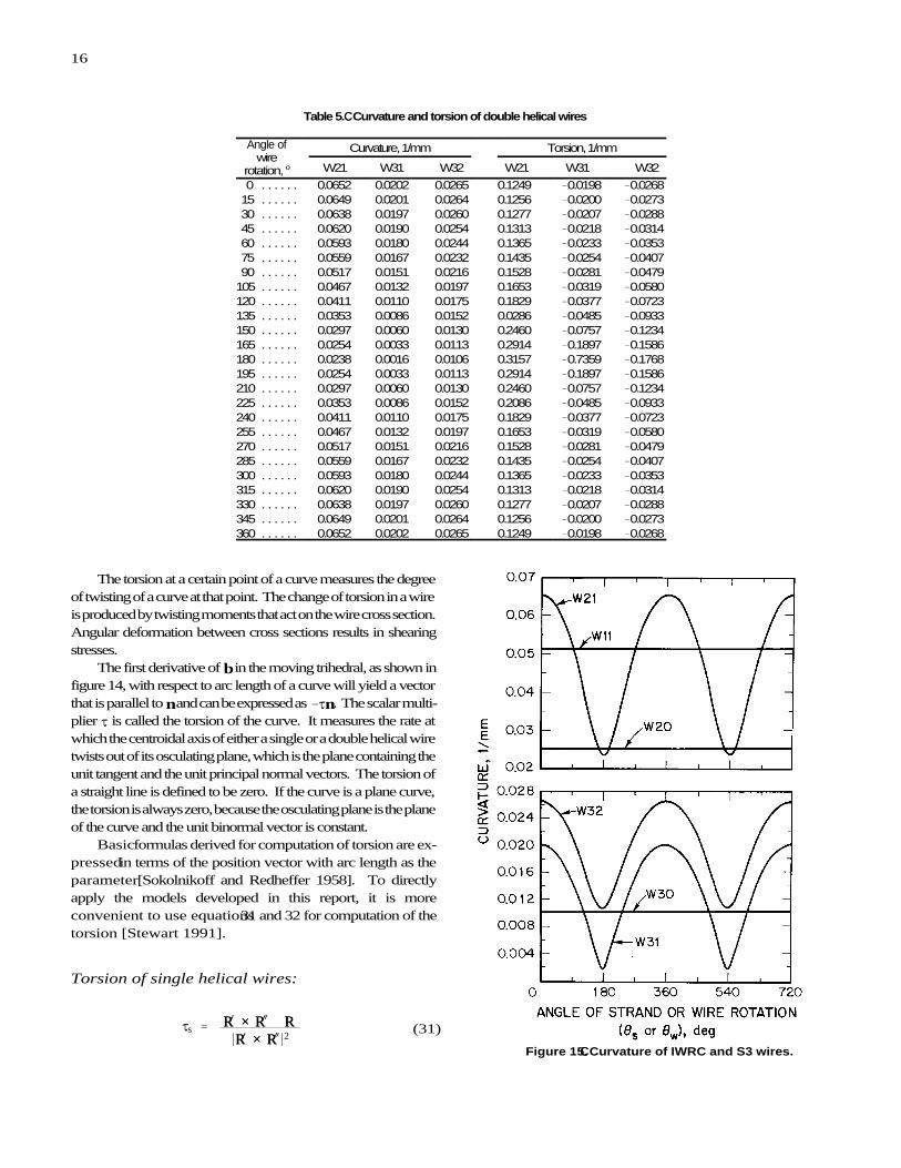
The curvatures of the IWRC and S3 helical wires were plottedagainst the absolute value of the angle of strand or wire rotation.Their relationships are shown in figure 15 for two periods. Theyindicate that (1) the curvature of single helical wires is independentof the angle of strand rotation, as expressed by equation 29b,(2) the curvature of double helical wires is a periodical function ofthe angle of wire rotation with a period of 360°, and (3) thecurvature of double helical wires is at maximum when the wiresare farthest from the rope center and at minimum when the wiresare nearest to the rope center because the angle of wire rotation ismeasured from the positive U-axis, which points away from therope center, as shown in figure 5.
Table 4.CCCurvature and torsionof single helical wires
WireCurvature,
1/mmTorsion,1/mm
W11 . . . . . . 0.0513 0.1753W20 . . . . . . 0.0252 0.0724W30 . . . . . . 0.0100 0.0179
16
Js ' RR! ×× RR" @@ RR“*RR! ×× RR"*2
(31)
Figure 15.CCCurvature of IWRC and S3 wires.
Table 5.CCCurvature and torsion of double helical wires
Angle ofwire
rotation, o
Curvature, 1/mm Torsion, 1/mm
W21 W31 W32 W21 W31 W32
0 . . . . . . 0.0652 0.0202 0.0265 0.1249 &0.0198 &0.0268 15 . . . . . . 0.0649 0.0201 0.0264 0.1256 &0.0200 &0.0273 30 . . . . . . 0.0638 0.0197 0.0260 0.1277 &0.0207 &0.0288 45 . . . . . . 0.0620 0.0190 0.0254 0.1313 &0.0218 &0.0314 60 . . . . . . 0.0593 0.0180 0.0244 0.1365 &0.0233 &0.0353 75 . . . . . . 0.0559 0.0167 0.0232 0.1435 &0.0254 &0.0407 90 . . . . . . 0.0517 0.0151 0.0216 0.1528 &0.0281 &0.0479105 . . . . . . 0.0467 0.0132 0.0197 0.1653 &0.0319 &0.0580120 . . . . . . 0.0411 0.0110 0.0175 0.1829 &0.0377 &0.0723135 . . . . . . 0.0353 0.0086 0.0152 0.0286 &0.0485 &0.0933150 . . . . . . 0.0297 0.0060 0.0130 0.2460 &0.0757 &0.1234165 . . . . . . 0.0254 0.0033 0.0113 0.2914 &0.1897 &0.1586180 . . . . . . 0.0238 0.0016 0.0106 0.3157 &0.7359 &0.1768195 . . . . . . 0.0254 0.0033 0.0113 0.2914 &0.1897 &0.1586210 . . . . . . 0.0297 0.0060 0.0130 0.2460 &0.0757 &0.1234225 . . . . . . 0.0353 0.0086 0.0152 0.2086 &0.0485 &0.0933240 . . . . . . 0.0411 0.0110 0.0175 0.1829 &0.0377 &0.0723255 . . . . . . 0.0467 0.0132 0.0197 0.1653 &0.0319 &0.0580270 . . . . . . 0.0517 0.0151 0.0216 0.1528 &0.0281 &0.0479285 . . . . . . 0.0559 0.0167 0.0232 0.1435 &0.0254 &0.0407300 . . . . . . 0.0593 0.0180 0.0244 0.1365 &0.0233 &0.0353315 . . . . . . 0.0620 0.0190 0.0254 0.1313 &0.0218 &0.0314330 . . . . . . 0.0638 0.0197 0.0260 0.1277 &0.0207 &0.0288345 . . . . . . 0.0649 0.0201 0.0264 0.1256 &0.0200 &0.0273360 . . . . . . 0.0652 0.0202 0.0265 0.1249 &0.0198 &0.0268
The torsion at a certain point of a curve measures the degreeof twisting of a curve at that point. The change of torsion in a wireis produced by twisting moments that act on the wire cross section.Angular deformation between cross sections results in shearingstresses.
The first derivative of b in the moving trihedral, as shown infigure 14, with respect to arc length of a curve will yield a vectorthat is parallel to n and can be expressed as &Jn. The scalar multi-plier J is called the torsion of the curve. It measures the rate atwhich the centroidal axis of either a single or a double helical wiretwists out of its osculating plane, which is the plane containing theunit tangent and the unit principal normal vectors. The torsion ofa straight line is defined to be zero. If the curve is a plane curve,the torsion is always zero, because the osculating plane is the planeof the curve and the unit binormal vector is constant.
Basic formulas derived for computation of torsion are ex-pressed in terms of the position vector with arc length as theparameter [Sokolnikoff and Redheffer 1958]. To directlyapply the models developed in this report, it is moreconvenient to use equations 31 and 32 for computation of thetorsion [Stewart 1991].
Torsion of single helical wires:

17
Jw 'P! × P" @@ P“
*P! × P"*2 (32)
Js 'xs“(ys!zs"& zs!ys") % ys“(zs!xs"& xs!zs") % zs“(xs!ys"& ys!xs")
(ys!zs"& zs!ys")2 % (zs!xs"& xs!zs")
2 % (xs!ys"& ys!xs")2 (31a)
Js 'sin("s) cos("s)
rs
(31b)
Jw 'xw“(yw!zw"& zw!yw") % yw“(zw!xw"& xw!zw") % zw“(xw!yw"& yw!xw")
(yw!zw"&zw!yw")2 % (zw!xw"& xw!zw")
2 % (xw!yw"& yw!xw")2 (32a)
Figure 16.CCTorsion of IWRC and S3 wires.
Torsion of double helical wires:
Substituting the derivatives of each vector into theequations and performing the cross and dot products and otheroperations, the expanded forms of these equations expressed interms of the component functions are shown below.
Expanded torsion equation for single helical wires:
After substituting the functions into equation 31a, it canbe reduced to its simplest form, as shown in equation 31b. Itindicates that the torsion of a single helical wire is independentof the angle of strand rotation and is constant for a given helixangle.
Expanded torsion equation for double helical wires:
The torsions of both single and double helical wires in a6×19 Seale wire rope were computed. The results for singlehelical wires are shown in table 4. The results for doublehelical wires are shown in table 5, with the absolute value of
2w increasing from 0° to 360° at increments of 15°. Thenegative torsions for W31 and W32 represent the twisting ofthe centroidal axes of these wires in a left lay strand, where thetwisting is opposite in direction to that in a right lay strand.
The torsions of the IWRC and S3 helical wires wereplotted against the absolute value of the angle of strand or wirerotation. Their relationships are shown in figure 16 for twoperiods. They indicate that (1) the torsion of single helicalwires is independent of the angle of strand rotation, asexpressed by equation 31b, (2) the torsion of double helicalwires is a periodical function of the angle of wire rotation witha period of 360°, and (3) the torsion of double helical wires isat minimum when the wires are farthest from the rope centerand at maximum when the wires are nearest to the rope center.It is also noted that the minimum torsion occurs at thelocations where the curvature is at maximum, and themaximum torsion occurs at the locations where the curvatureis at minimum.
ANALYSIS OF DEFORMATIONS
When a tensile load is applied to a wire rope, eachindividual wire will deform. Because of the differences in thewire lengths and the helix angles of single and double helicalwires, the load will not be distributed among the wires simplybased on the cross-sectional areas. The effect of these wire

18
Ssd ' [Ls(1% ,r)]2 % (2Br (33)
[Ls(1% ,r)]2 % (2Brsd)2 % (2 (34)
,s ' Ssd & Ss
Ss(35)
,w ' Swd & Sw
Sw(36)
deformations on the geometry of the rope structure needs to bedetermined. The major change is axial elongation along thecentroidal axis of a wire. Accompanying the axial elongationis a lateral contraction of the cross section. In addition,bending and twisting moments are generated in the wire thatcause changes in the curvature and torsion of the wire. Thecombination of all of these individual wire deformationsresults in the deformation of the rope structure.
There will be a resultant twisting moment, which willcause the rope to rotate if the ends are not restrained.Therefore, deformation of the rope structure will depend onwhether the rope is allowed to rotate or not. In mine hoisting,the cage or skip and rope are prevented from rotating by theshaft guides. Some rope manufacturers also produce rotation-resistant rope [Wire Rope Technical Board 1993], which ismade with layers of strands laid in opposite directions toproduce counteracting torques. In the use of rope with bothends restrained, the total number of strand lays and the totalnumber of wire lays in a rope are kept constant. Thus, therelative rotation, n, included in the models for double helicalwires, remains constant as the rope structure deforms underload. Because of the objective of evaluating the retirementcriteria for mine hoists, only the restrained-rotation case willbe considered in this report.
Axial Elongation and Lateral Contraction
The axial elongation and lateral contraction of the wireswill occur simultaneously when the rope is under tension.Neither can be determined independently. However, a suffi-cient number of equations may be established to obtain thesolutions for a given rope strain. The structural parameters ofthe deformed rope used in deriving the required equations arethe path length of the wire in each lay of the deformed strand,the wire strain, the reduced wire radius, and the radius of thedeformed helix. Each of them is described below. Thesymbols used are the same as those defined previously, exceptthat the subscript "d" has been added to represent their valuesin the deformed rope structure. The variable used to specifythe axial elongation of the rope is the rope strain, which isrepresented by ,r in the equations. It is determined by dividingthe amount of elongation of the rope by the original lengthbefore the application of load.
Wire Strain
Hooke's law states that, within the elastic range, thedeformation produced by external forces that act on nonrigidbodies is proportional to the stress. The path lengths of thewire before and after the application of load, therefore, areneeded to specify the axial deformation and determine thetensile stress.
To establish the relationship between the lengths of wireand rope in the deformed rope structure, the developed views,
which are the same as those shown in figure 3 for theundeformed rope, will be used. The only difference is toreplace the original structural parameters with thedeformed ones, i.e., Sr with Srd, Ss with Ssd, rs with rsd, "s
with "sd, Sw with Swd, rw with rwd, and "w with "wd. When 2s
' 2B, Srd becomes the deformed lay length of strand,which may be expressed as Ls(1 % ,r). On the basis of asingle lay of a strand, equations 33 and 34 are obtained forsingle and double helical wires, respectively. In each lay ofthe strand, a double helical wire has an angle of wirerotation of 2Bn, although the strand only has an angle ofstrand rotation of 2B.
Path length of the deformed single helical wire in each layof strand:
Path length of the deformed double helical wire in each layof strand:
The wire strain is the change of the path length of a wire,as expressed by equations 35 and 36.
Wire strain for single helical wires:
Wire strain for double helical wires:
Reduced Wire Radius
Experiments show that the axial elongation of a wire intension is always accompanied by lateral contraction of the wire.For any material, the ratio of the unit lateral contraction to the unitaxial elongation is known as Poisson's ratio, F, which is constantwithin the elastic range. The unit lateral contraction for a roundwire is determined by dividing the reduction of the wire radius inthe deformed rope structure by the original radius. If Rs and Rw
represent the original wire radii of single and double helical wires,respectively, the reduced wire radii, Rsd and Rwd, can be expressedin terms of the wire strain ,s and ,w, respectively, in accordancewith the definition of Poisson's ratio.

19

20
r32d & R 232d &
[uc L32(1%,30)]2
[L32(1%,30)]2 % (2Br32d)2
'&(c2uc % c5) % (c2 uc % c5)
2 & 4c3(c1 u 2c % c4 uc % c6)
2c3
(44)
Reduced radius of single helical wires:
Rsd ' Rs(1 & F,s) (37)
Reduced radius of double helical wires:
Rwd ' Rw(1 & F,w) (38)
A Poisson's ratio of 0.303 for steel [Avallone and Baumeister1986] may be used for determining the reduced wire radius atdifferent wire strains.
Radius of Deformed Helix
The radius of the deformed helix for single helical wiresis a function of the various reduced wire radii. For example,the radii of the deformed helices for wires W11 and W20,according to figures 6 through 8, are simply the sum of thevarious reduced wire radii, as shown below.
Radius of the deformed strand helix for wire W11:
r11d ' R10d % R11d (39)
Radius of the deformed strand helix for wire W20 or strand S2:
r20d ' R10d % 2R11d % 2R21d % R20d (40)
The radius of the deformed strand helix for wire W30 or strandS3 cannot be simply expressed as in equations 39 and 40 forwires W11 and W20. It will depend on the radius of thedeformed wire helix for wire W32, r32d, which is not merelythe sum of the various reduced wire radii. However, both canberelated by the following equation.
Radius of the deformed strand helix for wire W30 or strand S3:
r30d ' R10d % 2R11d % 4R21d % 2R20d % R32d % r32d (41)
The radius of the deformed wire helix for double helicalwires also is a function of the various reduced wire radii. Forexample, the radii of the deformed wire helix for wires W21and W31, according to figures 8 and 9, are simply the sum ofthe various reduced wire radii, as shown below.
Radius of the deformed wire helix for wire W21:
r21d ' R20d % R21d (42)
Radius of the deformed wire helix for wire W31:
r31d ' R30d % R31d (43)
The radius r32d will be dependent on the location of the contactpoint, as shown in figure 9, of the adjacent elliptical crosssections of wires W31 and W32 in the deformed rope structure.Assuming that the contact point between the wire W32 at 2w '&3B/2 rad and the wire W31 at 2w ' &(3B/2 % B/9) rad is at(uc,vc) on the U-V plane, which is perpendicular to thecentroidal axis of the deformed strand S3, equations 44 and 45can be derived. Equation 44 is obtained from the equations ofthe two ellipses by letting v31 of the upper quadrants be equalto v32 of the lower quadrants at u ' uc. Equation 45 is obtainedby letting their respective derivatives be equal, i.e., dv31/du 'dv32/du at u ' uc. The equations represent two conditions thatr32d must satisfy.
Radius of the deformed wire helix for wire W32 subject to twoconditions:

21
uc[L32 (1%,30 )]2
[L32 (1%,30 )]2% (2Br32d)2
[L32(1%,30)]2% (2Br32d)2
(R 232d&u 2
c )[L32 (1%,30 )]2% (2Br32d R32d)2
'1
2c3
&c2%c2(c2uc%c5)&2c3(2c1uc% c4)
(c2uc%c5)2& 4c3(c1u
2c % c4uc % c6)
(45)

22
c1 ' cos2(N) % sin2(N)c7
(46)
2sin(N)cos(N) % 2sin(N)c7
(47)
c3 ' sin2(N) % cos2(N)c7
(48)
4 ' &2sin(N)(R30d % R31d)c7
(49)
5 ' &2cos(N)(R30d % R31d)c7
(50)
[L30(1% ,r)]2 % (2Br30L30(1% ,r)]2 % (2Br30d)2 %
(52)
c6 '(R30d % R31d)
2 & R231d
c7(51)
"sd ' tan&1 Ls(1% ,r)2Brsd
(53)
"sd ' B & tan&1 Ls(1% ,r)2Brsd
(54)
wd' tan&1 [Ls(1% ,r)]2%(2Brsd)
(2Bnrwd)2(55)
wd' B& tan&1 [Ls(1% ,r)]2%(2Brsd(2Bnrwd)2
(56)
The coefficients c1 through c6 in these equations are describedby the following expressions, where N ' B/9. The commonterm in all of the coefficients is c7, as defined in equation 52.
Because wire W10 is the straight wire of strand S1, thewire strain is identical to the rope strain. Its reduced wireradius, R10d, is simply equivalent to R10(1 & F,r). The struc-tural parameters in length measurement for the other helicalwires are interrelated, as indicated by the equations above.They can be determined by solving the required simultaneousequations for the wires in each strand. For example, foursimultaneous equations, i.e., equations 33, 35, 37, and 39, maybe solved for the structural parameters of wire W11 under acertain rope strain. Once the structural parameters of the wiresin strand S1 in the deformed rope become known, thestructural parameters of the wires in strand S2 under the samerope strain can be determined by solving eight simultaneousequations, i.e., equations 33, 35, and 37 written for wire W20with equation 40 and equations 34, 36, and 38 written for wireW21 with equation 42. Using the solutions obtained for thewires in strands S1 and S2, the structural parameters of thewires in strand S3 under the same rope strain can bedetermined by solving 20 simultaneous equations, i.e.,equations 33, 35, and 37 written for wire W30 withequation 41; equations 34, 36, and 38 written for wire W31with equation 43; and equations 34, 36, and 38 written for wireW32 with equations 44 through 52.
Angle of Deformed Helix
When the rope elongates under tensile load and is re-strained from rotating, the angles of the strand and wire heliceswill also change because of the axial elongation and lateralcontraction of the wire. Using figure 3, the relationship be-tween the angle of the deformed strand or wire helix and therope strain, ,r, is given in the following equations.
Angle of the deformed strand helix:
If the original "s is less than B/2 rad, then
If the original "s is greater than B/2 rad, then
Angle of the deformed wire helix:
If the original "w is less than B/2 rad, then
If the original "w is greater than B/2 rad, then
Using the radii of the deformed helix determined previous-ly, the angle of the deformed helix for single helical wires, "sd,can be calculated with either equation 53 or 54, depending onwhether the original angle, "s, is less than or greater than B/2.Similarly, the angle of the deformed helix for double helicalwires, "wd, can be calculated with either equation 55 or 56, alsodepending on whether the original angle, "w, is less than orgreater than B/2. The lay length of strand, Ls, in these equa-tions is the original lay length.
The model for the deformed wire rope can now be con-structed by replacing the structural parameters in the originalmodel with the deformed ones obtained from the analysis ofdeformations shown above.

23
Bending and Twisting
To determine the bending and twisting of the wires, thecurvature and torsion of the deformed wires must be evaluated.The equations required for evaluation are the same as thosederived earlier, except that the structural parameters of the de-formed rope or the component functions of the deformedmodel must now be used in equations 29b and 31b for singlehelical wires and equations 30a and 32a for double helicalwires.
If 6sd and 6 wd represent the curvatures of the deformedsingle and double helical wires, respectively, then bendingmay be expressed as (6sd & 6s) or (6wd & 6w). Similarly, if Jsd
and Jwd
represent the torsions of the deformed single and doublehelical wires, respectively, then twisting may be expressed as(Jsd & Js) or (Jwd & Jw). As indicated by equations 29b and 31b,both the curvature and torsion of the deformed single helicalwires also will be independent of the angle of strand rotation.Therefore, both the bending and twisting of single helical wireswould be uniform along their entire paths when a load isapplied. Both the curvature and torsion of the deformeddouble helical wires are periodical functions of the angle ofwire rotation. The period is 2B, just as shown in figures 15and 16 for the undeformed double helical wires.
CONCLUSIONS
The model developed in this report fully describes the ge-ometry of the structure of wire ropes of any round-strandconstruction. It is expressed by vector equations in a three-dimensional, right-handed, rectangular Cartesian coordinatesystem and is general enough that any combination of wire andstrand lay directions can be handled if the stated sign conven-tions for the angles of strand and wire rotation and the relativerotation are followed in the component functions.
The wire paths are defined for the first time by using adeveloped model, which not only reveal the shapes of thevarious wires, but also are useful for predicting damagepatterns through external and internal wear. The geometricproperties of each wire can be easily evaluated by using thismodel. A 33-mm 6×19 Seale, IWRC, right regular lay wirerope was analyzed to illustrate the model's usefulness.
A system of equations was also established fordetermining the structural parameters of the deformed rope ata given rope strain, with restrained ends, thus obtaining themodel for the deformed rope. The geometric properties ofeach deformed wire can be evaluated the same way as shownin this report for the undeformed rope.
It is recommended for future work that stress analysis beconducted based on the changes of these geometric propertiesof the deformed wires to determine how the load is distributedamong these wires. Furthermore, the model could be used tostudy the effect of wear and breaking of wires on strength lossfor the various round-strand wire ropes used in mine hoistingso that more scientifically based retirement criteria can beestablished.
REFERENCES
Avallone EA, Baumeister T III, eds. [1986]. Marks' standard handbookfor mechanical engineers. 9th ed. New York, NY: McGraw-Hill Book Co.,p. 5-16.
CFR. Code of Federal regulations. Washington, DC: U.S. GovernmentPrinting Office, Office of the Federal Register.
Costello GA [1990]. Theory of wire rope. New York, NY: Springer-Verlag, pp. 53-54.
Lee WK [1991]. An insight into wire rope geometry. Int J SolidsStructures 28(4):471-490.
Leithold L [1986]. The calculus with analytic geometry. 5th ed. NewYork, NY: Harper & Row, Publishers, Inc., pp. 1072-1077.
Sokolnikoff IS, Redheffer RM [1958]. Mathematics of physics and modernengineering. New York, NY: McGraw-Hill Book Co., Inc., pp. 311-315.
Stewart J [1991]. Calculus. 2nd ed. Pacific Grove, CA: Brooks/ColePublishing Co., pp. 688-691.
Wire Rope Technical Board [1993]. Wire rope users manual. 3rd ed.Woodstock, MD: Wire Rope Technical Board.

DHHS (NIOSH) Publication No. 98-148
September 1998
To receive other information about occupational safety and health problems, call1-800-35-NIOSH (1-800-356-4674), or
visit the NIOSH Home Page on the World Wide Web at http://www.cdc.gov/niosh