model g4003g 12 x 36 gunsmith’s lathe w/standcdn2.grizzly.com/manuals/g4003g_m.pdfmodel g4003g...
TRANSCRIPT

MODEL G4003G12" X 36" GUNSMITH’S LATHE
w/STANDOWNER'S MANUAL
(For models manufactured since 1/15)
COPYRIGHT © MAY, 2007 BY GRIZZLY INDUSTRIAL, INC., REVISED MARCH, 2017 (BL)WARNING: NO PORTION OF THIS MANUAL MAY BE REPRODUCED IN ANY SHAPE
OR FORM WITHOUT THE WRITTEN APPROVAL OF GRIZZLY INDUSTRIAL, INC.#CRTRTSMN9327 PRINTED IN CHINA V3.03.17

This manual provides critical safety instructions on the proper setup, operation, maintenance, and service of this machine/tool. Save this document, refer to it often, and use it to instruct other operators.
Failure to read, understand and follow the instructions in this manual may result in fire or serious personal injury—including amputation, electrocution, or death.
The owner of this machine/tool is solely responsible for its safe use. This responsibility includes but is not limited to proper installation in a safe environment, personnel training and usage authorization, proper inspection and maintenance, manual availability and compre-hension, application of safety devices, cutting/sanding/grinding tool integrity, and the usage of personal protective equipment.
The manufacturer will not be held liable for injury or property damage from negligence, improper training, machine modifications or misuse.
Some dust created by power sanding, sawing, grinding, drilling, and other construction activities contains chemicals known to the State of California to cause cancer, birth defects or other reproductive harm. Some examples of these chemicals are:
• Lead from lead-based paints.• Crystalline silica from bricks, cement and other masonry products.• Arsenic and chromium from chemically-treated lumber.
Your risk from these exposures varies, depending on how often you do this type of work. To reduce your exposure to these chemicals: Work in a well ventilated area, and work with approved safety equip-ment, such as those dust masks that are specially designed to filter out microscopic particles.

Table of ContentsINTRODUCTION ............................................... 2
Machine Description ...................................... 2Contact Info.................................................... 2Manual Accuracy ........................................... 2Identification ................................................... 3Basic Controls ................................................ 4Machine Data Sheet ...................................... 6
SECTION 1: SAFETY ....................................... 9Safety Instructions for Machinery .................. 9Additional Safety for Metal Lathes ............... 11Additional Chuck Safety ............................... 12
SECTION 2: POWER SUPPLY ...................... 13
SECTION 3: SETUP ....................................... 15Preparation .................................................. 15Unpacking .................................................... 15Needed for Setup ......................................... 15Inventory ...................................................... 16Cleanup ........................................................ 17Site Considerations ...................................... 18Assembly ..................................................... 19Leveling ........................................................ 22Anchoring to Floor ....................................... 22Lubricating Lathe ......................................... 23Power Connection........................................ 23Test Run ...................................................... 25Spindle Break-In .......................................... 27Recommended Adjustments ........................ 27
SECTION 4: OPERATIONS ........................... 28Operation Overview ..................................... 28Chuck & Faceplate Mounting....................... 29Installation & Removal Devices ................... 29Chuck Installation......................................... 30Chuck Removal............................................ 31Scroll Chuck Clamping ................................ 32Chuck Jaw Reversal .................................... 324-Jaw Chuck ................................................ 33Faceplate ..................................................... 34Tailstock ....................................................... 35Centers ........................................................ 39Joining Drill Chuck & Arbor .......................... 41Steady Rest ................................................. 42Follow Rest .................................................. 43Carriage & Slide Locks ................................ 43Compound Rest ........................................... 44Tool Post ...................................................... 44Spider ........................................................... 46Manual Feed ................................................ 46
Spindle Speed.............................................. 47Power Feed.................................................. 48End Gears .................................................... 51Threading ..................................................... 52
SECTION 5: ACCESSORIES ......................... 55
SECTION 6: MAINTENANCE ......................... 60Schedule ...................................................... 60Cleaning/Protecting ...................................... 60Lubrication ................................................... 61Machine Storage .......................................... 66
SECTION 7: SERVICE ................................... 67Troubleshooting ........................................... 67Backlash Adjustment ................................... 70Gib Adjustment ............................................ 71Half Nut Adjustment ..................................... 73V-Belt Tension & Replacement.................... 73Gap Removal & Installation ......................... 74Spindle Bearing Preload .............................. 75
SECTION 8: WIRING ...................................... 79Wiring Safety Instructions ............................ 79Electrical Cabinet Wiring Diagram ............... 80Motor & Control Panel Wiring Diagrams ...... 82Other Component Wiring Diagrams............. 84
SECTION 9: PARTS ....................................... 86Accessories .................................................. 86Headstock Gearing ...................................... 87Headstock Controls...................................... 89Quick-Change Gearbox ............................... 91Apron ........................................................... 93Saddle & Cross Slide ................................... 95Compound Rest & Tool Holder .................... 96Tailstock ....................................................... 98Bed & Motor ................................................. 99Stand .......................................................... 100Feed Rod ................................................... 101Machine Labels .......................................... 102Electrical Components ............................... 103Steady Rest ............................................... 104Follow Rest ................................................ 104
SECTION 10: APPENDIX ............................. 105Feed Chart ................................................. 105Thread Dial Chart ...................................... 105Metric Threading Chart .............................. 105Inch Threading Chart ................................. 105
WARRANTY & RETURNS ........................... 109

-2- Model G4003G (Mfd. Since 1/15)
INTRODUCTION
Machine Description
We are proud to provide a high-quality owner’s manual with your new machine!
We made every effort to be exact with the instruc-tions, specifications, drawings, and photographs in this manual. Sometimes we make mistakes, but our policy of continuous improvement also means that sometimes the machine you receive is slightly different than shown in the manual.
If you find this to be the case, and the difference between the manual and machine leaves you confused or unsure about something, check our website for an updated version. We post current manuals and manual updates for free on our web-site at www.grizzly.com.
Alternatively, you can call our Technical Support for help. Before calling, make sure you write down the Manufacture Date and Serial Number from the machine ID label (see below). This information is required for us to provide proper tech support, and it helps us determine if updated documenta-tion is available for your machine.
Manufacture Date
Serial Number
Manual Accuracy
We stand behind our machines! If you have ques-tions or need help, contact us with the information below. Before contacting, make sure you get the serial number and manufacture date from the machine ID label. This will help us help you faster.
Grizzly Technical Support1815 W. Battlefield
Springfield, MO 65807Phone: (570) 546-9663
Email: [email protected]
We want your feedback on this manual. What did you like about it? Where could it be improved? Please take a few minutes to give us feedback.
Grizzly Documentation ManagerP.O. Box 2069
Bellingham, WA 98227-2069Email: [email protected]
Contact Info
To reduce your risk of serious injury, read this entire manual BEFORE using machine.
The Model G4003G 12" x 36" Gunsmith’s Lathe allows you to turn and chamber gun barrels. The included outboard spindle “spider” support and tailstock with 1⁄2" square-drive lock-down allow for precise alignment of centers—specifically for professional gunsmiths.
This lathe is packed with high-end features and all the essential accessories you need to get started.
Model G4003G (Mfd. Since 1/15) -3-
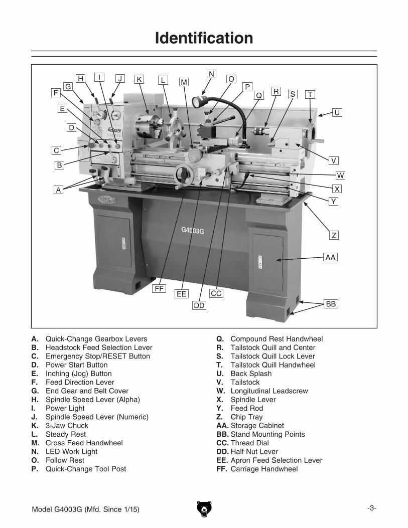
Identification
A. Quick-Change Gearbox LeversB. Headstock Feed Selection LeverC. Emergency Stop/RESET ButtonD. Power Start ButtonE. Inching (Jog) ButtonF. Feed Direction LeverG. End Gear and Belt CoverH. Spindle Speed Lever (Alpha)I. Power LightJ. Spindle Speed Lever (Numeric)K. 3-Jaw ChuckL. Steady RestM. Cross Feed HandwheelN. LED Work LightO. Follow RestP. Quick-Change Tool Post
Q. Compound Rest HandwheelR. Tailstock Quill and CenterS. Tailstock Quill Lock LeverT. Tailstock Quill HandwheelU. Back SplashV. TailstockW. Longitudinal LeadscrewX. Spindle LeverY. Feed RodZ. Chip TrayAA. Storage CabinetBB. Stand Mounting PointsCC. Thread DialDD. Half Nut LeverEE. Apron Feed Selection LeverFF. Carriage Handwheel
D
E
FG
H I J K L MN
OP
Q R S T
U
V
W
X
Y
Z
A
B
C
AA
CC
DD
EEFF
BB

-4- Model G4003G (Mfd. Since 1/15)
Basic Controls
Refer to Figures 1–4 and the following descrip-tions to learn the basic controls of the lathe. This information is necessary to successfully complete the SETUP section.
Headstock & Quick-Change Gearbox
A. Spindle Speed Levers: Used to select one of the nine spindle speeds.
B. Feed Direction Lever: Controls rotation direction of leadscrew and feed rod.
C. Spindle Speed Chart: Shows how to arrange spindle speed levers for each of the nine spindle speeds.
D. Metric Threading Chart: Displays the nec-essary configuration of gearbox levers and end gears for metric threading options.
E. Emergency Stop/RESET Button: Stops all machine functions. Twist clockwise to reset.
F. POWER START Button: Enables power to spindle motor after the emergency stop but-ton is reset.
G. INCHING (Jog) Button: Rotates spindle as long as it is pressed.
H. POWER Lamp: Illuminates when lathe con-trols are receiving power (Emergency Stop/RESET button must be reset).
I. Headstock Feed Selection Lever: Selects leadscrew for threading operations or feed rod for power feed operations.
J. Quick-Change Gearbox Levers: Control the leadscrew and feed rod rotation speed for threading and power feed operations.
K. Inch Threading Chart: Displays the neces-sary configuration of gearbox levers and end gears for inch threading options.
Figure 1. Headstock and quick-change gearbox controls.
B
C
EF GD
K
I
H
A
J

Model G4003G (Mfd. Since 1/15) -5-
Tailstock
W. Quill Handwheel: Moves quill toward or away from spindle.
X. 1⁄2" Square-Drive Lock-Down: Can be used with a torque wrench for precise alignment of centers.
Y. Tailstock Offset Screw (1 of 2): Adjusts tailstock offset left or right from spindle cen-terline.
Z. Quill: Moves toward or away from spindle. Holds centers or tooling.
End Gears
Figure 4. End gears.
End Gears
Configuring the end gears will control the speed of the leadscrew for threading or the feed rod for power feed operations. The rotational speed of these components depends not only on the end gear configuration, but the spindle speed as well.
Figure 3. Tailstock controls.
V
W
U
YZ
X
L. Quick-Change Tool Holder: Slides on or off tool post to allow the operator to quickly load and unload tools.
M. Compound Rest Handwheel: Moves tool toward or away from workpiece at the preset angle of compound rest.
N. Carriage Lock: Secures carriage in place for greater rigidity.
O . Thread Dial: Indicates when to engage half nut during inch threading operations.
P. Spindle Lever: Starts, stops, and reverses direction of spindle rotation.
Q . Half Nut Lever: Engages/disengages half nut for threading operations.
R. Apron Feed Selection Lever: Selects car-riage or cross slide for power feed.
S. Carriage Handwheel: Moves carriage along bed.
T. Cross Slide Handwheel: Moves tooling toward or away from the workpiece.
U. Quill Lock Lever: Secures quill in position.
V. Tailstock Lock Lever: Secures tailstock in position along bedway.
Carriage
Figure 2. Carriage controls.
M
T
S
QR
N
P
O
L

-6- Model G4003G (Mfd. Since 1/15)
The information contained herein is deemed accurate as of 11/27/2017 and represents our most recent product specifications.Due to our ongoing improvement efforts, this information may not accurately describe items previously purchased. PAGE 1 OF 3Model G4003G
MACHINE DATASHEET
Customer Service #: (570) 546-9663 · To Order Call: (800) 523-4777 · Fax #: (800) 438-5901
MODEL G4003G 12" X 36" GUNSMITHING LATHE WITHSTAND
Product Dimensions:
Weight............................................................................................................................................................ 1213 lbs.Width (side-to-side) x Depth (front-to-back) x Height..................................................................... 61 x 26 x 54-1/2 in.Footprint (Length x Width)............................................................................................................... 57-1/2 x 14-1/2 in.
Shipping Dimensions:
Carton #1Type................................................................................................................................................ Wood CrateContent................................................................................................................................................. MachineWeight.................................................................................................................................................. 1022 lbs.Length x Width x Height............................................................................................................. 66 x 30 x 29 in.Must Ship Upright......................................................................................................................................... Yes
Carton #2Type........................................................................................................................................... Cardboard BoxContent............................................................................................................................................... Left StandWeight.................................................................................................................................................... 164 lbs.Length x Width x Height............................................................................................................. 30 x 14 x 15 in.Must Ship Upright.......................................................................................................................................... No
Carton #3Type........................................................................................................................................... Cardboard BoxContent............................................................................................................................................ Right StandWeight.................................................................................................................................................... 144 lbs.Length x Width x Height............................................................................................................. 31 x 12 x 15 in.Must Ship Upright.......................................................................................................................................... No
Electrical:
Power Requirement........................................................................................................... 220V, Single-Phase, 60 HzPrewired Voltage.................................................................................................................................................. 220VFull-Load Current Rating....................................................................................................................................... 8.5AMinimum Circuit Size.............................................................................................................................................. 15AConnection Type....................................................................................................................................... Cord & PlugPower Cord Included............................................................................................................................................... NoRecommended Power Cord............................................................................... “S”-Type, 3-Wire, 14 AWG, 300 VACPlug Included........................................................................................................................................................... NoRecommended Plug Type..................................................................................................................................... 6-15Switch Type............................................................................................ Control Panel w/Magnetic Switch Protection
Motors:Main
Horsepower................................................................................................................................................ 2 HPPhase............................................................................................................................................ Single-PhaseAmps........................................................................................................................................................... 8.5ASpeed................................................................................................................................................ 1725 RPMType................................................................................................................. TEFC Capacitor-Start InductionPower Transfer ...................................................................................................................... Twin V-Belt DriveBearings..................................................................................................... Shielded & Permanently Lubricated
Machine Data Sheet

Model G4003G (Mfd. Since 1/15) -7-
The information contained herein is deemed accurate as of 11/27/2017 and represents our most recent product specifications.Due to our ongoing improvement efforts, this information may not accurately describe items previously purchased. PAGE 2 OF 3Model G4003G
Main Specifications:
Operation Info
Swing Over Bed......................................................................................................................................... 12 in.Distance Between Centers........................................................................................................................ 36 in.Swing Over Cross Slide............................................................................................................................... 7 in.Swing Over Saddle.......................................................................................................................... 11-11/32 in.Swing Over Gap........................................................................................................................................ 17 in.Maximum Tool Bit Size............................................................................................................................. 5/8 in.Compound Travel.................................................................................................................................. 3-1/4 in.Carriage Travel.................................................................................................................................... 30-1/2 in.Cross Slide Travel................................................................................................................................. 6-1/4 in.
Headstock Info
Spindle Bore........................................................................................................................................... 1.57 in.Spindle Taper............................................................................................................................................ MT#5Number of Spindle Speeds............................................................................................................................... 9Spindle Speeds......................................................................................................................... 70 – 1400 RPMSpindle Type................................................................................................................................ D1-5 CamlockSpindle Bearings................................................................................................ High-Precision Tapered RollerSpindle Length........................................................................................................................................... 17 in.Spindle Length with 3-Jaw Chuck....................................................................................................... 21-3/4 in.Spindle Length with 4-Jaw Chuck....................................................................................................... 21-1/4 in.Spindle Length with Faceplate............................................................................................................ 18-1/2 in.
Tailstock Info
Tailstock Quill Travel................................................................................................................................... 4 in.Tailstock Taper.......................................................................................................................................... MT#3Tailstock Barrel Diameter..................................................................................................................... 1.563 in.
Threading Info
Number of Longitudinal Feeds....................................................................................................................... 40Range of Longitudinal Feeds........................................................................................ 0.0011 – 0.0310 in./rev.Number of Cross Feeds................................................................................................................................. 40Range of Cross Feeds................................................................................................... 0.0004 – 0.0105 in./revNumber of Inch Threads................................................................................................................................. 40Range of Inch Threads.................................................................................................................... 4 – 112 TPINumber of Metric Threads.............................................................................................................................. 29Range of Metric Threads............................................................................................................... 0.2 – 4.5 mm
Dimensions
Bed Width.............................................................................................................................................. 7-1/4 in.Carriage Leadscrew Diameter.............................................................................................................. 0.870 in.Leadscrew TPI........................................................................................................................................... 8 TPICarriage Leadscrew Length....................................................................................................................... 44 in.Steady Rest Capacity................................................................................................................ 3/16 – 1-1/2 in.Follow Rest Capacity....................................................................................................................... 1/4 – 3/4 in.Faceplate Size........................................................................................................................................... 10 in.Feed Rod Diameter.................................................................................................................................. 3/4 in.Floor to Center Height......................................................................................................................... 46-1/4 in.Height With Leveling Jacks................................................................................................................. 48-1/4 in.
Construction
Base..................................................................................................................................................... Cast IronHeadstock............................................................................................................................................ Cast IronEnd Gears...................................................................................................................... Flame Hardened SteelBed........................................................................................ Induction-Hardened, Precision-Ground Cast IronBody..................................................................................................................................................... Cast IronStand.................................................................................................................................................... Cast IronPaint Type/Finish...................................................................................................................................... Epoxy

-8- Model G4003G (Mfd. Since 1/15)
The information contained herein is deemed accurate as of 11/27/2017 and represents our most recent product specifications.Due to our ongoing improvement efforts, this information may not accurately describe items previously purchased. PAGE 3 OF 3Model G4003G
Fluid Capacities
Headstock Capacity.................................................................................................................................. 3.5 qt.Headstock Fluid Type................................................................ ISO 32 (eg. Grizzly T23963, Mobil DTE Light)Gearbox Capacity........................................................................................................................... 1 – 2 PumpsGearbox Fluid Type............................................................. ISO 68 (SB1365, Grizzly T23962, Mobil Vactra 2)Apron Capacity......................................................................................................................................... 0.5 qt.Apron Fluid Type.......................................................................... ISO 68 (eg. Grizzly T23962, Mobil Vactra 2)
Other Specifications:
Country of Origin ................................................................................................................................................ ChinaWarranty ........................................................................................................................................................... 1 YearApproximate Assembly & Setup Time ...................................................................................................... 1-1/2 HoursSerial Number Location ........................................................................................................... ID Label on HeadstockISO 9001 Factory .................................................................................................................................................... NoCertified by a Nationally Recognized Testing Laboratory (NRTL) .......................................................................... No
Features:
1/2" SQ. Drive in Tailstock for Using Torque Wrench to Lock Tailstock Down Precisely Every TimeMin. Gun Barrel Length Through Spindle w/4-Jaw Chuck - 23" (Allowing for Barrel Sticking Out for Threading)Removable Gap Bed Allows Turnings up to 17" in DiameterEasy to Use Lever ControlsFull Length Splash GuardOn/Off Reverse Switch on CarriageHalogen Work LightBall Bearing Steady/Follow RestsOutboard End Support ScrewsSocket for Tailstock LockSteel Stand with Extended BaseCast Aluminum Gear CoverV-Slide for Side Adjustment
Accessories Included:
1 MT#3 Live Center1/2" Chuck with MT#3 Arbor10" Face Plate2 MT#3 Dead Centers (1 Carbide Tipped)6" 3-Jaw Chuck with 2 Sets of Jaws8" 4-Jaw Chuck with Reversible JawsFollow Rest with Roller TipsQuick Change Tool Post with One Tool HolderSteady Rest with Roller TipsToolboxSet of Seven Change Gears

Model G4003G (Mfd. Since 1/15) -9-
ELECTRICAL EQUIPMENT INJURY RISKS. You can be shocked, burned, or killed by touching live electrical components or improperly grounded machinery. To reduce this risk, only allow qualified service personnel to do electrical installation or repair work, and always disconnect power before accessing or exposing electrical equipment.
DISCONNECT POWER FIRST. Always discon-nect machine from power supply BEFORE making adjustments, changing tooling, or servicing machine. This prevents an injury risk from unintended startup or contact with live electrical components.
EYE PROTECTION. Always wear ANSI-approved safety glasses or a face shield when operating or observing machinery to reduce the risk of eye injury or blindness from flying particles. Everyday eyeglasses are NOT approved safety glasses.
OWNER’S MANUAL. Read and understand this owner’s manual BEFORE using machine.
TRAINED OPERATORS ONLY. Untrained oper-ators have a higher risk of being hurt or killed. Only allow trained/supervised people to use this machine. When machine is not being used, dis-connect power, remove switch keys, or lock-out machine to prevent unauthorized use—especially around children. Make your workshop kid proof!
DANGEROUS ENVIRONMENTS. Do not use machinery in areas that are wet, cluttered, or have poor lighting. Operating machinery in these areas greatly increases the risk of accidents and injury.
MENTAL ALERTNESS REQUIRED. Full mental alertness is required for safe operation of machin-ery. Never operate under the influence of drugs or alcohol, when tired, or when distracted.
For Your Own Safety, Read Instruction Manual Before Operating This Machine
The purpose of safety symbols is to attract your attention to possible hazardous conditions. This manual uses a series of symbols and signal words intended to convey the level of impor-tance of the safety messages. The progression of symbols is described below. Remember that safety messages by themselves do not eliminate danger and are not a substitute for proper accident prevention measures. Always use common sense and good judgment.
Indicates a potentially hazardous situation which, if not avoided, MAY result in minor or moderate injury. It may also be used to alert against unsafe practices.
Indicates a potentially hazardous situation which, if not avoided, COULD result in death or serious injury.
Indicates an imminently hazardous situation which, if not avoided, WILL result in death or serious injury.
This symbol is used to alert the user to useful information about proper operation of the machine.NOTICE
Safety Instructions for Machinery
SECTION 1: SAFETY

-10- Model G4003G (Mfd. Since 1/15)
WEARING PROPER APPAREL. Do not wear clothing, apparel or jewelry that can become entangled in moving parts. Always tie back or cover long hair. Wear non-slip footwear to reduce risk of slipping and losing control or accidentally contacting cutting tool or moving parts.
HAZARDOUS DUST. Dust created by machinery operations may cause cancer, birth defects, or long-term respiratory damage. Be aware of dust hazards associated with each workpiece mate-rial. Always wear a NIOSH-approved respirator to reduce your risk.
HEARING PROTECTION. Always wear hear-ing protection when operating or observing loud machinery. Extended exposure to this noise without hearing protection can cause permanent hearing loss.
REMOVE ADJUSTING TOOLS. Tools left on machinery can become dangerous projectiles upon startup. Never leave chuck keys, wrenches, or any other tools on machine. Always verify removal before starting!
USE CORRECT TOOL FOR THE JOB. Only use this tool for its intended purpose—do not force it or an attachment to do a job for which it was not designed. Never make unapproved modifica-tions—modifying tool or using it differently than intended may result in malfunction or mechanical failure that can lead to personal injury or death!
AWKWARD POSITIONS. Keep proper footing and balance at all times when operating machine. Do not overreach! Avoid awkward hand positions that make workpiece control difficult or increase the risk of accidental injury.
CHILDREN & BYSTANDERS. Keep children and bystanders at a safe distance from the work area.Stop using machine if they become a distraction.
GUARDS & COVERS. Guards and covers reduce accidental contact with moving parts or flying debris. Make sure they are properly installed, undamaged, and working correctly BEFORE operating machine.
FORCING MACHINERY. Do not force machine. It will do the job safer and better at the rate for which it was designed.
NEVER STAND ON MACHINE. Serious injury may occur if machine is tipped or if the cutting tool is unintentionally contacted.
STABLE MACHINE. Unexpected movement dur-ing operation greatly increases risk of injury or loss of control. Before starting, verify machine is stable and mobile base (if used) is locked.
USE RECOMMENDED ACCESSORIES. Consult this owner’s manual or the manufacturer for rec-ommended accessories. Using improper acces-sories will increase the risk of serious injury.
UNATTENDED OPERATION. To reduce the risk of accidental injury, turn machine OFF and ensure all moving parts completely stop before walking away. Never leave machine running while unattended.
MAINTAIN WITH CARE. Follow all maintenance instructions and lubrication schedules to keep machine in good working condition. A machine that is improperly maintained could malfunction, leading to serious personal injury or death.
DAMAGED PARTS. Regularly inspect machine for damaged, loose, or mis-adjusted parts—or any condition that could affect safe operation. Immediately repair/replace BEFORE operating machine. For your own safety, DO NOT operate machine with damaged parts!
MAINTAIN POWER CORDS. When disconnect-ing cord-connected machines from power, grab and pull the plug—NOT the cord. Pulling the cord may damage the wires inside. Do not handle cord/plug with wet hands. Avoid cord damage by keeping it away from heated surfaces, high traffic areas, harsh chemicals, and wet/damp locations.
EXPERIENCING DIFFICULTIES. If at any time you experience difficulties performing the intend-ed operation, stop using the machine! Contact our Technical Support at (570) 546-9663.

Model G4003G (Mfd. Since 1/15) -11-
Additional Safety for Metal Lathes
CLOTHING, JEWELRY & LONG HAIR. Tie back long hair, remove jewelry, and do not wear loose clothing or gloves. These can easily get caught on rotating parts and pull you into lathe.
ROTATING PARTS. Always keep hands and body at a safe distance from rotating parts—especially those with projecting surfaces. Never hold any-thing against rotating workpiece, such as emery cloth, that can pull you into lathe.
GUARDING. Guards and covers protect against entanglement or flying objects. Always ensure they are properly installed while machine is running.
ADJUSTMENT TOOLS. Remove all chuck keys, wrenches, and adjustment tools before turning lathe ON. A tool left on the lathe can become a deadly projectile when spindle is started.
SAFE CLEARANCES. Before starting spindle, verify workpiece has adequate clearance by hand-rotating it through its entire range of motion.
NEW SETUPS. Test each new setup by starting spindle rotation at the lowest speed and standing to the side of the lathe until workpiece reaches full speed and you can verify safe rotation.
SPINDLE SPEEDS. Using spindle speeds that are too fast for the workpiece or clamping equipment can cause rotating parts to come loose and strike nearby people with deadly force. Always use slow spindle speeds with large or non-concentric work-pieces. Never exceed rated RPM of the chuck.
LONG STOCK SAFETY. Long stock can whip violently if not properly supported. Always support any stock that extends from the chuck/headstock more than three times its own diameter.
CLEARING CHIPS. Metal chips can be razor sharp. Avoid clearing them by hand or with a rag. Use a brush or vacuum instead.
SECURE WORKPIECE. An improperly secured workpiece can fly off spindle with deadly force. Make sure workpiece is properly secured before starting the lathe.
CHUCKS. Chucks can be heavy and difficult to hold. During installation and removal, protect your hands and precision bed ways by using a chuck cradle or piece of plywood over the bed ways. Use lifting equipment, as necessary, for large chucks.
STOPPING SPINDLE. Always allow spindle to completely stop on its own, or use a brake, if provided. Never put hands or another object on a spinning workpiece to make it stop faster.
CRASHING. A serious explosion of metal parts can occur if cutting tool or other lathe component hits rotating chuck or a projecting part of work-piece. Resulting metal fragments can strike nearby people and lathe will be seriously damaged. To reduce risk of crashing, ALWAYS release automat-ic feeds after use, NEVER leave lathe unattended, and CHECK all clearances before starting lathe.
COOLANT SAFETY. Coolant can become very toxic through prolonged use and aging. To mini-mize toxicity, change coolant regularly. When using, position nozzle properly to avoid splashing operator or causing a slipping hazard on floor.
TOOL SELECTION. Cutting with incorrect or dull tooling increases risk of injury from broken or dis-lodged components, or as a result of extra force required for operation. Always use sharp tooling that is right for the job.
SANDING/POLISHING. To reduce risk of entan-glement, never wrap emery cloth around rotating workpiece. Instead, use emery cloth with the aid of a tool or backing board.
MEASURING WORKPIECE. To reduce risk of entanglement, never measure rotating workpieces.
Serious injury or death can occur from getting entangled in, crushed between, or struck by rotating parts on a lathe! Unsecured tools or workpieces that fly loose from rotating objects can also strike nearby operators with deadly force. To minimize the risk of getting hurt or killed, anyone operating this machine MUST completely heed the hazards and warnings below.

-12- Model G4003G (Mfd. Since 1/15)
Additional Chuck Safety
ENTANGLEMENT. Entanglement with a rotat-ing chuck can lead to death, amputation, broken bones, or other serious injury. Never attempt to slow or stop the lathe chuck by hand, and always roll up long sleeves, tie back long hair, and remove any jewelry or loose apparel BEFORE operating.
CHUCK SPEED RATING. Excessive spindle speeds greatly increase the risk of the workpiece or chuck being thrown from the machine with deadly force. Never use spindle speeds faster than the chuck RPM rating or the safe limits of your workpiece.
USING CORRECT EQUIPMENT. Many workpiec-es can only be safely turned in a lathe if additional support equipment, such as a tailstock or steady/follow rest, is used. If the operation is too hazard-ous to be completed with the lathe or existing equipment, the operator must have enough experi-ence to know when to use a different machine or find a safer way.
TRAINED OPERATORS ONLY. Using a chuck incorrectly can result in workpieces coming loose at high speeds and striking the operator or bystand-ers with deadly force. To reduce the risk of this haz-ard, read and understand this document and seek additional training from an experienced chuck user before using a chuck.
CHUCK CAPACITY. Avoid exceeding the capacity of the chuck by clamping an oversized workpiece. If the workpiece is too large to safely clamp with the chuck, use a faceplate or a larger chuck if pos-sible. Otherwise, the workpiece could be thrown from the lathe during operation, resulting in serious impact injury or death.
CLAMPING FORCE. Inadequate clamping force can lead to the workpiece being thrown from the chuck and striking the operator or bystanders. Maximum clamping force is achieved when the chuck is properly maintained and lubricated, all jaws are fully engaged with the workpiece, and the maximum chuck clamping diameter is not exceeded.
PROPER MAINTENANCE. All chucks must be properly maintained and lubricated to achieve maximum clamping force and withstand the rigors of centrifugal force. To reduce the risk of a thrown workpiece, follow all maintenance intervals and instructions in this document.
DISCONNECT POWER. Serious entanglement or impact injuries could occur if the lathe is started while you are adjusting, servicing, or installing the chuck. Always disconnect the lathe from power before performing these procedures.

Model G4003G (Mfd. Since 1/15) -13-
SECTION 2: POWER SUPPLY
AvailabilityBefore installing the machine, consider the avail-ability and proximity of the required power supply circuit. If an existing circuit does not meet the requirements for this machine, a new circuit must be installed. To minimize the risk of electrocution, fire, or equipment damage, installation work and electrical wiring must be done by an electrician or qualified service personnel in accordance with all applicable codes and standards.
Electrocution, fire, shock, or equipment damage may occur if machine is not properly grounded and connected to power supply.
Full-Load Current RatingThe full-load current rating is the amperage a machine draws at 100% of the rated output power. On machines with multiple motors, this is the amperage drawn by the largest motor or sum of all motors and electrical devices that might operate at one time during normal operations.
Full-Load Current Rating at 220V .... 8.5 Amps
The full-load current is not the maximum amount of amps that the machine will draw. If the machine is overloaded, it will draw additional amps beyond the full-load rating.
If the machine is overloaded for a sufficient length of time, damage, overheating, or fire may result—especially if connected to an undersized circuit. To reduce the risk of these hazards, avoid over-loading the machine during operation and make sure it is connected to a power supply circuit that meets the specified circuit requirements.
Circuit Requirements for 220VThis machine is prewired to operate on a power supply circuit that has a verified ground and meets the following requirements:
Nominal Voltage .............................. 220V/240VCycle ..........................................................60 HzPhase .................................................... 1-PhasePower Supply Circuit ......................... 15 AmpsPlug/Receptacle ............................. NEMA 6-15Cord ........“S”-Type, 3-Wire, 14 AWG, 300 VAC
For your own safety and protection of property, consult an electrician if you are unsure about wiring practices or electrical codes in your area.
Note: Circuit requirements in this manual apply to a dedicated circuit—where only one machine will be running on the circuit at a time. If machine will be connected to a shared circuit where multiple machines may be running at the same time, con-sult an electrician or qualified service personnel to ensure circuit is properly sized for safe operation.
A power supply circuit includes all electrical equipment between the breaker box or fuse panel in the building and the machine. The power sup-ply circuit used for this machine must be sized to safely handle the full-load current drawn from the machine for an extended period of time. (If this machine is connected to a circuit protected by fuses, use a time delay fuse marked D.)

-14- Model G4003G (Mfd. Since 1/15)
Extension CordsWe do not recommend using an extension cord with this machine. If you must use an extension cord, only use it if absolutely necessary and only on a temporary basis.
Extension cords cause voltage drop, which can damage electrical components and shorten motor life. Voltage drop increases as the extension cord size gets longer and the gauge size gets smaller (higher gauge numbers indicate smaller sizes).
Any extension cord used with this machine must be in good condition and contain a ground wire and matching plug/receptacle. Additionally, it must meet the following size requirements:
Minimum Gauge Size ...........................14 AWGMaximum Length (Shorter is Better).......50 ft.
Grounding InstructionsThis machine MUST be grounded. In the event of certain malfunctions or breakdowns, grounding reduces the risk of electric shock by providing a path of least resistance for electric current.
Figure 5. Typical 6-15 plug and receptacle.
Grounding Prong
Current Carrying Prongs
6-15 PLUG
GROUNDED6-15 RECEPTACLE
Improper connection of the equipment-grounding wire can result in a risk of electric shock. The wire with green insulation (with or without yellow stripes) is the equipment-grounding wire. If repair or replacement of the power cord or plug is nec-essary, do not connect the equipment-grounding wire to a live (current carrying) terminal. Check with a qualified electrician or service per-sonnel if you do not understand these grounding requirements, or if you are in doubt about whether the tool is properly grounded. If you ever notice that a cord or plug is damaged or worn, discon-nect it from power, and immediately replace it with a new one.
The power cord and plug specified under “Circuit Requirements for 220V” on the previous page has an equipment-grounding wire and a ground-ing prong. The plug must only be inserted into a matching receptacle (outlet) that is properly installed and grounded in accordance with all local codes and ordinances (see figure below).
No adapter should be used with plug. If plug does not fit available receptacle, or if machine must be reconnected for use on a different type of circuit, reconnection must be performed by an electrician or qualified service personnel, and it must comply with all local codes and ordinances.
Serious injury could occur if you connect machine to power before completing setup process. DO NOT connect to power until instructed later in this manual.

Model G4003G (Mfd. Since 1/15) -15-
SECTION 3: SETUP
This machine was carefully packaged for safe transport. When unpacking, separate all enclosed items from packaging materials and inspect them for shipping damage. If items are damaged, please call us immediately at (570) 546-9663.
IMPORTANT: Save all packaging materials until you are completely satisfied with the machine and have resolved any issues between Grizzly or the shipping agent. You MUST have the original pack-aging to file a freight claim. It is also extremely helpful if you need to return your machine later.
Unpacking
The list below outlines the basic process of pre-paring your machine for operation. Specific steps are covered later in this section.
The typical preparation process is as follows:
1. Unpack the lathe and inventory the contents of the box/crate.
2. Clean the lathe and its components.
3. Identify an acceptable location for the lathe and move it to that location.
4. Mount the lathe on the stand and bolt it to the floor.
5. Assemble the loose components and make any necessary adjustments or inspections to ensure the lathe is ready for operation.
6. Check lathe for proper lubrication.
7. Connect the lathe to the power source.
8. Test run lathe to ensure it functions properly.
9. Perform the spindle break-in procedure to prepare the lathe for operation.
Preparation
The following are needed to complete the setup process, but are not included with your machine.
• For Lifting and Moving:— A forklift or other power lifting device rated
for at least 2000 lbs.— Two lifting straps rated for at least 2000
lbs. each — Lifting chain and safety hook rated for at
least 2000 lbs. each— Another person to guide machine
• For Power Connection:— A power source that meets the minimum cir-
cuit requirements for this machine (review Power Supply on Page 13 for details)
— An electrician or qualified service person-nel to ensure a safe and code-compliant connection to the power source
• For Assembly:— Shop rags— Cleaner/degreaser (see Page 17)— Quality metal protectant lubricant— Safety glasses for each person— Anchoring hardware as needed
(see Page 22) — Precision level at least 12" long— Silicone sealant
Needed for Setup
SUFFOCATION HAZARD!Keep children and pets away from plastic bags or packing materials shipped with this machine. Discard immediately.

-16- Model G4003G (Mfd. Since 1/15)
Inventory X. Drill Chuck B16 1.5-13mm .......................... 1Y. Drill Chuck Key ........................................... 1Z. Spider Bolts w/Nuts .................................... 4AA. Fasteners (Not Shown): —Hex Bolts M12-1.75 x 40 ......................... 6 —Flat Washers 12mm ................................ 6 —Phillips Head Screws M6-1 x 10 ........... 12 —Hex Nuts M6-1 ........................................ 4 —Flat Washers 6mm ............................... 12
Figure 7. Loose components.
H
F
IG
KJ
U
V
S TR
QPONM
L
WZ
X
Y
Figure 6. Major components.
E
The following is a list of items shipped with your machine. Before beginning setup, lay these items out and inventory them.
If any non-proprietary parts are missing (e.g. a nut or a washer), we will gladly replace them; or for the sake of expediency, replacements can be obtained at your local hardware store.
Major Components (Figure 6) Qty.A. 6" Three-Jaw Chuck w/Jaws ...................... 1B. Steady Rest ................................................ 1C. Follow Rest ................................................. 1D. Quick Change Tool Post............................. 1E. Stand: Cabinets (Left & Right) ............................... 2 Front Panel ................................................. 1 Front Panel Brackets .................................. 2
Loose Components (Figure 7)F. 8" Four-Jaw Universal Chuck w/Camlock Studs and Cap Screws ............ 1G. 10" Faceplate .............................................. 1H. Bottle for Oil ............................................... 1I. Tool Box...................................................... 1J. Tailstock Wrench ........................................ 1K. 3- and 4-Jaw Chuck Wrenches .............1 EaL. Square Socket T-Wrench ........................... 1M. Quick Change Tool Holder ......................... 1N. Change Gears ............................................ 1 —Gear 27-tooth .......................................... 1 —Gear 26-tooth ......................................... 1 —Gear 35-tooth ......................................... 1 —Gear 36-tooth ......................................... 1 —Gears 40-tooth (Installed) ....................... 2 —Gear 45-tooth ......................................... 1 —Gear 50-tooth ......................................... 1 —Gear 60-tooth ......................................... 1 —Gear 86/91-tooth (Installed) .................... 1O. Hex Wrench Set 2, 4, 5, 6, 8, 10 mm ....1 EaP. Wrenches 9/11, 10/12, 12/14 ..................1 EaQ. Handwheel Handles ................................... 2R. Spindle Sleeve MT#5 to MT#3 ................... 1 S. Arbor B16 to MT#3 ..................................... 1T. Standard Dead Center MT#3 ..................... 1U. Carbide Tipped Dead Center MT#3 ........... 1V. Live Center MT#3 ....................................... 1W. Phillips & Flat Screwdrivers #2 ..............1 Ea
NOTICEIf you cannot find an item on this list, care-fully check around/inside the machine and packaging materials. Often, these items get lost in packaging materials while unpack-ing or they are pre-installed at the factory.
DA CB

Model G4003G (Mfd. Since 1/15) -17-
The unpainted surfaces of your machine are coated with a heavy-duty rust preventative that prevents corrosion during shipment and storage. This rust preventative works extremely well, but it will take a little time to clean.
Be patient and do a thorough job cleaning your machine. The time you spend doing this now will give you a better appreciation for the proper care of your machine's unpainted surfaces.
There are many ways to remove this rust preven-tative, but the following steps work well in a wide variety of situations. Always follow the manufac-turer’s instructions with any cleaning product you use and make sure you work in a well-ventilated area to minimize exposure to toxic fumes.
Before cleaning, gather the following:• Disposable rags• Cleaner/degreaser (WD•40 works well)• Safety glasses & disposable gloves• Plastic paint scraper (optional)
Basic steps for removing rust preventative:
1. Put on safety glasses.
2. Coat the rust preventative with a liberal amount of cleaner/degreaser, then let it soak for 5–10 minutes.
3. Wipe off the surfaces. If your cleaner/degreas-er is effective, the rust preventative will wipe off easily. If you have a plastic paint scraper, scrape off as much as you can first, then wipe off the rest with the rag.
4. Repeat Steps 2–3 as necessary until clean, then coat all unpainted surfaces with a quality metal protectant to prevent rust.
Gasoline and petroleum products have low flash points and can explode or cause fire if used to clean machinery. Avoid using these products to clean machinery.
Many cleaning solvents are toxic if inhaled. Only work in a well-ventilated area.
NOTICEAvoid chlorine-based solvents, such as acetone or brake parts cleaner, that may damage painted surfaces.
T23692—Orange Power DegreaserA great product for removing the waxy shipping grease from your machine during clean up.
Figure 8. T23692 Orange Power Degreaser.
Cleanup

-18- Model G4003G (Mfd. Since 1/15)
Site Considerations
Figure 9. Minimum working clearances.
Keep Workpiece
Loading Area Unobstructed
Wall
30" MinimumClearance forMaintenance
671⁄2"
26"
Not to Scale
Weight LoadRefer to the Machine Data Sheet for the weight of your machine. Make sure that the surface upon which the machine is placed will bear the weight of the machine, additional equipment that may be installed on the machine, and the heaviest work-piece that will be used. Additionally, consider the weight of the operator and any dynamic loading that may occur when operating the machine.
Space AllocationConsider the largest size of workpiece that will be processed through this machine and provide enough space around the machine for adequate operator material handling or the installation of auxiliary equipment. With permanent installations, leave enough space around the machine to open or remove doors/covers as required by the main-tenance and service described in this manual. See below for required space allocation.
Physical EnvironmentThe physical environment where the machine is operated is important for safe operation and lon-gevity of machine components. For best results, operate this machine in a dry environment that is free from excessive moisture, hazardous chemi-cals, airborne abrasives, or extreme conditions. Extreme conditions for this type of machinery are generally those where the ambient temperature range exceeds 41°–104°F; the relative humidity range exceeds 20%–95% (non-condensing); or the environment is subject to vibration, shocks, or bumps.
Electrical InstallationPlace this machine near an existing power source. Make sure all power cords are protected from traffic, material handling, moisture, chemicals, or other hazards. Make sure to leave enough space around machine to disconnect power supply or apply a lockout/tagout device, if required.
LightingLighting around the machine must be adequate enough that operations can be performed safely. Shadows, glare, or strobe effects that may distract or impede the operator must be eliminated.
Children or untrained people may be seriously injured by this machine. Only install in an access restricted location.

Model G4003G (Mfd. Since 1/15) -19-
Assembly
HEAVY LIFT!Straining or crushing injury may occur from improperly lifting machine or some of its parts. To reduce this risk, get help from other people and use a forklift (or other lifting equipment) rated for weight of this machine.
Assembling the Model G4003G consists of build-ing the stand assembly, attaching the handwheel handles, placing and securing the lathe on the stand, anchoring the stand to the floor, and attaching the back splash.
To assemble the lathe:
1. Position left and right cabinets approximately 34" apart in prepared location.
2. Secure front panel brackets to cabinets with (4) M6-1 x 10 Phillips head screws and (4) 6mm flat washers (see Figure 10).
Figure 10. Brackets installed (rear view).
x 4
Brackets
Cabinets
3. Install front panel on panel brackets with (4) M6-1 x 10 Phillips head screws, (4) 6mm flat washers, and (4) M6-1 hex nuts (see Figure 11).
Figure 11. Front panel installed.
Front Panel
Recommended: Use the mounting holes (approximately 3⁄8" in diameter) in the cabi-nets (see Figure 12) to mark and drill holes in the floor, then anchor the stand assembly to the floor. Use shims to level the assembly as needed. Refer to Leveling on Page 22 and Anchoring to Floor on Page 22 for detailed information.
Figure 12. Locations of cabinet mounting holes(two on each cabinet).
MountingHoles
4. Remove crate from lathe shipping pallet, then remove all loose items.
IMPORTANT: Lifting and placing the lathe requires at least one other person for assis-tance and a forklift with two lifting straps, lift-ing chain, and a safety hook rated for at least 2000 lbs. each.

-20- Model G4003G (Mfd. Since 1/15)
5. Move lathe to its prepared location while it is still attached to the shipping pallet.
6. Unbolt lathe from the shipping pallet.
7. Attach handles to cross slide and carriage handwheels (see Figure 13).
Figure 13. Handwheel handles attached.
HandwheelHandles
8. To balance load for lifting, move tailstock and carriage to right end of bedway, then lock them in place.
Note: Before attempting to move the car-riage, make sure the carriage lock is loose, the half nut is disengaged, and the feed selection lever is disengaged. Refer to Basic Controls beginning on Page 4 to identify these components.
9. Wrap two lifting straps around right bedway pedestal and left bedway under chuck.
IMPORTANT: To avoid damaging preci-sion parts, route straps BEHIND control rod, feed rod, and lead screw, as illustrated in Figure 14. This will help prevent lifting straps from bending or damaging these parts during lifting.
10. Position chip pan on top of cabinet stand and align six mounting holes with those in cabi-nets.
11. Have another person hold onto the lathe to prevent it from swinging as you slowly raise lathe from pallet and move it over stand.
12. Apply a 1⁄4" bead of silicone around bottom edge of bedway pedestals.
Note: When the lathe is placed onto the chip pan the silicone will form a protective seal to help prevent fluid leaking into the cabinets.
13. Place lathe on stand while aligning mounting holes in lathe bed with holes in chip pan.
Chuck
Figure 14. Lifting straps properly fitted on the lathe.
Right Bedway Pedestal
Straps routed behind control rod, feed rod, and leadscrew

Model G4003G (Mfd. Since 1/15) -21-
14. Remove headstock end cover to gain better access to the headstock base pedestal (see Figure 15).
Figure 15. End cover removed to expose headstock pedestal mounting points.
Headstock PedestalMounting Points
15. Make sure lathe bedway is level side to side and front to back and, if necessary, shim between lathe pedestals and chip pan (refer to Leveling on Page 22 for detailed informa-tion).
16. Insert (6) M12-1.75 x 40 hex bolts with (6) 6mm flat washers through pedestals and chip pan, then thread them into cabinet tops.
Note: For best results, recheck the ways in 24 hours to make sure they are still level and have not twisted. Reshim as required.
Figure 16. Locations to secure back splash.
x 4
17. Apply a bead of silicone around each of the base pedestals where they contact chip tray, to further reduce possibility of fluids leaking into cabinets.
18. Attach back splash to rear of lathe with (4) M6-1 x 10 Phillips head screws and (4) 6mm flat washers, as shown in Figure 16.

-22- Model G4003G (Mfd. Since 1/15)
Leveling
Leveling machinery helps precision components, such as bedways, remain straight and flat during the lifespan of the machine. Components on a machine that is not level may slowly twist due to the dynamic loads placed on the machine during operation.
If needed, use metal shims between the lathe bed and chip pan when leveling the machine.
For best results, use a precision level that is at least 12" long and sensitive enough to show a distinct movement when a 0.003" shim (approxi-mately the thickness of one sheet of standard newspaper) is placed under one end of the level.
See the figure below for an example of a high precision level offered by Grizzly.
Figure 17. Model H2683 Master Machinist's Level.
For accurate turning results and to prevent warping the cast iron bedways, the lathe bedways MUST be leveled from side to side and from front to back on both ends.
Recheck the bedways 24 hours after installation, two weeks after that, and then annually to make sure they remain level.
Anchoring machinery to the floor prevents tipping or shifting and reduces vibration that may occur during operation, resulting in a machine that runs slightly quieter and feels more solid.
If the machine will be installed in a commercial or workplace setting, or if it is permanently connect-ed (hardwired) to the power supply, local codes may require that it be anchored to the floor.
If not required by any local codes, fastening the machine to the floor is an optional step. If you choose not to do this with your machine, we rec-ommend placing it on machine mounts, as these provide an easy method for leveling and they have vibration-absorbing pads.
Anchoring to Floor
Lag shield anchors with lag screws (see below) are a popular way to anchor machinery to a con-crete floor, because the anchors sit flush with the floor surface, making it easy to unbolt and move the machine later, if needed. However, anytime local codes apply, you MUST follow the anchoring methodology specified by the code.
Machine Base
Concrete
Lag Screw
Lag Shield Anchor
Flat Washer
Drilled Hole
Figure 18. Popular method for anchoring machinery to a concrete floor.
Anchoring to Concrete Floors

Model G4003G (Mfd. Since 1/15) -23-
Lubricating Lathe
The headstock, quick-change gearbox, and apron must be properly lubricated before the lathe can be operated.
Damage caused to the bearings and gears from running the lathe without proper lubrication will not be covered under warranty. Refer to the Lubrication section, beginning on Page 61, for checking and adding oil.
In addition to the components mentioned above, we also recommend that you lubricate all other points on the machine at this time.
Note: If this lathe was shipped with oil in the headstock and apron reservoirs, do not change that oil until after the test run and spindle break-in procedures.
GEARBOXES MUSTBE FILLED WITH OIL!
LATHE MAY NOTHAVE OIL INCLUDED!
Refer to the Lubrication Section in this Manual
for RecommendedOil Type.
Power Connection
Before the machine can be connected to the power supply, there must be an electrical circuit that meets the Circuit Requirements for 220V on Page 13.
To minimize the risk of electrocution, fire, or equip-ment damage, installation work and electrical wir-ing MUST be done by an electrician or qualified service personnel.
Note About Extension Cords: Using an incor-rectly sized extension cord may decrease the life of electrical components on your machine. Refer to Extension Cords on Page 14 for more infor-mation.
Electrocution or fire may occur if machine is ungrounded, incorrectly connected to power, or connected to an undersized circuit. Use an electrician or a qualified service personnel to ensure a safe power connection.
-24- Model G4003G (Mfd. Since 1/15)
To connect power cord to lathe:
1. Press Emergency Stop/RESET button on front of headstock, then remove electrical box cover from back.
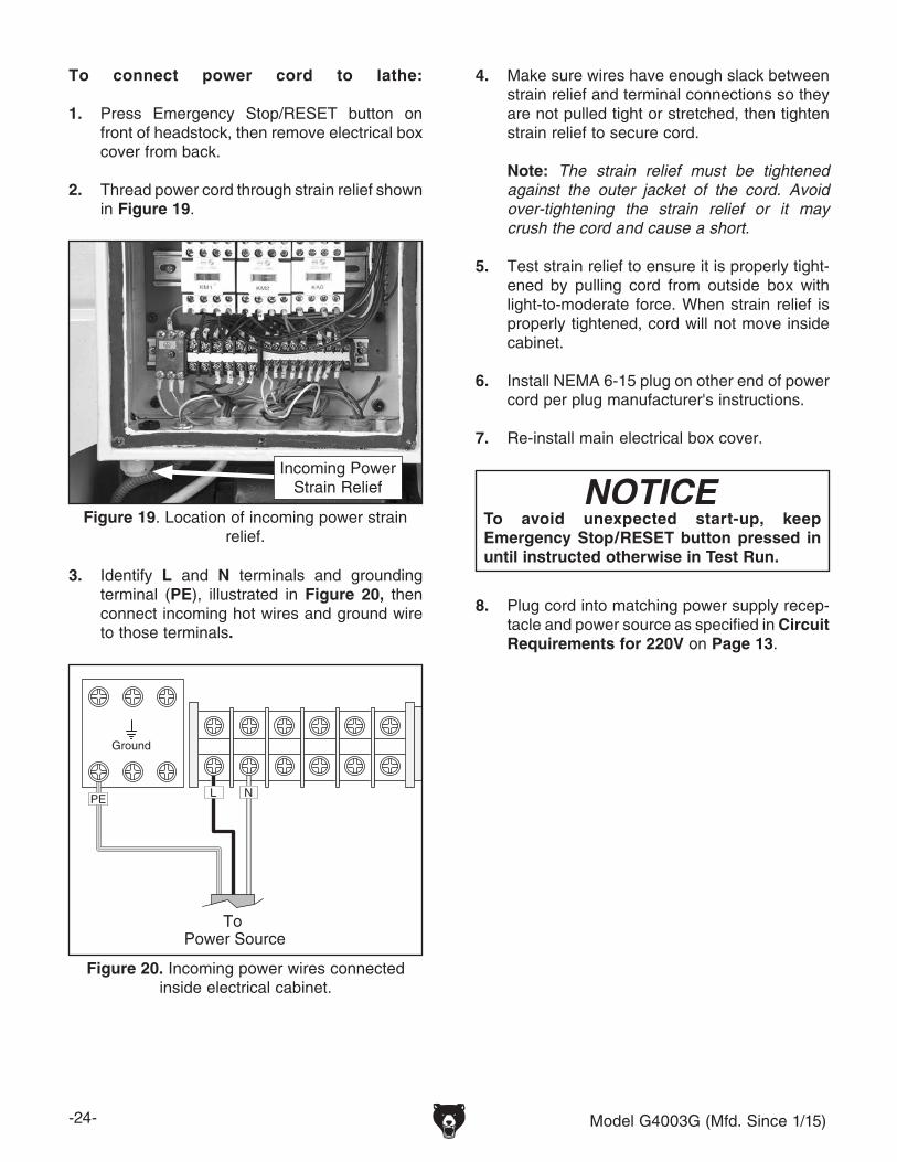
2. Thread power cord through strain relief shown in Figure 19.
Figure 19. Location of incoming power strain relief.
Incoming PowerStrain Relief
3. Identify L and N terminals and grounding terminal (PE), illustrated in Figure 20, then connect incoming hot wires and ground wire to those terminals.
Ground
To Power Source
PE L N
Figure 20. Incoming power wires connected inside electrical cabinet.
4. Make sure wires have enough slack between strain relief and terminal connections so they are not pulled tight or stretched, then tighten strain relief to secure cord.
Note: The strain relief must be tightened against the outer jacket of the cord. Avoid over-tightening the strain relief or it may crush the cord and cause a short.
5. Test strain relief to ensure it is properly tight-ened by pulling cord from outside box with light-to-moderate force. When strain relief is properly tightened, cord will not move inside cabinet.
6. Install NEMA 6-15 plug on other end of power cord per plug manufacturer's instructions.
7. Re-install main electrical box cover.
8. Plug cord into matching power supply recep-tacle and power source as specified in Circuit Requirements for 220V on Page 13.
To avoid unexpected start-up, keep Emergency Stop/RESET button pressed in until instructed otherwise in Test Run.

Model G4003G (Mfd. Since 1/15) -25-
3. To ensure carriage components do not unex-pectedly move during following steps, disen-gage half nut lever and apron feed selection lever (see Figure 21).
4. Rotate Emergency Stop/RESET button clock-wise so it pops out. The power lamp on con-trol panel should illuminate.
To test run your machine:
1. Make sure that chuck and jaws, if installed, are secure (refer to Chuck Installation on Page 30).
Note: If a chuck is not installed on the lathe, you do not need to install one for this test.
2. Make sure spindle lever is in OFF (center) position (see Figure 21).
Figure 21. Disengaging carriage components.
Engaged
HalfnutLever
DisengagedCross SlideDisengaged
Feed SelectionLever
Carriage
Half-Nut Lever is Pulled Up
(Disengaged)
Spindle Lever (OFF, Center
Position)
Feed SelectionLever is
Horizontal (Disengaged)
Test Run
Once assembly is complete, test run the machine to ensure it is properly connected to power and safety components are functioning correctly.
If you find an unusual problem during the test run, immediately stop the machine, disconnect it from power, and fix the problem BEFORE operating the machine again. The Troubleshooting table in the SERVICE section of this manual can help.
If you are unable to remedy a problem on your own, contact Tech Support at (570) 546-9663 or [email protected].
DO NOT start machine until all preceding setup instructions have been performed. Operating an improperly set up machine may result in malfunction or unexpect-ed results that can lead to serious injury, death, or machine/property damage.
Serious injury or death can result from using this machine BEFORE understanding its controls and related safety information. DO NOT operate, or allow others to operate, machine until the information is understood.
-26- Model G4003G (Mfd. Since 1/15)
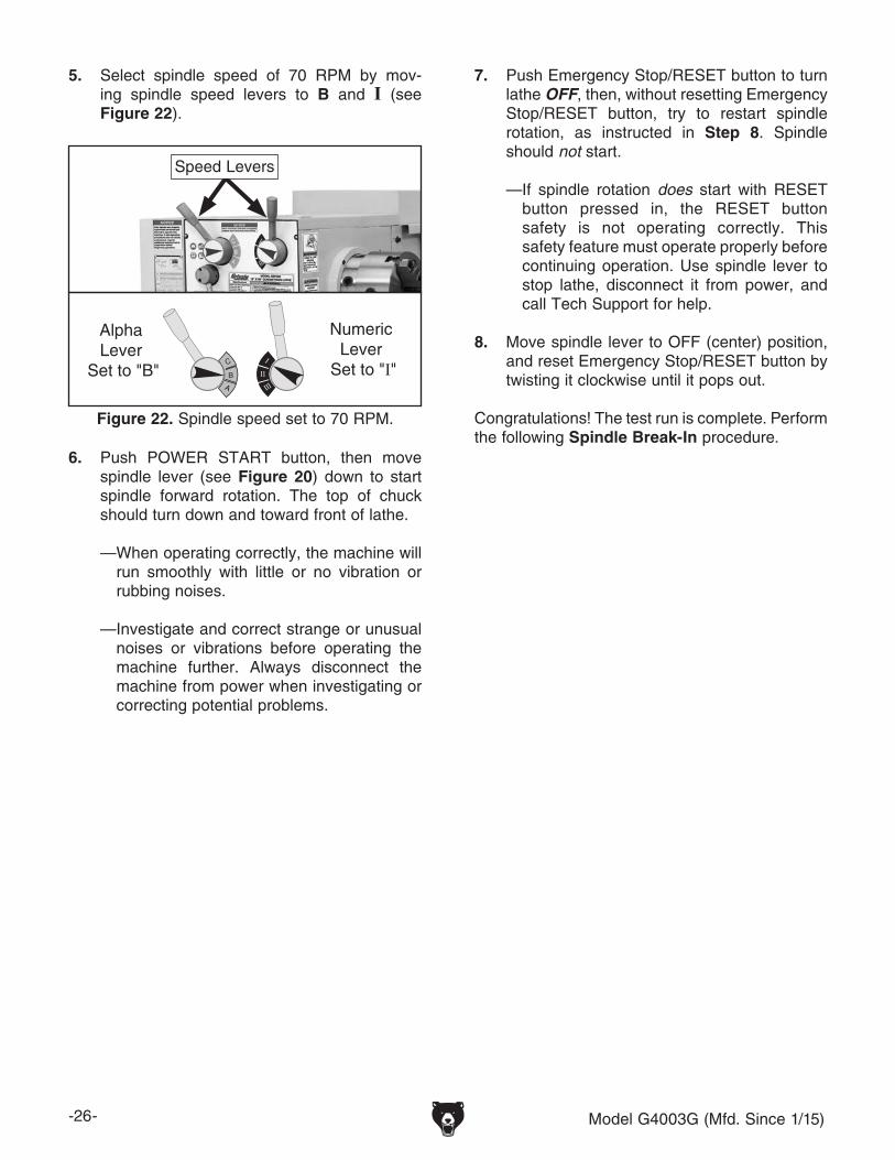
Figure 22. Spindle speed set to 70 RPM.
Speed Levers
C
B
A
I
II
III
Alpha Lever
Set to "B"
Numeric Lever
Set to "I"
7. Push Emergency Stop/RESET button to turn lathe OFF, then, without resetting Emergency Stop/RESET button, try to restart spindle rotation, as instructed in Step 8. Spindle should not start.
— If spindle rotation does start with RESET button pressed in, the RESET button safety is not operating correctly. This safety feature must operate properly before continuing operation. Use spindle lever to stop lathe, disconnect it from power, and call Tech Support for help.
8. Move spindle lever to OFF (center) position, and reset Emergency Stop/RESET button by twisting it clockwise until it pops out.
Congratulations! The test run is complete. Perform the following Spindle Break-In procedure.
5. Select spindle speed of 70 RPM by mov-ing spindle speed levers to B and I (see Figure 22).
6. Push POWER START button, then move spindle lever (see Figure 20) down to start spindle forward rotation. The top of chuck should turn down and toward front of lathe.
— When operating correctly, the machine will run smoothly with little or no vibration or rubbing noises.
— Investigate and correct strange or unusual noises or vibrations before operating the machine further. Always disconnect the machine from power when investigating or correcting potential problems.
Model G4003G (Mfd. Since 1/15) -27-
Spindle Break-In
To perform the spindle break-in:
1. Successfully complete Test Run procedure beginning on Page 25.
2. Run spindle at 70 RPM for 10 minutes in each direction (first forward and then reverse).
3. Turn lathe OFF. Move spindle speed levers to C and 1 for 200 RPM, and run lathe for 5 minutes in each direction.
Before subjecting the spindle to operational loads, it is essential to complete the break-in process. This helps maximize the life of spindle bearings and other precision components by thoroughly lubricating them before placing them under load.
After spindle break-in is complete, we recommend changing headstock and gearbox oil to remove any metal particles or debris that are present from the assembly and break-in process.
The break-in must be performed in succession with the Test Run procedure described in this manual, as the steps in that procedure prepare the lathe controls for the break-in process.
DO NOT perform this procedure indepen-dently of the Test Run section. The lathe could be seriously damaged if the controls are set differently than instructed in that section.
4. Repeat Step 3 for remaining spindle speeds, progressively increasing to highest speed.
5. Press Emergency Stop/RESET button to turn lathe OFF.
Congratulations! The spindle break-in is com-plete. We recommend changing the headstock and gearbox oil before operating the machine further (refer to Lubrication on Page 61).
The following adjustments have been made at the factory. However, because of the many variables involved with shipping, we recommend that you at least verify the following adjustments to ensure the best possible results from the lathe.
Step-by-step instructions for these adjustments can be found on the pages referenced below.
Factory adjustments that should be verified:
• Tailstock alignment (see Page 37).• Backlash adjustment (see Page 70).• Gib adjustments (see Page 71).
Recommended Adjustments

-28- Model G4003G (Mfd. Since 1/15)
SECTION 4: OPERATIONS
Operation Overview
The purpose of this overview is to provide the nov-ice machine operator with a basic understanding of how the machine is used during operation, so the machine controls/components discussed later in this manual are easier to understand.
Due to the generic nature of this overview, it is not intended to be an instructional guide. To learn more about specific operations, read this entire manual, seek additional training from experienced machine operators, and do additional research outside of this manual by reading "how-to" books, trade magazines, or websites.
If you are not experienced with this type of machine, WE STRONGLY RECOMMEND that you seek additional training outside of this manual. Read books/magazines or get formal training before beginning any proj-ects. Regardless of the content in this sec-tion, Grizzly Industrial will not be held liable for accidents caused by lack of training.
To complete a typical operation, the operator does the following:
1. Puts on safety glasses, rolls up sleeves, removes jewelry, and secures any clothing, jewelry, or hair that could get entangled in moving parts.
2. Examines workpiece to make sure it is suit-able for turning, then securely mounts it in lathe.
3. Installs tooling, aligns it with workpiece, then backs it away to establish a safe startup clearance.
4. Removes all setup tools from lathe.
5. Checks for safe clearances by rotating workpiece by hand at least one full revolution.
6. Moves slides to where they will be used dur-ing operation.
7. Sets correct spindle speed for operation.
8. If using power feed, selects proper feed rate for the operation.
9. Resets Emergency Stop/RESET button, then starts spindle rotation.
10. Uses carriage handwheels or power feed options to move tooling into workpiece for operations.
11. When finished cutting, moves spindle lever to OFF position, waits for spindle to completely stop, then removes workpiece.
To reduce your risk of serious injury, read this entire manual BEFORE using machine.
To reduce the risk of eye injury from flying chips always wear safety glasses when operating lathe.

Model G4003G (Mfd. Since 1/15) -29-
Chuck & Faceplate Mounting
Chuck Safety & Support Devices
Because chucks are heavy and often awkward to hold, some kind of lifting, support, or protec-tive device should be used during installation or removal. The weight and size of the chuck will determine the appropriate device to use (refer to the following figure for examples).
This lathe is equipped with a D1-type spindle nose. This type of spindle uses camlocks that are adjusted with a chuck key to securely mount a chuck or faceplate with repeatable precision and ease.
This lathe ships with the 3-jaw chuck installed. This is a scroll-type chuck where all three jaws move in unison when the chuck key is used.
The included 4-jaw chuck features independent jaws, which are used for square or unevenly-shaped stock, and to mount work that needs to be adjusted to near-zero total indicated runout.
The included faceplate has slots for T-bolts that hold standard or custom clamping hardware. With the correct clamping hardware, a faceplate offers a wide range of uses, including machining non-concentric workpieces, straight turning between centers, off-center turning, and boring.
Pre-Threaded Holefor Lifting Eye
Way SlotJaw Slot
Plywood & 2x4 Chuck Cradle
Plywood Chuck Cradle (Straight Cuts)
Plywood Chuck Cradle (Curved Cuts)
Fabricated SteelLifting Hook
Solid BlockChuck Cradle
Plywood ProtectionPlate for ChucksInstalled by Hand
MEDIUM-SIZE, HEAVY CHUCKS
LARGE, VERY HEAVY CHUCKS
SMALL, LIGHTWEIGHT CHUCKS
Figure 23. Examples of common devices used during chuck installation and removal.
Dropping a chuck can result in amputation, serious crushing injuries, or property dam-age. Always use a support or protective device to reduce this risk during installation or removal.
Never use spindle speeds faster than the chuck RPM rating or the safe limits of your workpiece. Excessive spindle speeds greatly increase the risk of the workpiece or chuck being thrown from the machine with deadly force!

-30- Model G4003G (Mfd. Since 1/15)
Chuck Installation
Figure 25. Cam line positioned between the "V" marks after the camlocks are fully tightened.
Cam line between “V”s
5. Incrementally tighten camlocks in criss-cross or star pattern to ensure that chuck seats evenly against spindle.
6. When chuck is fully seated and all camlocks are tight, verify that cam line is between the two “V” marks on spindle nose, as shown in following figure.
Figure 26. Correcting an improperly installed stud.
Stud Too High:Turn In
One-Turn
Stud Too Low: Turn OutOne-Turn
INCORRECT INCORRECT
— If cam line is NOT between "V" marks when camlock is tight, stud may be installed at incorrect height. To fix this, adjust stud height as shown in following figure. Make sure to re-install stud cap screw afterward.
— If adjusting stud height does not correct problem, try swapping stud positions on chuck.
Figure 24. Inserting camlock studs into spindle cam holes.
INCORRECTCORRECT
To ensure accurate work, it is extremely important to make sure the spindle nose and chuck mating surfaces/tapers are clean. Even a small amount of lint or debris can affect accuracy.
The chuck is properly installed when all camlocks are tight, the spindle and chuck tapers firmly lock together, and the back of the chuck is firmly seated against the face of the spindle all the way around—without any gaps.
To install chuck:
1. DISCONNECT MACHINE FROM POWER!
2. Use appropriate lifting, support, or protective device to protect ways and support chuck during installation process (refer to Chuck Safety & Support Devices).
3. Clean and lightly oil camlock studs, then thor-oughly clean mating surfaces of spindle and chuck.
4. Install chuck by inserting camlock studs straight into spindle cam holes.
Important: Avoid inserting the studs by piv-oting them in from an angle or rotating the spindle. This can damage studs or spindle cam holes.
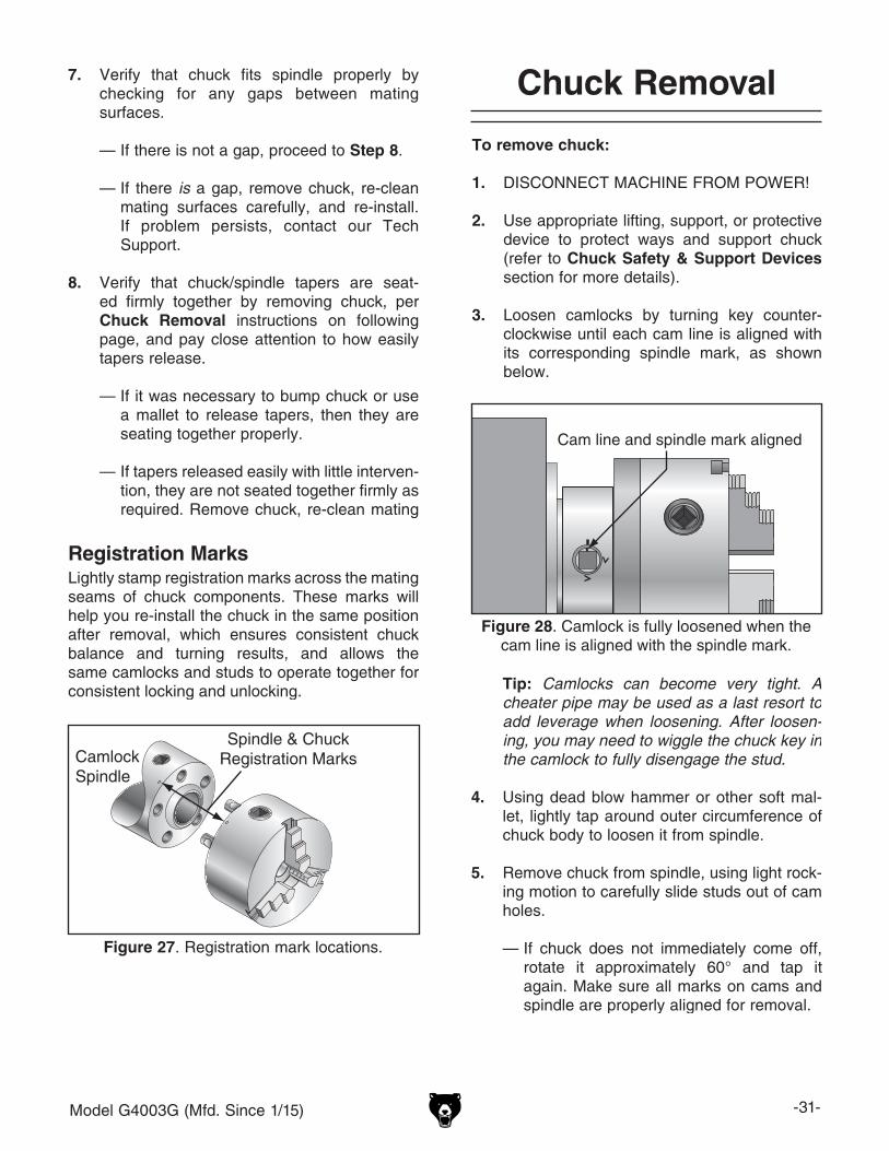
Model G4003G (Mfd. Since 1/15) -31-
Chuck Removal7. Verify that chuck fits spindle properly by checking for any gaps between mating surfaces.
— If there is not a gap, proceed to Step 8.
— If there is a gap, remove chuck, re-clean mating surfaces carefully, and re-install. If problem persists, contact our Tech Support.
8. Verify that chuck/spindle tapers are seat-ed firmly together by removing chuck, per Chuck Removal instructions on following page, and pay close attention to how easily tapers release.
— If it was necessary to bump chuck or use a mallet to release tapers, then they are seating together properly.
— If tapers released easily with little interven-tion, they are not seated together firmly as required. Remove chuck, re-clean mating surfaces carefully, and re-install. If prob-lem persists, contact our Tech Support.
To remove chuck:
1. DISCONNECT MACHINE FROM POWER!
2. Use appropriate lifting, support, or protective device to protect ways and support chuck (refer to Chuck Safety & Support Devices section for more details).
3. Loosen camlocks by turning key counter-clockwise until each cam line is aligned with its corresponding spindle mark, as shown below.
Cam line and spindle mark aligned
Figure 28. Camlock is fully loosened when the cam line is aligned with the spindle mark.
Tip: Camlocks can become very tight. A cheater pipe may be used as a last resort to add leverage when loosening. After loosen-ing, you may need to wiggle the chuck key in the camlock to fully disengage the stud.
4. Using dead blow hammer or other soft mal-let, lightly tap around outer circumference of chuck body to loosen it from spindle.
5. Remove chuck from spindle, using light rock-ing motion to carefully slide studs out of cam holes.
— If chuck does not immediately come off, rotate it approximately 60° and tap it again. Make sure all marks on cams and spindle are properly aligned for removal.
Registration MarksLightly stamp registration marks across the mating seams of chuck components. These marks will help you re-install the chuck in the same position after removal, which ensures consistent chuck balance and turning results, and allows the same camlocks and studs to operate together for consistent locking and unlocking.
Figure 27. Registration mark locations.
CamlockSpindle
Spindle & ChuckRegistration Marks

-32- Model G4003G (Mfd. Since 1/15)
This 3-jaw, scroll-type chuck has an internal scroll-gear that moves all jaws in unison when adjusted with the chuck key. This chuck holds cylindrical parts on-center with the axis of spindle rotation and can be rotated at high speeds if the workpiece is properly clamped and balanced.
Never mix jaw types or positions to accommodate an odd-shaped workpiece. The chuck will spin out of balance and may throw the workpiece! Instead, use an independent jaw chuck or a faceplate.
Scroll Chuck Clamping
InsufficientJaw Clamping
UnstableWorkpiece
Bar Stock
Cylinder
Unsafe Jaw Position
Poor ScrollGear Engagement
Safer Inside Jaw Use
Unsafe InsideJaw Use
Unsafe Jaw Position
Safer Outside Jaw Use
Poor Scroll Gear EngagementUnsafe Jaw Position and
Poor ScrollGear Engagement
Poor Grip
UnstableWorkpiece
ShallowBar Stock
ShallowBar Stock
Safer Outside Jaw Use
Safer InsideJaw Use
CORRECT
CORRECT
CORRECT
CORRECT
INCORRECT
INCORRECT
INCORRECT
INCORRECT
Figure 29. Jaw selection and workpiece holding.
Chuck Jaw Reversal
This chuck has 2-piece jaws that consist of a top jaw and a master jaw. The top jaw can be removed, rotated 180°, and re-installed in the reverse position for additional work-holding options. When reversing the top jaws, always keep them matched with their original master jaw to ensure the best fit.
To reverse 2-piece jaws:
1. DISCONNECT MACHINE FROM POWER!
2. Remove cap screws that secure top jaw to master (bottom) jaw.
3. Remove top jaw, rotate it 180°, then re-install it with longest cap screw in tallest portion of jaw.
4. Repeat Steps 2–3 with each remaining jaw (we recommend only reversing one jaw at a time to keep all original parts together).
Master Jaw
Rotate Top Jaw 180º
Long Cap ScrewShort Cap Screw
Figure 30. Reversing the chuck jaws.
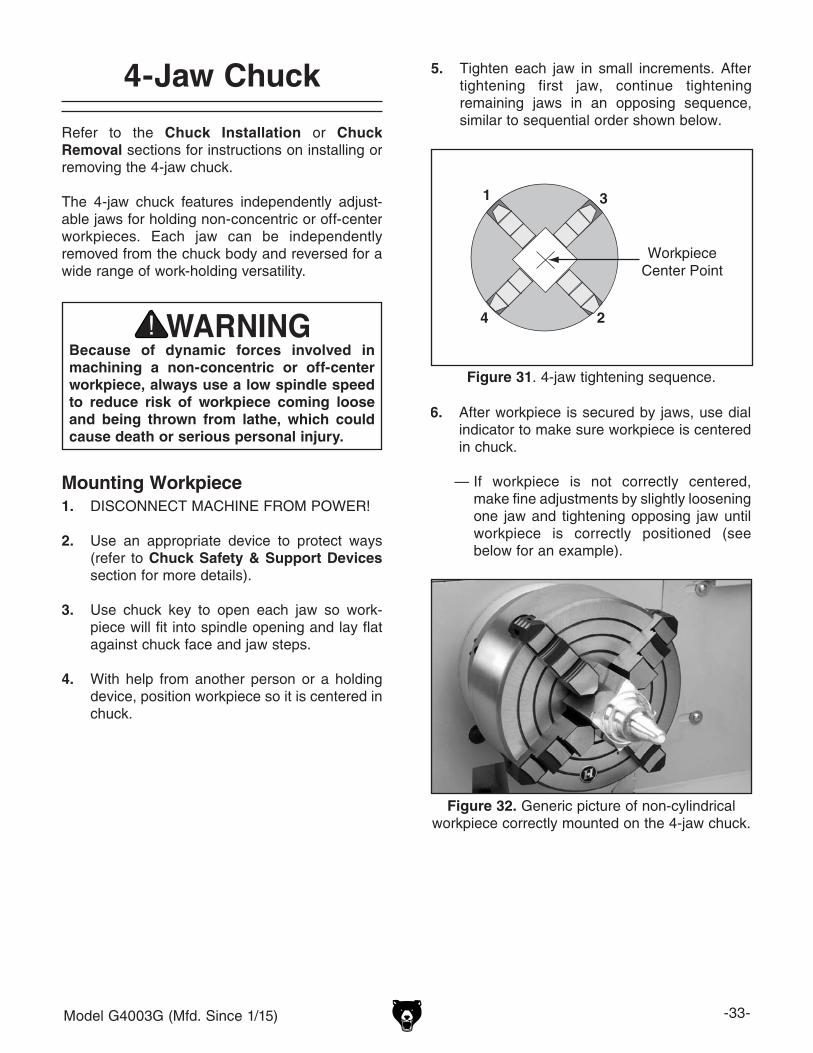
Model G4003G (Mfd. Since 1/15) -33-
4-Jaw Chuck
Refer to the Chuck Installation or Chuck Removal sections for instructions on installing or removing the 4-jaw chuck.
The 4-jaw chuck features independently adjust-able jaws for holding non-concentric or off-center workpieces. Each jaw can be independently removed from the chuck body and reversed for a wide range of work-holding versatility.
Because of dynamic forces involved in machining a non-concentric or off-center workpiece, always use a low spindle speed to reduce risk of workpiece coming loose and being thrown from lathe, which could cause death or serious personal injury.
Mounting Workpiece1. DISCONNECT MACHINE FROM POWER!
2. Use an appropriate device to protect ways (refer to Chuck Safety & Support Devices section for more details).
3. Use chuck key to open each jaw so work-piece will fit into spindle opening and lay flat against chuck face and jaw steps.
4. With help from another person or a holding device, position workpiece so it is centered in chuck.
5. Tighten each jaw in small increments. After tightening first jaw, continue tightening remaining jaws in an opposing sequence, similar to sequential order shown below.
Figure 31. 4-jaw tightening sequence.
1
2
3
4
WorkpieceCenter Point
Figure 32. Generic picture of non-cylindrical workpiece correctly mounted on the 4-jaw chuck.
6. After workpiece is secured by jaws, use dial indicator to make sure workpiece is centered in chuck.
— If workpiece is not correctly centered, make fine adjustments by slightly loosening one jaw and tightening opposing jaw until workpiece is correctly positioned (see below for an example).

-34- Model G4003G (Mfd. Since 1/15)
Faceplate
Refer to the prior Chuck Installation and Chuck Removal subsections for instructions on installing or removing the faceplate.
The faceplate included with your lathe can be used for a wide range of operations, including machining non-concentric workpieces, straight turning between centers, off-center turning, and boring.
The tools needed for mounting a workpiece will vary depending on the type of setup you have.
To mount a non-concentric workpiece to a faceplate:
1. DISCONNECT MACHINE FROM POWER!
2. Position appropriate device across bed ways to protect them from any potential damage from workpiece contact during installation.
3. With help from another person or holding device to support workpiece, position it onto faceplate and clamp it in place with a mini-mum of three independent clamping devices (see below for an example).
Be sure to take into account rotational and cutting forces that will be applied to work-piece when clamping it to faceplate. If neces-sary, use counter-weights to balance assem-bly and use a dial indicator to make sure workpiece is properly positioned for your operation.
Machining non-concentric workpieces at high speeds could cause workpiece to be thrown from lathe with deadly force. To reduce this risk, only machine non-concentric workpieces at low speeds and clamp counter-weights to the faceplate to balance it.
Failure to properly secure workpiece to faceplate could cause workpiece to be thrown from lathe with deadly force. To reduce this risk, use minimum of THREE independent clamping devices to hold workpiece onto faceplate.
Figure 33. Generic picture of workpiece clamped in a faceplate.
Clamp
Faceplate
Non-CylindricalWorkpiece

Model G4003G (Mfd. Since 1/15) -35-
Tailstock
The tailstock (see Figure 34) is typically used to support long workpieces by means of a live or dead center (refer to Centers on Page 39 in the following section). It can also be used to hold a drill or chuck to bore holes in the center of a part. Custom arbors and tapers can also be cut on your lathe by using the offset tailstock adjustment.
Also, a torque wrench can be used with the tailstock for repeating super-accurate vertical alignment.
Quill Handwheel Graduated DialIncrements ................................................. 0.001"One Full Revolution ................................... 0.100"
Increments on QuillInch ...........................0"–4 " in 0.100" Increments
Positioning Tailstock1. Rotate tailstock lock lever clockwise (facing
machine) to unlock tailstock from bedways.
2. Slide tailstock to desired position by pushing it along the bedways.
3. Rotate tailstock lock lever counterclockwise to lock tailstock against bedways.
Optional: To precisely secure the tailstock, mount a 1⁄2" drive torque wrench in the square drive shown in Figure 34, then tighten the tailstock to 40 lbs/ft of torque. The center point will be drawn down as much as 0.006". Do not exceed the max torque or damage to ways and tailstock will occur.
Using Quill1. Rotate quill lock lever counterclockwise to
loosen quill.
2. Turn quill handwheel clockwise to move quill toward spindle or counterclockwise to move it away from spindle.
3. Rotate quill lock lever clockwise to secure quill.
Figure 34. Tailstock and quill lock levers in locked position.
1⁄2" Square Drive Lock-Down Quill Handwheel
Quill Lock Lever
Tailstock Lock Lever

-36- Model G4003G (Mfd. Since 1/15)
Figure 36. Example photo of inserting tool with tang into tailstock.
Tang
To install tooling in tailstock:
1. With tailstock locked in place, unlock quill, then use handwheel to extend it approxi-mately 1".
2. Thoroughly clean and dry tapered mating surfaces of quill and center, making sure that no lint or oil remain on tapers.
Note: If tapered tool shaft has a tang, align it with slot in back of quill before seating it.
3. With a firm and quick motion, insert tool into quill. Check to see if it is firmly seated by attempting to twist it—a firmly seated tool will not twist.
4. Unlock tailstock and move it until tip of tool is close to, but not touching workpiece, then relock tailstock.
5. Start spindle rotation, unlock quill lock lever, then turn quill handwheel clockwise to feed tool into workpiece.
Removing Tooling1. Use shop rag to hold tool.
2. Rotate quill handwheel counterclockwise until tool is forced out of quill.
— If tool does not come loose by retracting quill, extend quill and use drift key in slot shown in Figure below to remove tool.
Figure 37. Drift key slot in the side of the quill.
Drift Key Slot
However, other tooling without tangs, such as the four remaining tools shown previously, can still be used if the potential load will not exceed the strength of the tapered fit. For example, this includes smaller drill chucks, drill bits, and cen-ters.
Note: If the tooling has an open hole in the end but is too short to be exposed in the drift slot for removal, then a screw can be threaded in the end of the tool to provide a solid surface for the quill pin to push against when the quill is retracted for tool removal. Otherwise, removal of such tooling may be difficult.
Installing ToolingThis tailstock uses a quill with an MT#3 taper that has a lock slot in the back of the bore that accepts tang arbors and drill bits (see the Figures below for examples).
Figure 35. Types of tapered arbors and tooling.
ScrewEnd
SolidEnd
OpenEnd
SolidEnd
Tang

Model G4003G (Mfd. Since 1/15) -37-
Offsetting TailstockThe tailstock quill can be offset from the spindle centerline for turning tapers. Offsetting the quill toward the front of the lathe results in a taper at the tailstock end. Conversely, offsetting the quill toward the back of the lathe results in a taper at the spindle end.
Tools Needed QtyHex Wrench 4mm .............................................. 1
To offset the tailstock:
1. Rotate the adjustment set screws (shown in Figure 38) in the opposite directions for the desired offset.
Note: The marks on the offset indicator (see Figure 38) are arbitrary. For a precise offset, use a dial indicator to check quill movement while adjusting the screws.
Turn CCW
Turn CCW
Turn CW
Turn CW
Figure 38. Set screw adjustment in relation to tailstock movement.
AdjustmentSet Screw
(1 of 2)
OffsetIndicator
Aligning Tailstock to Spindle CenterlineThis is an essential adjustment that should be ver-ified or performed each time the tailstock is used to turn concentric workpieces between centers or immediately after offsetting the tailstock when turning a taper. If the tailstock is not aligned with the spindle centerline when it is supposed to be, turning results will be inaccurate along the length of the workpiece.
Items Needed QtyHex Wrench 4mm .............................................. 1Round Stock 2" x 6" .......................................... 2Precision Level .................................................. 1
Figure 39. Turning a dead center.
To align tailstock to spindle centerline:
1. Use precision level to make sure bedway is level from side to side and from front to back.
— If bedway is not level, correct this condition before continuing with this procedure (refer to Leveling section in this manual).
2. Center drill both ends of a piece of round stock, then set it aside for use in Step 5.
3. Use another piece of round stock to make a dead center. Turn it to a 60° point, as illus-trated below.

-38- Model G4003G (Mfd. Since 1/15)
4. Install center in tailstock.
5. Attach lathe dog to test stock from Step 2, then mount it between centers, as shown below.
Figure 40. Example photo of stock mounted between the centers.
6. Turn 0.010" off stock diameter.
7. Mount test or dial indicator so that plunger is on tailstock quill.
Note: If necessary in the following step, refer to the Offsetting Tailstock subsection for detailed instructions.
8. Use calipers to measure both ends of work-piece.
— If test stock is thicker at tailstock end, move tailstock toward front of lathe 1⁄2 the dis-tance of taper amount, as shown below.
Move tailstock toward front of lathe 1/2 the
amount of taper.
Looking down from above.
Figure 41. Adjust tailstock toward the operator.
— If test stock is thinner at tailstock end, move tailstock toward back of lathe 1⁄2 the distance of taper amount, as shown below.
Looking down from above.
Move tailstock toward back of lathe 1/2 the
amount of taper.
Figure 42. Adjust tailstock away from the operator.
9. Repeat Steps 6–8 until desired accuracy is achieved.

Model G4003G (Mfd. Since 1/15) -39-
Figure 43 shows the MT#3 dead centers and live center included with the lathe. In addition, an MT#5–MT#3 tapered spindle sleeve is included for mounting in the spindle.
Dead CentersA dead center is a one-piece center that does not rotate with the workpiece and is used to support long, slender workpieces
Use the dead center in the spindle for operations where the workpiece rotates with the center and does not generate friction.
The carbide-tipped dead center can better with-stand the effects of friction and is best used in the tailstock where the workpiece will rotate against it. The tip of the center must be generously lubri-cated during the operation to avoid premature wear and maximize smooth operation. Using low spindle speeds will also reduce the heat and wear from friction.
Centers
Figure 43. Adapter sleeve and centers.
Adapter Sleeve
DeadCenter Live
Center
Carbide-Tipped Dead Center
Live CentersA live center has bearings that allow the centertip and the workpiece to rotate together; it can beinstalled in the tailstock quill for higher speeds.
Mounting Dead Center in Spindle1. DISCONNECT LATHE FROM POWER!
2. Thoroughly clean and dry the tapered mating surfaces of spindle bore, adapter sleeve, and center, making sure that no lint or oil remains on tapers.
Note: This will prevent the tapered surfaces from seizing due to operational pressures, which could make it very difficult to remove the center.
3. Mount faceplate onto spindle.
4. Insert center into sleeve, then insert sleeve into spindle bore through faceplate.
Figure 44 shows an example photo of a dead center installed in spindle, using a lathe dog and faceplate for turning between centers.
Figure 44. Example photo of using a dead center with a faceplate and lathe dog.
LatheDog
Dead Center
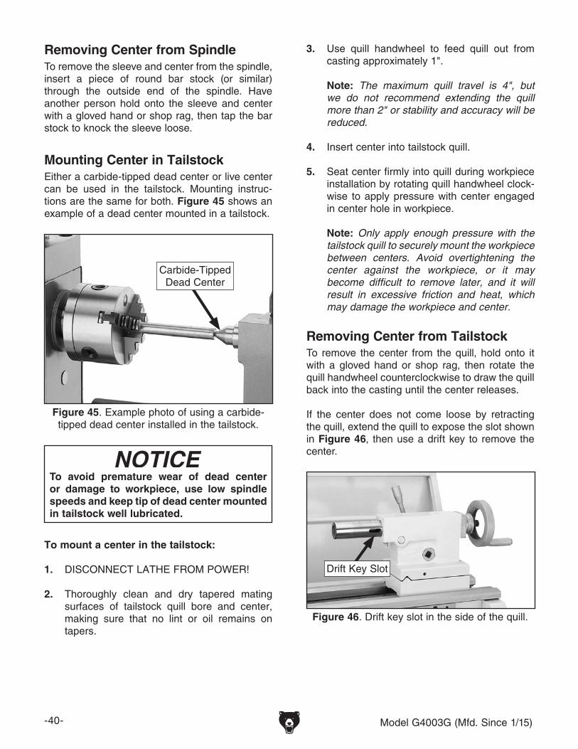
-40- Model G4003G (Mfd. Since 1/15)
Removing Center from SpindleTo remove the sleeve and center from the spindle, insert a piece of round bar stock (or similar) through the outside end of the spindle. Have another person hold onto the sleeve and center with a gloved hand or shop rag, then tap the bar stock to knock the sleeve loose.
Mounting Center in TailstockEither a carbide-tipped dead center or live center can be used in the tailstock. Mounting instruc-tions are the same for both. Figure 45 shows an example of a dead center mounted in a tailstock.
3. Use quill handwheel to feed quill out from casting approximately 1".
Note: The maximum quill travel is 4", but we do not recommend extending the quill more than 2" or stability and accuracy will be reduced.
4. Insert center into tailstock quill.
5. Seat center firmly into quill during workpiece installation by rotating quill handwheel clock-wise to apply pressure with center engaged in center hole in workpiece.
Note: Only apply enough pressure with the tailstock quill to securely mount the workpiece between centers. Avoid overtightening the center against the workpiece, or it may become difficult to remove later, and it will result in excessive friction and heat, which may damage the workpiece and center.
Removing Center from TailstockTo remove the center from the quill, hold onto it with a gloved hand or shop rag, then rotate the quill handwheel counterclockwise to draw the quill back into the casting until the center releases.
If the center does not come loose by retracting the quill, extend the quill to expose the slot shown in Figure 46, then use a drift key to remove the center.
To mount a center in the tailstock:
1. DISCONNECT LATHE FROM POWER!
2. Thoroughly clean and dry tapered mating surfaces of tailstock quill bore and center, making sure that no lint or oil remains on tapers.
To avoid premature wear of dead center or damage to workpiece, use low spindle speeds and keep tip of dead center mounted in tailstock well lubricated.
Figure 45. Example photo of using a carbide-tipped dead center installed in the tailstock.
Carbide-TippedDead Center
Figure 46. Drift key slot in the side of the quill.
Drift Key Slot

Model G4003G (Mfd. Since 1/15) -41-
Mounting Workpiece Between Centers1. DISCONNECT LATHE FROM POWER!
2. Drill center holes in both ends of the workpiece.
3. Install dead center in spindle with a lathe dog and a chuck or faceplate, then install a live center or carbide-tipped dead center in tailstock.
4. Lubricate workpiece center holes, then mount it between centers and hold it in place with light pressure from tailstock center.
5. Seat center firmly into quill by rotating quill handwheel clockwise to apply pres-sure against workpiece (see the example in Figure 47).
Figure 47. Example photo of a workpiece mounted between the centers.
Only apply enough pressure to securely mount the workpiece between centers. Avoid over-tight-ening the center against the workpiece, or it may become difficult to remove later. Also, over-tightening will result in excessive friction and heat, which may damage the workpiece or center.
The drill chuck attaches to the tailstock quill with the included B16 to MT#3 arbor.
Matched tapers on the arbor and the inside of the chuck create a semi-permanent assembly when properly joined. The drill chuck can accept tooling from 1⁄16"–1⁄2". If you would like to use a different chuck in the future, we recommend obtaining a new arbor.
The procedure for mounting and removing the chuck and arbor from the tailstock quill is the same as for a center.
To join drill chuck and arbor:
1. Use acetone or lacquer thinner to clean drill chuck and arbor mating surfaces, especially the bore.
2. Retract chuck jaws completely into chuck.
3. Insert small end of arbor into chuck.
4. Hold assembly by the arbor and tap chuck onto a block of wood with medium force, as illustrated in Figure 48.
Joining Drill Chuck & Arbor
Figure 48. Tapping drill chuck/arbor on block of wood.
5. Attempt to separate drill chuck and arbor by hand —if they separate, repeat Steps 3–4.
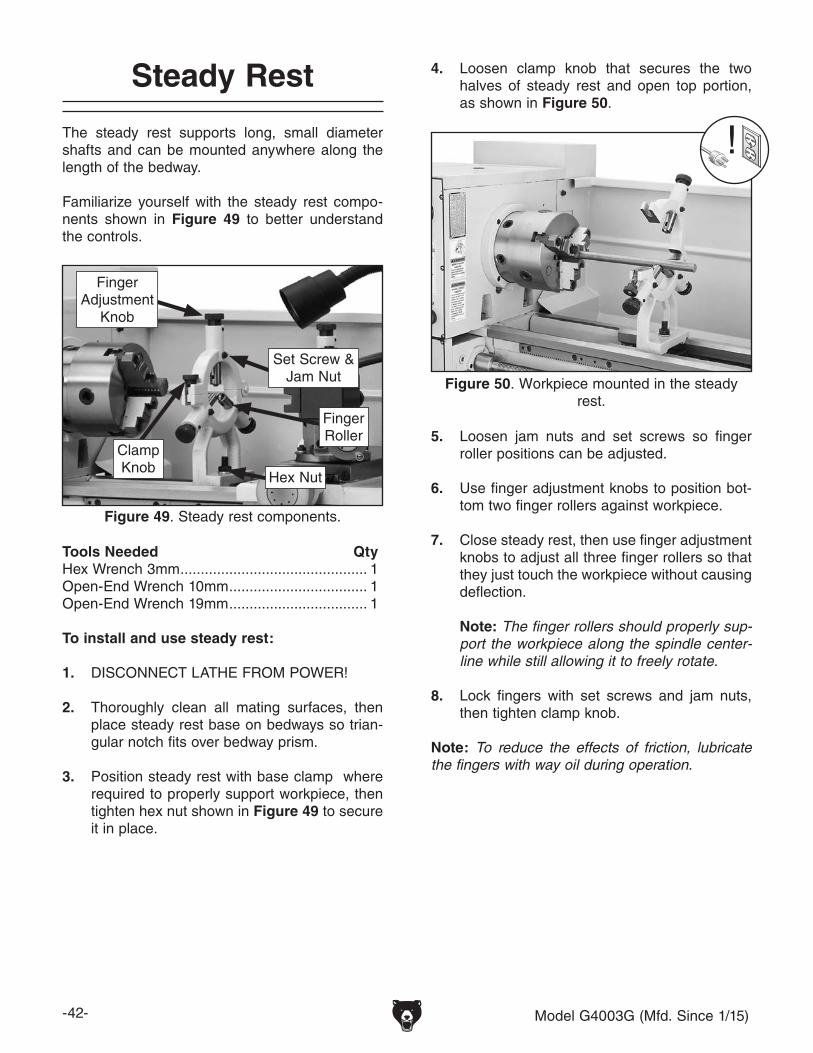
-42- Model G4003G (Mfd. Since 1/15)
The steady rest supports long, small diameter shafts and can be mounted anywhere along the length of the bedway.
Familiarize yourself with the steady rest compo-nents shown in Figure 49 to better understand the controls.
Steady Rest
Tools Needed QtyHex Wrench 3mm .............................................. 1Open-End Wrench 10mm .................................. 1Open-End Wrench 19mm .................................. 1
To install and use steady rest:
1. DISCONNECT LATHE FROM POWER!
2. Thoroughly clean all mating surfaces, then place steady rest base on bedways so trian-gular notch fits over bedway prism.
3. Position steady rest with base clamp where required to properly support workpiece, then tighten hex nut shown in Figure 49 to secure it in place.
Figure 49. Steady rest components.
Set Screw & Jam Nut
Finger Adjustment
Knob
Finger Roller
Hex Nut
ClampKnob
4. Loosen clamp knob that secures the two halves of steady rest and open top portion, as shown in Figure 50.
5. Loosen jam nuts and set screws so finger roller positions can be adjusted.
6. Use finger adjustment knobs to position bot-tom two finger rollers against workpiece.
7. Close steady rest, then use finger adjustment knobs to adjust all three finger rollers so that they just touch the workpiece without causing deflection.
Note: The finger rollers should properly sup-port the workpiece along the spindle center-line while still allowing it to freely rotate.
8. Lock fingers with set screws and jam nuts, then tighten clamp knob.
Note: To reduce the effects of friction, lubricate the fingers with way oil during operation.
Figure 50. Workpiece mounted in the steady rest.
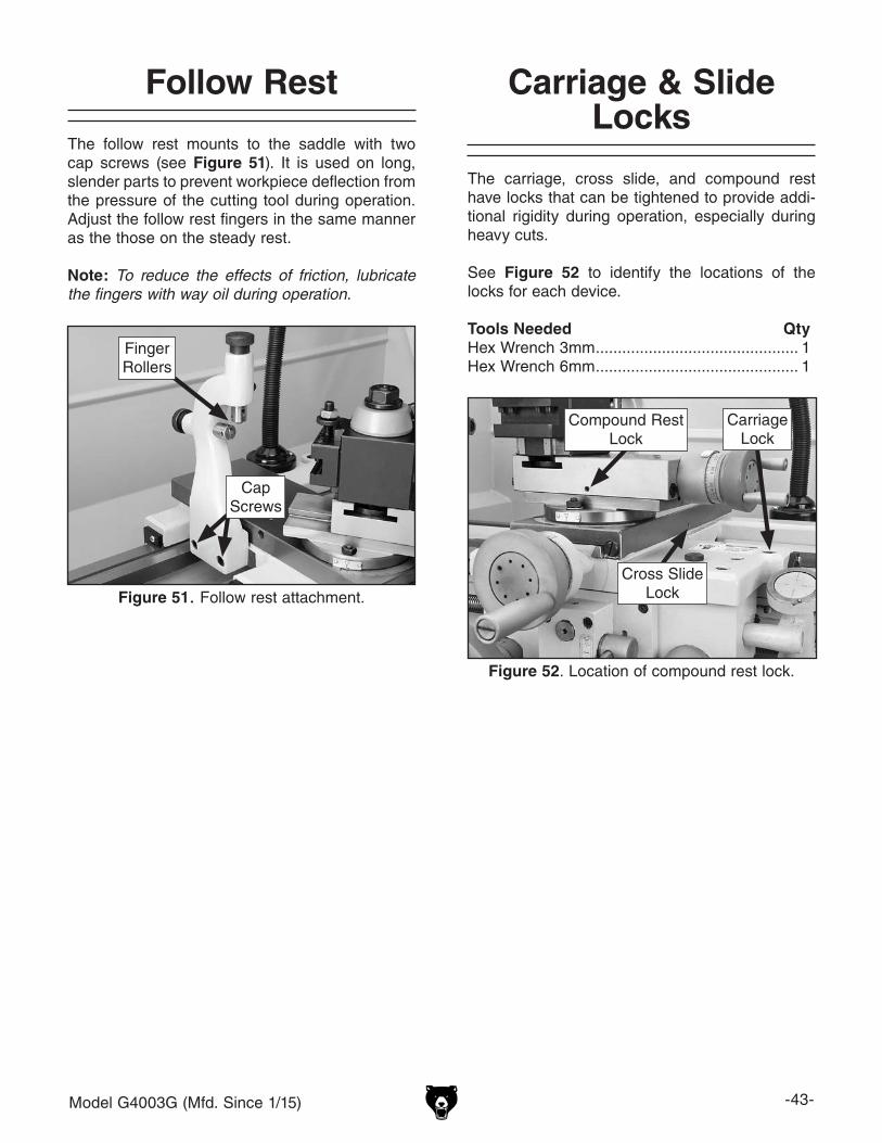
Model G4003G (Mfd. Since 1/15) -43-
The follow rest mounts to the saddle with two cap screws (see Figure 51). It is used on long, slender parts to prevent workpiece deflection from the pressure of the cutting tool during operation. Adjust the follow rest fingers in the same manner as the those on the steady rest.
Note: To reduce the effects of friction, lubricate the fingers with way oil during operation.
Follow Rest
Figure 51. Follow rest attachment.
CapScrews
Finger Rollers
The carriage, cross slide, and compound rest have locks that can be tightened to provide addi-tional rigidity during operation, especially during heavy cuts.
See Figure 52 to identify the locations of the locks for each device.
Tools Needed QtyHex Wrench 3mm .............................................. 1Hex Wrench 6mm .............................................. 1
Carriage & Slide Locks
Figure 52. Location of compound rest lock.
CarriageLock
Compound RestLock
Cross SlideLock
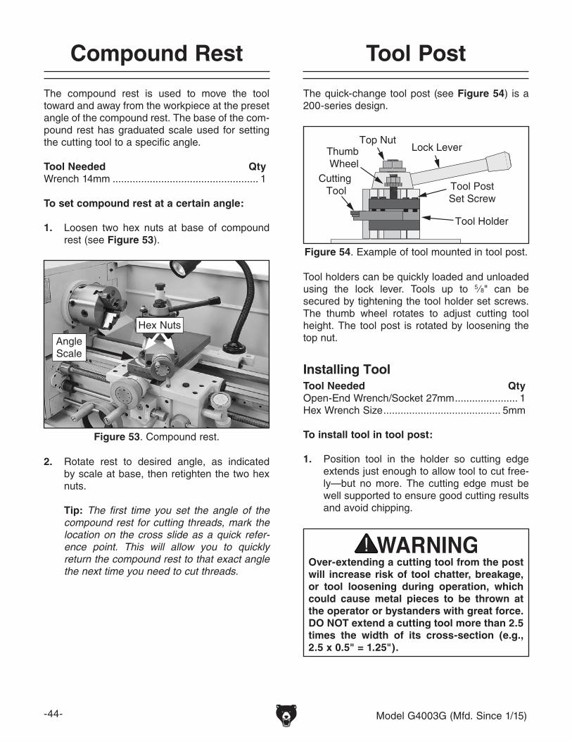
-44- Model G4003G (Mfd. Since 1/15)
2. Rotate rest to desired angle, as indicated by scale at base, then retighten the two hex nuts.
Tip: The first time you set the angle of the compound rest for cutting threads, mark the location on the cross slide as a quick refer-ence point. This will allow you to quickly return the compound rest to that exact angle the next time you need to cut threads.
The compound rest is used to move the tool toward and away from the workpiece at the preset angle of the compound rest. The base of the com-pound rest has graduated scale used for setting the cutting tool to a specific angle.
Tool Needed QtyWrench 14mm ................................................... 1
To set compound rest at a certain angle:
1. Loosen two hex nuts at base of compound rest (see Figure 53).
Compound Rest
Figure 53. Compound rest.
Hex Nuts
Angle Scale
The quick-change tool post (see Figure 54) is a 200-series design.
Figure 54. Example of tool mounted in tool post.
Cutting Tool Tool Post
Set Screw
Tool Holder
Thumb Wheel
Top NutLock Lever
Tool Post
Over-extending a cutting tool from the post will increase risk of tool chatter, breakage, or tool loosening during operation, which could cause metal pieces to be thrown at the operator or bystanders with great force. DO NOT extend a cutting tool more than 2.5 times the width of its cross-section (e.g., 2.5 x 0.5" = 1.25").
Tool holders can be quickly loaded and unloaded using the lock lever. Tools up to 5⁄8" can be secured by tightening the tool holder set screws. The thumb wheel rotates to adjust cutting tool height. The tool post is rotated by loosening the top nut.
Installing ToolTool Needed QtyOpen-End Wrench/Socket 27mm ...................... 1Hex Wrench Size ......................................... 5mm
To install tool in tool post:
1. Position tool in the holder so cutting edge extends just enough to allow tool to cut free-ly—but no more. The cutting edge must be well supported to ensure good cutting results and avoid chipping.

Model G4003G (Mfd. Since 1/15) -45-
There are a number of ways to check and align the cutting tool to the spindle centerline. If nec-essary, you can raise the cutting tool by placing steel shims underneath it. The shims should be as long and as wide as the cutting tool to properly support it.
Below are two common methods:
• Move the tailstock center over the cross slide and use a fine ruler to measure the distance from the surface of the cross slide to the tip of the center. Adjust the cutting tool height so it is the same distance above the cross slide as the tailstock center.
• Align the tip of the cutting tool with a tailstock center, as described in the following pro-cedure. For this to work, the tailstock must be aligned to the spindle centerline (refer to Aligning Tailstock To Spindle Centerline on Page 37 for detailed instructions).
Cutting Tool
SpindleCenter
Line
Figure 55. Cutting tool aligned with spindle centerline (viewed from tailstock).
2. Secure tool with at least two set screws.
3. Adjust cutting tool height to spindle center-line, as instructed in next subsection.
Aligning Cutting Tool with Spindle CenterlineFor most operations, the cutting tool tip should be aligned vertically with the spindle centerline, as illustrated in Figure 55.
Tools Needed QtyHex Wrench 5mm .............................................. 1Open-End Wrench/Socket 27mm ...................... 1Steel Shims ....................................... As NeededCutting Tool ....................................................... 1Fine Ruler .......................................................... 1Tailstock Center ................................................. 1
To align cutting tool with tailstock center:
1. Mount cutting tool and secure post so tool faces tailstock.
2. Install center in tailstock, and position tip near cutting tool.
3. Lock tailstock and quill in place.
4. Adjust height of cutting tool tip to meet center tip, as shown in Figure 56.
Tailstock Center
(Side View)
Cutting Tool
Figure 56. Cutting tool aligned to the tailstock center.
Cutting Tool
Tailstock Center
(Top View)

-46- Model G4003G (Mfd. Since 1/15)
Spider
This lathe is equipped with a set of outboard spindle supports otherwise known as a "spider" (see Figure 57).
The spider is especially designed for supporting gun barrels during chambering operations; how-ever, it is a great support option for almost any long workpiece that extends through the outboard side of the spindle.
The tips of the spider bolts have brass wear pads that hold the workpiece without causing indents in the finish.
When spider bolts are installed, always use the jam nuts to lock each spider bolt in position. Merely tightening the spider bolts against the workpiece and leaving the jam nuts loose is not safe. Spiders screws that loosen during operation can crash into the end gear cover.
Figure 57. Spider components.
Jam Nut
SpiderBolt
Remove spider bolts when not in use. Always DISCONNECT LATHE FROM POWER when installing, removing, or adjusting spi-der bolts. Ignoring this warning can lead to personal injury or machine damage.
The handwheels shown in Figure 58 allow the operator to manually move the cutting tool.
Carriage HandwheelThe carriage handwheel moves the carriage left or right along the bed. It has a graduated dial with 0.01" increments. One full revolution moves the carriage 0.70".
Cross Slide HandwheelThe cross slide handwheel moves the tool toward and away from the work. Adjust the position of the graduated scale by holding the handwheel with one hand and turning the dial with the other. The cross slide handwheel has an indirect-read graduated dial, which shows the actual distance the tool moves. The dial has 0.002" (0.05mm) increments. One full revolution moves the slide 0.200" (5.08mm).
Compound Rest HandwheelThe compound rest handwheel moves the cutting tool linearly along the set angle of the compound rest. The compound rest angle is set by hand-rotating it and securing in place with two hex nuts. The compound rest has an indirect-read gradu-ated dial with 0.001" (0.02mm) increments. One full revolution of the handwheel moves the slide 0.100" (2.54mm).
Manual Feed
Figure 58. Carriage Controls.
Carriage Handwheel
Cross Slide Handwheel
Compound RestHandwheel

Model G4003G (Mfd. Since 1/15) -47-
Spindle Speed
Using the correct spindle speed is important for getting safe and satisfactory results, as well as maximizing tool life.
To set the spindle speed for your operation, you will need to: 1) Determine the best spindle speed for the cutting task, and 2) configure the lathe controls to produce the required spindle speed.
Determining Spindle SpeedMany variables affect the optimum spindle speed to use for any given operation, but the two most important are the recommended cutting speed for the workpiece material and the diameter of the workpiece, as noted in the formula shown in Figure 59.
Cutting speed, typically defined in feet per minute (FPM), is the speed at which the edge of a tool moves across the material surface.
A recommended cutting speed is an ideal speed for cutting a type of material in order to produce the desired finish and optimize tool life.
The books Machinery’s Handbook or Machine Shop Practice, and some internet sites, pro-vide excellent recommendations for which cutting speeds to use when calculating the spindle speed. These sources also provide a wealth of additional information about the variables that affect cutting speed and they are a good educational resource.
Also, there are a large number of easy-to-use spindle speed calculators that can be found on the internet. These sources will help you take into account the applicable variables in order to deter-mine the best spindle speed for the operation.
Cutting Speed (FPM) x 12 *Recommended
Dia. of Cut (in inches) x 3.14
SpindleSpeed(RPM)
*Double if using carbide cutting tool
=
Figure 59. Spindle speed formula for lathes.
Setting Spindle SpeedThe alpha and numeric spindle speed levers, shown in Figure 60, are used to select one of the nine spindle speeds.
The spindle speed levers control the gear configu-ration in the headstock to produce the selected spindle speed.
To avoid damaging gears, ALWAYS make sure the spindle is completely stopped BEFORE moving the spindle speed levers.
The chart below shows the various combinations of lever positions for achieving a desired speed.
Figure 61. Spindle speed chart.
A
B
C 200 1000 600
22036070
8001400270I II III
Figure 60. Spindle speed levers.
Numeric LeverAlpha
Lever

-48- Model G4003G (Mfd. Since 1/15)
Configuration ExampleFigure 62 shows the levers positioned for a spindle speed of 600 RPM.
Note: If the spindle speed levers do not easily adjust into position, rotate the spindle by hand while you apply pressure to the lever. When the gears align, the lever will easily move into place. If you have trouble rotating the spindle by hand, you can use the spindle key or a chuck key to get additional leverage—just be sure to remove the key when you are done.
Figure 62. Setting the spindle speed to 600 RPM.
C
B
A
I
II
III
Alpha Lever
Set to "C"
Numeric Lever
Set to "III"
A
B
C 200 1000
22036070
8001400270
600
I II III
Both the carriage and cross slide have power feed capability when the carriage is engaged with the feed rod. The rate that these components move per revolution of the feed rod is controlled by the quick-change gearbox lever positions and the end gear configuration.
The feed per revolution and the spindle speed must be considered together—this is the feed rate. The sources you use to determine the opti-mum spindle speed for an operation will also provide the optimal feed to use with that spindle speed.
Often, the experienced machinist will use the feeds and speeds given in their reference charts or web calculators as a starting point, then make minor adjustments to the feed rate (and some-times spindle speed) to achieve the best results.
The carriage can alternately be driven by the leadscrew for threading operations. However, this section only covers the use of the power feed option for the carriage and cross slide compo-nents for non-threading operations. To learn how to power the carriage for threading operations, refer to Threading on Page 52.
Power Feed
If the feed selection lever and the half nut are engaged at the same time, machine damage could occur. Even though there is a lock-out device to prevent this, it could break if forced.
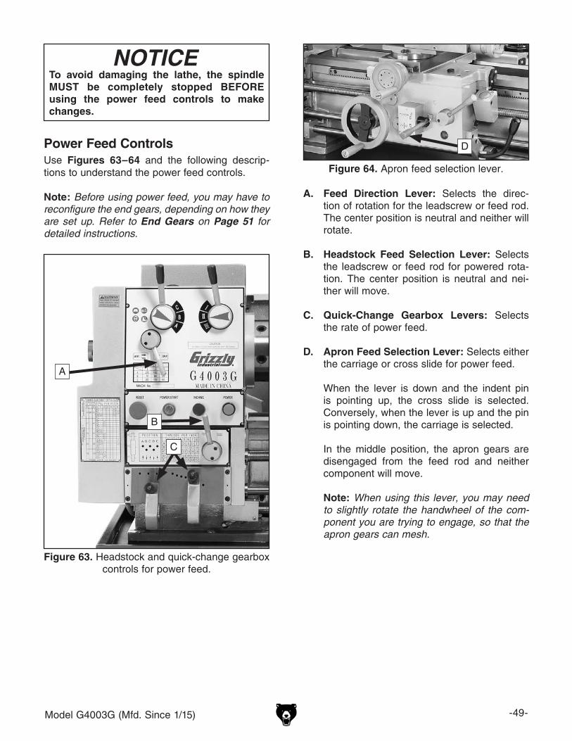
Model G4003G (Mfd. Since 1/15) -49-
To avoid damaging the lathe, the spindle MUST be completely stopped BEFORE using the power feed controls to make changes.
Power Feed ControlsUse Figures 63–64 and the following descrip-tions to understand the power feed controls.
Note: Before using power feed, you may have to reconfigure the end gears, depending on how they are set up. Refer to End Gears on Page 51 for detailed instructions.
Figure 64. Apron feed selection lever.
D
A. Feed Direction Lever: Selects the direc-tion of rotation for the leadscrew or feed rod. The center position is neutral and neither will rotate.
B. Headstock Feed Selection Lever: Selects the leadscrew or feed rod for powered rota-tion. The center position is neutral and nei-ther will move.
C. Quick-Change Gearbox Levers: Selects the rate of power feed.
D. Apron Feed Selection Lever: Selects either the carriage or cross slide for power feed.
When the lever is down and the indent pin is pointing up, the cross slide is selected. Conversely, when the lever is up and the pin is pointing down, the carriage is selected.
In the middle position, the apron gears are disengaged from the feed rod and neither component will move.
Note: When using this lever, you may need to slightly rotate the handwheel of the com-ponent you are trying to engage, so that the apron gears can mesh.
Figure 63. Headstock and quick-change gearbox controls for power feed.
A
B
C

-50- Model G4003G (Mfd. Since 1/15)
Setting Power Feed RateThe power feed rate chart in Figure 65 (also located on end gear cover) displays the end gear and quick-change gearbox lever settings for avail-able feed rates.
Figure 65. Feed rate chart.
This symbol indicates longitudinal feed.This symbol indicates cross feed rates.
Using the controls on the lathe, follow along with the example below to better understand how to set the lathe for the desired power feed rate.
Setting Cross Slide Power Feed Rate of 0.0021 in./rev.
1. Make sure end gears are set up as displayed on left side of chart (refer to End Gears on Page 51 for detailed instructions).
Note: The top half of the chart displays feed rates in mm/rev., while the bottom half dis-plays feed rates in in./rev.
2. Locate box in chart that lists a feed rate of 0.0021" in./rev. for cross slide (see Figure 66).
Figure 66. 0.0021 In./rev feed rate displayed in chart.
FeedRate
Setting for Gearbox Levers
NOTICETo prevent damage to gearbox components, NEVER move levers while lathe is running, and NEVER force any lever when shifting. If lever will not engage, rotate chuck by hand while keeping light pressure on lever. As chuck rotates it aligns gears and lever will engage.
3. Position lever pins in the gearbox holes indi-cated on chart.
— Pull knurled knob out which releases lever pin from hole.
— Lower lever below gearbox and slide it directly under desired hole.
— While pulling knurled knob out, raise lever so that pin is directly over hole, then release knob to seat pin (see Figure 67 for an example).
Figure 67. Example photo of gearbox lever pins seated in holes.

Model G4003G (Mfd. Since 1/15) -51-
4. Move headstock feed selection lever to left—this selects feed rod rotation.
5. Use headstock feed direction lever to select direction of cross feed travel.
When this lever is to right, cross slide will travel away from operator; conversely, when lever is to left, cross slide will travel toward operator.
6. Push apron feed selection lever toward spin-dle, then shift it down to select cross slide for power feed.
3. While holding middle 86T/91T gear assembly (see FIgure 69), loosen the support arm hex nut and slowly let assembly pivot down.
Support ArmHex Nut
Middle GearHex Nut
F Gear
G Gear
86T/91TGear
Figure 69. End gear components.
4. Remove middle gear, then F and G gears.
Note: Make sure the keys stay inserted in the shafts as you slide the F and G gears off.
5. Replace F and G gears with correct gears for operation as directed by charts.
Note: The 40T and 60T gear used as the G gear have a stepped face that allows the gear to mesh with either the outside or inside teeth of the middle gear, depending upon the configuration needed.
6. Secure F and G gears with fasteners, but do not overtighten. The fasteners merely keep them in place and overtightening may hinder rotation.
7. Slide middle gear against G gear until it meshes with a 0.002"–0.004" backlash, then tighten middle gear hex nut.
8. Pivot middle gear up against F gear until it meshes with same backlash, then tighten support arm hex nut.
9. Re-install end gear cover.
The end gears must be correctly setup for power feed, inch, or metric threading operations. Use Figure 68 to identify the upper F gear, middle 86T/91T change gears, and lower G gear, which are also referenced on the feed rate and thread-ing charts.
End Gears
Tools Needed QtyHex Wrench 3mm .............................................. 1Hex Wrench 5mm .............................................. 1Wrench or Socket 17mm ................................... 1
To change end gears:
1. DISCONNECT MACHINE FROM POWER!
2. Remove end gear cover.
Figure 68. End gear identification.
UpperF Gear
LowerG Gear
Middle86T/91T Gear

-52- Model G4003G (Mfd. Since 1/15)
Threading
The following subsections will describe how to use the threading controls and charts to set up the lathe for a threading operation. If you are unfamil-iar with the process of cutting threads on a lathe, we strongly recommend that you read books, review industry trade magazines, or get formal training before attempting any threading projects.
Headstock Threading ControlsThe threading charts on the headstock face dis-play the settings for inch and metric threading.
Using the controls on the lathe, follow the exam-ple below to understand how to set up the lathe for the desired threading operation.
To set up for a thread pitch of 13 TPI:
1. DISCONNECT MACHINE FROM POWER!
2. Install end gears as directed on inch thread chart (see Figure 70 or the chart on gear-box).
40T
40T
86T
Figure 70. End gear and gearbox lever configuration for 13 TPI.
End Gear Configuration
3. Position gearbox lever pins in gearbox holes indicated on chart—B and 7.
— Pull knurled knob out which releases lever pin from hole.
— Lower lever below gearbox and slide it directly under desired hole.
— While pulling knurled knob out, raise lever so that pin is directly over hole, then release knob to seat pin.
4. Move headstock feed selection to left for leadscrew rotation.
Apron Threading ControlsThe half nut lever engages the carriage with the leadscrew, which moves the carriage and cutting tool along the length of the workpiece for thread-ing operations (see Figure 71).
IMPORTANT: Make sure the feed selection lever is in the disengaged (center) position before attempting to engage the half nut.
Figure 71. Apron threading controls.
Cross SlideDisengaged
Feed SelectionLever
Carriage
Engaged
HalfnutLever
Disengaged
Feed SelectionLever
Half NutLever

Model G4003G (Mfd. Since 1/15) -53-
Thread Dial ChartThe thread dial chart is located on the headstock, as shown in Figure 73.
Thread DialTools Needed QtyHex Wrench 5mm .............................................. 1
The numbers on the thread dial are used with the thread dial chart to show when to engage the half nut during inch threading. Loosen the cap screw on the thread dial (see Figure 72), pivot the gear teeth so they mesh with the leadscrew threads, then retighten the cap screw.
IMPORTANT: The thread dial is not used for met-ric threading. You must leave the half nut engaged from the beginning until the threading is complete for metric threading.
When threading, we recommend using the slowest speed possible and avoiding deep cuts, so you are able to disengage the half nut when required and prevent an apron crash!
When the first thread cutting pass is complete, the operator disengages the carriage from the leadscrew using the half nut lever. The operator returns the carriage for the next pass and re-engages the half nut using the same thread dial setting to resume the cut as in the previous pass.
Figure 73. Location of thread dial chart.
Thread DialChart
Find the TPI (threads per inch) that you want to cut in the left columns (under T.P.I.), then refer-ence the dial number in the right columns (under Scale). The dial numbers indicate when to engage the half nut for a specific thread pitch as indicated by the thread dial chart (see Figure 74).
Figure 72. Thread dial engaged with the leadscrew.
ThreadDial
CapScrew
Figure 74. Thread dial chart.
TPI TPI TPISCALE SCALE SCALE
INDICATOR TABLE
4
4.5
4.75
5
5.5
6
6.5
7
8
9
9.5
10
11
12
13
14
16
18
19
20
22
24
26
28
32
36
38
40
44
48
52
56
64
72
76
80
88
96
104
112
1-2-3-4
1, 31–8
1–8
1–8
1–8
1–8
1–8
1–8
1–8
1–8
1–8
1–8
1–8
1–8
1–8
1–8
1–8
1–8
1–8
1–8
1–8
1–8
1–8
1
1
1
1
1
1, 3
1, 3
1, 3
1, 3
1, 3
1-2-3-4
1-2-3-4
1-2-3-4
1-2-3-4
1-2-3-4
1-2-3-4

-54- Model G4003G (Mfd. Since 1/15)
The following examples explain how to use the thread dial and the thread dial chart.
Even TPI: For threading an even number TPI, use any numbered line on the thread dial (see the example in Figure 75).
1
2
3
4
1
2
3
4
1
2
3
4
SCALE1–8
SCALE1
SCALE1, 3
1
2
3
4SCALEANY
1
2
3
4
SCALE
1-2-3-4
1–8&
Figure 75. Any numbered line on dial for threading even TPI.
1
2
3
4
1
2
3
4
1
2
3
4
12
3
4
SCALEALL
SCALEN
SCALE1
SCALE1, 3
1
2
3
4SCALEANY
Figure 76. 1 or 3 line on dial for threading odd TPI.
Odd TPI: For threading an odd number TPI, use the 1 or 3 line on the thread dial (see the example in Figure 76).
IMPORTANT: Once the 1 or 3 has been selected, continue using that same numbered line.
12
3
4
1
2
3
4
1
2
3
41
2
3
4
SCALEALL
SCALEN
SCALE1
SCALE1, 3
1
2
3
4SCALEANY
Figure 77. 1 line on dial for threading fractional TPI.
Fractional TPI: For threading a fractional TPI with a half number (4.5, 5.5, 6.5, 9.5), only use the 1 line on the thread dial (see the example in Figure 77).
IMPORTANT: For cutting 4.75 TPI, proceed as though cutting a metric thread and do not disen-gage the half nut until the threading operation is complete. Stop the spindle at the end of each cut, retract the cutting tool, and return the cutting tool to the start of the thread.
Note: For TPI divisible by 4, this rule still applies.The Indicator Table on the lathe shows that lines 1–8 may be used, which means that lines 1–4 and any of the half marks may be used.

Model G4003G (Mfd. Since 1/15) -55-
SECTION 5: ACCESSORIESACCESSORIES
order online at www.grizzly.com or call 1-800-523-4777
Figure 80. High-pressure oil cans for ball oilers.
H7616—Oil Can w/Plastic NozzleH7617—Oil Can w/Flexible Plastic NozzleThese high-pressure oil cans are perfect for lubri-cating the ball oilers found on your machine. Each can holds 5 ounces of oil.
H7616
H7617
T23964—Armor Plate with Moly-D Multi-Purpose Grease, 14.5 oz. (NLGI#2 Equivalent)Armor Plate with Moly-D is a rich green moly grease that provides excellent stability and unsur-passed performance under a wide range of tem-peratures and operating conditions. Armor Plate grease is entirely unique due to the fact that the moly in it is solubilized, which provides superior performance compared to other greases contain-ing the black solid form of molybdenum disulfide.
Figure 79. T23964 Armor Plate with Moly-D Multi-Purpose Grease.
G9856—6" 6-Jaw, High-Precision Run True Scroll ChuckA “Run True” is the best chuck you can buy. Every part is machined to precise tolerances and repeat-able concentricity is maintained. The unique micro-adjustment mounting feature enables repeatable accuracy to within 0.0005". Scroll and jaws are hardened and ground. Includes 2-piece jaws. This chuck features a semi-steel body and self-centering jaws. Requires Model T10347 6" back plate.
Figure 78. G9856 6" 6-Jaw "Run True" Scroll Chuck.
Installing unapproved accessories may cause machine to malfunction, resulting in serious personal injury or machine damage. To reduce this risk, only install accessories recommended for this machine by Grizzly.
NOTICERefer to our website or latest catalog for additional recommended accessories.

-56- Model G4003G (Mfd. Since 1/15)
order online at www.grizzly.com or call 1-800-523-4777
T10439—4-Pc. Carbide Insert CCMT Boring Bar SetThese right-hand indexable solid steel Boring Bars use 1⁄4" and 3⁄8", 80° diamond inserts and feature a negative 7° end and side cutting angle. Includes 3⁄8" x 6", 1⁄2" x 7", 5⁄8" x 8", and 3⁄4" x 10" boring bars. Set comes with Torx® wrenches and fitted aluminum case with handle.
Figure 81. T10439 Carbide Insert CCMT Boring Bar Set.
Quick-Change Tool HoldersAll models are Series 200G5701—Boring Bar Holder 3⁄4" G5704—Parting Tool Holder 5⁄8"G5705—Knurling Tool Holder 1⁄4" –5⁄8"G5703—Morse Taper Holder MT#3G5700—Turning/Boring Holder 1⁄4"~5⁄8"; 1⁄2"G5699—Turning Holders 1⁄4"~5⁄8"
Figure 82. Quick-change tool holders.
G5701 G5704 G5705
G5703 G5700 G5699
T24512—6-Piece HSS Center Drill SetHSS double-ended, 60° center drills are preci-sion-ground. Set includes:• 1 each of size #1, body diameter 1⁄8", drill
diameter 3⁄64", overall length 1 1⁄2"• 2 each of size #2, body diameter 3⁄16", drill
diameter 5⁄64", overall length 1 7⁄8"• 2 each of size #3, body diameter 1⁄4", drill
diameter 7⁄64", overall length 2"• 1 each of size #4, body diameter 5⁄16", drill
diameter 1⁄8", overall length 2 1⁄8"
Figure 84. T24512 6-Piece Center Drill Set.
T10414—5-C Quick-Change Collet Chuck D1-5This 5-C Quick Change Collet Chuck accepts all 5-C collets. Provides quick collet changes and concentricity of 0.0004". Fits D1-5 spindles.
G1238—15 pc. Precision 5-C Collet SetMade from high grade collet steel and precision ground to exacting tolerances. Complete 15 pc. set. Includes: 1⁄8" thru 1" in 1⁄16" increments.
Figure 83. 5-C quick-change collet chuck and 15 pc. 5-C collet set.
T10414
G1238

Model G4003G (Mfd. Since 1/15) -57-
order online at www.grizzly.com or call 1-800-523-4777
SBCE3450—How to Run a LatheFirst printed in 1907, this 56th edition is an exact reprint from 1966. Well illustrated with vintage photos and drawings, this 128-page book is writ-ten specifically about the care and operation of a metal lathe. "This book is to aid the beginner or apprentice in the machine shop and the student in the school shop to secure a better understand-ing of the fundamental operations of modern lathe practice in use in modern industries in the United States." Also available in Spanish.
T10719—Crown Savers for .17 to .45 Caliber Barrels (10 Pk.)T10720—Crown Savers for .50 Caliber Barrels (3 Pk.)With crown savers you never have to recrown the barrel when installing muzzle brakes or doing any job requiring a center in the end of the barrel crown.
Figure 89. T10720 Crown Savers.
Figure 88. SBCE3450 How to Run a Lathe.
T10667—Bald Eagle Reamer Holder MT#3Holder is designed to allow free movement of a floating reamer in 3 directions: vertical, horizontal, and angular, as required for proper performance of any floating reamer.
Figure 87. T10667 Bald Eagle Reamer Holder MT#3.
T10665—Adjustable Reamer Holder MT#3This Pacific Tool and Gauge Adjustable Reamer Holder secures a barrel chambering reamer in the holder for free floating reamer movement. A knurled wheel adjustment controls the amount of tension, which also limits free-floating movement.
Figure 86. T10665 PTG Reamer Holder MT#3.
T10295—7-Pc. Indexable Carbide Set 5/8"This 7-piece turning tool set is ideal for just about any project. Supplied with right-hand and left-hand turning tool holders, the set is complimented with one threading and cut-off tool too. Indexable inserts ensure cutting surfaces stay sharp.
Figure 85. T10295 17-Pc. Indexable Carbide Tool Set.

-58- Model G4003G (Mfd. Since 1/15)
order online at www.grizzly.com or call 1-800-523-4777
T10109—Gunsmith D-1 Back PlateThese D1-5 Back Plates have spiders machined into them, which allows shorter barrels to be sup-ported through the headstocks of larger lathes. (Guard removed for clarity.)
Figure 90. T10109 Gunsmith D1-5 Backplate.
Figure 93. H7991 Mini Mag Base Indicator Set.
H7991—Mini Mag Base Indicator SetSet features a 7 Jewel indicator with 0.0005" reso-lution. The mini magnetic base measures 13⁄16" x 13⁄16" x 13⁄8" and includes a single lock knob for easy set-ups. Includes 2 dovetail tool posts and a protective plastic case.
T10118—Tailstock Digital ReadoutHere’s the slickest setup for managing the depth of cut with your tailstock! Just set up, touch off and zero out! You’re going to know the exact position of the tool. Both the scale display and remote display come with a 0.0005" (five ten-thousandths of an inch) resolution, inch or millimeter display, zero keys and ON/OFF keys. The scale has an 8" range and its display features ABS or INC mode as well as a Hold key. Both displays read indepen-dently of each other, too! You’ll be able to see your depth at a glance with the large, 1⁄2" character remote display. The 6' data cable is long enough to mount the remote display in almost any conve-nient location. Tailstock adapter is not included, but can be shop made to fit your lathe.
Figure 91. H6095 Digital Readout.
H6095—Digital Readout (DRO)This is one of the finest two-axis DRO's on the market today. Features selectable resolution down to 5µm, absolute/incremental coordinate display, arc function, radius/diameter function, master reference datum, 199 machinist defined tools, double sealed scales, inches/millimeters and linear error compensation. Don't be fooled by our low prices—this is only a reflection of the absence of any “middlemen” in the marketing structure—not a reflection of the quality.
Figure 92. T10118 Tailstock Digital Readout.
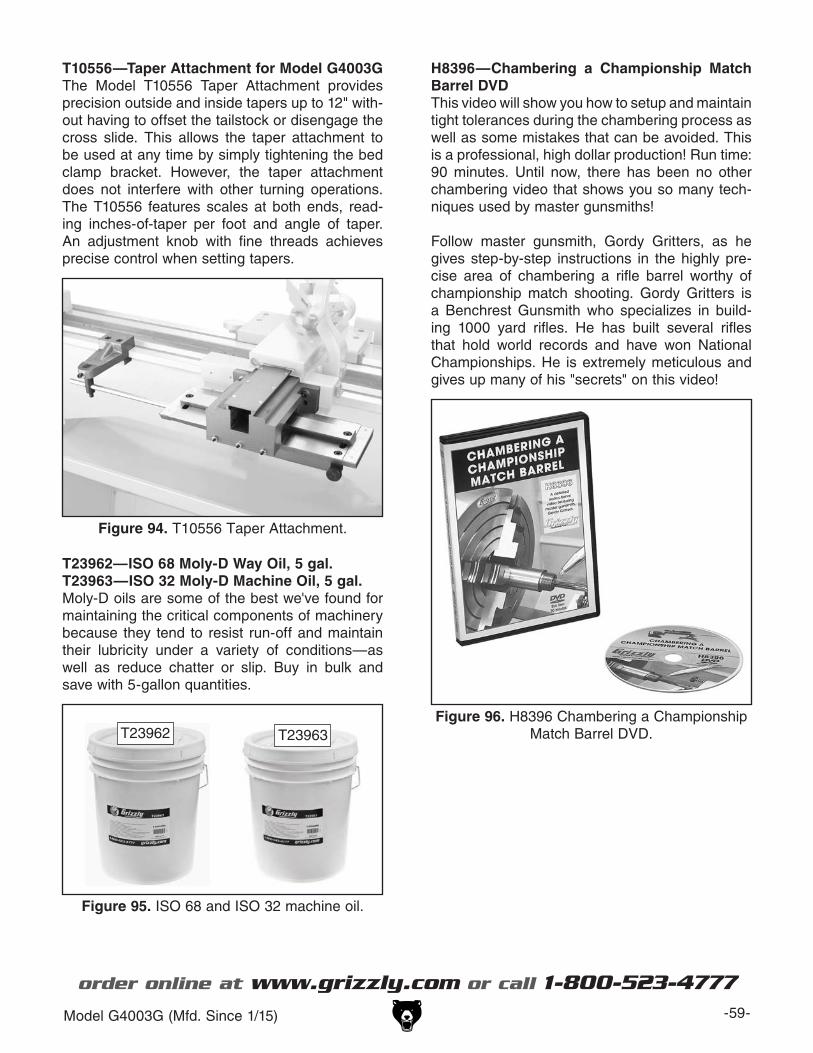
Model G4003G (Mfd. Since 1/15) -59-
T10556—Taper Attachment for Model G4003GThe Model T10556 Taper Attachment provides precision outside and inside tapers up to 12" with-out having to offset the tailstock or disengage the cross slide. This allows the taper attachment to be used at any time by simply tightening the bed clamp bracket. However, the taper attachment does not interfere with other turning operations. The T10556 features scales at both ends, read-ing inches-of-taper per foot and angle of taper. An adjustment knob with fine threads achieves precise control when setting tapers.
Figure 94. T10556 Taper Attachment.
H8396—Chambering a Championship Match Barrel DVDThis video will show you how to setup and maintain tight tolerances during the chambering process as well as some mistakes that can be avoided. This is a professional, high dollar production! Run time: 90 minutes. Until now, there has been no other chambering video that shows you so many tech-niques used by master gunsmiths!
Follow master gunsmith, Gordy Gritters, as he gives step-by-step instructions in the highly pre-cise area of chambering a rifle barrel worthy of championship match shooting. Gordy Gritters is a Benchrest Gunsmith who specializes in build-ing 1000 yard rifles. He has built several rifles that hold world records and have won National Championships. He is extremely meticulous and gives up many of his "secrets" on this video!
Figure 96. H8396 Chambering a Championship Match Barrel DVD.
T23962—ISO 68 Moly-D Way Oil, 5 gal.T23963—ISO 32 Moly-D Machine Oil, 5 gal.Moly-D oils are some of the best we've found for maintaining the critical components of machinery because they tend to resist run-off and maintain their lubricity under a variety of conditions—as well as reduce chatter or slip. Buy in bulk and save with 5-gallon quantities.
Figure 95. ISO 68 and ISO 32 machine oil.
T23962 T23963
order online at www.grizzly.com or call 1-800-523-4777

-60- Model G4003G (Mfd. Since 1/15)
SECTION 6: MAINTENANCE
Schedule
To reduce risk of shock or accidental startup, always disconnect machine from power before adjustments, maintenance, or service.
OngoingTo maintain a low risk of injury and proper machine operation, if you ever observe any of the items below, shut down the machine immediately and fix the problem before continuing operations:
• Loose mounting bolts or fasteners.• Worn, frayed, cracked, or damaged wires.• Guards or covers removed.• Emergency Stop/RESET button not working
correctly or not requiring you to reset it before starting the machine again.
• Oil level not visible in the sight glasses.• Damaged or malfunctioning components.
Daily, Before Operations• Check/add headstock oil (Page 61).• Add quick-change gearbox oil (Page 633).• Check/add apron oil (Page 63).• Lubricate the bedways (Page 644).• Add oil to the ball oilers (Page 64).• Clean/lubricate the leadscrew (Page 63).• Check/retension V-belts (Page 73).• Disengage the apron feed selection lever (to
prevent crashes upon startup).• Ensure carriage lock bolt is loose.
Daily, After Operations• Press the Emergency Stop/RESET button (to
prevent accidental startup).• Vacuum/clean all chips and swarf from bed,
slides.• Wipe down all unpainted or machined sur-
faces with an oiled rag.
Semi-Annually• Change the headstock oil (Page 62).
Annually• Change the apron oil (Page 63).• Lubricate end gears (Page 65).• Check/level bedway (Page 22).
Cleaning/Protecting
Because of its importance, we recommend that the cleaning routine be planned into the workflow schedule.
Typically, the easiest way to clean swarf from the machine is to use a wet/dry shop vacuum that is dedicated for this purpose. The small chips left over after vacuuming can be wiped up with a slightly oiled rag. Avoid using compressed air to blow off chips, as this may drive them deeper into the moving surfaces or cause sharp chips to fly into your face or hands.
All unpainted and machined surfaces should be wiped down daily to keep them rust free and in top condition. This includes any surface that is vulnerable to rust if left unprotected (especially parts that are exposed to water-soluble cutting fluid). Use way oil to prevent corrosion (see Page 60 for an offering from Grizzly).

Model G4003G (Mfd. Since 1/15) -61-
Lubrication
Use the information in the charts below as a daily guide for lubrication tasks. We recommend using Grizzly Model T23962, T23963, or T23964 lubricants (see Pages 55 and 60) for most of the lubrication tasks.
NOTICEThe recommended lubrication is based on light-to-medium usage. Keeping in mind that lubrication helps to protect the value and operation of the lathe, these lubrication tasks may need to be performed more fre-quently than recommended here, depend-ing on usage.
Failure to follow reasonable lubrication practices as instructed in this manual could lead to premature failure of lathe compo-nents and will void the warranty.
HeadstockOil Type .... Grizzly T23963 or ISO 32 Equivalent Oil Amount .......................................... 3.5 QuartsCheck/Add Frequency ................................. DailyChange Frequency ....................... Semi-Annually
The headstock gearing is lubricated by an oil bath that distributes the lubricant with the motion of the gears, much like an automotive manual transmis-sion. Change the oil after the first 2 hours of use, then semi-annually.
Checking Oil LevelThe headstock reservoir has the proper amount of oil when the oil level in the sight glass is approxi-mately halfway. The oil sight glass is located below the chuck, as shown in Figure 97.
Figure 97. Location of headstock oil sight glass.
HeadstockOil Sight Glass

-62- Model G4003G (Mfd. Since 1/15)
Adding OilThe oil fill plug is located on top of the headstock, as shown in Figure 98.
Figure 98. Locations of headstock fill and drain plugs.
Fill Plug
DrainPlug
To change headstock oil:
1. DISCONNECT MACHINE FROM POWER!
2. Remove end gear cover.
3. Remove V-belts so that oil does not get on them, necessitating their replacement (refer to the V-Belt Tension & Replacement on Page 73 for detailed instructions).
4. Remove fill plug to allow oil to drain more freely.
5. Place a funnel and a 2-gallon catch pan under drain plug, then use 8mm hex wrench to remove drain plug.
6. When headstock reservoir is empty, replace drain plug and clean away any spilled oil.
7. Fill headstock reservoir until oil level is approximately halfway in sight glass, then replace fill plug.
8. Replace and retension V-belts, then secure end-gear cover before reconnecting lathe to power.
Quick-Change GearboxOil Type .... Grizzly T23962 or ISO 68 EquivalentOil Amount ............................2 Pumps Each PortCheck/Add Frequency ................................. Daily
The quick-change gearbox uses a drip-type lubri-cation through two ports on the right side of the gearbox (see Figure 99).
Figure 99. Locations of gearbox oil ports.
GearboxLubrication
Ports
Use a pump-type oil can to add two pumps to each oil port, then wipe away any spilled oil.

Model G4003G (Mfd. Since 1/15) -63-
ApronOil Type .... Grizzly T23962 or ISO 68 EquivalentOil Amount .......................................... 0.5 QuartsCheck/Add Frequency ................................. DailyChange Frequency ................................ Annually
Checking Oil LevelThe apron oil sight glass is on the front of the apron, as shown in Figure 100. Maintain the oil volume so that the level is approximately halfway in the sight glass.
BedwaysOil Type .... Grizzly T23962 or ISO 68 EquivalentOil Amount ......................................... As NeededLubrication Frequency ................................. Daily
Before lubricating the bedways (see Figure 102), clean them with mineral spirits. Apply a thin coat of oil along the length of the bedway. Move the steady rest, carriage, and tailstock to access the entire length of the bedways. If the lathe is in a moist or dirty environment, increase the lubrica-tion interval.
Changing Oil & Flushing ReservoirSmall metal particles may accumulate at the bot-tom of the reservoir with normal use. Therefore, to keep the reservoir clean, drain and flush it at least once a year.
Place a catch pan under the apron drain plug shown in Figure 101, remove the fill plug, then use a 6mm hex wrench to remove the drain plug and empty the reservoir.
Flush the reservoir by pouring a small amount of clean oil into the fill hole and allowing it to drain out the bottom. Replace the drain plug, add oil as previously described, then re-install the fill plug.
Figure 100. Location of apron oil sight glass.
Fill Plug
SightGlass
Longitudinal LeadscrewOil Type .... Grizzly T23962 or ISO 68 EquivalentOil Amount ......................................... As NeededLubrication Frequency ................................. Daily
Before lubricating the leadscrew (see Figure 102), clean it first with mineral spirits. A stiff brush works well to help clean out the threads. Make sure to move the carriage out of the way, so you can clean the entire length of the leadscrew.
Apply a thin coat of oil along the length of the leadscrew. Use a stiff brush to make sure the oil is applied evenly and down into the threads.
Note: In some environments, abrasive material can become caught in the leadscrew lubricant and drawn into the half nut. In this case, lubricate the leadscrew with a quality dry lubricant.
Figure 102. Bedways.
Bedways
Leadscrew
Figure 101. Location of apron drain plug.
Drain Plug

-64- Model G4003G (Mfd. Since 1/15)
Ball OilersOil Type .... Grizzly T23963 or ISO 32 EquivalentOil Amount ......................................1 or 2 SquirtsLubrication Frequency ................................. Daily
This lathe has 14 ball oilers that should be oiled on a daily basis before beginning operation. Refer to Figures 103–1056 for their locations.
Ball OilersProper lubrication of ball oilers is done with a pump-type oil can that has a plastic or rubberized cone tip (see Page 55 for offerings from Grizzly). We do not recommend using metal needle or lance tips, as they can push the ball too far into the oiler, break the spring seat, and lodge the ball in the oil galley.
Lubricate the ball oilers before and after machine use, and more frequently under heavy use. When lubricating ball oilers, first clean the outside sur-face to remove any dust or grime. Push the rub-ber or plastic tip of the oil can nozzle against the ball oiler to create a hydraulic seal, then pump the oil can once or twice. If you see sludge and con-taminants coming out of the lubrication area, keep pumping the oil can until the oil runs clear. When finished, wipe away any excess oil.
A. Compound-rest leadscrew & slidesB. Cross-slide leadscrew & slidesC. Saddle slidesD. Carriage handwheelE. Tailstock ball oilersF. Leadscrew end bearingG. Feed rod end bearing
Figure 103. Saddle and slide ball oilers.
A
BC
Figure 104. Carriage handwheel ball oiler.
D
Figure 105. Tailstock ball oilers.
E
Figure 106. Leadscrew & feed rod ball oilers.
G
F

Model G4003G (Mfd. Since 1/15) -65-
End GearsGrease ..... Grizzly T23964 or NLGI#2 EquivalentFrequency ............... Annually or When Changing
The end gears, shown in Figure 107, should always have a thin coat of heavy grease to minimize corrosion, noise, and wear. Wipe away excess grease that could be thrown onto the V-belts and reduce optimal power transmission from the motor.
Figure 107. End gears.
Handling & CareMake sure to clean and lubricate any gears you install or change. Be very careful during handling and storage—the grease coating on the gears will easily pickup dirt or debris, which can then spread to the other gears and increase the rate of wear.
Make sure the end gear cover remains installed whenever possible to keep the gears free of dust or debris from the outside environment.
Lubricating1. DISCONNECT LATHE FROM POWER!
2. Remove end gear cover and all end gears shown in Figure 107.
3. Clean end gears thoroughly with mineral spir-its to remove old grease. Use a small brush if necessary to clean between teeth.
4. Clean shafts, and wipe away any grease splatters in vicinity and on inside of end gear cover.
5. Using a clean brush, apply a thin layer of grease on gears. Make sure to get grease between gear teeth, but do not fill teeth val-leys.
6. Install end gears and mesh them together with an approximate 0.002"–0.004" backlash. Once gears are meshed together, apply small dab of grease between them where they mesh together—this grease will be dis-tributed when gears rotate and recoat any areas scraped off during installation.
7. Re-install end gear cover before reconnect-ing lathe to power.
Lubrication Port

-66- Model G4003G (Mfd. Since 1/15)
To prevent the development of rust and corrosion, the lathe must be properly prepared if it will be stored for a long period of time. Doing this will ensure the lathe remains in good condition for later use.
Preparing Lathe for Storage1. Run lathe and bring headstock and apron
reservoirs to operating temperature, then drain and refill them with clean oil.
2. DISCONNECT LATHE FROM POWER!
3. Thoroughly clean all unpainted, bare metal surfaces, then apply a liberal coat of way oil, heavy grease, or rust preventative. Take care to ensure these surfaces are completely covered but that rust preventative or grease is kept off of painted surfaces.
4. Lubricate machine as outlined in Lubrication section beginning on Page 61. Be sure to use an oil can to purge all ball oilers and oil pas-sages with fresh oil.
5. Loosen or remove V-belts so they do not become stretched during storage period. (Be sure to place a maintenance note near power button as a reminder that the belts have been loosened or removed.)
Machine Storage 6. Place a few moisture absorbing desiccant packs inside of electrical box.
7. Cover lathe and place it in a dry area that is out of direct sunlight and away from hazard-ous fumes, paint, solvents, or gas. Fumes and sunlight can bleach or discolor paint.
8. Every few months, rotate by hand all gear-driven components a few times in several gear selections. This will keep the bearings, bushings, gears, and shafts well lubricated and protected from corrosion—especially during the winter months.
Slide carriage, tailstock, and steady rest down lathe bed to make sure that way spot-ting is not beginning to occur.
Bringing Lathe Out of Storage1. Re-install V-belts and retension them (refer
to Page 73 for detailed instructions) if you removed them for storage purposes.
2. Remove moisture absorbing desiccant packs from electrical box.
3. Repeat Test Run and Spindle Break-In pro-cedures, beginning on Page 25.

Model G4003G (Mfd. Since 1/15) -67-
Review the troubleshooting and procedures in this section if a problem develops with your machine. If you need replacement parts or additional help with a procedure, call our Technical Support. Note: Please gather the serial number and manufacture date of your machine before calling.
SECTION 7: SERVICE
Troubleshooting
Motor & ElectricalSymptom Possible Cause Possible SolutionMachine does not start or a circuit breaker trips.
1. Emergency Stop\RESET button engaged or at fault.
2. Fuse has blown in machine electrical box.
3. Power supply switched OFF or at fault.4. Motor/plug wired incorrectly.
5. Thermal overload relay has tripped.
6. Wall fuse/circuit breaker is blown/tripped; short in electrical system; start-up load too high for circuit.
7. Start capacitor at fault. 8. Contactor not getting energized/has burned
contacts.9. Wiring is open/has high resistance.
10. Motor is at fault.
1. Rotate button clockwise until it pops out to reset it for operation; replace if not working properly.
2. Replace fuse/ensure no; determine if overload is due to heavy operation; ensure power source has high enough voltage and power cord is correctly sized.
3. Ensure power supply is ON/has correct voltage.4. Correct motor/plug wiring connections (Pages 82
and 84).5. Turn the thermal relay cut-out dial to increase
working amps and push the reset pin. Replace if tripped multiple times (weak relay).
6. Verify circuit is rated for machine amp load; troubleshoot and repair cause of overload; replace weak breaker; find/repair electrical short.
7. Test/replace if faulty.8. Test for power on all legs and contactor operation.
Replace unit if faulty.9. Check for broken wires or disconnected/corroded
connections, and repair/replace as necessary. 10. Test/repair/replace.
Motor stalls or is underpowered.
1. V-belt(s) slipping.
2. Run capacitor at fault.3. Plug/receptacle at fault.4. Gearbox at fault.
5. Contactor not energized/has poor contacts.6. Motor bearings at fault.7. Motor at fault.
1. Tension/replace V-belt(s) (Page 73); ensure pulleys are aligned.
2. Test/repair/replace.3. Test for good contacts/correct wiring.4. Select appropriate gear ratio; replace broken or
slipping gears.5. Test all legs for power/replace if faulty.6. Test/repair/replace.7. Test/repair/replace.
Loud, repetitious noise coming from lathe at or near the motor.
1. Pulley set screws or keys are missing or loose.
2. Motor fan is hitting the cover.
1. Inspect keys and set screws. Replace or tighten if necessary.
2. Tighten fan, shim cover, or replace items.
Motor overheats. 1. Motor overloaded. 1. Allow motor to cool; reduce load on motor.
Motor is loud when cutting, or bogs down under load.
1. Excessive depth of cut or feed rate.2. Spindle speed or feed rate wrong for
cutting operation.3. Cutting tool is dull.
1. Decrease depth of cut or feed rate.2. Refer to feed/speed charts in Machinery's
Handbook or feed/speed calculator on the internet.3. Sharpen or replace the cutting tool.

-68- Model G4003G (Mfd. Since 1/15)
Lathe OperationSymptom Possible Cause Possible SolutionEntire machine vibrates upon startup and while running.
1. Workpiece is unbalanced.
2. Loose or damaged V-belt(s).
3. V-belt pulleys are not properly aligned.4. Worn or broken gear present.5. Chuck or faceplate is unbalanced.
6. Gears not aligned in headstock or no backlash.
7. Broken gear or bad bearing.8. Workpiece is hitting stationary object.
9. Spindle bearings at fault.
1. Re-install workpiece as centered with the spindle bore as possible.
2. Retension/replace the V-belt(s) as necessary (see Page 73).
3. Align the V-belt pulleys.4. Inspect gears, and replace if necessary.5. Rebalance chuck or faceplate; contact a local
machine shop for help.6. Adjust change gears and establish backlash.
7. Replace broken gear or bearing.8. Stop lathe immediately and correct interference
problem.9. Reset spindle bearing preload (Page 75) or replace
worn spindle bearings.
Bad surface finish. 1. Wrong spindle speed or feed rate.2. Dull tooling or poor tool selection.
3. Tool height not at spindle centerline.
4. Too much play in gibs.
1. Adjust for appropriate spindle speed and feed rate.2. Sharpen tooling or select a better tool for the
intended operation.3. Adjust tool height to spindle centerline (see Page
37).4. Tighten gibs (see Page 71).
Tapered tool difficult to remove from tailstock quill.
1. Quill is not retracted all the way back into the tailstock.
2. Contaminants not removed from taper before inserting into quill.
1. Turn the quill handwheel until it forces the tapered tool out of quill.
2. Clean the taper and bore, then re-install tool.
Cross slide, compound rest, or carriage feed has sloppy operation.
1. Gibs are out of adjustment.2. Handwheel is loose or backlash is high.
3. Leadscrew mechanism worn.
1. Adjust gibs (see Page 71).2. Tighten handwheel fasteners, adjust hanhdwheel
backlash to a minimum (see Page 70).3. Replace leadscrew mechanism.
Cross slide, compound, or carriage handwheels hard to move.
1. Dovetail ways loaded with shavings, dust, or grime.
2. Gib screws are too tight.
3. Backlash setting too tight.4. Bedways are dry.
1. Remove gibs, clean ways, lubricate, and re-adjust gibs.
2. Loosen gib screw(s) slightly (see Page 71), and lubricate bedways.
3. Slightly loosen backlash setting (see Page 70).4. Lubricate bedways/ball oilers (Page 63).
Cutting tool or machine components vibrate excessively during cutting.
1. Tool holder not tight enough.2. Cutting tool sticks too far out of tool holder;
lack of support.3. Gibs are out of adjustment.4. Dull cutting tool.5. Incorrect spindle speed or feed rate.
1. Check for debris, clean, and retighten.2. Re-install cutting tool so no more than 1⁄3 of the total
length is sticking out of tool holder.3. Adjust gibs (see Page 71).4. Replace or resharpen cutting tool.5. Use the recommended spindle speed and feed rate.

Model G4003G (Mfd. Since 1/15) -69-
Symptom Possible Cause Possible SolutionWorkpiece is tapered.
1. Headstock and tailstock are not properly aligned with each other.
1. Re-align the tailstock to the headstock spindle centerline (see Page 37).
Chuck jaws will not move or do not move easily.
1. Chips lodged in the jaws or scroll plate. 1. Remove jaws, clean and lubricate scroll plate, then replace jaws.
Carriage will not feed or is hard to move.
1. Gears are not all engaged.2. Half nut lever engaged.3. Loose screw on the feed handle.4. Carriage lock is tightened down.
5. Chips have loaded up on bedways.
6. Bedways are dry and in need of lubrication. 7. Gibs are too tight.8. Gears broken.
1. Adjust gear levers.2. Disengage half nut lever.3. Tighten.4. Check to make sure the carriage lock bolt is fully
released.5. Frequently clean away chips that load up during
turning operations.6. Lubricate bedways/ball oilers.7. Loosen gibs screw(s) slightly (see Page 71).8. Replace gears.
Gear change levers will not shift into position.
1. Gears not aligned inside headstock/quick-change gearbox.
1. Rotate spindle by hand with light pressure on the lever until gear falls into place.
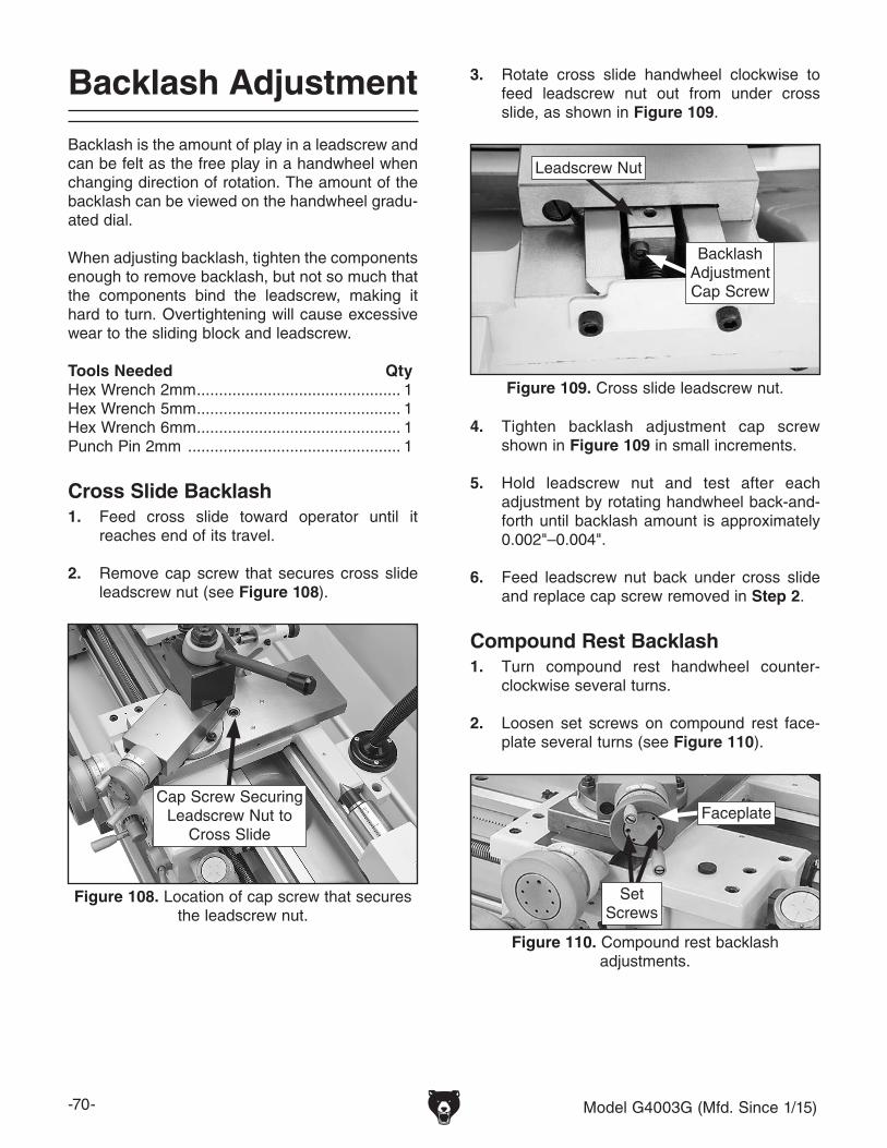
-70- Model G4003G (Mfd. Since 1/15)
Backlash Adjustment
Backlash is the amount of play in a leadscrew and can be felt as the free play in a handwheel when changing direction of rotation. The amount of the backlash can be viewed on the handwheel gradu-ated dial.
When adjusting backlash, tighten the components enough to remove backlash, but not so much that the components bind the leadscrew, making it hard to turn. Overtightening will cause excessive wear to the sliding block and leadscrew.
Tools Needed QtyHex Wrench 2mm .............................................. 1Hex Wrench 5mm .............................................. 1Hex Wrench 6mm .............................................. 1Punch Pin 2mm ................................................ 1
Cross Slide Backlash1. Feed cross slide toward operator until it
reaches end of its travel.
2. Remove cap screw that secures cross slide leadscrew nut (see Figure 108).
3. Rotate cross slide handwheel clockwise to feed leadscrew nut out from under cross slide, as shown in Figure 109.
Figure 108. Location of cap screw that secures the leadscrew nut.
Cap Screw Securing Leadscrew Nut to
Cross Slide
4. Tighten backlash adjustment cap screw shown in Figure 109 in small increments.
5. Hold leadscrew nut and test after each adjustment by rotating handwheel back-and-forth until backlash amount is approximately 0.002"–0.004".
6. Feed leadscrew nut back under cross slide and replace cap screw removed in Step 2.
Compound Rest Backlash1. Turn compound rest handwheel counter-
clockwise several turns.
2. Loosen set screws on compound rest face-plate several turns (see Figure 110).
Figure 109. Cross slide leadscrew nut.
Leadscrew Nut
Backlash Adjustment Cap Screw
Figure 110. Compound rest backlash adjustments.
Set Screws
Faceplate

Model G4003G (Mfd. Since 1/15) -71-
3. Use punch pin to loosen faceplate and adjust it until backlash is approximately 0.002"–0.004", as indicated on graduated dial.
4. Secure setting with set screws.
5. Repeat adjustments above if necessary.
The goal of adjusting the gib screws is to remove sloppiness or "play" from the ways without over-adjusting them to the point where they become stiff and difficult to move.
In general, loose gibs cause poor finishes and tool chatter; however, over-tightened gibs cause premature wear and make it difficult to turn the handwheels.
The cross-slide and compound slide on this lathe each use a long steel wedge called a gib that is positioned between the component and its dove-tailed-ways. At the end of each gib is a gib screw, which moves and holds the gib. Depending upon which direction the gib moves, the space between the sliding ways increases or decreases to control the rigidity of the cross slide and compound slide.
Before adjusting the gibs, loosen the locks for the device so that the gibs can freely slide during adjustment, then lubricate the ways.
The gib adjustment process usually requires some trial-and-error. Repeat the adjustment pro-cess as necessary until you find the best balance between loose and stiff movement. Most machin-ists find that the ideal gib adjustment is one where a small amount of drag or resistance is present, yet the handwheels are still easy to move.
Gib Adjustment
Tools Needed QtyStandard Screwdriver #2 ................................... 1Hex Wrench 3mm .............................................. 1Hex Wrench 6mm .............................................. 1Wrench 10mm ................................................... 1
Make sure the bedways and leadscrew have been cleaned and relubricated before beginning any adjustments. Refer to Lubrication beginning on Page 61 for instructions and lubricant specifica-tions.
Cross Slide Gib1. DISCONNECT LATHE FROM POWER!
2. Loosen locking set screw shown in Figure 111.
3. Adjust gib screws as follows:
— To increase slide tension, loosen rear gib screw 1⁄8 turn, and tighten front gib screw 1⁄8 turn.
—To decrease slide tension, loosen front gib screw 1⁄8 turn, and tighten rear gib screw 1⁄8 turn.
4. After each adjustment, use cross slide handwheel to test cross slide movement.
5. Repeat Steps 3–4 until cross slide move-ment is acceptable.
Figure 111. Cross slide gib components.
Set Screw
Gib Screw(1 of 2)

-72- Model G4003G (Mfd. Since 1/15)
Saddle GibBefore making adjustments to the saddle gib, make sure that the carriage lock (see Figure 113) is loose by turning it counterclockwise one full turn.
Compound Rest GibFigure 112 shows the gib location on the com-pound rest. The compound rest gib adjusts in the same manner and with the same tools as the cross slide gib. However, in this case, to increase or decrease tension, the gib adjustment screw directions are reversed.
Figure 113. Location of carriage lock.
Carriage Lock
The saddle gib is located on the bottom of the back edge of the slide (see Figure 114). This gib is designed differently than the cross or compound slide gibs. Instead of being a wedge-shaped plate, it is a flat bar. The gib pressure is applied by four set screws. Hex nuts secure these set screws in place, so they will not loosen during operation.
To adjust saddle slide gib:
1. DISCONNECT LATHE FROM POWER!
2. Loosen jam nuts on four set screws shown in Figure 114, and adjust set screws same amount as follows:
—To tighten carriage gib, tighten set screws.
—To loosen gib, loosen set screws.
3. Move carriage back and forth and repeat adjustments as necessary until gib pressure is acceptable.
4. Hold set screws in place and tighten jam nuts.
Figure 112. Compound rest gib components.
Set Screw
Gib Screw(1 of 2)
Figure 114. Saddle gib components(viewed from rear of saddle).
Set Screws

Model G4003G (Mfd. Since 1/15) -73-
Half Nut Adjustment
The half-nut mechanism can be adjusted if it becomes loose from wear. The half nut is mount-ed in ways with a gib exerting pressure between the components to reduce sloppy movement. The half-nut gib is a flat bar-type gib, similar to the saddle gib, and is tensioned with two set screws.
Tools Needed QtyHex Wrench 4mm .............................................. 1Hex Wrench 5mm .............................................. 1Wrench 13mm ................................................... 1
To adjust half nut:
1. DISCONNECT MACHINE FROM POWER!
2. Disengage half nut and remove thread dial.
3. Loosen hex nuts on set screws shown in Figure 115.
4. Tighten each set screw approximately 1⁄8 of a turn, then retighten the hex nuts without mov-ing the set screws.
5. Move carriage handwheel until half nut can fully close, then open/close half nut several times and notice how it feels. The half nut is correctly adjusted when you feel a slight drag while opening and closing it. It should not feel too stiff or too loose.
6. Repeat Steps 3–5, if necessary, until you are satisfied with half nut adjustment, then re-install thread dial.
Figure 115. Half nut gib set screws.
Set Screws
Half Nut
After initial break in, the V-belts stretch slightly and seat into the pulley. It is important to check and adjust them to compensate for this initial wear. Check the tension thereafter on a monthly basis. If the belts become excessively worn or damaged, replace them as a matched set.
Tools Needed QtyHex Wrench 17mm ............................................ 1
Tensioning V-Belts1. DISCONNECT MACHINE FROM POWER!
2. Remove end gear cover.
3. Loosen motor mount hex bolts (see Figure 116).
Note: It may be more convenient to access the motor mount hex nuts if you first remove the rear splash guard.
V-Belt Tension & Replacement
Figure 116. Locations of motor mount hex bolts.
Motor MountHex Bolts

-74- Model G4003G (Mfd. Since 1/15)
5. When V-belt tension is correct, retighten motor mount hex bolts.
6. Secure end gear cover.
Replacing V-Belts1. DISCONNECT MACHINE FROM POWER!
2. Remove end gear cover.
3. Loosen motor mount bolts (see Figure 116 on the previous page), slide motor up, and remove V-belts.
Note: It may be more convenient to access the motor mount bolts if you first remove the rear splash guard.
4. Install new V-belts as a matched set so they equally share the load.
5. Tension belts (refer to Tensioning V-Belts on the previous page.)
6. Secure end gear cover.
PulleyDeflection
Pulley
Figure 117. Correct timing-belt deflection.
1⁄4"
4. Push down on motor until there is approxi-mately 1⁄4" deflection in V-belts when moder-ate pressure is applied between pulleys, as shown in Figure 117.
Gap Removal & Installation
This lathe is equipped with a removable gap insert that will allow for turning large diameter workpieces. The gap was seated, preloaded, and then ground for precise bedway mating and align-ment at the factory.
Removing the gap can cause the lathe insert to slightly spring out of shape. When re-installed, there is no guarantee that original alignment and flush mating will be the same. For this reason, removing the gap is considered a permanent alteration to the lathe, even if it is later re-installed.
Tools Needed QtyOpen End Wrench 14mm .................................. 1Hex Wrench 8mm .............................................. 1Heavy Dead Blow Hammer ............................... 1Miscellaneous C-Clamps ................ As RequiredWooden Blocks ............................... As Required
To remove gap:
1. DISCONNECT LATHE FROM POWER!
2. Remove four cap screws that secure gap to bed (see Figure 118).
3. Tighten alignment pin hex nuts (see Figure 118) to draw pins from gap.
Figure 118. Gap retaining fasteners.
Preload Cap Screw
CapScrews(2 of 4)Alignment
Pins &Hex Nut(1 of 2)
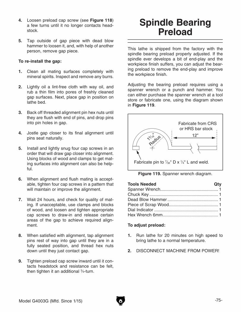
Model G4003G (Mfd. Since 1/15) -75-
4. Loosen preload cap screw (see Figure 118) a few turns until it no longer contacts head-stock.
5. Tap outside of gap piece with dead blow hammer to loosen it, and, with help of another person, remove gap piece.
To re-install the gap:
1. Clean all mating surfaces completely with mineral spirits. Inspect and remove any burrs.
2. Lightly oil a lint-free cloth with way oil, and rub a thin film into pores of freshly cleaned gap surfaces. Next, place gap in position on lathe bed.
3. Back off threaded alignment pin hex nuts until they are flush with end of pins, and drop pins into pin holes in gap.
4. Jostle gap closer to its final alignment until pins seat naturally.
5. Install and lightly snug four cap screws in an order that will draw gap closer into alignment. Using blocks of wood and clamps to get mat-ing surfaces into alignment can also be help-ful.
6. When alignment and flush mating is accept-able, tighten four cap screws in a pattern that will maintain or improve the alignment.
7. Wait 24 hours, and check for quality of mat-ing. If unacceptable, use clamps and blocks of wood, and loosen and tighten appropriate cap screws to draw-in and release certain areas of the gap to achieve required align-ment.
8. When satisfied with alignment, tap alignment pins rest of way into gap until they are in a fully seated position, and thread hex nuts down until they just contact gap.
9. Tighten preload cap screw inward until it con-tacts headstock and resistance can be felt, then tighten it an additional 3⁄4-turn.
Fabricate pin to 7⁄32" D x 1⁄4" L and weld.
19 ⁄16"
Radius 12"
Fabricate from CRS or HRS bar stock
Figure 119. Spanner wrench diagram.
Spindle Bearing Preload
This lathe is shipped from the factory with the spindle bearing preload properly adjusted. If the spindle ever develops a bit of end-play and the workpiece finish suffers, you can adjust the bear-ing preload to remove the end-play and improve the workpiece finish.
Adjusting the bearing preload requires using a spanner wrench or a punch and hammer. You can either purchase the spanner wrench at a tool store or fabricate one, using the diagram shown in Figure 119.
Tools Needed QtySpanner Wrench................................................ 1Chuck Key ......................................................... 1Dead Blow Hammer .......................................... 1Piece of Scrap Wood......................................... 1Dial Indicator ..................................................... 1Hex Wrench 6mm .............................................. 1
To adjust preload:
1. Run lathe for 20 minutes on high speed to bring lathe to a normal temperature.
2. DISCONNECT MACHINE FROM POWER!

-76- Model G4003G (Mfd. Since 1/15)
4. Remove end gear cover, then removethe outboard spindle cover (see Figure 121).
C
B
A
I
II
III
Alpha Lever
Set between B & C
Numeric Lever
Set between I & II
Figure 120. Spindle speed levers set to neutral.
5. Place chuck key in cam-lock socket and keep spindle from rotating.
6. Using a spanner wrench, or hammer-and-punch, loosen outer spanner nut (Figure 122) counterclockwise and remove it.
3. Remove chuck, then shift spindle to neutral by positioning alpha spindle speed lever between C and B and numeric spindle speed lever between the I and II, as shown in Figure 120.
Figure 121. Outboard spindle cover.
OutboardSpindleCover
Figure 122. Loosening outer spanner nut.
Outer Spanner Nut
SpannerWrench
9. Place dial indicator on cross slide and move carriage toward headstock until contact point of indicator touches spindle face, as shown in Figure 124.
Figure 124. Dial indicator setup.
7. Loosen inner spanner nut one turn.
Note: You may have to tap on the outboard end of the spindle as explained in Step 8, to help unload the spindle and break the span-ner nut loose.
8. Place wooden block over outboard end of spindle, tap it a few times with small sledge or heavy dead blow hammer (Figure 123). Your goal is to slide spindle forward just enough to introduce spindle end-play that you can feel by hand.
Figure 123. Introducing detectable end-play.
10. Move carriage an additional 0.100" toward headstock.
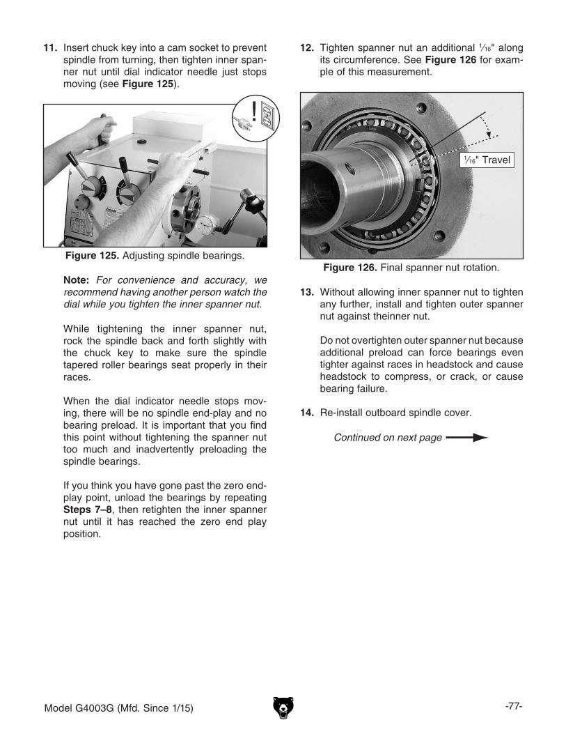
Model G4003G (Mfd. Since 1/15) -77-
11. Insert chuck key into a cam socket to prevent spindle from turning, then tighten inner span-ner nut until dial indicator needle just stops moving (see Figure 125).
Figure 125. Adjusting spindle bearings.
While tightening the inner spanner nut, rock the spindle back and forth slightly with the chuck key to make sure the spindle tapered roller bearings seat properly in their races.
When the dial indicator needle stops mov-
ing, there will be no spindle end-play and no bearing preload. It is important that you find this point without tightening the spanner nut too much and inadvertently preloading the spindle bearings.
If you think you have gone past the zero end-play point, unload the bearings by repeating Steps 7–8, then retighten the inner spanner nut until it has reached the zero end play position.
12. Tighten spanner nut an additional 1⁄16" along its circumference. See Figure 126 for exam-ple of this measurement.
Figure 126. Final spanner nut rotation.
1⁄16" Travel
13. Without allowing inner spanner nut to tighten any further, install and tighten outer spanner nut against theinner nut.
Do not overtighten outer spanner nut because
additional preload can force bearings even tighter against races in headstock and cause headstock to compress, or crack, or cause bearing failure.
14. Re-install outboard spindle cover.
Note: For convenience and accuracy, we recommend having another person watch the dial while you tighten the inner spanner nut.

-78- Model G4003G (Mfd. Since 1/15)
To confirm that the bearings are correctly pre-loaded:
1. Re-attach all removed lathe components and prepare it for operation.
2. Install chuck and tighten jaws.
3. Set spindle speed to its highest setting.
4. Connect lathe to power and start spindle rota-tion at a medium speed.
5. Let lathe run for 20 minutes, periodically checking temperature of spindle nose (refer to the next step).
6. Turn spindle OFF, disconnect lathe from power, and check temperature of spindle.
—If the spindle nose is slightly warm to the touch, you have the correct bearing pre-load.
—If the spindle nose is hotter than you can comfortably keep your hand on, the preload is too tight and you must repeat the bearing preload adjustment procedure. When repeating the procedure, rotate the inner spanner nut a little less during Step 12 in the preceding instructions.

Model G4003G (Mfd. Since 1/15) -79-
SHOCK HAZARD. Working on wiring that is con-nected to a power source is extremely dangerous. Touching electrified parts will result in personal injury including but not limited to severe burns, electrocution, or death. Disconnect the power from the machine before servicing electrical com-ponents!
MODIFICATIONS. Modifying the wiring beyond what is shown in the diagram may lead to unpre-dictable results, including serious injury or fire. This includes the installation of unapproved after-market parts.
WIRE CONNECTIONS. All connections must be tight to prevent wires from loosening during machine operation. Double-check all wires dis-connected or connected during any wiring task to ensure tight connections.
CIRCUIT REQUIREMENTS. You MUST follow the requirements at the beginning of this manualwhen connecting your machine to a power source.
WIRE/COMPONENT DAMAGE. Damaged wires or components increase the risk of serious per-sonal injury, fire, or machine damage. If you notice that any wires or components are damaged while performing a wiring task, replace those wires or components.
MOTOR WIRING. The motor wiring shown inthese diagrams is current at the time of printingbut may not match your machine. If you find thisto be the case, use the wiring diagram inside the motor junction box.
CAPACITORS/INVERTERS. Some capacitorsand power inverters store an electrical charge for up to 10 minutes after being disconnected from the power source. To reduce the risk of being shocked, wait at least this long before working on capacitors.
EXPERIENCING DIFFICULTIES. If you are expe-riencing difficulties understanding the information included in this section, contact our Technical Support at (570) 546-9663.
Wiring Safety Instructions
The photos and diagrams included in this section are best viewed in color. You can view these pages in color at www.grizzly.com.
These pages are current at the time of printing. However, in the spirit of improvement, we may make chang-es to the electrical systems of future machines. Compare the manufacture date of your machine to the one stated in this manual, and study this section carefully.
If there are differences between your machine and what is shown in this section, call Technical Support at (570) 546-9663 for assistance BEFORE making any changes to the wiring on your machine. An updated wiring diagram may be available. Note: Please gather the serial number and manufacture date of your machine before calling. This information can be found on the main machine label.
SECTION 8: WIRINGmachine

-80- Model G4003G (Mfd. Since 1/15)READ ELECTRICAL SAFETY ON PAGE 79!
Electrical Cabinet Wiring Diagram
2 T1 6 T3 22NC 4 T2
1 L1 5 L3 21NC
GSC1-1801
KM1
3 L2
A1
A2
26
30 31 32 33 E
25 24 23 22 21 20
13NO
JZC3 40d
33NO 43NO 23NO
14NO 34NO 44NO 24NO 2 T1 6 T3 22NC 4 T2
1 L1 5 L3 21NC
GSC1-1801
KM2
KA03 L2
Ground
NO NC
1L1 3L2 5L3
2T1 6T34T2
STOP RESET
9598 97
JRS4-09/25d
FR111
13
A
6
96
TC
20-21 = 110V 20-22 = 220V 20-23 = 230V 20-24 = 240V 20-25 = 380V 20-26 = 400V
30-31 110V32-33 24V
A1 A1
A2 A2
L
L
L
N
N
N U1
N
L L L L
L
0
1
1
PE
PE
0 0
1
1
2
U2 U2
U2
Z1 Z1
Z1
Z2
Z2
Z2
2PE PE Z1 U2 U1 PE L N
8
TransformerMTE JBK5-100VATH
Relay
Contactor Contactor Contactor
2A
110V
110V
2A
5A
24V
24V
5A
8
L L
11
11
1
11
11
2
2
11 3
3
3
4 5 6
5
5
5
6
6
7
7
7
0
0
0
0
9 9 10 10
N N
To Work Light(Page 84)
To Power Source(Page 84)
To Spindle Switch(Page 84)
To Control Panel(Page 82)
To Motor(Page 82)

Model G4003G (Mfd. Since 1/15) -81-READ ELECTRICAL SAFETY ON PAGE 79!
Electrical Cabinet Wiring
Figure 127. Electrical cabinet wiring.

-82- Model G4003G (Mfd. Since 1/15)READ ELECTRICAL SAFETY ON PAGE 79!
Motor & Control Panel Wiring Diagrams
Ground
Motor
Control Panel
RunCapacitor20MFD450VAC
StartCapacitor150MFD250VAC
PE
Z2
U1
EmergencyStop/RESET
SS LA103
Inching (Jog)SS LA103
X1
X2
1
U2
Z1
2
3 0
2
6 5
2
0
Power LampSS XD103Power Start
SS LA103
4
To ElectricalCabinet
(Page 80)
To ElectricalCabinet
(Page 80)

Model G4003G (Mfd. Since 1/15) -83-READ ELECTRICAL SAFETY ON PAGE 79!
Motor & Control Panel Wiring
Figure 128. Motor wiring.
Figure 129. Control panel wiring.

-84- Model G4003G (Mfd. Since 1/15)READ ELECTRICAL SAFETY ON PAGE 79!
Other Component Wiring Diagrams
Hot
Hot
Ground
G
1
0
220VNEMA 6-15 Plug
(As Recommended)
LEDWork Light
Spindle Rotation Switch
C
C
NO NO
NC
NC
4 5
1a
1
1b
ON/OFF SwitchKCD1-A
2/8A 250V
Light Socket
7
6
To ElectricalCabinet
(Page 80)
To ElectricalCabinet
(Page 80)
To ElectricalCabinet
(Page 80)

Model G4003G (Mfd. Since 1/15) -85-READ ELECTRICAL SAFETY ON PAGE 79!
Other Component Wiring
Figure 130. Work light wiring.
Figure 131. Spindle switch.

-86- Model G4003G (Mfd. Since 1/15)
Accessories
SECTION 9: PARTS
Please Note: We do our best to stock replacement parts whenever possible, but we cannot guarantee that all parts shown here are available for purchase. Call (800) 523-4777 or visit our online parts store at www.grizzly.com to check for availability.
1
1-2
1-1
2
34
567
910
11
401V2
13
14
15
12
22
23
24
252627
16-21
28
29 3031 32
33
34
138
135
36
36-1 37 38
3935
36-2
36-3
40
REF PART # DESCRIPTION REF PART # DESCRIPTION1 P4003G0001 4-JAW INDEPENDENT CHUCK ASSEMBLY 24 P4003G0024 DEAD CENTER MT#3 CARBIDE TIPPED1-1 P4003G0001-1 4-JAW INDEPENDENT CHUCK BODY 8" 25 P4003G0025 DEAD CENTER MT#3 HSS1-2 P4003G0001-2 4-JAW CHUCK REVERSIBLE JAW 26 P4003G0026 DRILL CHUCK ARBOR MT#3/B162 P4003G0002 FACEPLATE 10" D1-5 27 P4003G0027 SPINDLE SLEEVE MT#5-MT#33 P4003G0003 BOTTLE FOR OIL 28 P4003G0028 QUICK-CHANGE TOOL HOLDER ASSY4 P4003G0004 TOOLBOX 29 P4003G0029 GEAR 45T5 P4003G0005 TOOL POST WRENCH 11MM 30 P4003G0030 GEAR 27T6 P4003G0006 CHUCK WRENCH 4-JAW 31 P4003G0031 GEAR 50T7 P4003G0007 CHUCK WRENCH 3-JAW 32 P4003G0032 GEAR 26T9 P4003G0009 WRENCH 12 X 14MM OPEN-ENDS 33 P4003G0033 GEAR 35T10 P4003G0010 WRENCH 10 X 12MM OPEN-ENDS 34 P4003G0034 GEAR 60T11 P4003G0011 WRENCH 9 X 11MM OPEN-ENDS 35 P4003G0035 TAILSTOCK WRENCH12 P4003G0012 DRILL CHUCK B16 1.5-13MM 36 P4003G0036 3-JAW CHUCK ASSEMBLY 6" D1-5 SCROLL13 P4003G0013 DRILL CHUCK KEY 36-1 P4003G0036-1 3-JAW CHUCK TOP JAW SET14 P4003G0014 SCREWDRIVER PHILLIPS #2 36-2 P4003G0036-2 3-JAW CHUCK BOTTOM JAW SET15 P4003G0015 SCREWDRIVER FLAT #2 36-3 P4003G0036-3 3-JAW CHUCK BODY 6"16 P4003G0016 HEX WRENCH 10MM 37 P4003G0037 QUICK-CHANGE TOOL POST ASSY17 P4003G0017 HEX WRENCH 8MM 38 P4003G0038 STEADY REST ASSEMBLY18 P4003G0018 HEX WRENCH 6MM 39 P4003G0039 FOLLOW REST ASSEMBLY19 P4003G0019 HEX WRENCH 5MM 40 P4003G0040 GEAR 36T20 P4003G0020 HEX WRENCH 4MM 135 P4003G0135 CAP SCREW M8-1.25 X 1621 P4003G0021 HEX WRENCH 2MM 138 P4003G0138 CAMLOCK STUD D1-522 P4003G0022 SPIDER BOLT W/NUT 401V2 P4003G0401V2 HANDWHEEL HANDLE M8-1.25 X 8 V2.04.1223 P4003G0023 LIVE CENTER MT#3

Model G4003G (Mfd. Since 1/15) -87-
Headstock Gearing
101
102103
104105
106107
108104
109
110111 112
113
119
118
117115
116114
125117
167
173
172
171170
169168
167166
165130
117125
130 164
163162 151
130129
154153
160
158
161
159
157
156155152
151117
130150
149
148
130
134
133132131
143144
147
146145
137V2 174
142
141 140139
138-1 136 135
130129
128
126
117127
120121
122123
124122
125

-88- Model G4003G (Mfd. Since 1/15)
Headstock Gearing Parts ListREF PART # DESCRIPTION REF PART # DESCRIPTION101 P4003G0101 EXT RETAINING RING 45MM 138-1 P4003G0138-1 CAMLOCK STUD D1-5102 P4003G0102 GEAR 36T 139 P4003G0139 KEY 8 X 8 X 80103 P4003G0103 GEAR 55T 140 P4003G0140 KEY 8 X 8 X 45 W/1 HOLE104 P4003G0104 KEY 5 X 5 X 18 141 P4003G0141 BUTTON HD CAP SCR M3-.5 X 8105 P4003G0105 GEAR 35T 142 P4003G0142 SPINDLE D1-5106 P4003G0106 EXT RETAINING RING 36MM 143 P4003G0143 KEY 8 X 8 X 210107 P4003G0107 GEAR 45T 144 P4003G0144 CAP SCREW M6-1 X 20108 P4003G0108 GEAR 58T 145 P4003G0145 INBOUND SPINDLE BEARING COVER109 P4003G0109 GEAR 21T 146 P4003G0146 INBOARD BEARING COVER GASKET110 P4003G0110 GEAR 45T 147 P4003G0147 TAPER ROLLER BEARING HR 30212J NSK111 P4003G0111 EXT RETAINING RING 58MM 148 P4003G0148 HEADSTOCK HOUSING112 P4003G0112 GEAR 59T 149 P4003G0149 BEARING BLOCK GASKET113 P4003G0113 GEAR 46T 150 P4003G0150 BEARING BLOCK114 P4003G0114 CAP SCREW M6-1 X 14 151 P4003G0151 INT RETAINING RING 42MM115 P4003G0115 GEAR SHAFT COVER (L) 152 P4003G0152 SHAFT116 P4003G0116 GEAR SHAFT COVER (L) GASKET 153 P4003G0153 OIL SEAL PD25 X 45 X 10117 P4003G0117 BALL BEARING 6004-2RS 154 P4003G0154 GEAR 40T118 P4003G0118 SET SCREW M8-1.25 X 6 155 P4003G0155 TAPER ROLLER BEARING HR 30211J NSK119 P4003G0119 GEAR 83T 156 P4003G0156 SPANNER NUT120 P4003G0120 O-RING 17 X 2.65 157 P4003G0157 KEY 5 X 5 X 8121 P4003G0121 GEAR SHAFT 158 P4003G0158 OUTBOARD BEARING COVER GASKET122 P4003G0122 INT RETAINING RING 47MM 159 P4003G0159 KEY 5 X 5 X 8123 P4003G0123 COMBO GEAR 40/45T 160 P4003G0160 OUTBOUND SPINDLE BEARING COVER124 P4003G0124 BALL BEARING 6004-2RS 161 P4003G0161 CAP SCREW M8-1.25 X 12125 P4003G0125 EXT RETAINING RING 20MM 162 P4003G0162 OIL SEAL PD20 X 45 X 10126 P4003G0126 BUSHING 163 P4003G0163 SPINDLE PULLEY127 P4003G0127 SPACER C5 X 20 STEEL 164 P4003G0164 FENDER WASHER 6MM128 P4003G0128 COMBO GEAR 45/40T 165 P4003G0165 PULLEY SHAFT COVER129 P4003G0129 FLAT WASHER 6MM 166 P4003G0166 PULLEY SHAFT COVER GASKET130 P4003G0130 CAP SCREW M6-1 X 16 167 P4003G0167 SPINDLE PULLEY SHAFT SPACER131 P4003G0131 GEAR SHAFT 168 P4003G0168 KEY 5 X 5 X 30132 P4003G0132 BALL BEARING 6004-2RS 169 P4003G0169 KEY 5 X 5 X 80133 P4003G0133 GEAR SHAFT COVER (R) GASKET 170 P4003G0170 SPINDLE PULLEY SHAFT134 P4003G0134 GEAR SHAFT COVER (R) 171 P4003G0171 GEAR 42T135 P4003G0135 CAP SCREW M6-1 X 16 DOG-PT 172 P4003G0172 GEAR 23T136 P4003G0136 COMPRESSION SPRING 173 P4003G0173 GEAR 47T137V2 P4003G0137V2 SPIDER BOLT SET SCREW M10-1.5 X 30 174 P4003G0174 HEX NUT M10-1.5
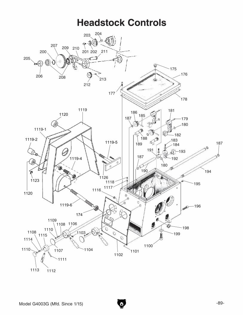
Model G4003G (Mfd. Since 1/15) -89-
Headstock Controls
177
175176
178
179180
182
181185
186
187
188189
183184
193
192
180190
187
11181126
1117
194
187
195
196
199
1100
198
11011102
1103
1104
110611081109
1110
1107
1115
1111
11121113
1110
1114
1108
1116
191
1119
1119-1
1120
1119-2
1123
1119-4
1120
1119-6
1119-5
174
201 202
203 204
211
213212
210209
208
207
206
205
200

-90- Model G4003G (Mfd. Since 1/15)
Headstock Controls Parts ListREF PART # DESCRIPTION REF PART # DESCRIPTION174 P4003G0174 HEX NUT M10-1.5 208 P4003G0208 BALL BEARING 6003-2RS175 P4003G0175 OIL FILL PLUG 3/4" NPT PLASTIC 209 P4003G0209 BUSHING 42 X 25 X 17MM176 P4003G0176 HEADSTOCK TOP COVER 210 P4003G0210 PIVOT ARM177 P4003G0177 CAP SCREW M6-1 X 25 211 P4003G0211 SHAFT178 P4003G0178 HEADSTOCK TOP COVER GASKET 212 P4003G0212 GEAR 40T179 P4003G0179 ROLL PIN 5 X 30 213 P4003G0213 KEY 5 X 5 X 30180 P4003G0180 EXT RETAINING RING 12MM 1100 P4003G1100 CAP SCREW M12-1.75 X 30181 P4003G0181 SPINDLE SPEED SHIFTING ARM 1101 P4003G1101 PHLP HD SCR M3-.5 X 6182 P4003G0182 SPINDLE SPEED SHIFTING FORK 1102 P4003G1102 HEADSTOCK CONTROL PLATE 2-PC ASSY183 P4003G0183 SET SCREW M8-1.25 X 16 1103 P4003G1103 SET SCREW M6-1 X 12184 P4003G0184 HEX NUT M8-1.25 1104 P4003G1104 SPINDLE SPEED HANDLE M8-1.25 X 40185 P4003G0185 ROLL PIN 5 X 25 1106 P4003G1106 SPINDLE SPEED HANDLE HUB186 P4003G0186 GEAR 38T 1107 P4003G1107 SPINDLE SPEED INFORMATION PLATE187 P4003G0187 O-RING 11.2 X 2.65 1108 P4003G1108 STEEL BALL 6MM188 P4003G0188 PINION SHAFT 1109 P4003G1109 COMPRESSION SPRING 1.2 X 4.8 X 27189 P4003G0189 KEY 5 X 5 X 8 1110 P4003G1110 SET SCREW M8-1.25 X 8190 P4003G0190 SHAFT 1111 P4003G1111 ROLL PIN 5 X 40191 P4003G0191 LOCK COLLAR 1112 P4003G1112 FEED DIRECTION HANDLE M10-1.5 X 10192 P4003G0192 FEED DIRECTION SHIFTING ARM 1113 P4003G1113 FEED DIRECTION INFORMATION PLATE193 P4003G0193 FEED DIRECTION SHIFTING FORK 1114 P4003G1114 COMPRESSION SPRING 1 X 5 X 16194 P4003G0194 SPINDLE SPEED SHAFT 1115 P4003G1115 FEED DIRECTION HANDLE HUB195 P4003G0195 CAP SCREW M6-1 X 10 1116 P4003G1116 HEADSTOCK OIL DRAIN PLUG 3/8" NPT196 P4003G0196 CAP SCREW M8-1.25 X 30 1117 P4003G1117 SET SCREW M6-1 X 10198 P4003G0198 OIL SIGHT GLASS M20-1.5 1118 P4003G1118 SET SCREW M6-1 X 6199 P4003G0199 FLAT WASHER 12MM 1119 P4003G1119 END GEAR COVER200 P4003G0200 INT RETAINING RING 35MM 1119-1 P4003G1119-1 SPIDER SAFETY COVER201 P4003G0201 CAP SCREW M6-1 X 12 1119-2 P4003G1119-2 SPIDER COVER KNOB BOLT M16-2.0202 P4003G0202 GEAR FLAT WASHER 6MM 1119-4 P4003G1119-4 STUD-FT M10-1.5 X 35 W/NUTS203 P4003G0203 GEAR 40T 1119-5 P4003G1119-5 END GEAR COVER TOP BOLT M10-1.5 X 78204 P4003G0204 KEY 5 X 5 X 30 1119-6 P4003G1119-6 STUD-DE M10-1.5 X 122 30RH205 P4003G0205 CAP SCREW M6-1 X 12 1120 P4003G1120 KNURLED KNOB M10-1.5206 P4003G0206 COMBO GEAR FLAT WASHER 6MM 1123 P4003G1123 E-CLIP 15MM207 P4003G0207 COMBO GEAR 86T/91T 1126 P4003G1126 CAP SCREW M6-1 X 8
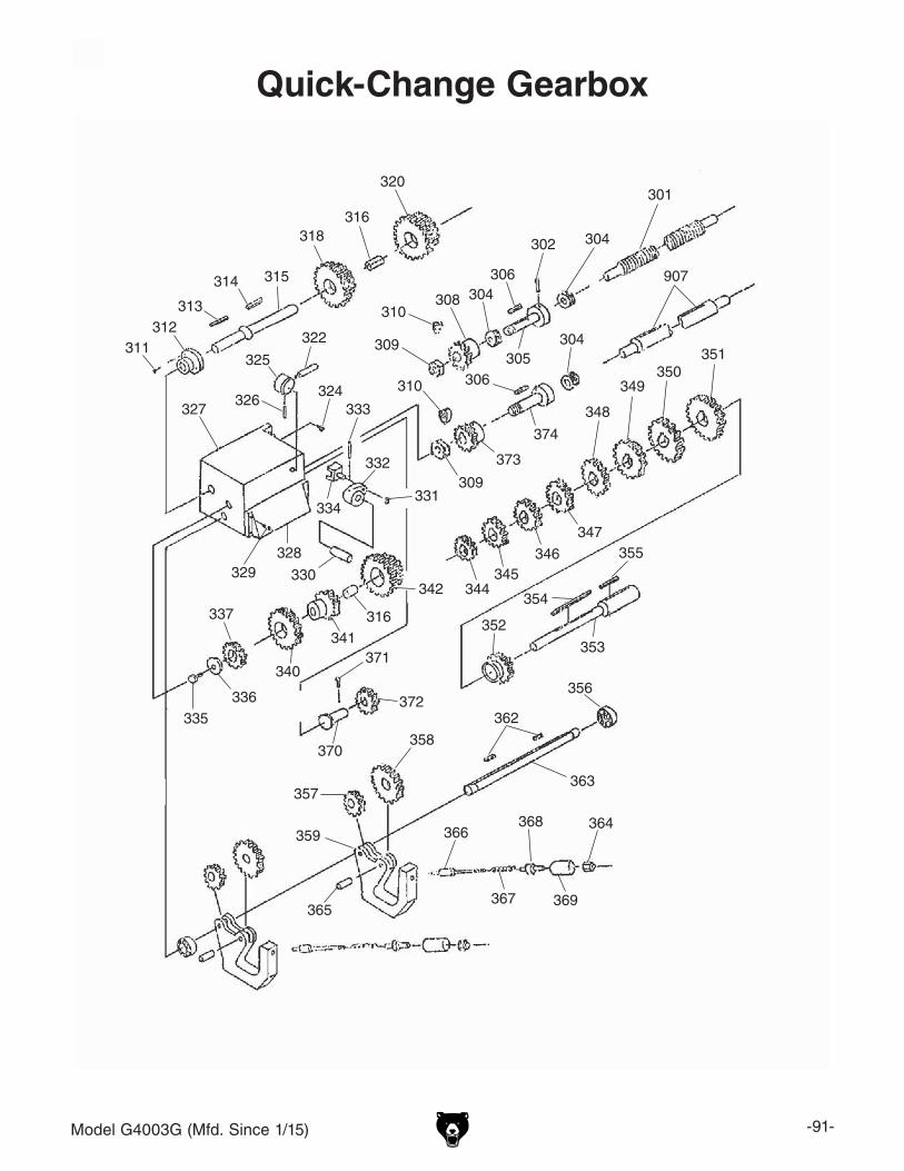
Model G4003G (Mfd. Since 1/15) -91-
Quick-Change Gearbox
311 312
313
314 315
318 316
320 301
304 302
306
305
304 308 310
309 322
325
326 324
327
329 328
330
334
333
332
331 309
310 306
373
374
304 351
350 349
348
347
346 345
344342
316 341
340
337
336 335
370
371
372
352
354
355
353
356
362
358
357
359
365
366
367
368
369
364
907
363

-92- Model G4003G (Mfd. Since 1/15)
Quick-Change Gearbox Parts ListREF PART # DESCRIPTION REF PART # DESCRIPTION301 P4003G0301 LONGITUDINAL LEADSCREW 341 P4003G0341 GEAR 16T302 P4003G0302 ROLL PIN 5 X 36 342 P4003G0342 COMBO GEAR 3PC SET304 P4003G0304 THRUST BEARING 8103 344 P4003G0344 GEAR 16T305 P4003G0305 LEADSCREW CONNECTOR 345 P4003G0345 GEAR 18T306 P4003G0306 KEY 5 X 5 X 14 346 P4003G0346 GEAR 19T308 P4003G0308 GEAR 24T 347 P4003G0347 GEAR 20T309 P4003G0309 HEX NUT M12-1.75 348 P4003G0348 GEAR 22T310 P4003G0310 GEAR FLAT WASHER 12MM 349 P4003G0349 GEAR 24T311 P4003G0311 CAP SCREW M6-1 X 16 350 P4003G0350 GEAR 26T312 P4003G0312 END CAP 351 P4003G0351 GEAR 28T313 P4003G0313 KEY 5 X 5 X 30 352 P4003G0352 GEAR 24T314 P4003G0314 KEY 5 X 5 X 10 353 P4003G0353 SHAFT315 P4003G0315 SHAFT 354 P4003G0354 KEY 5 X 5 X 75316 P4003G0316 BUSHING 355 P4003G0355 KEY 5 X 5 X 40318 P4003G0318 COMBO GEAR 32/16T 356 P4003G0356 BALL BEARING 6002-2RS320 P4003G0320 COMBO GEAR 32/16T 357 P4003G0357 GEAR 16T322 P4003G0322 FEED SELECTION HANDLE 358 P4003G0358 GEAR 32T W/BUSHING324 P4003G0324 HEX BOLT M10-1.5 X 30 359 P4003G0359 QUICK-CHANGE SHIFT LEVER325 P4003G0325 FEED SELECTION HUB 362 P4003G0362 KEY 5 X 5 X 32326 P4003G0326 ROLL PIN 5 X 40 363 P4003G0363 SHIFT ROD327 P4003G0327 GEARBOX CASTING 364 P4003G0364 HEX NUT M6-1328 P4003G0328 QUICK-CHANGE SELECTION PLATE 365 P4003G0365 SHAFT329 P4003G0329 CAP SCREW M6-1 X 16 366 P4003G0366 SHAFT330 P4003G0330 SHAFT 367 P4003G0367 EXTENSION SPRING331 P4003G0331 E-CLIP 13MM 368 P4003G0368 SPRING RETAINER332 P4003G0332 SHIFT PIVOT 369 P4003G0369 SPRING HOUSING333 P4003G0333 ROLL PIN 4 X 30 370 P4003G0370 SHAFT334 P4003G0334 SHIFT FORK 371 P4003G0371 SET SCREW M8-1.25 X 8335 P4003G0335 CAP SCREW M6-1 X 12 372 P4003G0372 GEAR 15T336 P4003G0336 GEAR FLAT WASHER 6MM 373 P4003G0373 GEAR 24T337 P4003G0337 GEAR 16T 374 P4003G0374 SHAFT340 P4003G0340 GEAR 32T 907 P4003G0907 SPINDLE ROD
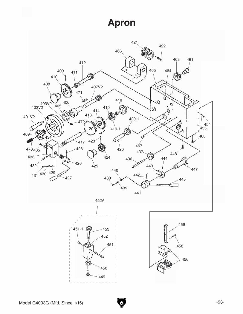
Model G4003G (Mfd. Since 1/15) -93-
Apron
421422
466
463 461
464465
459
458
456
455454
447
445
443
444448
441
442
468
440
439
438
467420
420-1
425
424
423
415
427
426
428
417
431 430 429
432
433
435
434
413414
419
419-1
418406
407V2471
408
410
409 411
412
436
437
453
452
452A
451
450
449
451-1
403V2405
401V2
402V2
472
470
469

-94- Model G4003G (Mfd. Since 1/15)
Apron Parts ListREF PART # DESCRIPTION REF PART # DESCRIPTION401V2 P4003G0401V2 HANDWHEEL HANDLE M8-1.25 X 8 V2.04.12 436 P4003G0436 SHAFT402V2 P4003G0402V2 CARRIAGE HANDWHEEL V2.04.12 437 P4003G0437 SAFETY SHIFTER403V2 P4003G0403V2 GRADUATED DIAL V2.04.12 438 P4003G0438 SET SCREW M8-1.25 X 6405 P4003G0405 SET SCREW M6-1 X 20 439 P4003G0439 COMPRESSION SPRING406 P4003G0406 HANDWHEEL BRACKET 440 P4003G0440 STEEL BALL 6MM407V2 P4003G0407V2 GEAR SHAFT 12T W/KEYWAY V2.04.12 441 P4003G0441 HALF NUT LEVER HUB408 P4003G0408 CASTING PLUG 442 P4003G0442 ROLL PIN 6 X 40409 P4003G0409 ROLL PIN 5 X 30 443 P4003G0443 HALF NUT DOG410 P4003G0410 GEAR 50T 444 P4003G0444 SET SCREW M8-1.25 X 30411 P4003G0411 EXT RETAINING RING 19MM 445 P4003G0445 HALF NUT LEVER M8-1.25 X 8 155L412 P4003G0412 GEAR SHAFT 11T 447 P4003G0447 SHAFT413 P4003G0413 GEAR 48T 448 P4003G0448 CAP SCREW M6-1 X 65414 P4003G0414 GEAR 51T 449 P4003G0449 CAP SCREW M6-1 X 15415 P4003G0415 ROLL PIN 5 X 30 450 P4003G0450 GEAR 16T417 P4003G0417 WORM SHAFT 451 P4003G0451 CAP SCREW M6-1 X 60 BLK C12.9 USA418 P4003G0418 END CAP 451-1 P4003G0451-1 SLEEVE419 P4003G0419 GEAR 25T 452 P4003G0452 THREAD DIAL BODY419-1 P4003G0419-1 SPACER 452A P4003G0452A THREADED DIAL ASSEMBLY420 P4003G0420 SHAFT 453 P4003G0453 THREAD DIAL420-1 P4003G0420-1 GEAR 24T 454 P4003G0454 HEX NUT M6-1421 P4003G0421 WORM GEAR 455 P4003G0455 SET SCREW M6-1 X 16422 P4003G0422 KEY 5 X 5 X 45 456 P4003G0456 HALF NUT 2-PC423 P4003G0423 ROLL PIN 5 X 24 458 P4003G0458 CAP SCREW M6-1 X 25424 P4003G0424 GEAR 14T 459 P4003G0459 HALF NUT GIB425 P4003G0425 CASTING PLUG 461 P4003G0461 SHAFT426 P4003G0426 GEAR SHAFT 10T 463 P4003G0463 GEAR 25T427 P4003G0427 FEED SELECTION LEVER M8-1.25 X 8 464 P4003G0464 SET SCREW M6-1 X 6428 P4003G0428 ROLL PIN 5 X 24 465 P4003G0465 APRON HOUSING429 P4003G0429 STEEL BALL 6MM 466 P4003G0466 WORM BRACKET430 P4003G0430 COMPRESSION SPRING 467 P4003G0467 OIL SIGHT GLASS M20-1.5431 P4003G0431 SET SCREW M6-1 X 8 468 P4003G0468 CAP SCREW M10-1.5 X 20432 P4003G0432 CAP SCREW M6-1 X 45 469 P4003G0469 HANDWHEEL RETAINER433 P4003G0433 FEED SELECTION BRACKET 470 P4003G0470 SET SCREW M6-1 X 20434 P4003G0434 FLAT WASHER 6MM 471 P4003G0471 KEY 5 X 5 X 20435 P4003G0435 CAP SCREW M6-1 X 40 472 P4003G0472 SET SCREW M6-1 X 8
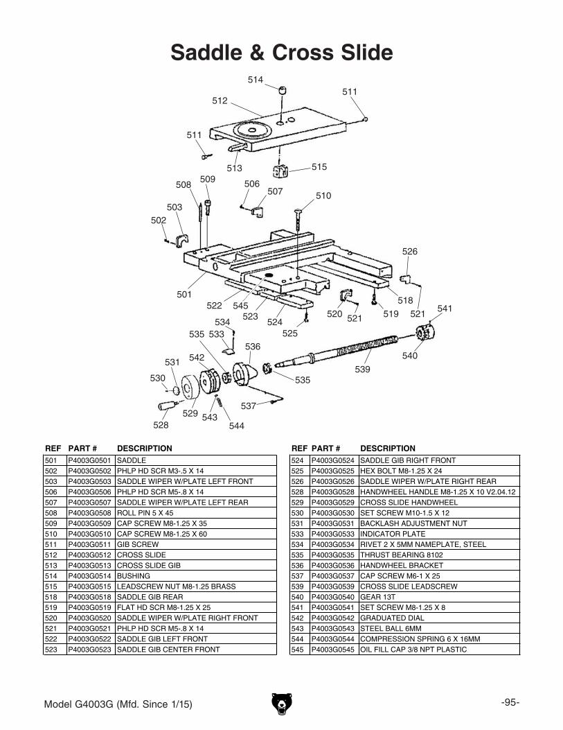
Model G4003G (Mfd. Since 1/15) -95-
Saddle & Cross Slide514
512511
513
511
515
502503
508509 506
507 510
518
526
521519521520
525524
523522 545
501
528543
544
530
531
529
542
535
537
536
534533
535539
540
541
REF PART # DESCRIPTION REF PART # DESCRIPTION501 P4003G0501 SADDLE 524 P4003G0524 SADDLE GIB RIGHT FRONT502 P4003G0502 PHLP HD SCR M3-.5 X 14 525 P4003G0525 HEX BOLT M8-1.25 X 24503 P4003G0503 SADDLE WIPER W/PLATE LEFT FRONT 526 P4003G0526 SADDLE WIPER W/PLATE RIGHT REAR 506 P4003G0506 PHLP HD SCR M5-.8 X 14 528 P4003G0528 HANDWHEEL HANDLE M8-1.25 X 10 V2.04.12507 P4003G0507 SADDLE WIPER W/PLATE LEFT REAR 529 P4003G0529 CROSS SLIDE HANDWHEEL508 P4003G0508 ROLL PIN 5 X 45 530 P4003G0530 SET SCREW M10-1.5 X 12509 P4003G0509 CAP SCREW M8-1.25 X 35 531 P4003G0531 BACKLASH ADJUSTMENT NUT510 P4003G0510 CAP SCREW M8-1.25 X 60 533 P4003G0533 INDICATOR PLATE511 P4003G0511 GIB SCREW 534 P4003G0534 RIVET 2 X 5MM NAMEPLATE, STEEL512 P4003G0512 CROSS SLIDE 535 P4003G0535 THRUST BEARING 8102513 P4003G0513 CROSS SLIDE GIB 536 P4003G0536 HANDWHEEL BRACKET514 P4003G0514 BUSHING 537 P4003G0537 CAP SCREW M6-1 X 25515 P4003G0515 LEADSCREW NUT M8-1.25 BRASS 539 P4003G0539 CROSS SLIDE LEADSCREW518 P4003G0518 SADDLE GIB REAR 540 P4003G0540 GEAR 13T519 P4003G0519 FLAT HD SCR M8-1.25 X 25 541 P4003G0541 SET SCREW M8-1.25 X 8520 P4003G0520 SADDLE WIPER W/PLATE RIGHT FRONT 542 P4003G0542 GRADUATED DIAL521 P4003G0521 PHLP HD SCR M5-.8 X 14 543 P4003G0543 STEEL BALL 6MM522 P4003G0522 SADDLE GIB LEFT FRONT 544 P4003G0544 COMPRESSION SPRING 6 X 16MM523 P4003G0523 SADDLE GIB CENTER FRONT 545 P4003G0545 OIL FILL CAP 3/8 NPT PLASTIC

-96- Model G4003G (Mfd. Since 1/15)
Compound Rest & Tool Holder
654
652
653
651
650
649
647
603
611
613
612
619
614 616
615
617A
618
617
621620
642
610
601
601
607
646645644
643
604
602
648
641
640
659
660
28 37
658
657
656
655
605

Model G4003G (Mfd. Since 1/15) -97-
Compound Rest & Tool Holder Parts ListREF PART # DESCRIPTION REF PART # DESCRIPTION28 P4003G0028 QUICK-CHANGE TOOL HOLDER ASSY 640 P4003G0640 PLUNGER37 P4003G0037 QUICK-CHANGE TOOL POST ASSY 641 P4003G0641 COMPRESSION SPRING601 P4003G0601 GIB SCREW 642 P4003G0642 KEY 4 X 4 X 10602 P4003G0602 COMPOUND REST GIB 643 P4003G0643 FLAT WASHER 8MM603 P4003G0603 COMPOUND REST 644 P4003G0644 SWIVEL SLIDE604 P4003G0604 HEX NUT M8-1.25 645 P4003G0645 SET SCREW M6-1 X 16605 P4003G0605 COMPOUND REST MOUNTING BOLT 646 P4003G0646 HEX NUT M6-1607 P4003G0607 COMPOUND REST LEADSCREW NUT 647 P4003G0647 BALL OILER 8MM TAP-IN610 P4003G0610 COMPOUND REST LEADSCREW 648 P4003G0648 SET SCREW M6-1 X 8611 P4003G0611 THRUST BEARING 8101 649 P4003G0649 TOOL POST BOLT M16-1.5 X 35612 P4003G0612 HANDWHEEL BRACKET 650 P4003G0650 QUICK CHANGE TOOL POST BLOCK613 P4003G0613 THRUST BEARING 8101 651 P4003G0651 TOOL POST BUSHING614 P4003G0614 GRADUATED DIAL 652 P4003G0652 TOOL POST HANDLE HUB615 P4003G0615 BACKLASH ADJUSTMENT NUT 653 P4003G0653 FLANGE NUT M16-1.5616 P4003G0616 COMPOUND REST HANDWHEEL 654 P4003G0654 TOOL POST HANDLE M12-1.75 X 8617 P4003G0617 HANDLE LARGE M5-.8 X 10 50L 655 P4003G0655 HEX NUT M10-1617A P4003G0617A HANDLE SMALL M5-.8 X 10 35L 656 P4003G0656 WAVY WASHER 10MM618 P4003G0618 SET SCREW M5-.8 X 5 657 P4003G0657 KNURLED THUMB NUT M10-1619 P4003G0619 CAP SCREW M6-1 X 15 658 P4003G0658 SET SCREW M10-1 X 45620 P4003G0620 STEEL BALL 6MM 659 P4003G0659 SET SCREW M10-1.5 X 14 DOG-PT621 P4003G0621 COMPRESSION SPRING 6 X 16MM 660 P4003G0660 TOOL HOLDER BODY
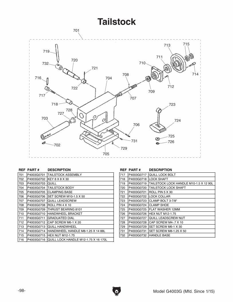
-98- Model G4003G (Mfd. Since 1/15)
Tailstock
719
732720
721
722
704
707
708
709
710
712
711
713
714
715
723
725
726
706
731
729
705
702
703727
728
718
717
716
724
701
REF PART # DESCRIPTION REF PART # DESCRIPTION701 P4003G0701 TAILSTOCK ASSEMBLY 717 P4003G0717 QUILL LOCK BOLT702 P4003G0702 KEY 8 X 8 X 30 718 P4003G0718 LOCK SHAFT703 P4003G0703 QUILL 719 P4003G0719 TAILSTOCK LOCK HANDLE M10-1.5 X 12 90L704 P4003G0704 TAILSTOCK BODY 720 P4003G0720 TAILSTOCK LOCK SHAFT705 P4003G0705 CLAMPING BASE 721 P4003G0721 ROLL PIN 5 X 30706 P4003G0706 SET SCREW M10-1.5 X 50 722 P4003G0722 LOCK COLLAR707 P4003G0707 QUILL LEADSCREW 723 P4003G0723 CLAMP BOLT 3-7/8"708 P4003G0708 ROLL PIN 4 X 10 724 P4003G0724 CLAMP SHOE709 P4003G0709 THRUST BEARING 8101 725 P4003G0725 FLAT WASHER 12MM710 P4003G0710 HANDWHEEL BRACKET 726 P4003G0726 HEX NUT M12-1.75711 P4003G0711 GRADUATED DIAL 727 P4003G0727 QUILL LEADSCREW NUT712 P4003G0712 CAP SCREW M6-1 X 20 728 P4003G0728 CAP SCREW M4-.7 X 10713 P4003G0713 QUILL HANDWHEEL 729 P4003G0729 SET SCREW M6-1 X 30714 P4003G0714 HANDWHEEL HANDLE M8-1.25 X 14 88L 731 P4003G0731 SET SCREW M8-1.25 X 50715 P4003G0715 HEX NUT M12-1.75 732 P4003G0732 HANDLE BASE716 P4003G0716 QUILL LOCK HANDLE M12-1.75 X 16 170L

Model G4003G (Mfd. Since 1/15) -99-
Bed & Motor
REF PART # DESCRIPTION REF PART # DESCRIPTION801 P4003G0801 COGGED V-BELT V13X795 185 P10 3606 808 P4003G0808 MOTOR PULLEY802 P4003G0802 SET SCREW M5-.8 X 10 809 P4003G0809 MOTOR MOUNT803 P4003G0803 KEY 8 X 8 X 60 810 P4003G0810 HEX BOLT M10-1.5 X 30804 P4003G0804 FLAT WASHER 10MM 811 P4003G0811 ROLL PIN 5 X 25805 P4003G0805 HEX BOLT M10-1.5 X 25 812 P4003G0812 FLAT WASHER 10MM806 P4003G0806 MOTOR 2HP 220V 1-PH 813 P4003G0813 CAP SCREW M6-1 X 25806-1 P4003G0806-1 MOTOR FAN COVER 814 P4003G0814 GAP RACK806-2 P4003G0806-2 MOTOR FAN 815 P4003G0815 GAP INSERT806-3 P4003G0806-3 MOTOR JUNCTION BOX 816 P4003G0816 CAP SCREW M10-1.5 X 45806-4 P4003G0806-4 MOTOR TERMINAL BLOCK 817 P4003G0817 THREADED TAPER PIN806-5 P4003G0806-5 MOTOR CAPACITOR COVER 818 P4003G0818 PHLP HD SCR M6-1 X 10806-6 P4003G0806-6 S CAPACITOR 150M 250V 819 P4003G0819 FLAT WASHER 6MM806-8 P4003G0806-8 R CAPACITOR 20M 450V 820 P4003G0820 LATHE BED806-9 P4003G0806-9 BALL BEARING 5205ZZ 821 P4003G0821 CHIP PAN806-10 P4003G0806-10 BALL BEARING 5205ZZ 822 P4003G0822 BED RACK806-11 P4003G0806-11 CENT SWITCH 823 P4003G0823 RIVET 2 X 5MM NAMEPLATE, STEEL806-12 P4003G0806-12 CONTACT PLATE 824 P4003G0824 INFORMATION PLATE807 P4003G0807 SPLASH GUARD 828 P4003G0828 MOTOR MOUNT SPACER BLOCK
801
819
818
807
819818
815
816
817
802
803
804
805808
828809
812
810
811813
814
811
813
822
824
823821
820
806
806-1
806-2
806-3
806-4
806-5806-6
806-8
806-9
806-10
806-11
806-12

-100- Model G4003G (Mfd. Since 1/15)
Stand
838
837
820
821836
830
818
819
835833
818
819
834
829
829-1
829-2
829-2
829A
836-1
836A
REF PART # DESCRIPTION REF PART # DESCRIPTION818 P4003G0818 PHLP HD SCR M6-1 X 10 833 P4003G0833 CENTER PANEL819 P4003G0819 FLAT WASHER 6MM 834 P4003G0834 PANEL BRACKET LEFT820 P4003G0820 LATHE BED 835 P4003G0835 HEX NUT M6-1821 P4003G0821 CHIP PAN 836 P4003G0836 LEFT STAND829 P4003G0829 RIGHT STAND 836-1 P4003G0836-1 LEFT STAND DOOR829-1 P4003G0829-1 RIGHT STAND DOOR 836A P4003G0836A LEFT STAND ASSEMBLY829-2 P4003G0829-2 DOOR LATCH 837 P4003G0837 FLAT WASHER 14MM829A P4003G0829A RIGHT STAND ASSEMBLY 838 P4003G0838 HEX BOLT M14-2 X 50830 P4003G0830 PANEL BRACKET RIGHT

Model G4003G (Mfd. Since 1/15) -101-
Feed Rod
919V2
918V2
917
916
915
914
913 911
910
909908
907V2
912
920
921
922
923
924
906
905
904
902
903
902
901
REF PART # DESCRIPTION REF PART # DESCRIPTION901 P4003G0901 END BRACKET 913 P4003G0913 CAP SCREW M6-1 X 14902 P4003G0902 CAP SCREW M6-1 X 12 914 P4003G0914 ROLL PIN 5 X 25903 P4003G0903 BALL OILER 8MM TAP-IN 915 P4003G0915 SUPPORT BRACKET904 P4003G0904 ROLL PIN 6 X 55 916 P4003G0916 EXT RETAINING RING 30MM905 P4003G0905 SET SCREW M6-1 X 6 917 P4003G0917 CAP SCREW M8-1.25 X 25906 P4003G0906 LOCK COLLAR 12 X 20 X 34MM 918V2 P4003G0918V2 CONNECTION BRACKET V2.12.14907V2 P4003G0907V2 SPINDLE ROD V2.12.14 919V2 P4003G0919V2 SPINDLE ON/OFF SWITCH V2.12.14908 P4003G0908 KEY 5 X 5 X 35 920 P4003G0920 CAP SCREW M4-.7 X 6909 P4003G0909 ROLL PIN 4 X 20 921 P4003G0921 SET SCREW M6-1 X 8910 P4003G0910 COMPRESSION SPRING 7020 922 P4003G0922 SPINDLE SWITCH ARM911 P4003G0911 SPINDLE SWITCH HANDLE M10-1.5 X 16 923 P4003G0923 SPINDLE SWITCH BOX912 P4003G0912 HANDLE BRACKET 924 P4003G0924 BUTTON HD CAP SCR M4-.7 X 45

-102- Model G4003G (Mfd. Since 1/15)
Machine Labels
Safety labels help reduce the risk of serious injury caused by machine hazards. If any label comes off or becomes unreadable, the owner of this machine MUST replace it in the original location before resuming operations. For replacements, contact (800) 523-4777 or www.grizzly.com.
REF PART # DESCRIPTION REF PART # DESCRIPTION1000 P4003G1000 MODEL NUMBER LABEL 1005 P4003G1005 ENTANGLEMENT HAZARD LABEL1001 P4003G1001 GRIZZLY NAMEPLATE-MINI 1006 P4003G1006 SAFETY GLASSES LABEL1002 P4003G1002 ELECTRICITY LABEL 1007 P4003G1007 MACHINE ID LABEL1003 P4003G1003 DISCONNECT LABEL 1009 P4003G1009 PINCH/ENTANGLEMENT HAZARD LABEL1004 P4003G1004 READ MANUAL LABEL 1010 P4003G1010 OUTBOARD WARNING STRIP LABEL
1000
1001
1002(Motor Junction Box)
1002(Electrical Cabinet Door)
1003
1004
1005
1006
1007
10091010

Model G4003G (Mfd. Since 1/15) -103-
Electrical Components
REF PART # DESCRIPTION REF PART # DESCRIPTION1201 P4003G1201 TRANSFORMER MTE JBK5-100VATH 1209 P4003G1209 TERMINAL BLOCK 20-POLE1202 P4003G1202 FUSE HOLDER 2A 1210 P4003G1210 E-STOP RESET BUTTON SS LA1031202-1 P4003G1202-1 FUSE 2A 1211 P4003G1211 POWER START BUTTON SS LA1031203A P4003G1203A FUSE 5A 1212 P4003G1212 JOG BUTTON SS LA1031203V2 P4003G1203V2 FUSE HOLDER 5A V2.10.06 1213 P4003G1213 POWER LAMP SS XD1031204-1 P4003G1204-1 OL RELAY TIANSHUI JR58-09/25D 110V 1214 P4003G1214 WORK LIGHT TERMINAL BLOCK1205 P4003G1205 CONTACTOR TIANSHUI GSC1-1801 1215 P4003G1215 HALOGEN WORK LIGHT ASSY1206 P4003G1206 CONTACTOR TIANSHUI JZC3 40D 1215-1 P4003G1215-1 CORD FOR WORK LIGHT1207 P4003G1207 GROUND TERMINAL BLOCK 1215-3V2 P4003G1215-3V2 LED BULB 12V 3W BI-PIN1208 P4003G1208 TERMINAL BLOCK 12-POLE
1201 1202 1204-1
1205 1206
1207 1208 1209
1210 1211 1212
1213
1214
1215
2A
1202-1
1203V2
5A
1203A
1215-1
1215-3V2
24V
24V

-104- Model G4003G (Mfd. Since 1/15)
Steady Rest Follow Rest1300
13011302
1303 1304
1305
1305A
1306
1306-1
1306-2
130713091310
1311
1312
1313
1314
1315
13161317
1319
REF PART # DESCRIPTION1300 P4003G1300 STEADY REST ASSEMBLY1301 P4003G1301 KNURLED FINGER KNOB1302 P4003G1302 SET SCREW M6-1 X 6 CONE-PT1303 P4003G1303 BUSHING1304 P4003G1304 FINGER ADJUSTMENT SCREW1305 P4003G1305 FINGER SLEEVE 3"1305A P4003G1305A FINGER 3" W/BEARING ASSEMBLY1306 P4003G1306 SET SCREW M6-1 X 81306-1 P4003G1306-1 SET SCREW M6-1 X 16 DOG-PT1306-2 P4003G1306-2 HEX NUT M6-11307 P4003G1307 UPPER STEADY REST CASTING1309 P4003G1309 BALL BEARING 625ZZ1310 P4003G1310 DOWEL PIN 5 X 161311 P4003G1311 LOWER STEADY REST CASTING1312 P4003G1312 LOCK PIN1313 P4003G1313 LOCK BOLT M10-1.5 X 181314 P4003G1314 HEX NUT M12-1.751315 P4003G1315 FLAT WASHER 12MM1316 P4003G1316 CLAMP PLATE1317 P4003G1317 T-BOLT M12-1.75 X 751319 P4003G1319 KNURLED THUMB KNOB M10-1.5
1400
1401 1402
14031404
1405A1405
1406
14071408
14091410
1411
1412
REF PART # DESCRIPTION1400 P4003G1400 FOLLOW REST ASSEMBLY1401 P4003G1401 KNURLED FINGER KNOB1402 P4003G1402 SET SCREW M6-1 X 6 CONE-PT1403 P4003G1403 BUSHING1404 P4003G1404 FINGER ADJUSTMENT SCREW1405 P4003G1405 FINGER SLEEVE 3"1405A P4003G1405A FINGER 3" W/BEARING ASSEMBLY1406 P4003G1406 SET SCREW M6-1 X 81407 P4003G1407 HEX NUT M6-11408 P4003G1408 SET SCREW M6-1 X 16 DOG-PT1409 P4003G1409 FOLLOW REST CASTING1410 P4003G1410 CAP SCREW M8-1.25 x 351411 P4003G1411 BALL BEARING 625ZZ1412 P4003G1412 DOWEL PIN 5 X 16
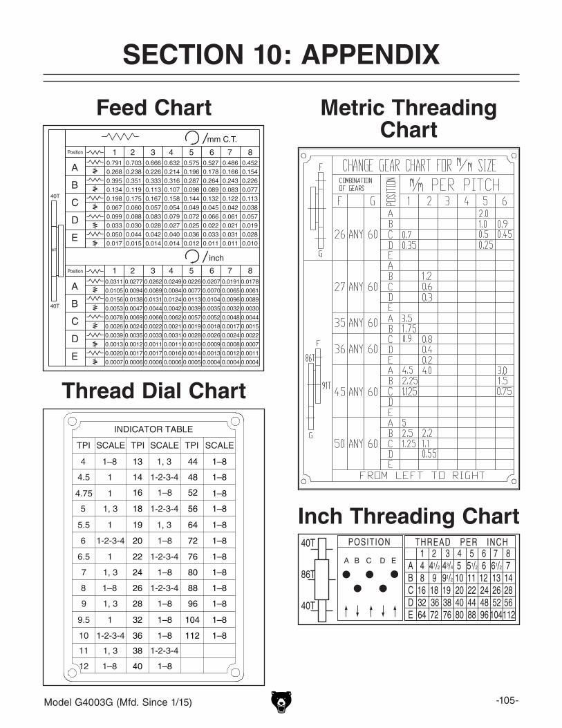
Model G4003G (Mfd. Since 1/15) -105-
SECTION 10: APPENDIX
Feed Chart Metric Threading Chart
Inch Threading Chart40T
40T
86T
Thread Dial Chart
TPI TPI TPISCALE SCALE SCALE
INDICATOR TABLE
4
4.5
4.75
5
5.5
6
6.5
7
8
9
9.5
10
11
12
13
14
16
18
19
20
22
24
26
28
32
36
38
40
44
48
52
56
64
72
76
80
88
96
104
112
1-2-3-4
1, 31–8
1–8
1–8
1–8
1–8
1–8
1–8
1–8
1–8
1–8
1–8
1–8
1–8
1–8
1–8
1–8
1–8
1–8
1–8
1–8
1–8
1–8
1
1
1
1
1
1, 3
1, 3
1, 3
1, 3
1, 3
1-2-3-4
1-2-3-4
1-2-3-4
1-2-3-4
1-2-3-4
1-2-3-4

-106- Model G4003G (Mfd. Since 1/15)

CU
T A
LON
G D
OT
TE
D L
INE
Name _____________________________________________________________________________
Street _____________________________________________________________________________
City _______________________ State _________________________ Zip _____________________
Phone # ____________________ Email _________________________________________________
Model # ____________________ Order # _______________________ Serial # __________________
WARRANTY CARD
The following information is given on a voluntary basis. It will be used for marketing purposes to help us develop better products and services. Of course, all information is strictly confidential.
1. How did you learn about us? ____ Advertisement ____ Friend ____ Catalog ____ Card Deck ____ Website ____ Other:
2. Which of the following magazines do you subscribe to?
3. What is your annual household income? ____ $20,000-$29,000 ____ $30,000-$39,000 ____ $40,000-$49,000 ____ $50,000-$59,000 ____ $60,000-$69,000 ____ $70,000+
4. What is your age group? ____ 20-29 ____ 30-39 ____ 40-49 ____ 50-59 ____ 60-69 ____ 70+
5. How long have you been a woodworker/metalworker? ____ 0-2 Years ____ 2-8 Years ____ 8-20 Years ____20+ Years
6. How many of your machines or tools are Grizzly? ____ 0-2 ____ 3-5 ____ 6-9 ____10+
7. Do you think your machine represents a good value? _____Yes _____No
8. Would you recommend Grizzly Industrial to a friend? _____Yes _____No
9. Would you allow us to use your name as a reference for Grizzly customers in your area? Note: We never use names more than 3 times. _____Yes _____No
10. Comments: _____________________________________________________________________
_________________________________________________________________________________
_________________________________________________________________________________
_________________________________________________________________________________
____ Cabinetmaker & FDM____ Family Handyman____ Hand Loader____ Handy____ Home Shop Machinist____ Journal of Light Cont.____ Live Steam____ Model Airplane News____ Old House Journal____ Popular Mechanics
____ Popular Science____ Popular Woodworking____ Precision Shooter____ Projects in Metal____ RC Modeler____ Rifle____ Shop Notes____ Shotgun News____ Today’s Homeowner____ Wood
____ Wooden Boat____ Woodshop News____ Woodsmith____ Woodwork____ Woodworker West____ Woodworker’s Journal____ Other:

TAPE ALONG EDGES--PLEASE DO NOT STAPLE
FOLD ALONG DOTTED LINE
FOLD ALONG DOTTED LINE
GRIZZLY INDUSTRIAL, INC.P.O. BOX 2069BELLINGHAM, WA 98227-2069
PlaceStampHere
Name_______________________________
Street_______________________________
City______________State______Zip______
Send a Grizzly Catalog to a friend:

WARRANTY & RETURNSGrizzly Industrial, Inc. warrants every product it sells for a period of 1 year to the original purchaser from the date of purchase. This warranty does not apply to defects due directly or indirectly to misuse, abuse, negligence, accidents, repairs or alterations or lack of maintenance. This is Grizzly’s sole written warranty and any and all warranties that may be implied by law, including any merchantability or fitness, for any par-ticular purpose, are hereby limited to the duration of this written warranty. We do not warrant or represent that the merchandise complies with the provisions of any law or acts unless the manufacturer so warrants. In no event shall Grizzly’s liability under this warranty exceed the purchase price paid for the product and any legal actions brought against Grizzly shall be tried in the State of Washington, County of Whatcom.
We shall in no event be liable for death, injuries to persons or property or for incidental, contingent, special, or consequential damages arising from the use of our products.
To take advantage of this warranty, contact us by mail or phone and give us all the details. We will then issue you a “Return Number,’’ which must be clearly posted on the outside as well as the inside of the carton. We will not accept any item back without this number. Proof of purchase must accompany the merchandise.
The manufacturers reserve the right to change specifications at any time because they constantly strive to achieve better quality equipment. We make every effort to ensure that our products meet high quality and durability standards and we hope you never need to use this warranty.
Please feel free to write or call us if you have any questions about the machine or the manual.
Thank you again for your business and continued support. We hope to serve you again soon.