model g4179 1 hp - grizzlycdn0.grizzly.com/manuals/g4179_m.pdf · g4179 when the manual was...
TRANSCRIPT

MODEL G4179 1⁄2 HP POWER FEEDER
OWNER'S MANUAL
COPYRIGHT © JUNE, 2008 BY GRIZZLY INDUSTRIAL, INC., REVISED JUNE, 2015 (ST)WARNING: NO PORTION OF THIS MANUAL MAY BE REPRODUCED IN ANY SHAPE
OR FORM WITHOUT THE WRITTEN APPROVAL OF GRIZZLY INDUSTRIAL, INC. #CR10816 PRINTED IN TAIWAN

This manual provides critical safety instructions on the proper setup, operation, maintenance, and service of this machine/tool. Save this document, refer to it often, and use it to instruct other operators.
Failure to read, understand and follow the instructions in this manual may result in fire or serious personal injury—including amputation, electrocution, or death.
The owner of this machine/tool is solely responsible for its safe use. This responsibility includes but is not limited to proper installation in a safe environment, personnel training and usage authorization, proper inspection and maintenance, manual availability and compre-hension, application of safety devices, cutting/sanding/grinding tool integrity, and the usage of personal protective equipment.
The manufacturer will not be held liable for injury or property damage from negligence, improper training, machine modifications or misuse.
Some dust created by power sanding, sawing, grinding, drilling, and other construction activities contains chemicals known to the State of California to cause cancer, birth defects or other reproductive harm. Some examples of these chemicals are:
• Lead from lead-based paints.• Crystalline silica from bricks, cement and other masonry products.• Arsenic and chromium from chemically-treated lumber.
Your risk from these exposures varies, depending on how often you do this type of work. To reduce your exposure to these chemicals: Work in a well ventilated area, and work with approved safety equip-ment, such as those dust masks that are specially designed to filter out microscopic particles.

Model G4179 1⁄2 HP Power Feeder -1-
Table of ContentsINTRODUCTION ............................................... 2
Foreword ........................................................ 2Contact Info.................................................... 2Functional Overview ...................................... 2Machine Data Sheet ...................................... 3Identification ................................................... 5
SECTION 1: SAFETY ....................................... 6Safety Instructions for Machinery .................. 6Additional Safety for Power Feeders ............. 8
SECTION 2: CIRCUIT REQUIREMENTS ........ 9220V Single-Phase ........................................ 9
SECTION 3: SETUP ....................................... 10Setup Safety ................................................ 10Items Needed for Setup ............................... 10Unpacking .................................................... 10Inventory ...................................................... 11Hardware Recognition Chart ....................... 12Clean Up ...................................................... 13Assembly ..................................................... 13Base Mounting ............................................. 14Mounting Options ......................................... 15Test Run ...................................................... 16
SECTION 4: OPERATIONS ........................... 17Operation Safety .......................................... 17Basic Use and Care ..................................... 17
SECTION 5: MAINTENANCE ......................... 19Schedule ...................................................... 19Cleaning ....................................................... 19Lubrication ................................................... 19
SECTION 6: SERVICE ................................... 20Troubleshooting ........................................... 20Wheel Replacement..................................... 21
SECTION 7: WIRING ...................................... 22Electrical Safety Instructions ........................ 22Wiring Diagram ............................................ 23
SECTION 8: PARTS ....................................... 24Power Feed.................................................. 24Power Feed Parts List ................................. 25Base ............................................................. 26Base Parts List ............................................. 26
WARRANTY AND RETURNS ........................ 29

-2- Model G4179 1⁄2 HP Power Feeder
INTRODUCTION
Foreword
We are proud to offer the Model G4179 1⁄2 HP Power Feeder. This machine is part of a growing Grizzly family of fine woodworking machinery. When used according to the guidelines set forth in this manual, you can expect years of trouble-free, enjoyable operation and proof of Grizzly’s com-mitment to customer satisfaction.
The specifications, drawings, and photographs illustrated in this manual represent the Model G4179 when the manual was prepared. However, owing to Grizzly’s policy of continuous improve-ment, changes may be made at any time with no obligation on the part of Grizzly.
For your convenience, we always keep current Grizzly manuals available on our website at www.grizzly.com. Any updates to your machine will be reflected in these manuals as soon as they are complete. Visit our site often to check for the lat-est updates to this manual!
We stand behind our machines. If you have any service questions, parts requests or general ques-tions about the machine, please call or write us at the location listed below.
Grizzly Industrial, Inc.1203 Lycoming Mall Circle
Muncy, PA 17756Phone: (570) 546-9663
Fax: (800) 438-5901E-Mail: [email protected]
If you have any comments regarding this manual, please write to us at the address below:
Grizzly Industrial, Inc.C/O Technical Documentation Manager
P.O. Box 2069Bellingham, WA 98227-2069Email: [email protected]
Contact Info
This power feeder greatly simplifies repetitive operations on table saws, jointers, and shapers by automating how workpieces are fed into the cut.
Since the power feeder is typically positioned between the blade and the operator during opera-tions, the operator’s hands do not need to get near the blade when feeding the workpiece, so the danger of an accidental cutting injury is greatly reduced.
Additionally, the power feeder provides more con-sistent results than hand fed operations, because it moves the workpiece at an even speed and maintains consistent workpiece pressure against the table and fence throughout the cut.
The power feeder works by simply attaching rub-ber rollers to a motor through a series of gears designed to control the roller speed.
Since the rubber rollers must be positioned correctly to maintain even workpiece pressure against the table and fence, the power feeder is mounted on a stand that allows it to be moved and locked at an array of heights an angles within the range of the stand.
The power feeder stand is typically mounted to the desired machine by clamping it to the machine’s table, or mounting it directly into the machine’s table via drilled and tapped holes.
Functional Overview

Model G4179 1⁄2 HP Power Feeder -3-
Machine Data Sheet
The information contained herein is deemed accurate as of 7/7/2015 and represents our most recent product specifications.Due to our ongoing improvement efforts, this information may not accurately describe items previously purchased. PAGE 1 OF 2Model G4179
MACHINE DATASHEET
Customer Service #: (570) 546-9663 · To Order Call: (800) 523-4777 · Fax #: (800) 438-5901
MODEL G4179 1/2 HP POWER FEEDERProduct Dimensions:
Weight.............................................................................................................................................................. 104 lbs.Width (side-to-side) x Depth (front-to-back) x Height..................................................................... 45 x 18 x 28-1/2 in.Footprint (Length x Width)........................................................................................................................... N/A x N/A
Shipping Dimensions:
Carton #1Type........................................................................................................................................... Cardboard BoxContent................................................................................................................................................. MachineWeight...................................................................................................................................................... 58 lbs.Length x Width x Height............................................................................................................. 20 x 11 x 19 in.Must Ship Upright.......................................................................................................................................... No
Carton #2Type........................................................................................................................................... Cardboard BoxContent...................................................................................................................................................... StandWeight...................................................................................................................................................... 49 lbs.Length x Width x Height............................................................................................................. 19 x 30 x 11 in.Must Ship Upright.......................................................................................................................................... No
Electrical:
Power Requirement........................................................................................................... 220V, Single-Phase, 60 HzPrewired Voltage.................................................................................................................................................. 220VFull-Load Current Rating.......................................................................................................................................... 4AMinimum Circuit Size.............................................................................................................................................. 15AConnection Type....................................................................................................................................... Cord & PlugPower Cord Included.............................................................................................................................................. YesPower Cord Length................................................................................................................................................. 9 ft.Power Cord Gauge......................................................................................................................................... 18 AWGPlug Included........................................................................................................................................................... NoRecommended Plug Type..................................................................................................................................... 6-15Switch Type........................................................................................................................... Forward/Reverse Switch
Motors:Main
Type................................................................................................................. TEFC Capacitor-Start InductionHorsepower............................................................................................................................................. 1/2 HPPhase............................................................................................................................................ Single-PhaseAmps.............................................................................................................................................................. 4ASpeed................................................................................................................................................ 1720 RPMPower Transfer ................................................................................................................................. Gear DriveBearings........................................................................................................ Sealed & Permanently Lubricated
Main Specifications:
Workpiece Capacities
Minimum Workpiece Length........................................................................................................................ 6 in.

-4- Model G4179 1⁄2 HP Power Feeder
The information contained herein is deemed accurate as of 7/7/2015 and represents our most recent product specifications.Due to our ongoing improvement efforts, this information may not accurately describe items previously purchased. PAGE 2 OF 2Model G4179
Operation Info
Number of Feed Speeds.................................................................................................................................. 4Feed Speeds....................................................................................................................... 9.5, 15, 25, 38 FPMSwing.................................................................................................................................................... 360 deg.Vertical Movement....................................................................................................................................... 9 in.Horizontal Movement................................................................................................................................. 16 in.Rotation.................................................................................................................................. Forward, Reverse
Roller Info
Number of Rollers............................................................................................................................................. 3Roller Width................................................................................................................................................. 2 in.Roller Diameter............................................................................................................................................ 4 in.Roller Suspension........................................................................................................................................ 1 in.Maximum Height Rollers Parallel Table Surface......................................................................................... 7 in.Centers Between Rollers....................................................................................................................... 4-3/4 in.
Construction Info
Roller....................................................................................................................................... Synthetic RubberHousing...................................................................................................................................... Cast AluminumSupports............................................................................................................................................... Cast IronColumn....................................................................................................................................................... SteelPaint Type/Finish.................................................................................................................................... Enamel
Other
Column Diameter......................................................................................................................................... 2 in.
Other Specifications:
Country of Origin .............................................................................................................................................. TaiwanWarranty ........................................................................................................................................................... 1 YearApproximate Assembly & Setup Time ........................................................................................................ 45 MinutesSerial Number Location .................................. Checked Sticker, On In-feed Portion Of Housing's Roller Cover Side ISO 9001 Factory .................................................................................................................................................. YesCSA, ETL, or UL Certified/Listed ............................................................................................................................ No
Features:
Rollers are Spring TensionedHeavy-Duty Gear Reduction with Hardened GearsUniversal Positioning with Handle Locks

Model G4179 1⁄2 HP Power Feeder -5-
Identification
Refer to Figure 1 and your power feeder to familiarize yourself with the controls, features, and terminology used in this manual. Doing so will make setup, use, and any future maintenance easier.
Figure 1. Controls and features.
HorizontalHandcrank
Horizontal Travel Lock
Vertical Travel Handcrank
VerticalTravelLock
1⁄2 HP Motor
Upper Elbow Joint Lock
Lower ElbowJoint Lock
Gearbox Oil Plug Labeled "OIL"
Located on Top of Case Behind
Motor
Rotary Movement
Lock

-6- Model G4179 1⁄2 HP Power Feeder
Safety Instructions for Machinery
4. ALWAYS USE HEARING PROTECTION WHEN OPERATING MACHINERY. Machinery noise can cause permanent hearing loss.
5. WEAR PROPER APPAREL. DO NOT wear loose clothing, gloves, neckties, rings, or jewelry that can catch in moving parts. Wear protective hair covering to contain long hair and wear non-slip footwear.
6. NEVER OPERATE MACHINERY WHEN TIRED OR UNDER THE INFLUENCE OF DRUGS OR ALCOHOL. Be mentally alert at all times when running machinery.
1. READ THE ENTIRE MANUAL BEFORE STARTING MACHINERY. Machinery pres-ents serious injury hazards to untrained users.
2. ALWAYS USE ANSI APPROVED SAFETY GLASSES WHEN OPERATING MACHINERY. Everyday eyeglasses only have impact resistant lenses—they are NOT safety glasses.
3. ALWAYS WEAR A NIOSH APPROVED RESPIRATOR WHEN OPERATING MACHINERY THAT PRODUCES DUST. Most types of dust (wood, metal, etc.) can cause severe respiratory illnesses.
For Your Own Safety, Read Instruction Manual Before Operating this Machine
The purpose of safety symbols is to attract your attention to possible hazardous conditions. This manual uses a series of symbols and signal words intended to convey the level of importance of the safety messages. The progression of symbols is described below. Remember that safety messages by themselves do not eliminate danger and are not a substitute for proper accident prevention measures.
Indicates a potentially hazardous situation which, if not avoided, MAY result in minor or moderate injury. It may also be used to alert against unsafe practices.
Indicates a potentially hazardous situation which, if not avoided, COULD result in death or serious injury.
Indicates an imminently hazardous situation which, if not avoided, WILL result in death or serious injury.
This symbol is used to alert the user to useful information about proper operation of the machine.NOTICE
Safety Instructions for Machinery
SECTION 1: SAFETY

Model G4179 1⁄2 HP Power Feeder -7-
7. ONLY ALLOW TRAINED AND PROP-ERLY SUPERVISED PERSONNEL TO OPERATE MACHINERY. Make sure operation instructions are safe and clearly understood.
8. KEEP CHILDREN AND VISITORS AWAY. Keep all children and visitors a safe dis-tance from the work area.
9. MAKE WORKSHOP CHILDPROOF. Use padlocks, master switches, and remove start switch keys.
10. NEVER LEAVE WHEN MACHINE IS RUNNING. Turn power OFF and allow all moving parts to come to a complete stop before leaving machine unattended.
11. DO NOT USE IN DANGEROUS ENVIRONMENTS. DO NOT use machin-ery in damp, wet locations, or where any flammable or noxious fumes may exist.
12. KEEP WORK AREA CLEAN AND WELL LIGHTED. Clutter and dark shadows may cause accidents.
13. USE A GROUNDED EXTENSION CORD RATED FOR THE MACHINE AMPERAGE. Grounded cords minimize shock hazards.Undersized cords create excessive heat. Always replace damaged extension cords.
14. ALWAYS DISCONNECT FROM POWER SOURCE BEFORE SERVICING MACHINERY. Make sure switch is in OFF position before reconnecting.
15. MAINTAIN MACHINERY WITH CARE. Keep blades sharp and clean for best and safest performance. Follow instructions for lubricating and changing accessories.
16. MAKE SURE GUARDS ARE IN PLACE AND WORK CORRECTLY BEFORE USING MACHINERY.
Safety Instructions for Machinery17. REMOVE ADJUSTING KEYS AND
WRENCHES. Make a habit of checking for keys and adjusting wrenches before turn-ing machinery ON.
18. CHECK FOR DAMAGED PARTS BEFORE USING MACHINERY. Check for binding or misaligned parts, broken parts, loose bolts, and any other conditions that may impair machine operation. Repair or replace damaged parts before operation.
19. USE RECOMMENDED ACCESSORIES. Refer to the instruction manual for recom-mended accessories. Improper accesso-ries increase risk of injury.
20. DO NOT FORCE MACHINERY. Work at the speed for which the machine or acces-sory was designed.
21. SECURE WORKPIECE. Use clamps or a vise to hold the workpiece when practi-cal. A secured workpiece protects your hands and frees both hands to operate the machine.
22. DO NOT OVERREACH. Maintain stability and balance at all times.
23. MANY MACHINES CAN EJECT WORKPIECES TOWARD OPERATOR. Know and avoid conditions that cause the workpiece to "kickback."
24. ALWAYS LOCK MOBILE BASES (IF USED) BEFORE OPERATING MACHINERY.
25. CERTAIN DUST MAY BE HAZARDOUS to the respiratory systems of people and animals, especially fine dust. Be aware of the type of dust you are exposed to and always wear a respirator designed to filter that type of dust.

-8- Model G4179 1⁄2 HP Power Feeder
No list of safety guidelines can be complete. Every shop environment is different. Always consider safety first, as it applies to your individual working conditions. Use this and other machinery with caution and respect. Failure to do so could result in serious per-sonal injury, damage to equipment, or poor work results.
Like all machines there is danger associated with this machine. Accidents are frequently caused by lack of familiarity or failure to pay attention. Use this machine with respect and caution to lessen the possibility of operator injury. If normal safety precautions are overlooked or ignored, serious personal injury may occur.
Additional Safety for Power Feeders5. WORKPIECE SUPPORT. DO NOT feed long
workpieces without providing adequate sup-port at the outfeed end of the table.
6. STOPPING FEEDER. Always stop the feeder before stopping the cutting tool.
7. ADJUSTMENTS. Disconnect the feeder from its power source before cleaning, repairing, or making adjustments.
8. EXPERIENCING DIFFICULTIES. If at any time you are experiencing difficulties per-forming the intended operation, stop using the machine! Contact Tech Support at (570) 546-9663.
1. SAFETY ACCESSORIES. Always use appro-priate machine guards.
2. TOOL SPEED. Make sure all cutting tools are rotating at the operating speed before feeding the workpiece.
3. FEEDING SPEED. DO NOT overload the cutting tool by feeding too quickly. The cutting tool will perform better and be safer to work with at the rate for which it was designed.
4. HAND SAFETY. Keep hands away from rotating parts on the feeder and the cutting tool. Do not allow hands or clothing to be pinched beween the rollers and workpiece.

Model G4179 1⁄2 HP Power Feeder -9-
220V Single-Phase
Full Load Amperage DrawThis machine draws the following amps under maximum load:
Amp Draw .............................................2.9 Amps
Power Supply Circuit RequirementsYou MUST connect your machine to a grounded circuit that is rated for the amperage given below. Never replace a circuit breaker on an existing cir-cuit with one of higher amperage without consult-ing a qualified electrician to ensure compliance with wiring codes. If you are unsure about the wiring codes in your area or you plan to con-nect your machine to a shared circuit, consult a qualified electrician.
Minimum Circuit Size ............................. 15 Amps
Extension CordsUsing extension cords may reduce the life of the motor. Instead, place the machine near a power source. If you must use an extension cord:
• Use at least a 14 gauge cord that does not exceed 50 feet in length!
• The extension cord must also have a ground wire and plug pin.
• A qualified electrician MUST size cords over 50 feet long to prevent motor damage.
Grounding Prong
Current Carrying Prongs
6-15 PLUG
GROUNDED6-15 RECEPTACLE
Figure 2. NEMA 6-15 plug and receptacle.
SECTION 2: CIRCUIT REQUIREMENTS
Serious personal injury could occur if you connect the machine to power before com-pleting the setup process. DO NOT connect the machine to the power until instructed later in this manual.
Electrocution or fire could result if machine is not grounded and installed in compliance with electrical codes. Compliance MUST be verified by a qualified electrician!
Power Connection DeviceThe type of plug required to connect your machine to power depends on the type of service you cur-rently have or plan to install. We recommend using the plug shown in Figure 2.

-10- Model G4179 1⁄2 HP Power Feeder
Wear safety glasses dur-ing the entire setup pro-cess!
This machine presents serious injury hazards to untrained users. Read through this entire manu-al to become familiar with the controls and opera-tions before starting the machine!
Setup Safety
SECTION 3: SETUP
The following items are needed to complete the setup process, but are not included with your machine:
Description Qty• Safety Glasses ........................................... 1• Light Machine Oil .................... As Required• Mineral Spirits ........................... As Required• Medium-Grade Thread Locking Liquid ....... 1• Clean Rags ............................... As Required
Items Needed for Setup
Your machine was carefully packaged for safe transportation. Remove the packaging materials from around your machine and inspect it. If you discover the machine is damaged, please imme-diately call Customer Service at (570) 546-9663 for advice.
Save the containers and all packing materials for possible inspection by the carrier or its agent. Otherwise, filing a freight claim can be difficult.
When you are completely satisfied with the condi-tion of your shipment, inventory the contents.
Unpacking

Model G4179 1⁄2 HP Power Feeder -11-
Inventory
The following is a description of the main compo-nents shipped with your machine. Lay the compo-nents out to inventory them.
Note: If you can't find an item on this list, check the mounting location on the machine or examine the packaging materials carefully. Occasionally we pre-install certain components for shipping purposes.
Box Inventory (Figures 3 & 4) QtyA. Power Feeder Assembly ............................ 1B. Extra 26/34-Tooth Gears (Behind Cover) .....
..............................................................1 Ea C. Elbow Joint Assembly ................................ 1D. Base and Column Assembly ...................... 1E. Crank and Leadscrew Assembly ................ 1F. Base Bolt Pattern Template ........................ 1G. Pointed Set Screws M8-1.25 x 12 .............. 3H. Hex Wrench 4mm ....................................... 1I. Handcrank Handles .................................... 2J. Flat Washer 13mm ..................................... 1K. T-Handle ..................................................... 1L. Horizontal Column Assembly ..................... 1
SUFFOCATION HAZARD!Immediately discard all plas-tic bags and packing materi-als to eliminate choking/suf-focation hazards for children and animals.
If any nonproprietary parts are missing (e.g. a nut or a washer), we will gladly replace them; or for the sake of expediency, replacements can be obtained at your local hardware store.
Figure 3. Power feeder inventory.
A
C
B
Figure 4. Base inventory.
E
D
F G
H I
J
K
L

-12- Model G4179 1⁄2 HP Power Feeder
Hardware Recognition Chart

Model G4179 1⁄2 HP Power Feeder -13-
The unpainted surfaces are coated with a waxy oil to prevent corrosion during shipment. Remove this protective coating with a solvent cleaner or degreaser, such as shown in Figure 5. For thor-ough cleaning, some parts must be removed. For optimum performance, clean all moving parts or sliding contact surfaces. Avoid chlo-rine-based solvents, such as acetone or brake parts cleaner that may damage painted surfac-es. Always follow the manufacturer’s instructions when using any type of cleaning product.
Clean Up
Gasoline and petroleum products have low flash points and can explode or cause fire if used to clean machinery. DO NOT use these products to clean the machinery.
Many cleaning solvents are toxic if inhaled. Minimize your risk by only using these products in a well ventilated area.
G2544—Solvent Cleaner & DegreaserA great product for removing the waxy shipping grease from your machine during clean up.
Figure 5. Cleaner/degreaser available from Grizzly.
Assembly
To correctly position this power feeder on your table top, completely assemble the power feeder first in the order of A, B and C as shown in Figures 6 and 7. Next, refer to Base Mounting on Page 14. With the power feeder unit completely assembled, it will be easier to locate where on the table top you will need to drill your base mounting holes, so you can take advantage of the full range of power feeder swing and adjustments.
You MUST assemble all guards, fences, and holdowns before starting your machine or power feeder. Failure to heed this warning could result in serious personal injury.
Figure 7. Assembled unit.
Figure 6. Stand assembly.
B
A
C
-14- Model G4179 1⁄2 HP Power Feeder
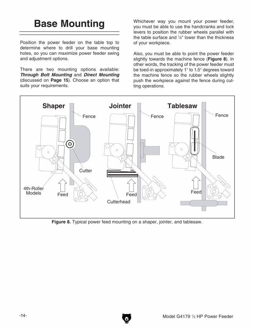
Position the power feeder on the table top to determine where to drill your base mounting holes, so you can maximize power feeder swing and adjustment options.
There are two mounting options available: Through Bolt Mounting and Direct Mounting (discussed on Page 15). Choose an option that suits your requirements.
Whichever way you mount your power feeder, you must be able to use the handcranks and lock levers to position the rubber wheels parallel with the table surface and 1⁄8" lower than the thickness of your workpiece.
Also, you must be able to point the power feeder slightly towards the machine fence (Figure 8). In other words, the tracking of the power feeder must be toed-in approximately 1° to 1.5° degrees toward the machine fence so the rubber wheels slightly push the workpiece against the fence during cut-ting operations.
Feed Feed
TablesawShaper
Cutter
Feed
Jointer
Cutterhead
Blade
Fence Fence Fence
4th-RollerModels
Figure 8. Typical power feed mounting on a shaper, jointer, and tablesaw.
Base Mounting

Model G4179 1⁄2 HP Power Feeder -15-
To correctly position this power feeder on your table top, completely assemble the power feeder first, then refer to this section and mount your base to the table using one of the two methods below. The reason for this order is that with the power feeder unit completely assembled, it will be easier to locate where on the table top you will need to drill your base mounting holes, so you can take advantage of the full range of power feeder swing and adjustments.
Through-Bolt Mounting We recommend that you mount your new power feeder to the machine table with through bolts, nuts, and washers (Figure 9). This option will give the most rigidity and clamping strength to prevent the feeder base from twisting out of align-ment during use. However, if under-table support webs interfere with washer or nut locations under the table, you must use an optional clamping kit, or drill and thread holes directly into the table as described in Direct Mounting.
Direct MountingUse the included mounting template to drill and tap your table, so the power feeder base can be directly mounted to the table surface (Figure 10). If the table is thinner than 3⁄8" thick where the threaded holes would be drilled and tapped, or if support webbing is in the way, the threads may strip or loosen as the power feeder is used. Thread locking compound will not cure this situ-ation. Revert to the Through-Bolt Mounting option. In any case, make sure to use a medium-grade liquid thread locking compound on all threads.
Figure 9. Through-bolt mounting.
Machine Table
Flat Washer
Flat WasherLock Washer
Locking Hex NutTableSupport Webbing
BoltFeederBase
Figure 10. Direct mounting.
Machine Table
TableSupport Webbing
BoltFeederBase
Lock WasherFlat Washer
Apply MediumGrade Thread Locking Compound to the Threads
Mounting Options

-16- Model G4179 1⁄2 HP Power Feeder
Test Run
Loose hair, clothing, or jewelry could get caught in machinery and cause serious personal injury. Keep these items away from moving parts at all times to reduce this risk.
To test run the power feed:
1. Read the entire instruction manual first!
2. Make sure all tools and foreign objects have been removed from the tabletop area.
3. Make sure that the power feeder gearbox oil level is full, the oil level should be 1" below the oil fill port. See Figure 1 on Page 5 for oil fill port location.
4. Ensure that all tools and objects used during set up are cleared away from the machine.
5. Adjust and lock the power feeder so the wheels are held approximately one inch above the table and nothing will interfere with wheel rotation.
6. Connect the power feeder to the power sup-ply and use the feed direction switch (Figure 11) to test operation in both directions.
— Listen and watch for abnormal noises or vibrations. The power feeder should run smoothly.
— Correct for any unusual noises or vibra-tions before operating the power feeder any further. Always disconnect the power feeder from power when investigating or correcting potential problems.
Once power feeder assembly is complete and mounted on the table, you must test run your power feeder to make sure it runs properly.
If, during the test run, you cannot easily locate the source of an unusual noise or vibration, stop using the power feeder immediately, then review the Troubleshooting table on Page 21.
If you still cannot remedy a problem, contact our Technical Support at (570) 546-9663 for assis-tance.
Figure 11. Feed direction switch.

Model G4179 1⁄2 HP Power Feeder -17-
SECTION 4: OPERATIONS
Operation Safety
Damage to your eyes and lungs could result from using woodworking machinery without proper protective gear. Always wear safety glasses and a respirator when operating this machine.
NOTICEIf you have never used this type of machine or equipment before, WE STRONGLY REC-OMMEND that you read books, trade maga-zines, or get formal training before begin-ning any projects. Regardless of the con-tent in this section, Grizzly Industrial will not be held liable for accidents caused by lack of training.
Loose hair, clothing, or jewelry could get caught in machinery and cause serious personal injury. Keep these items away from moving parts at all times to reduce this risk.
To reduce the risk of serious injury when using this machine, read and understand this entire manual before beginning any operations.
Basic Use and Care
Power feeders reduce kickback hazards and improve cutting results by feeding in a consistent and stable manner. Remember, do not to stand in the path of potential kickback.
When not in use, support the power feeder with a wooden block so the rubber wheels are raised above the table and do not compress from the weight of the power feeder.
The universal joints on this power feeder allow you to adjust the power feeder tracking and height to accommodate many workpiece sizes. Before loosening any lock lever, always support the power feeder with a block of wood, so the power feeder does not drop and cause damage.
Adjust the power feeder so it is toed-in approxi-mately 1° to 1.5° degrees towards the machine fence. This adjustment will ensure that the power feeder wheels slightly push the workpiece against the fence during cutting operations (Figure 8).
Next, adjust the power feeder so the rubber wheels are parallel with the table surface, and are 1⁄8" lower than the thickness of your workpiece. This adjustment ensures that the workpiece will not slip or hang in the middle of a cut. Always double check that the power feeder wheels are 1⁄8" lower than the workpiece before you begin feed-ing operations. Otherwise, the workpiece may slip and kickback.
You MUST assemble all guards, fences, and hold-downs before starting your machine or power feeder. Failure to heed this warning could result in amputation or death!

-18- Model G4179 1⁄2 HP Power Feeder
4. Remove the chain cover and the two 14mm hex nuts securing the position A & B change gears to the shafts.
5. Swap the required gears in positions A & B shown in Figure 12.
Figure 12. Change gear locations.
6. Reinstall the hex nuts and the chain cover.
Your power feeder has the option to feed a workpiece at four different feed rates: 9.5, 15, 25, and 38 feet per minute. These rates are achieved by changing the combination of change gears in the power feeder gear box.
Always disconnect power to the machine before performing maintenance. Failure to do this may result in serious person-al injury.
Installed Change Gears: A, 20 Tooth + B, 40 Tooth = 9.5 Ft (2.9
M)/Per Min A, 40 Tooth + B, 20 Tooth = 38 Ft (11.6
M)/Per Min
Included Accessory Change Gears: A, 26 Tooth + B, 34 Tooth = 15 Ft (4.6
M)/Per Min A, 34 Tooth + B, 26 Tooth = 25 Ft (7.6
M)/Per Min
To change the feed rate of your power feeder:
1. Turn the speed dial to the OFF position.
2. DISCONNECT THE POWER FEEDER FROM POWER!
3. Refer to the change gear chart below to find the gear combination required for your cho-sen feed rate.
Changing Feed Speed
Position BPosition A
Included Accessory ChangeGear Set (26-34 Tooth)
Model G4179 1⁄2 HP Power Feeder -19-
SECTION 5: MAINTENANCE
For optimum performance from your machine, follow this maintenance schedule and refer to any specific instructions given in this section.
Daily Check:• Loose mounting bolts.• Worn switch.• Worn or damaged cords and plugs.• Damaged wheel rubber.• Any other condition that could hamper the
safe operation of this machine.
Schedule
Always disconnect power to the machine before performing maintenance. Failure to do this may result in serious person-al injury.
Frequently blow-off sawdust with compressed air. This is especially important for the internal working parts and motor. Dust build-up around the motor is a sure way to decrease its life span. If the wheels become loaded up with pitch, oil, or other residues, wipe them clean using a clean rag and a mild solvent. Avoid touching the plastic or paint with mineral spirits or you may damage the surfaces.
Cleaning
• As required to prevent rust, binding, and dry spots, brush the sprockets, chain, and change gears (Figure 14) with a light film of an automotive grade GL-2 grease.
• To prevent surface rust and binding, peri-odically clean and oil all lock lever and lead screw threads with a light machine oil.
Lubrication
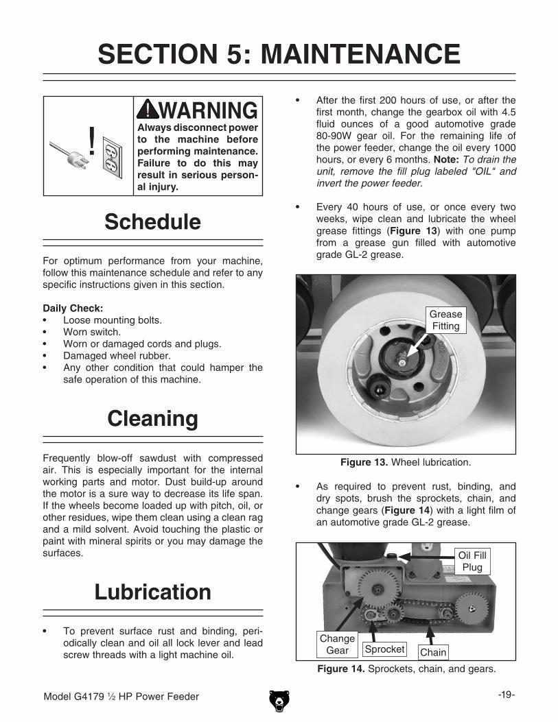
• After the first 200 hours of use, or after the first month, change the gearbox oil with 4.5 fluid ounces of a good automotive grade 80-90W gear oil. For the remaining life of the power feeder, change the oil every 1000 hours, or every 6 months. Note: To drain the unit, remove the fill plug labeled "OIL" and invert the power feeder.
• Every 40 hours of use, or once every two weeks, wipe clean and lubricate the wheel grease fittings (Figure 13) with one pump from a grease gun filled with automotive grade GL-2 grease.
Figure 13. Wheel lubrication.
Grease Fitting
Figure 14. Sprockets, chain, and gears.
ChainSprocketChange
Gear
Oil Fill Plug

-20- Model G4179 1⁄2 HP Power Feeder
Review the troubleshooting and procedures in this section to fix or adjust your machine if a problem devel-ops. If you need replacement parts or you are unsure of your repair skills, then feel free to call our Technical Support at (570) 546-9663.
SECTION 6: SERVICE
Troubleshooting
Motor & Electrical
Symptom Possible Cause Possible SolutionMotor will not start. 1. Low voltage.
2. Open circuit in motor or loose connections.
3. Blown fuse tripped circuit breaker.
4. Capacitor at fault.5. Motor switch or motor is at fault.
1. Check power supply for proper voltage.2. Inspect all lead connections on motor and circuit
board for loose or open connections.3. Repair for cause of overload and replace fuse or
reset circuit breaker.4. Replace capacitor.5. Replace switch, or motor.
Fuses or circuit breakers trip.
1. Short circuit in line cord or plug.
2. Short circuit in motor or loose connections.
3. Power feeder rollers are jammed.
1. Inspect cord or plug for damaged insulation and shorted wires and replace extension cord.
2. Inspect all connections on motor for loose or shorted terminals or worn insulation.
3. Disconnect all machinery from power and correct for cause of jamming.
Motor overheats. 1. Motor overloaded.2. Air circulation through the motor restricted.
1. Reduce power feeder feed rate.2. Clean out motor fan cover to provide normal air
circulation.
Workpiece jams when feeding under rollers.
1. Rollers set too low. 2. Feeder at wrong angle.
1. Raise feeder.2. Adjust angle.
Workpiece slips while passing beneath rollers.
1. Rollers positioned too high, no traction.2. Feeding too fast.3. Rollers are dirty or oily.4. Worn roller(s).
1. Lower feeder.2. Slow feed speed.3. Clean roller surface with a mild solvent.4. Replace roller(s) (Page 21).
Workpiece cut is burnt.
1. Wrong feed speed.2. Cutter is at fault.
1. Adjust feed speed.2. Sharpen or replace dull blade or cutter.
Rough finish or chipped grain on workpiece.
1. Feed speed too fast. 2. Dull cutter or blade.3. Power feeder angle is not toed in to keep
workpiece against the fence.
1. Slow speed. 2. Replace with sharp cutter or blade. 3. Adjust power feeder so it is toed-in 1° to 1.5°
toward the fence.
Fuzzy grain occurs when planing or moulding.
1. Lumber has high moisture content.
2. Dull knives/cutter.
1. If moisture content is higher than 20%, sticker and allow to dry.
2. Sharpen or replace knives.
Workpiece hangs and does not enter the machine.
1. Power feeder roller height is set incorrectly. 1. Lower the power feeder roller 1⁄8" lower than the height of the workpiece.

Model G4179 1⁄2 HP Power Feeder -21-
Wheel Replacement
Figure 15. Wheel replacement.
Cap Screw
2. Using a 5mm hex wrench, remove the two wheel retaining cap screws (Figure 15).
3. Swap the old wheel with the new.
4. Reinstall the two cap screws, and tighten in an alternating pattern until the wheel is sec-cure.
If you damage one or more wheels or they are worn out, you can easily replace the wheels.
Tools Needed QtyHex Wrench 5mm .............................................. 1
To replace a wheel:
1. DISCONNECT THE POWER FEEDER FROM POWER!
Always disconnect power to the machine before performing maintenance. Failure to do this may result in serious person-al injury.

-22- Model G4179 1⁄2 HP Power Feeder
These pages are current at the time of printing. However, in the spirit of improvement, we may make changes to the electrical systems of future machines. Study this diagram carefully. If you notice differences between your machine and these wiring diagrams, call Technical Support at (570) 546-9663 for assistance.
SECTION 7: WIRING
Electrical Safety Instructions1. CIRCUIT REQUIREMENTS. You MUST fol-
low the CIRCUIT REQUIREMENTS given on Page 9. If you are unsure about the wiring codes in your area or you plan to connect your machine to a shared circuit, consult a qualified electrician.
2. SHOCK HAZARD. Disconnect the power from the machine before servicing electrical components. Touching electrified parts will result in personal injury including but not lim-ited to severe burns, electrocution, or death.
3. MOTOR WIRING. The motor wiring shown in these diagrams are current at the time of printing, but it may not match your machine. Always use the wiring diagram inside the motor junction box.
4. EXPERIENCING DIFFICULTIES. If at any
time you are experiencing difficulties under-standing the information included in this sec-tion, contact our Technical Support at (570) 546-9663.
NOTICEThe photos and diagrams included in this section are best viewed in color. You can view these pages in color at www.grizzly.com.

Model G4179 1⁄2 HP Power Feeder -23-READ ELECTRICAL SAFETY ON PAGE 22!
Wiring Diagram
Figure 16. Motor power and direction switch.
Figure 17. Motor capacitors.
Model G4179 Power Feeder Wiring Diagram
R 2 V 1
6 5
Y 10 9
V 3 S 4
7 X 8
11 12
Side A Side B
Motor Power andDirection Switch
Ground
Ground
RunCapacitor
220VMotor
31
8
StartCapacitor
25M
FD
250V
AC
200M
FD
125V
AC
Hot
Hot 6-15 Plug(As Recommended)
220VAC
G
Ground

-24- Model G4179 1⁄2 HP Power Feeder
580
581
581
581
516
515
504
522518
520518
503
525-3501514
513
512511
517
526
525-1
525-2V2
542
539
519
521
525-2V2
516
515
526
525-1
504
512511
517 513514
507525-3
508506
532
520518
508506
541
519576
540
556-2 523524
543
531
545544
534550-1
550-2
550-3
519535-3
535-2535-1
530
515
516
526504
525-1
525-2V2
511
512 525-3507
514513
559-1559-2
576521
546
556-1524
533
549
567569
564
550-4
562
563
517
578
577
502
570
571
575
573
572
535
568
525V2
559
556
550
579
579
579
580
580
564-2 564-3
564-1
564-4
574
SECTION 8: G4179 PARTS
Power Feed

Model G4179 1⁄2 HP Power Feeder -25-
REF PART # DESCRIPTION REF PART # DESCRIPTION501 P4179501 GREASE FITTING M6-1 STRAIGHT 543 P4179543 WORM GEAR502 P4179502 SPROCKET CASE 544 P4179544 WORM GEAR SHAFT503 P4179503 TORSION SPRING (A) 3.5 x 100 545 P4179545 KEY 6 X 6 X 12504 P4179504 CASE COVER 546 P4179546 FLAT WASHER 12MM506 P4179506 GREASE FITTING M6-1 STRAIGHT 549 P4179549 KNOB507 P4179507 CASE SPROCKET 550 P4179550 GEARBOX ASSEMBLY508 P4179508 TORSION SPRING (B) 3.5 X 100 550-1 P4179550-1 GASKET511 P4179511 ROLLER BASE 550-2 P4179550-2 COVER512 P4179512 SPROCKET 550-3 P4179550-3 OIL SEAL513 P4179513 LOCK WASHER 5MM 550-4 P4179550-4 CAP SCREW M6-1 X 16514 P4179514 CAP SCREW M5-.8 X 16 556 P4179556 GEAR SET 20T, 40T515 P4179515 LOCK WASHER 8MM 556-1 P4179556-1 GEAR 20T516 P4179516 CAP SCREW M8-1.25 X 25 556-2 P4179556-2 GEAR 40T517 P4179517 CHAIN-(22S) 559 P4179559 GEAR SET 26T, 34T518 P4179518 TUBE 559-1 P4179559-1 GEAR 34T519 P4179519 EXT RETAINING RING 24MM 559-2 P4179559-2 GEAR 26T520 P4179520 SPROCKET SHAFT 562 P4179562 OIL CAP521 P4179521 EXT RETAINING RING 13MM 563 P4179563 O-RING 15.8 X 2.4 P16522 P4179522 SPROCKET SHAFT 564 P4179564 MOTOR 1/2HP 110V523 P4179523 FLAT WASHER 12MM 564-1 P4179564-1 FAN524 P4179524 HEX NUT M12-1.75 564-2 P4179564-2 FAN COVER525V2 P4179525V2 SPINDLE ASSEMBLY 564-3 P4179564-3 R. CAPACITOR 25MFD 250VAC525-1 P4179525-1 GREASE FITTING M6-1 STRAIGHT 564-4 P4179564-4 S. CAPACITOR 200MFD 125VAC525-2V2 P4179525-2V2 ROLLER SPINDLE V2.06.14 567 P4179567 COMPLETE SWITCH ASSEMBLY525-3 P4179525-3 FLAT WASHER 12MM 568 P4179568 SPACER W/SEAL526 P4179526 ROLLER 569 P4179569 COMPLETE SWITCH BOX ASSEMBLY530 P4179530 HOUSING 570 P4179570 QC LABEL531 P4179531 BUSHING 571 P4179571 GENERAL WARNING LABEL532 P4179532 SET SCREW M6-1 X 10 572 P4179572 COVER WARNING LABEL533 P4179533 GEAR COVER 573 P4179573 GRIZZLY LOGO PLATE534 P4179534 BALL BEARING 6203ZZ 574 P4179574 SWITCH DIRECTION LABEL535 P4179535 SWIVEL CONE ASSEMBLY 575 P4179575 ELECTRICITY LABEL535-1 P4179535-1 CONE 576 P4179576 SPROCKET535-2 P4179535-2 LOCK WASHER 8MM 577 P4179577 LOCK WASHER 6MM535-3 P4179535-3 CAP SCREW M8-1.25 X 25 578 P4179578 HEX BOLT M6-1 X 30539 P4179539 SPROCKET 579 P4179579 HEX BOLT M12-1.75 X 50540 P4179540 SPACING COLLAR 580 P4179580 SPACER541 P4179541 CHAIN (36S) 581 P4179581 EXT RETAINING RING 17MM542 P4179542 CHAIN (22S)
Power Feed Parts List

-26- Model G4179 1⁄2 HP Power Feeder
REF PART # DESCRIPTION REF PART # DESCRIPTION656V2 P4179656V2 ELEVATING BRACKET ASSEMBLY 664 P4179664 HANDLE656-1 P4179656-1 ELEVATING BRACKET 673V2 P4179673V2 BASE ASSEMBLY656-3 P4179656-3 FLAT WASHER 1/2 673-1 P4179673-1 COLUMN BASE656-4 P4179656-4 HANDLE 673-3 P4179673-3 FLAT WASHER 1/2657 P4179657 ELEVATION LEAD SCREW 673-4 P4179673-4 LEVER658 P4179658 HORIZONTAL LEAD SCREW 678 P4179678 VERTICAL COLUMN ASSEMBLY659 P4179659 COLUMN CAP 678-1 P4179678-1 COLUMN660 P4179660 SET SCREW M8-1.25 X 12 678-2 P4179678-2 KEY 350MML X 8T662 P4179662 OVER ARM CONE ASSEMBLY 678-3 P4179678-3 CAP SCREW M5-.8 X 10662-1 P4179662-1 OVER ARM CONE 682 P4179682 OVER ARM ASSEMBLY662-2 P4179662-2 LOCK STUD 682-1 P4179682-1 OVER ARM662-3 P4179662-3 T-HANDLE 682-2 P4179682-2 KEY 564MML X 8T662-4 P4179662-4 ROLL PIN 6 X 22 682-3 P4179682-3 CAP SCREW M5-.8 X 8662-5 P4179662-5 FLAT WASHER 1/2 683 P4179683 ROLL PIN 6 x 36662-6 P4179662-6 CAP SCREW M12-1.75 X 50 684 P4179684 HEX WRENCH 4MM663 P4179663 SWIVEL CONE ASSEMBLY 685 P4179685 CRANK ARM663-1 P4179663-1 SWIVEL CONE 686 P4179686 HEX BOLT M12-1.75 X 70663-2 P4179663-2 LOCK STUD 687 P4179687 LOCK WASHER 12MM663-3 P4179663-3 T-HANDLE 688 P4179688 HEX BOLT M12-1.75 X 50663-4 P4179663-4 ROLL PIN 6 X 22
Stand
656-4
656-3
660
685 683664
659
683660
664
685
659656-1
673-4 673-3
686
688
687673-1
658
657656-4
656-3
662-5
662-6
662-3
662-4
662-2
663-2663-1
663-3
663-4662-1
687686
687
686
687
682-3
684
682682-1
682-2
673V2
678-3678-1678-2
678
656V2
662
663

CU
T A
LON
G D
OT
TE
D L
INE
Name _____________________________________________________________________________
Street _____________________________________________________________________________
City _______________________ State _________________________ Zip _____________________
Phone # ____________________ Email _________________________________________________
Model # ____________________ Order # _______________________ Serial # __________________
WARRANTY CARD
The following information is given on a voluntary basis. It will be used for marketing purposes to help us develop better products and services. Of course, all information is strictly confidential.
1. How did you learn about us? ____ Advertisement ____ Friend ____ Catalog ____ Card Deck ____ Website ____ Other:
2. Which of the following magazines do you subscribe to?
3. What is your annual household income? ____ $20,000-$29,000 ____ $30,000-$39,000 ____ $40,000-$49,000 ____ $50,000-$59,000 ____ $60,000-$69,000 ____ $70,000+
4. What is your age group? ____ 20-29 ____ 30-39 ____ 40-49 ____ 50-59 ____ 60-69 ____ 70+
5. How long have you been a woodworker/metalworker? ____ 0-2 Years ____ 2-8 Years ____ 8-20 Years ____20+ Years
6. How many of your machines or tools are Grizzly? ____ 0-2 ____ 3-5 ____ 6-9 ____10+
7. Do you think your machine represents a good value? _____Yes _____No
8. Would you recommend Grizzly Industrial to a friend? _____Yes _____No
9. Would you allow us to use your name as a reference for Grizzly customers in your area? Note: We never use names more than 3 times. _____Yes _____No
10. Comments: _____________________________________________________________________
_________________________________________________________________________________
_________________________________________________________________________________
_________________________________________________________________________________
____ Cabinetmaker & FDM____ Family Handyman____ Hand Loader____ Handy____ Home Shop Machinist____ Journal of Light Cont.____ Live Steam____ Model Airplane News____ Old House Journal____ Popular Mechanics
____ Popular Science____ Popular Woodworking____ Precision Shooter____ Projects in Metal____ RC Modeler____ Rifle____ Shop Notes____ Shotgun News____ Today’s Homeowner____ Wood
____ Wooden Boat____ Woodshop News____ Woodsmith____ Woodwork____ Woodworker West____ Woodworker’s Journal____ Other:

TAPE ALONG EDGES--PLEASE DO NOT STAPLE
FOLD ALONG DOTTED LINE
FOLD ALONG DOTTED LINE
GRIZZLY INDUSTRIAL, INC.P.O. BOX 2069BELLINGHAM, WA 98227-2069
PlaceStampHere
Name_______________________________
Street_______________________________
City______________State______Zip______
Send a Grizzly Catalog to a friend:

WARRANTY AND RETURNS
Grizzly Industrial, Inc. warrants every product it sells for a period of 1 year to the original purchaser from the date of purchase. This warranty does not apply to defects due directly or indirectly to misuse, abuse, negligence, accidents, repairs or alterations or lack of maintenance. This is Grizzly’s sole written warranty and any and all warranties that may be implied by law, including any merchantability or fitness, for any par-ticular purpose, are hereby limited to the duration of this written warranty. We do not warrant or represent that the merchandise complies with the provisions of any law or acts unless the manufacturer so warrants. In no event shall Grizzly’s liability under this warranty exceed the purchase price paid for the product and any legal actions brought against Grizzly shall be tried in the State of Washington, County of Whatcom.
We shall in no event be liable for death, injuries to persons or property or for incidental, contingent, special, or consequential damages arising from the use of our products.
To take advantage of this warranty, contact us by mail or phone and give us all the details. We will then issue you a “Return Number,’’ which must be clearly posted on the outside as well as the inside of the carton. We will not accept any item back without this number. Proof of purchase must accompany the merchandise.
The manufacturers reserve the right to change specifications at any time because they constantly strive to achieve better quality equipment. We make every effort to ensure that our products meet high quality and durability standards and we hope you never need to use this warranty.
Please feel free to write or call us if you have any questions about the machine or the manual.
Thank you again for your business and continued support. We hope to serve you again soon.
WARRANTY AND RETURNS