model g5ct counter top operation manual
TRANSCRIPT

1 | P a g e
MODEL G5CT COUNTER TOP OPERATION MANUAL

2 | P a g e
Table of Contents Introduction…….……………………………………………………………………………………..pg.3 Receiving………….…………………………………………………………………………………….pg.4 Description Model G5CT Counter Top………………..………………..………………...pg.5 Operation……………………………….……………………………………………………………pg.6,7 Positioning the Cooler………………….……………………………………………….…….….pg.8 Water Cooler Connections…………….………………………………………….…….........pg.9 Feed Water Connection……………….……………………………………………………….pg.10 Drain Connection……………………….…………………………………………………………pg.11 EZ Connections………………………….………………………………………………………….pg.12 Start Up Flush……………………………………………………………………………............pg.13 Tank Flush…………………………………………………………………………………………….pg.14 Cleaning and Maintenance…………….………………………………………….………….pg.15 Sanitization …………………………………………………………………………………........p.g.16 Filter Replacement………………………….……………………………………………….…..pg.17 Reverse Osmosis Membrane Replacement.…………………………………….……pg.18 Troubleshooting……………………………………….………………………………………....pg.19 Specifications………………………………………….………………………………………..….pg.20 Warranty……………………………………………………….……………………………………..pg.21
List of Figures Figure 1. Assembly Drawing, Model G5CT………………...….…………….………….pg.5 Figure 2. Faucet Operation…………………………….….………..………………………….pg.6 Figure 3. Hot/Cold Power On/Off Switch.……….….……………..……………………pg.6 Figure 4. Water Cooler Connections………………...…………………..………………..pg.9 Figure 5. Drain Connections for “RO” Models……………………………….……...pg.11 Figure 6. Filter Configuration Model “F”……………………………………………….pg.13 Figure 7. Back View of Coolers………………………….…………………………………..pg.14 Figure 8. RO Membrane Installation………………….………………………………….pg.18

3 | P a g e
Introduction
Congratulations on your purchase of our revolutionary Bottle-less Water Cooler! Our coolers are all designed to replace the conventional 5 gallon water bottle while eliminating the hassles of deliveries, lifting bottles and eliminating plastic bottles from landfills. Our coolers are designed to produce pure great tasting water for the whole family that is clean and safe to drink. Our coolers are connected to your city or well water supply to efficiently filter out tastes and odor, and to remove microscopic contaminants by using reverse osmosis purification technology. We manufacture a wide range of models to fit any home or office application. The G5CT Counter Top has 3 temperature faucets; cold water is chilled around 44ºF, hot water is heated at 180ºF and ambient. All Global Water models are manufactured and marked as “RO” or “F” assemblies. The “RO” assembly utilizes CSM Reverse Osmosis water purification technology which produces pure safe water from city or well water. The “RO” assembly is comprised of a 5-micron sediment filter, a carbon (GAC) 10-micron filter, CSM RO membrane and a post carbon filter to improve taste. The “RO” filter assembly requires a drain line connection to be installed which removes rejected water to the sewer. The “F” assembly is comprised of sediment and carbon filter system, but not the RO membrane; therefore, it does not require a drain line connection. CAUTION: The filter version “F” must be used only with softened water or water that has less than 3.5-grains of hardness to prevent scaling and premature burnout of the heating elements. Please read all the instructions in this manual before operating this unit.

4 | P a g e
Receiving the Cooler Unpacking Global Water products are shipped completely assembled and ready to operate. Remove the top of the box and slide the water cooler out and save the box and packing materials. Inspection Inspect the cooler for shipping damage. Look at the exterior panels to see if they have been dented or damaged. Check the dispensing spigots in the front. Open the bottom panel to assure that the filter system is intact. Look at the back of the cooler to see if the compressor is secure and has not broken from the mounting. Inspect filter system to see that nothing is damaged or dislodged from shipping. Description Model G5CT The G5CT Model provides water at 3 different temperatures, dispensed from three spigots, “hot”, “cold” and ambient. The assembly drawing is shown in Figure 1. Water flows from the filter system into the ambient tank and the cold water tank simultaneously. The cold tank then feeds the hot tank which is heated by internal heaters. The level in the cold water tank is controlled by a float valve mechanism which controls a 4 way auto-shut off valve on the water feed line to maintain a constant level of filtered water. Both models are available with reverse osmosis (RO) or standard filter (F) versions.

5 | P a g e
Description Model G5CT Counter Top
Figure 1. Assembly Drawing Model G5CT Counter Top
6 | P a g e
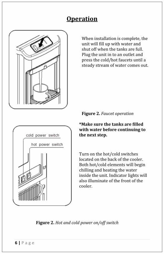
Operation When installation is complete, the unit will fill up with water and shut off when the tanks are full. Plug the unit in to an outlet and press the cold/hot faucets until a steady stream of water comes out. Figure 2. Faucet operation
*Make sure the tanks are filled with water before continuing to the next step.
Turn on the hot/cold switches located on the back of the cooler. Both hot/cold elements will begin chilling and heating the water inside the unit. Indicator lights will also illuminate of the front of the cooler.
Figure 2. Hot and cold power on/off switch

7 | P a g e
Operation Cont…

8 | P a g e
Positioning the Cooler
1) It is not recommended to install this cooler in an area were water may cause severe or costly damage. 2) Do not position the cooler where it can be hit or bumped by Vacuum cleaners or floor waxing machines. This can cause breaks in the waterline, connection fittings and compressor tubing.
9 | P a g e
Water Cooler Connections
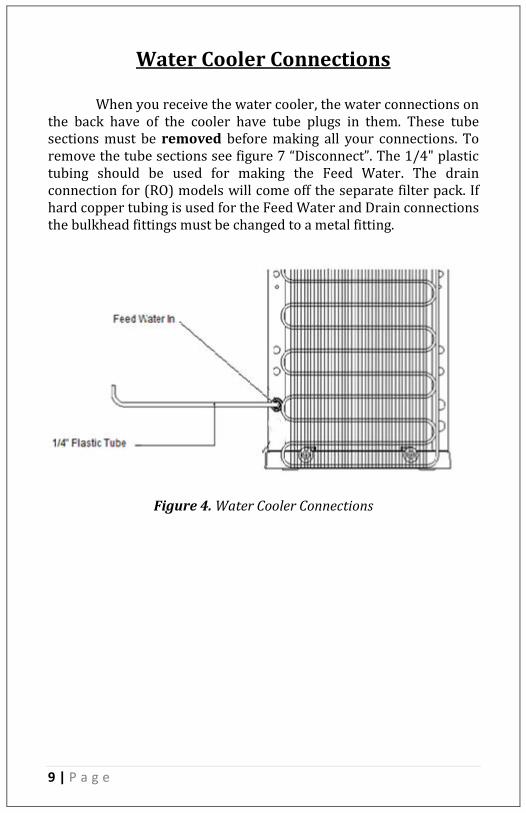
When you receive the water cooler, the water connections on
the back have of the cooler have tube plugs in them. These tube sections must be removed before making all your connections. To remove the tube sections see figure 7 “Disconnect”. The 1/4" plastic tubing should be used for making the Feed Water. The drain connection for (RO) models will come off the separate filter pack. If hard copper tubing is used for the Feed Water and Drain connections the bulkhead fittings must be changed to a metal fitting.
Figure 4. Water Cooler Connections

10 | P a g e
Feed Water Connections
To connect the feed water, use the supplied self-piercing saddle valve to connect to the cold water supply line under the sink.
Attach the 1/4-inch tubing to the compression fitting on the side of
the valve. Clamp the saddle valve over copper or plastic feed line (cold water only). Turn the handle on the valve until the needle stem
pierces the tube. Then retract the needle 1-2 turns to start water flow. See Photo inset.
11 | P a g e
Drain Connection
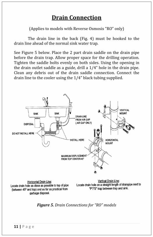
(Applies to models with Reverse Osmosis “RO” only)
The drain line in the back (Fig. 4) must be hooked to the drain line ahead of the normal sink water trap. See Figure 5 below. Place the 2 part drain saddle on the drain pipe before the drain trap. Allow proper space for the drilling operation. Tighten the saddle bolts evenly on both sides. Using the opening in the drain outlet saddle as a guide, drill a 1/4” hole in the drain pipe. Clean any debris out of the drain saddle connection. Connect the drain line to the cooler using the 1/4” black tubing supplied.
Figure 5. Drain Connections for “RO” models
12 | P a g e
EZ Connections
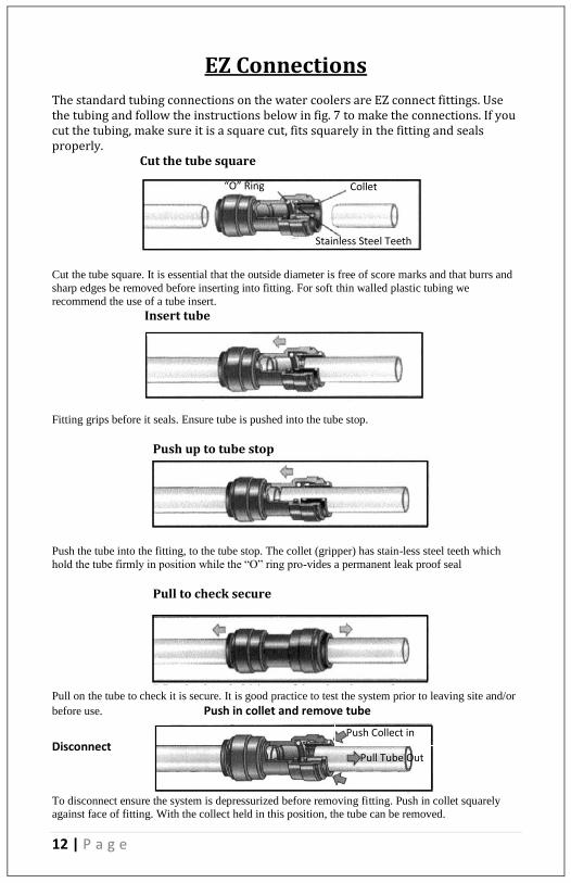
The standard tubing connections on the water coolers are EZ connect fittings. Use the tubing and follow the instructions below in fig. 7 to make the connections. If you cut the tubing, make sure it is a square cut, fits squarely in the fitting and seals properly. Cut the tube square
Cut the tube square. It is essential that the outside diameter is free of score marks and that burrs and
sharp edges be removed before inserting into fitting. For soft thin walled plastic tubing we
recommend the use of a tube insert.
Insert tube
Fitting grips before it seals. Ensure tube is pushed into the tube stop.
Push up to tube stop
Push the tube into the fitting, to the tube stop. The collet (gripper) has stain-less steel teeth which
hold the tube firmly in position while the “O” ring pro-vides a permanent leak proof seal
Pull to check secure
Pull on the tube to check it is secure. It is good practice to test the system prior to leaving site and/or
before use. Push in collet and remove tube
Disconnect
To disconnect ensure the system is depressurized before removing fitting. Push in collet squarely against face of fitting. With the collect held in this position, the tube can be removed.
Push Collect in
Pull Tube Out
“O” Ring Collet
Stainless Steel Teeth

13 | P a g e
Start-Up Flush
If you order our (ro) model you will receive a large white tank and a separate box that containers the filter pack. Unpack both of these and set them up near the cooler. Our (f) models do not have the tank. Now you have to connect the water line to the filter pack which can be found on water feed connections page. When the water runs off the last filter connect one tube to the white tank and the other tube to the back of the cooler. To flush the filters disconnect the tube from the 2nd stage carbon filter (circle in figure below) and place a cup or pan right underneath the hole to catch water. Open ball valve inside the cooler 1/4-turn (handle in line with tube is “on” and let water flow through filters into the bucket or pan
to push out air and carbon fines. When water runs clear, turn off ball valve and re-connect the tube to the filter. Turn on the water to the filter system by opening the ball valve inside the cooler 1/4-turn (handle in line with tube is “on”). Check all connections to assure there are no leaks.
Figure. 6 Filter configuration

14 | P a g e
Tank Flush
Flush tanks out by draining all water through the (1) drain plug located on the back of the cooler and drain water through the dispensing spigots. Fill and empty the tanks 3 times with the filtered water, this ensures great tasting water. When the tank has filled again with filtered water the cooler is ready to dispense water. You may now turn on the Hot and Cold buttons on the back of the machine. NOTE: You should always turn on the Hot and Cold elements when they have water inside the tanks. CAUTION. DO NOT TURN ON HOT OR COLD POWER CONTROLS YET. Remove the top cover of the cooler by removing 2 screws from back of top cover. Pull the cover off, exposing the main tank. This model uses a mechanical float valve to control flow to the tank. The unit does not have to be plugged in to start water flow. Water will flow into the ambient, cold and then the hot tank as well. Let cooler tanks fill with the filtered water until full - about 1-hours for the ‘RO’ version, about 10-15 minutes for the ‘F’ version. Observe the water level when full, and see that water input to the tank stops when it is full.
Figure. 7 Back view of the Cooler Water Connections Model G5CT

15 | P a g e
Cleaning and Maintenance

16 | P a g e
Sanitize
Fill main water tank with water. Add 1-2 teaspoons of liquid chlorine bleach. Let stand for 5-10 minutes. Drain the water then let water from filters refill tank and drain a second time. Remember to drain from dispensing spigots also. Note: Upon completion of cleaning, wait at least 10 minutes after the power cord is plugged in before turning on the Hot and Cold Water buttons.

17 | P a g e
Filter Replacement
The filter elements must be replaced at regular intervals to maintain the quality of the water.
The G5CTF has 3-stages of mechanical filtration. 1st stage 5-micron sediment filter, 2nd stage activated carbon filter and a 3rd stage post carbon filter. The filter elements in all stages must be replaced every 6 months.
The G5CTRO model has the 3-stages of filtration plus an
additional Reverse Osmosis membrane filter. The 3 pre filters must
be replaced every 6 months. The Reverse Osmosis membrane must
be replaced every 3 years.
Replacement Procedures, Filtration Versions (F) G5CTF Coolers
a) TURN OFF POWER TO HOT/COLD ELEMENTS b) Swing open the front hinged cover. c) Close the ball valve to stop water flow through the filters. d) Place a towel under the filters to catch water. The filters will
have water in them which will run out when the filters are unlocked.
e) Twist the filters to remove them from their housings. f) These filters are disposable, encapsulated filters. Remove and
discard the entire filter body. Replacement filters are sold as a set:
1st Stage sediment filter 2nd Stage carbon filter P/N TWSET 3rd Stage post carbon filter
f) Twist new filters on the housing brackets. g) Open ball valve and let water flow through filters, when the
cooler is full empty out the water into a bucket. This will eliminate the first batch of water which is full with carbon fines.
h) After the cooler fills up again turn on the power to the cold and hot tanks. Wait a few minutes to assure there are no leaks and close the filter door.
18 | P a g e
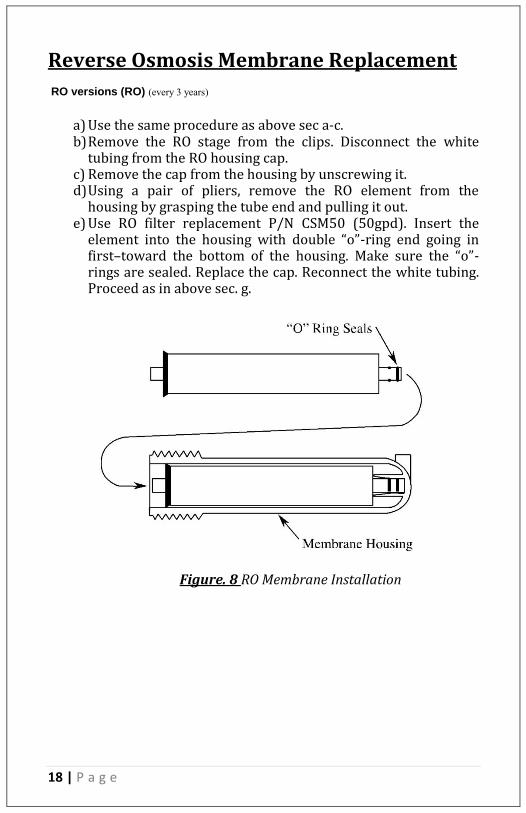
Reverse Osmosis Membrane Replacement RO versions (RO) (every 3 years)
a) Use the same procedure as above sec a-c. b) Remove the RO stage from the clips. Disconnect the white
tubing from the RO housing cap. c) Remove the cap from the housing by unscrewing it. d) Using a pair of pliers, remove the RO element from the
housing by grasping the tube end and pulling it out. e) Use RO filter replacement P/N CSM50 (50gpd). Insert the
element into the housing with double “o”-ring end going in first–toward the bottom of the housing. Make sure the “o”-rings are sealed. Replace the cap. Reconnect the white tubing. Proceed as in above sec. g.
Figure. 8 RO Membrane Installation

19 | P a g e
Trouble Shooting Guide
Note - In the event of problems beyond the scope of the troubleshooting described in the manual, please call your selling dealer.
PROBLEM CAUSE SOLUTION
No Power No electric current
flowing.
Make sure the cooler
is plugged in and
check for improper
connections.
Cold Water not cold
enough
The cooler is placed
too close to the wall.
Wire Condenser on
backside is dusty.
Compressor does not
have enough
refrigerant.
Provide a minimum of
5” space between wall
and back of dispenser.
Clean wire condenser
every three months.
Place cooler in a well-
ventilated area.
Adjust thermostat.
Hot Water doesn’t
flow out of spigot
Air may be trapped in
the line.
Hold the spigot down
for 30 seconds to
relieve air.
Won’t cool Controls not set. Turn cold temperature
switch “on” at back.
Panel not lit No power. Check that the power
cord is in the socket
and turn on the
cold/hot buttons on
the back of the cooler
to the “on” position
No hot water at start
up
Hot tank overheat
protection sensor
tripped.
1. Unplug cooler.
2. Let sensor cool
down for 1 hour.
3. Reach through
cooling grill with
pencil or narrow
screwdriver to press
nude color reset
button on upper sensor
located on the hot
tank.

20 | P a g e
Specifications
Model No. G5CTCT
Voltage/Frequency AC110V
Dimensions (L)14 x (W)13 x (H)19
Weight (empty) 35 lb.
Hot Tank Capacity .5 gal.
Ambient Tank Capacity Direct
Cold Tank Capacity 1 gal.
Power Consumption Hot Water: 500W
Cold Water: 100W
Electric Power Cord Length 6Ft.

21 | P a g e
Warranty
All Global Water products are warranted to be free from defects in materials and workmanship under normal use within the condition of operation listed for a period of 1 year from date of purchase. The compressor has a 3-year warranty.
There is no liability assumed by the company for damage due to water leakage or other secondary effects from any component defect. Labor is not covered in this warranty. The warranty applies when “Conditions of Operation” below are met. Conditions of Warranty
Water System Pressure 35 -100psi, Temperature, 40 -100degrees F, Water PH range 4-10, Max. TDS 1500 PPM, Turbidity, <1.0 NTU, Water Hardness < 20gpg, Iron <0.1 mg/l, Manganese <0.1 mg/l, Hydrogen Sulfide < 0.00 mg/l *For filter only systems (“F” models), water hardness must be less than 3.5 grains or 60 mg/liter

22 | P a g e
Cleaner, Healthier Water.
2031 SW 31st Ave, Hallandale, Florida 33009 www.GlobalWaterInc.com
Tel. (786) 235-2518 Fax (786) 207-2570
Email [email protected]