model gx10/gx20/gp10/gp20/gm10 loop control … 04l51b01-31en v 1 2 3 4 5 6 app index ... 2.3.3...
TRANSCRIPT

User’sManual
IM 04L51B01-31EN1st Edition
Model GX10/GX20/GP10/GP20/GM10
Loop Control Function, Program Control Function (/PG Option)User’s Manual


iIM 04L51B01-31EN
IntroductionThank you for purchasing the SMARTDAC+ GX10/GX20/GP10/GP20/GM10 (hereafter referred to as the GX, GP, or GM).This manual describes the operating procedure for the loop control function and program control function (/PG option) of the GX, GP, and GM. This manual uses GX20 screens to explain the procedures, but the procedures are similar on the GX10, GP10, and GP20.In this manual, the GX20, GP20, and GM10 standard type and large memory type are distinguished using the following notations.• Standard type: GX20-1/GP20-1, GM10-1• Large memory type: GX20-2/GP20-2, GM10-2
To ensure correct use, please read this manual thoroughly before beginning operation.Please use this manual in conjunction with the GX, GP, or GM User’s Manual (GX/GP: IM 04L51B01-01EN, GM: IM 04L55B01-01EN).
Notes● Thecontentsofthismanualaresubjecttochangewithoutpriornoticeasaresultof
continuing improvements to the instrument’s performance and functions.● Everyefforthasbeenmadeinthepreparationofthismanualtoensuretheaccuracyofits
contents. However, should you have any questions or find any errors, please contact your nearest YOKOGAWA dealer.
● CopyingorreproducingalloranypartofthecontentsofthismanualwithoutYOKOGAWA’s permission is strictly prohibited.
Trademarks● SMARTDAC+,andSMARTDACPLUSareregisteredtrademarksofYokogawaElectric
Corporation.● MicrosoftandWindowsareregisteredtrademarksortrademarksofMicrosoftCorporation
in the United States and other countries.● AdobeandAcrobatareregisteredtrademarksortrademarksofAdobeSystems
Incorporated.● KerberosisatrademarkofMassachusettsInstituteofTechnology(MIT).● RC4isaregisteredtrademarkofRSASecurityInc.intheUnitedStatesandother
countries.● Companyandproductnamesthatappearinthismanualareregisteredtrademarksor
trademarks of their respective holders.● Thecompanyandproductnamesusedinthismanualarenotaccompaniedbythe
registered trademark or trademark symbols (® and ™).
About the Usage of Open Source SoftwareThis product uses open source software.For details on using open source software, see Regarding the Downloading and Installing for the Software, Manuals and Labels (IM 04L61B01-11EN).
Revisions1st Edition: June 2017
1st Edition: Jun. 2017 (YK)All Rights Reserved, Copyright © 2017, Yokogawa Electric Corporation

ii IM 04L51B01-31EN
Conventions Used in This ManualUnit
K Denotes 1024. Example: 768K (file size)k Denotes 1000.
NotesImproper handling or use can lead to injury to the user or damage to the instrument. This symbol appears on the instrument to indicate that the user must refer to the user’s manual for special instructions. The same symbol appears in the corresponding place in the user’s manual to identify those instructions. In the manual, the symbol is used in conjunction with the word “WARNING” or “CAUTION.”
WARNING Calls attention to actions or conditions that could cause serious or fatal injury to the user, and precautions that can be taken to prevent such occurrences.
CAUTION Calls attention to actions or conditions that could cause light injury to the user or cause damage to the instrument or user’s data, and precautions that can be taken to prevent such occurrences.
Note Calls attention to information that is important for the proper operation of the instrument.
Reference ItemReference to related operation or explanation is indicated after this mark.Example: section 4.1
Conventions Used in the Procedural ExplanationsBold characters Denotes key or character strings that appear on the screen.
Example: VoltA a # 1 Indicates the character types that can be used.
a symbol, uppercase alphabet,numbers
A
1
lowercase alphabet, #
Procedure Carry out the procedure according to the step numbers. All procedures are written with inexperienced users in mind; depending on the operation, not all steps need to be taken.Explanation gives information such as limitations related the procedure.
Indicates the setup screen and explains the settings.
Explanation
Path
Description

iiiIM 04L51B01-31EN
Recorder Version and Functions Described in This ManualThe contents of this manual correspond to the GX/GP with release number 4 (see the STYLE S number) and style number 2 (see the STYLE H number) and the GM10 with release number 4 (see the STYLE S number) and style number 1 (see the STYLE H number).Edition Product Description1 GX/GP: Version 4.01 and later —
GM: Version 4.01 and later
In order to comply with the relevant standard.To comply with CAN/CSA-IEC 61010-2-201, UL 61010-2-201(CSA NRTL/C), and EN 61010-2-201, make sure that the style numbers of the GX/GP main unit, GM90PS power supply module and GX60 I/O base unit are at least 2.
Notes on the User’s Manual• This user’s manual should be readily accessible to the end users so it can be referred to
easily. It should be kept in a safe place.• This guide is intended for the following personnel; Personnel responsible for normal daily operation of the equipment.• Read the information contained in this manual thoroughly before operating the product.• The purpose of this user’s manual is not to warrant that the product is well suited to any
particular purpose, but rather to describe the functional details of the product.

iv IM 04L51B01-31EN
How to Use This Manual
How to UseRead the GX/GP First Step Guide (IM04L51B01-02EN) or the GM First Step Guide (IM04L55B01-02EN) first to familiarize yourself with the basic operation, and then read this manual. For a description of the communication control command functions and software programs, read the respective manuals.This manual consists of six chapters, and an appendix.Chapter Title and Description1 Functional Description
Provides an overview and describes the features, control functions, applications, and so on.2 Using the Control Function for the First Time
Describes basic configuration, monitoring, and operation when using the control function for the first time using a temperature control example.
3 Configuring the Control FunctionDescribes how to configure the control function, input functions, output functions, alarm functions, and so on.
4 Configuring the Program Control Function (/PG option)Describes how to create program patterns and how to configure the program control function.
5 Performing Operations (Main unit, Web application)Describes loop control and program control operations.
6 Using Network Functions (Ethernet interface)Describes operations using Web application.
— AppendixDescribes function block diagrams and program control worksheets.

vIM 04L51B01-31EN
1
2
3
4
5
6
App
Index
Contents
Introduction ........................................................................................................................................... iHow to Use This Manual ......................................................................................................................iv
Chapter 1 Functional Description1.1 Overview and Features .......................................................................................................1-11.2 Instrument Configuration .....................................................................................................1-21.3 Control Functions ................................................................................................................1-41.4 Program Control Function (/PG option) ...............................................................................1-91.5 Input Function ...................................................................................................................1-121.6 Output Function .................................................................................................................1-151.7 Alarm Function ..................................................................................................................1-161.8 Action Function (Contact Input Switch Function) ..............................................................1-191.9 Control Event Action Function ...........................................................................................1-201.10 Operation Screen ..............................................................................................................1-221.11 PC Software ......................................................................................................................1-251.12 Web Application ................................................................................................................1-271.13 Control Data and I/O Data Acquisition/Recording Function ..............................................1-281.14 Screen Transitions ............................................................................................................1-301.15 Application Examples ........................................................................................................1-32
Chapter 2 Using the Control Function for the First Time2.1 Overview .............................................................................................................................2-12.2 Initial Configuration .............................................................................................................2-22.3 Monitoring and Controlling ................................................................................................2-10
2.3.1 Displaying the Monitoring Screen ........................................................................................2-102.3.2 Changing Target Setpoints ...................................................................................................2-122.3.3 Determining the Optimal PID with Auto-Tuning ....................................................................2-142.3.4 Stopping and Running Operations .......................................................................................2-172.3.5 Switching between Auto and Manual Modes .......................................................................2-192.3.6 Controlling the Control Output in Manual Mode ...................................................................2-21
Chapter 3 Configuring the Control Function3.1 Loop Control Configuration Flowchart .................................................................................3-13.2 Loop Numbers and PID Channel Numbers .........................................................................3-23.3 Configuring the Basic Control Function ...............................................................................3-4
3.3.1 Setting the Control Period ......................................................................................................3-43.3.2 Setting the Control Mode .......................................................................................................3-53.3.3 Setting the Control Type .........................................................................................................3-63.3.4 Setting the PID Control Mode ................................................................................................3-73.3.5 Setting the Target setpoint (SP) ...........................................................................................3-103.3.6 Setting a PID Initial Value (Reference Value) Suitable for Temperature or Pressure/
Flow rate Control ..................................................................................................................3-103.3.7 Setting PID Constants .......................................................................................................... 3-113.3.8 Setting PID Constants (PID for Reference Deviation) ..........................................................3-123.3.9 Setting PID Switching (Zone PID (PV/SP/TSP, SP Number)) ..............................................3-123.3.10 Suppressing Overshoot (Super Function) ............................................................................3-183.3.11 Suppressing Integral Action (Anti-reset windup) ..................................................................3-203.3.12 Adjusting Auto-tuning Operation ..........................................................................................3-213.3.13 Setting the Number of SP Groups to Use (Limiting the Number of Use) .............................3-223.3.14 Setting the Number of PID Groups to Use (Limiting the Number of Use) ............................3-233.3.15 Setting SP Limiter ................................................................................................................3-243.3.16 Enabling the External Remote Input Function (RSP Function) ............................................3-253.3.17 Selecting and Compensating Remote Input .........................................................................3-263.3.18 Changing SP at a Fixed Rate (SP Ramp-Rate Setting Function) ........................................3-283.3.19 Forcing SP to Track PV (PV Tracking) .................................................................................3-31

vi IM 04L51B01-31EN
3.3.20 Forcing SP to Track RSP (SP Tracking) ...............................................................................3-323.3.21 Setting the PID Control Module Action at Power-On (Restart Mode) ...................................3-33
3.4 Configuring the Input Function ..........................................................................................3-343.4.1 Setting the Input Type, Unit, Range, Scale, and Decimal Place ..........................................3-343.4.2 Setting Burnout Detection for Input ......................................................................................3-373.4.3 Setting the Burnout Criteria ..................................................................................................3-383.4.4 Setting the Input Reference Junction Compensation (RJC) ................................................3-393.4.5 Performing Calibration Correction ........................................................................................3-403.4.6 Enabling the External PV Input Function (EXPV Function) ..................................................3-453.4.7 Selecting and Compensating External PV Input (EXPV Function) ......................................3-463.4.8 Setting the Measuring Range to Use for PID Control (Control PV input range) ...................3-473.4.9 Adjusting PV Range for Loop Control with PV Switching (Control PV input range) .............3-493.4.10 Setting PV Switching Methods of Loop Control with PV Switching ......................................3-50
3.5 Configuring the Output Function .......................................................................................3-553.5.1 Setting the Control Output Type (Current output, Voltage pulse output, 15 V DC loop
power supply) .......................................................................................................................3-553.5.2 Setting the Cycle Time of Control Output (Voltage pulse output) .........................................3-563.5.3 Changing the Current Output Range ...................................................................................3-573.5.4 Setting Direct or Reverse Operation ....................................................................................3-593.5.5 Setting Limiters to Control Output ........................................................................................3-603.5.6 Enabling the Output Limiter Function in Manual Mode (Output limiter switch) ....................3-613.5.7 Setting the Velocity Limiter to Control Output ......................................................................3-623.5.8 Reducing 4-20 mA Current Output to 0 mA (Tight Shut Function) .......................................3-633.5.9 Setting the ON/OFF Control Hysteresis ...............................................................................3-643.5.10 Canceling the PV and SP Offset (Manual Reset).................................................................3-653.5.11 Setting the Retransmission Output Type (PV/SP/OUT, PV2/SP2/OUT2), Range, and
Scale ....................................................................................................................................3-663.5.12 Setting the Output Value for STOP Mode (Preset Output) ...................................................3-683.5.13 Setting the Output Value for Input Errors .............................................................................3-703.5.14 Configuring the Split Computation Output Function .............................................................3-713.5.15 Using the 15 V DC Loop Power Supply ...............................................................................3-73
3.6 Configuring the Control Alarm Function ............................................................................3-743.6.1 Setting the Number of Alarms to Use ...................................................................................3-743.6.2 Setting the Alarm Action depending on the Operation Mode ...............................................3-753.6.3 Setting How to Use the DO Terminal (Contact output within module, Alarm, Manual) .........3-763.6.4 Setting the Alarm Type .........................................................................................................3-803.6.5 Setting Alarm Values ............................................................................................................3-843.6.6 Setting Stand-by Actions ......................................................................................................3-853.6.7 Setting Hysteresis on Alarm Action ......................................................................................3-883.6.8 Delaying the Alarm Output (Delay timer) ..............................................................................3-893.6.9 Alarm ACK (Alarm Relay Hold Function and Hold Release Function) .................................3-90
3.7 Configuring the Action Function (Contact Input Function) .................................................3-933.7.1 Setting Actions .....................................................................................................................3-93
3.8 Configuring the Control Event Action Function .................................................................3-983.8.1 Setting the Control Event Action Number, Event, and Action ...............................................3-98
3.9 Configuring the Control Display Function ........................................................................3-1063.9.1 Configuring Control Groups ...............................................................................................3-1063.9.2 Setting the Displayed Contents of Loops ...........................................................................3-1083.9.3 Setting the PID Channel Display ........................................................................................3-1093.9.4 Setting the Background Color ............................................................................................ 3-1163.9.5 Setting the Control Output Operation Type for Manual Mode ............................................ 3-117
3.10 Common Functions on the Main Unit .............................................................................. 3-118
Chapter 4 Configuring the Program Function (recorder option /PG)4.1 Program Control Configuration Flowchart ...........................................................................4-14.2 Notes on Creating Program patterns ..................................................................................4-24.3 Creating Program Patterns .................................................................................................4-34.4 Setting the PID Selection ....................................................................................................4-54.5 Setting the Program Starting Conditions .............................................................................4-64.6 Setting PV Events .............................................................................................................4-104.7 Setting the PV Event Hysteresis ....................................................................................... 4-114.8 Setting Time Events ..........................................................................................................4-124.9 Setting Wait Functions in a Program (Junction Code) ......................................................4-14
Contents

viiIM 04L51B01-31EN
1
2
3
4
5
6
App
Index
4.10 Setting the Operation in Segment Switching (Junction Code) ..........................................4-194.11 Setting the Action at the Start of Program Operation ........................................................4-234.12 Setting the Segment Repetition ........................................................................................4-264.13 Program Pattern End Signal .............................................................................................4-274.14 Editing Program Patterns ..................................................................................................4-284.15 Printing Auto Messages When a Program Is Run or Reset ..............................................4-294.16 Automatically Displaying the Operation Screen at the Start of Program Operation
(GX/GP only) .....................................................................................................................4-304.17 Assigning Event Displays to Groups .................................................................................4-314.18 Program Pattern Examples ...............................................................................................4-32
Chapter 5 Performing Operations (GX/GP main unit)5.1 Monitoring Loop Control ......................................................................................................5-1
5.1.1 Monitoring and Controlling on the Control Group Screen ......................................................5-15.1.2 Loop Operation and Using the loop operation dialog box ......................................................5-65.1.3 Switching the Displayed Group ..............................................................................................5-95.1.4 Showing the Status of All Loops on a Single Screen (Control Overview) ............................5-105.1.5 Displaying the Multi Panel (GX20/GP20 only) .....................................................................5-125.1.6 Listing the Control Log (Control summary) ..........................................................................5-135.1.7 Listing the Log of Alarm Occurrences and Releases (Control alarm summary) ..................5-165.1.8 Viewing and Adjusting PID and Other Control Parameters (Tuning) ....................................5-18
5.2 Using Loop Control ...........................................................................................................5-235.2.1 Setting or Changing the Target setpoint (SP) .......................................................................5-235.2.2 Performing and Canceling Auto-Tuning ...............................................................................5-245.2.3 Adjusting the PID Manually (Manual Tuning) .......................................................................5-295.2.4 Setting or Changing the Target Setpoint Number (SP number) ...........................................5-365.2.5 Setting or Changing the Alarm Setpoint ...............................................................................5-375.2.6 Switching Operation Modes .................................................................................................5-385.2.7 Controlling the Control Output in Manual Mode ...................................................................5-45
5.3 Performing Program Control (recorder option /PG) ...................................................................................................................................5-475.3.1 Selecting a Program Pattern ................................................................................................5-475.3.2 Performing and Canceling Auto-Tuning ...............................................................................5-535.3.3 Adjusting the PID Manually (Manual Tuning) .......................................................................5-535.3.4 Switching Operation Modes .................................................................................................5-545.3.5 Controlling the Control Output in Manual Mode ...................................................................5-685.3.6 Changing the Current Setpoint in Hold Mode ......................................................................5-695.3.7 Changing the Target Setpoint in Hold Mode ........................................................................5-705.3.8 Changing the Remaining Segment Time in Hold Mode .......................................................5-715.3.9 Changing the Program Pattern during Program Operation ..................................................5-775.3.10 Changing the Local Setpoint in Local Mode .........................................................................5-77
5.4 Executing Various Functions .............................................................................................5-785.4.1 Releasing the Alarm Output (Alarm ACK) ............................................................................5-785.4.2 Acknowledging Control Alarms ............................................................................................5-785.4.3 Using, Registering, and Deleting Favorite Screens .............................................................5-795.4.4 Pattern Overview ..................................................................................................................5-805.4.5 Event Display .......................................................................................................................5-805.4.6 Automatically Displaying the Program Operation Screen ....................................................5-81
Chapter 6 Using Network Functions (Ethernet interface)6.1 Monitoring and Controlling Loop Control .............................................................................6-1
6.1.1 Control Monitor Screens ........................................................................................................6-16.1.2 Faceplate Screen and Controller Screen ...............................................................................6-36.1.3 Control Overview Screen .......................................................................................................6-76.1.4 Control Summary Screen .......................................................................................................6-86.1.5 Control Alarm Summary Screen .............................................................................................6-96.1.6 Tuning Screen ......................................................................................................................6-106.1.7 Switching Operation Modes .................................................................................................6-146.1.8 Changing Target Setpoints ...................................................................................................6-176.1.9 Controlling the Control Output in Manual Mode ...................................................................6-18
6.2 Monitoring and Configuring Program Control ....................................................................6-196.2.1 Displaying the Program Selection Screen and Program Operation Screen .........................6-19
Contents

viii IM 04L51B01-31EN
6.2.2 Running and Resetting Program Pattern Operation (PROG, RESET) ................................6-326.2.3 Holding and Releasing the Program Operation ...................................................................6-336.2.4 Changing the Segment Remaining Time in Hold Mode .......................................................6-346.2.5 Changing the Target Setpoint in Hold Mode ........................................................................6-356.2.7 Advancing the Segment .......................................................................................................6-376.2.8 Switching from Program to Local Mode ...............................................................................6-376.2.9 Changing the Local Setpoint in Local Mode .........................................................................6-38
AppendixAppendix 1 Block Diagram ..........................................................................................................App-1Appendix 2 Program Pattern Setting Table .................................................................................App-4Appendix 3 Terminology ............................................................................................................App-12
Contents

1-1IM 04L51B01-31EN
Functional Description
1
2
3
4
5
6
App
Index
1.1 Overview and Features
The GX90UT is a PID control module that connects to a GX/GP main unit, GX60 expandable I/O unit, GM main unit, or GM sub unit.This chapter provides an overview of the main functions. For further details, see chapter 3 and subsequent chapters.
GX90UT PID Control Module
● AsingleGX90UTPIDControlModulecanperformPIDcontrolonuptotwoloops.Itisequipped with two control inputs (PV inputs), two control outputs, eight digital inputs, and eight digital outputs. In addition to single loop control, cascade control and loop control with PV switching are possible. For the control output, you can select current output or voltage pulse for each loop.
● LoopcontrolispossiblebyinstallingthePIDControlModuleintheGX/GP/GM.Controlloops can be monitored and controlled from a control group screen, and adjustments can be made from a tuning screen.
● The/PGoptionoftheGX/GP/GMmainunitenablesprogramcontrolusingprogrampatterns stored in the GX/GP main unit.
● TheGX90UTcontroldatacanbeacquiredandrecordedintheGX/GP/GMmainunit.
Chapter 1 Functional Description

1-2 IM 04L51B01-31EN
1.2 Instrument Configuration
The instrument configuration when PID Control Modules are used is indicated below.
Configuration with Only the GX/GP Main Unit
Standard typePID control module up to 3 units (up to 6 loops)
The maximum number is 2 when the GP10 supply voltage is 12 VDC.
GX10/GP10 main unit only
Standard typePID control module up to 3 units (up to 6 loops)
Large memory typePID control module up to 8 units (up to 16 loops)
GX20/GP20 main unit only
Configuration with the GX/GP Main Unit and Expandable I/O
Expandable I/OUp to six units
GX10/GP10 main unitGX20/GP20 main unit
The number of units used in the system is
Standard type PID control module up to 3 units (up to 6 loops)
Large memory type PID control module up to 10 units (up to 20 loops)
Note• If the system includes digital output modules (GX90YD) or digital input/output modules
(GX90WD) in addition to PID control modules (GX90UT), the maximum total number of these three modules is 10. (large memory type)
• If the main unit’s measurement mode is high speed, dual interval or if the advanced security function is enabled, PID control modules will not work.

1-3IM 04L51B01-31EN
Functional Description
1
2
3
4
5
6
App
Index
GM Single Unit Configuration
Standard type PID control module up to 3 units (up to 6 loops)
Large memory type PID control module up to 5 units (up to 10 loops)
GM10
GM Multi Unit Configuration
GM10
Sub unitsUp to six units
The number of units used in the system is
Standard type PID control module up to 3 units (up to 6 loops)
Large memory type PID control module up to 10 units (up to 20 loops)
Note• If the system includes digital output modules (GX90YD) or digital input/output modules
(GX90WD) in addition to PID control modules (GX90UT), the maximum total number of these three modules is 10. (large memory type)
• If the main unit’s measurement mode is dual interval or if the advanced security function is enabled, PID control modules will not work.
1.2 Instrument Configuration

1-4 IM 04L51B01-31EN
1.3 Control Functions
Control ModeControl modes define the controls that a single PID Control Module can execute. The PID Control Module operates in the following manner by setting the control mode to execute.
Control mode schematic diagram Description
Single loop control
GX90UT
AI1
AO1
PV1
OUT1 OUT2
PV2PID
AI2
AO2
PID
“Single-loop control” provides the basic control function having one control computation unit.A single PID Control Module can perform two single-loop controls.
Cascade controlAI1
AO2
AI2
PID1
PID2
GX90UT
PV1
OUT1
OUT2
PV2SP2
“Cascade control” has two control computation units and provides a control function that executes cascade control from a single PID Control Module.It is a type of control that provides the primary control output as the secondary control SP.
Loop Control with PV Switching
AI1 AI2
AO1
PID
DI
GX90UT
PV1
OUT1
Switching action
“Loop control with PV switching” uses two PV inputs, which are switched according to input contact signals or measurement ranges.
Explanation of SymbolsAI1: analog input 1, AI2: analog input 2PV1: PV input 1 (loop 1 or primary side), PV2: PV input 2 (loop 2 or secondary side)SP1: target setpoint 1 (loop 1 or primary side), SP2: target setpoint 2 (loop 2 or
secondary side)PID1: PID computation 1 (loop 1 or primary side), PID2: PID computation 2 (loop 2 or
secondary side)OUT1: control output1 (loop 1 or primary side), OUT2: control output 2 (loop 2 or
secondary side)AO1: analog output 1, AO2: analog output 2DI: contact input

1-5IM 04L51B01-31EN
Functional Description
1
2
3
4
5
6
App
Index
The three control modes can be applied to the following types of application. Examples of GX20 are described below.
Industrial furnace temperature control (single-loop control)Rich recipe management improves yield.
Furnace
Product B Thyristor
SCRProduct A
Product C Product D Product E Product F
Improves
yieldQuality
improvement
Equipped with eight sets of target setpoints (SPs) and PIDs per loop
Cascade ControlControl targets with extremely long delay between changes in the control output and measurements on the control target or extremely long dead times can be controlled.
4 to 20 mA DC
Primary PV input
Cold water return
Flowmeter
Cold water
RTD
Secondary PV input
Loop Control with PV SwitchingControl input is automatically switched depending on the temperature region.During low temperature, PV input from a thermocouple is used to perform control, and during high temperature, PV input from a radiation thermometer is used to perform control. When a switch occurs from low temperature to high temperature, a thermocouple pull-out signal is output.
PV at high temperature
PV at low temperature
Thermocouple
Control output
Radiation thermometer
TC pull-out signal
Thyristor
SCR
1.3 Control Functions

1-6 IM 04L51B01-31EN
Control TypePID ControlPID control is a general control using the PID control-related parameters. Continuous PID output (current output) or time proportional PID output (voltage pulse output) can be used.
Alarm
Electric furnace
or
GMGX/GP
4 to 20 mA DC
Thyristor
SCR
Thermocouple
• Continuous PID control: Outputs the PID computation result using a current (analog signal) proportional to the PID computation value.
• Time proportional PID control: Outputs the PID computation result using an on/off signal pulse width proportional to the time. The pulse width is output a percentage of the cycle time (control output cycle) using a voltage pulse.
ON/OFF controlON/OFF control compares the SP and PV and outputs an on or off signal according to the positive or negative deviation (PV – SP).Hysteresis can be set in the vicinity of the on/off output operating point to prevent chattering. The output type is voltage pulse output or current output.
Lower-side hysteresis
Upper-side hysteresis
SP
OutputON
ON
OFF
OFF
ON ON
OFF
PV
Upper-side hysteresis
Lower-side hysteresis
SP
Output
(Reverse operation example)
Temperature
1.3 Control Functions

1-7IM 04L51B01-31EN
Functional Description
1
2
3
4
5
6
App
Index
PID Control ModeThere are two PID control modes: standard PID control mode and fixed-point control mode.In standard PID control mode, when the SP is changed, the output corresponding to the deviation is changed immediately. This mode focuses on reaching the setpoint quickly.In fixed-point control mode, sensitive reaction in response to changes in the SP is suppressed. This mode focuses on stable output.The GX90UT automatically selects the optimal control algorithm according to the operation mode status and performs control.
• PV derivative type PID: Because derivative actions work only on the PV, stable control output is possible. Even when the SP is changed significantly, the control output does not change drastically, and the deviation is gradually eliminated.
PV derivative type PID (output bump at SP change)
SP
PV OUT
PV derivative type PID (output bumpless at SP change)
SP
PV OUT
• Deviation derivative type PID: Because derivative actions work on the changes in the control deviation (difference between the PV and SP, quick response is exhibited to changes in the target setpoint. This method is useful when SP trackability is important.
Deviation derivative type PID
SP
PV OUT
Overshoot Suppressing Function (Super function)“Super” function is an overshoot-suppressing function that uses fuzzy logic.When used in combination with the auto-tuning function, the overshoot suppressing function proves effective in the following situations.• When you want to suppress overshoot• When you want to reduce rise time• When there is a great amount of load fluctuation• When the setpoint is changed frequently
Rise time During program operationTimeTimeTime
When disturbed
Tem
pera
ture
Tem
pera
ture
Tem
pera
ture
“Super”: off
“Super”: on “Super”: on “Super”: on
1.3 Control Functions

1-8 IM 04L51B01-31EN
Direct Operation and Reverse OperationThere are two PID control output operation directions: direct and reverse.These define the increase and decrease directions in which the control output changes in response to positive and negative deviation between the SP and PV.
Over-Integration Suppressing Function (Anti-reset windup)If the deviation between the SP and PV continues for a long time, integral action causes the control output to reach the control output high limit and saturate. Because the control output cannot disengage from the saturated state even when the PV exceeds the SP, overshooting can occur. The over-integration suppression function stops the integral action temporarily when the control output reaches the control output high limit.
SP Ramp-Rate Setting FunctionThe SP ramp-rate setting function forces the SP to change at a fixed rate in order to prevent abrupt changes in the SP or change the SP at a constant rate-of-change.
SP Limiter FunctionThe SP limiter function enables high and low limits to be placed on the SP.
Tracking FunctionThe tracking function prevents the setpoint from changing drastically when the operation mode is changed. PV tracking and SP tracking are available.
PV tracking
PV tracking enabled
MAN AUTO MAN AUTO
PV tracking disabled
PV
SP
PV
SP
Time TimeMode switch Mode switch
Follows SP ramp rate
SP tracking
REM → LCL mode switchTime
REM → LCL mode switchTime
SP tracking enabled SP tracking disabled
PV
PV
SP
RSP
SP
RSP
Explanation of SymbolsMAN: manual mode, AUTO: auto modeREM: remote mode, LCL: local mode
1.3 Control Functions

1-9IM 04L51B01-31EN
Functional Description
1
2
3
4
5
6
App
Index
1.4 Program Control Function (/PG option)
Program control is possible on the GX/GP/GM with the /PG option.
PV input
Control output
Device
SCR
Program pattern
Time
Tem
pera
ture
The program operation can be used to change the SP over time according to a preset program pattern.A program pattern consists of several segments.You can create a program pattern by setting the final target setpoint of each segment, segment time, PV events, time events, and so on.
Seg. 1 Seg. 2 Seg. 3 Seg. 4 Seg. 5 Seg. 6
SegmentPID no. 3
SegmentTime
SegmentPID no. 2
SegmentPID no. 1
PV event 1
Time event 1
Time event 2
SegmentPID no. 4
SegmentPID no. 5
SegmentPID no. 6
Time
Setpoint
PV
SSP
Ramp
RampRamp
Soak
Soak
Soak
PV high PV high
On
On
On
On On
On
OnOff
Off Off Off
Off
Off Off Off Off OffOn
PV high PV high PV low PV low
Time event 3
Pattern end
TSP: Final target setpoint
TSP
TSP
TSP
TSP
SegmentTime
SegmentTime

1-10 IM 04L51B01-31EN
Program Control FunctionsWait FunctionThe wait function pauses the progression of a program when the PV cannot follow the SP.
Repeat FunctionThe repeat function repeatedly runs a given segment (consecutive multiple segments also possible) in a program pattern.
Program Operation Pause (Hold Function)The hold function forces the operation of a program pattern to pause when the program is running.
Program Segment AdvanceThe advance function forces a program pattern to transition to the next segment when the program is running.
Event FunctionThe event function can be used to output alarms according to the progression of program pattern operation or turn on or off the contact output after a given time elapses.Time EventThe time event function turns on or off the contact output when a specified time elapses from the start of a segment operation.
PV EventThe PV function outputs alarms according to the progression of program pattern operation. Events operate only within the specified segments.
PID SelectionYou can select zone PID selection, which selects the PID according to the PV or SP, or segment PID section, which selects the PID for each segment.
Local ModeThe local mode function stops program operation and performs fixed-point control.
Creating Program PatternsTo create a program pattern, you set a line graph of target setpoints in each segment using the final target setpoint (TSP) at the end of each segment and the segment time. You set a final target setpoint for each loop. The segment time applies to all loops.
PV
Segment time
Time
n = 1 to 99
Target setpoint of last segment
(Start target setpoint if program just started)
Segment n operation
Final target setpoint
1.4 Program Control Function

1-11IM 04L51B01-31EN
Functional Description
1
2
3
4
5
6
App
Index
Program Operation Start ActionStarting with the Start Target SetpointThe program operation starts according to a pattern created with the target setpoint for starting the operation and the final target setpoint (TSP) of the first segment, regardless of the PV when the operation starts.
Ramp-Prioritized PV StartRamp-prioritized program runs according to the loop specified with the reference loop number.This method determines the start point by comparing the PV at the start of the nth pattern to the program pattern.Other unspecified loops start according to the pattern of the specified nth pattern.
Time-Prioritized PV StartThe program operation starts according to a pattern created with the PV for starting the operation and the final target setpoint (TSP) of the first segment, regardless of the SP when the operation starts.
1.4 Program Control Function

1-12 IM 04L51B01-31EN
1.5 Input Function
PV InputPV input is a universal input to arbitrarily set the type and range for the thermocouple (TC), resistance-temperature detector (RTD), DC voltage and DI.
Current
Voltage pulse
TCmVV
RTD
Range Setting for Temperature Input
Span lower
Measurement input range
−270.0°C 1370.0°C
0.0°C 800.0°CSpan upper
Range
Range and Scale Settings for Voltage Input
Scale lower
Span lower Span upper
1V 5 V (input signal)
0.0m3/h 50.0m3/hScale upper
2V 4V
Measurement input range
Range
Scale
NoteIf you change the PV range or scale, the control setpoint may be changed.It affects the SP, PV range high and low limits, input switching PV high and low limits, remote bias, SP ramp-rate, high and low limit hystereses, and deviation display band.
In addition to the range and scale settings, you can set the control PV input range that determines the actual range of control.Normally, the range and scale values are set.However, if the range and scale settings exceeds 30000, the control PV input range is set within 30000 based on the lower limit.The control PV input range is used particularly during loop control with PV switching.
External PV (EXPV)In place of the analog input of the PID control module itself, an external input channel (input, math, communication) is used for the PV input.The setting range is set to the control PV input range setting range.

1-13IM 04L51B01-31EN
Functional Description
1
2
3
4
5
6
App
Index
Calibration Correction FunctionBias FunctionBias is a function that adds a bias to the PV input and uses the result in the controller display and control. This function is used to finely adjust the values when the values are within the accepted accuracy range but deviate from those of other devices.
Burner
Heating furnace
PV input value + =PV input bias PV value inside the controller
Temperature sensed by thermocouple
Compensation value
Estimated material temperature
Filter FunctionIf the PV input reading fluctuates greatly and the lower digits are difficult to read, a digital filter can be inserted as a buffer. This filter provides a first-order lag calculation, which can remove more noise as the time constant becomes larger. But, making the time constant too large will distort the waveform.
Actual inputWhen the time constant is small
When the time constant is large
InputExample when a 2-s filter is inserted
Example when a 10-s filter is inserted
Illustration of the filter effect
1.5 Input Function

1-14 IM 04L51B01-31EN
Linearizer Approximation, Linearizer Bias, and Correction Factor*Linearizer approximation is used when the input signal and the required measurement signal have a non-linear relationship, for example, when trying to obtain the volume from a sphere tank level.Linearizer bias is used to correct an input signal affected by sensor deterioration.The correction factor is used to set a correction value on the device side and a correction value on the sensor side and manage them.* On models with the /AH option
Remote Input (RSP)The analog input of the PID control module itself or an external input channel (input, math, communication) is used for the remote input (RSP).
Ratio BiasRatio bias computing performs ratio computation and bias addition for remote input.
Digital InputA single PID control module has eight contact inputs. It can be used to switch stop/run, auto/manual, and other operation modes as well as switch setpoint numbers, and switch program pattern numbers.
1.5 Input Function

1-15IM 04L51B01-31EN
Functional Description
1
2
3
4
5
6
App
Index
1.6 Output Function
Control OutputControl output (OUT) is an universal output. You can set the type of output to current pulse or voltage pulse.
Current
Voltage pulse
TCmVV
RTD
Control Output SuppressionControl Output LimiterControl output limiter can be used to set high and low limits on the control output operation range, regardless of the operation mode. Up to eight sets can be set in association with the PID parameters.
Output Velocity LimiterOutput velocity limiter prevents the control output signal from changing suddenly.
Preset OutputPreset output transmits a preset output value for the control output when the operation mode is changed from the operating state to the stopped state. The value can be set in the range of -5.0 to 105.0%.
Input Error Preset OutputInput error preset output transmits a preset output value or 0% or 100% for the control output when an input burnout, A/D conversion error, or the like occurs.
Tight Shut OutputTight shut output fully closes the control valve (output is zero for 4 to 20 mA current output) beyond its positioner dead band. However, in auto mode, the output low limit is set to -5.0%, and the output does not fall to 0.0 mA. In manual mode, tight shut output (approx. 0.0 mA) is achieved.
Retransmission Output (Analog Retransmission)Retransmission output transmits PV, SP, control output (OUT), and the like externally using analog signals.
Current External device
15 V DC Loop Power SupplyWhen the 15 V DC loop power supply is not used for control output or retransmission output, it can be used to supply 15 V DC to 2-wire type transmitters.
Digital OutputA single PID control module has eight contact outputs. They are used for alarm output and status output.

1-16 IM 04L51B01-31EN
1.7 Alarm Function
Alarm TypesThere are 11 control alarm types. The alarm operation varies depending on the contact action (energize or de-energize).
C
Hysteresis
O
Alarm value PV
SP
Hysteresis
PV
O
Alarm value
C
SPAlarm value PV
Hysteresis Hysteresis
OO C
SPPVAlarm value
O
Hysteresis
C
PV high
PV low
SP high limit
SP low limit
Deviation high limit
Deviation low limit
Deviation H/L limits
Deviation within H/L limits
Control output high limit
Control output low limit
PV velocity
* “O” and “C” indicate the relay contact open and close states.
* “O” and “C” indicate the relay contact open and close states.
The following figure is for the energize case.
SPPV
Hysteresis Hysteresis
Alarm value
OC C
SP
O
Alarm value
Hysteresis
C
SP
O
Hysteresis
Alarm value
C
O
Alarm valueOutput value
Hysteresis
C
O
Hysteresis
Alarm value Output value
C
Alarm value
Hysteresis
O
PV
C
C
Hysteresis
O
Alarm value PV
SP
Hysteresis
PV
O
Alarm value
C
SPAlarm value PV
Hysteresis Hysteresis
OC C
SPPVAlarm value
O
Hysteresis
C
SPPV
Hysteresis Hysteresis
Alarm value
O OC
SP
O
Alarm value
Hysteresis
C
SP
O
Hysteresis
Alarm value
C
O
Alarm value
Hysteresis
PV
C
Alarm valueOutput value
Hysteresis
OC
Hysteresis
Alarm value Output value
O C
Alarm type Alarm action (energize) Alarm action (De-energize)
Alarm type Alarm action
PV
Output
An alarm occurs if the velocity exceeds this inclination.
Time
O OC CO
Velocity alarm time setpoint
Velocity alarm value
Velocity alarm value
Velocity alarm time setpoint
Exceeds the velocityExceeds the velocity
Monitors the variation between 2 points by the time interval according to the PV velocity alarm time setpoint (minute.second).

1-17IM 04L51B01-31EN
Functional Description
1
2
3
4
5
6
App
Index
C
Hysteresis
O
Alarm value PV
SP
Hysteresis
PV
O
Alarm value
C
SPAlarm value PV
Hysteresis Hysteresis
OO C
SPPVAlarm value
O
Hysteresis
C
PV high
PV low
SP high limit
SP low limit
Deviation high limit
Deviation low limit
Deviation H/L limits
Deviation within H/L limits
Control output high limit
Control output low limit
PV velocity
* “O” and “C” indicate the relay contact open and close states.
* “O” and “C” indicate the relay contact open and close states.
The following figure is for the energize case.
SPPV
Hysteresis Hysteresis
Alarm value
OC C
SP
O
Alarm value
Hysteresis
C
SP
O
Hysteresis
Alarm value
C
O
Alarm valueOutput value
Hysteresis
C
O
Hysteresis
Alarm value Output value
C
Alarm value
Hysteresis
O
PV
C
C
Hysteresis
O
Alarm value PV
SP
Hysteresis
PV
O
Alarm value
C
SPAlarm value PV
Hysteresis Hysteresis
OC C
SPPVAlarm value
O
Hysteresis
C
SPPV
Hysteresis Hysteresis
Alarm value
O OC
SP
O
Alarm value
Hysteresis
C
SP
O
Hysteresis
Alarm value
C
O
Alarm value
Hysteresis
PV
C
Alarm valueOutput value
Hysteresis
OC
Hysteresis
Alarm value Output value
O C
Alarm type Alarm action (energize) Alarm action (De-energize)
Alarm type Alarm action
PV
Output
An alarm occurs if the velocity exceeds this inclination.
Time
O OC CO
Velocity alarm time setpoint
Velocity alarm value
Velocity alarm value
Velocity alarm time setpoint
Exceeds the velocityExceeds the velocity
Monitors the variation between 2 points by the time interval according to the PV velocity alarm time setpoint (minute.second).
Number of Alarm SetpointsNumber of alarm setpoints: 4 per loop
Alarm HysteresisIf the alarm output repeatedly turns on and off drastically, you can reduce the intensity by increasing the alarm hysteresis.
Standby ActionStandby action disables alarms until the first time the alarm condition ceases.Standby action works in the following situations.
• At power-on• When the SP is changed (in local mode)• When the SP number is changed (in local mode) (The SP must change.)• When the alarm type is changed
The following figure shows an example at power-on.
Treated as normal
°C
Power-on Time
The alarm output does not turn on in this region even if the PV value is below PV low limit alarm setpoint.
PV low limit alarm setpoint
Normal Error
Alarm output on
Alarm ModeYou can also select the alarm output operating conditions from the following three types.• Alarm enabled at all times• Alarm disabled when operation is stopped (STOP)• Alarm disabled in manual mode (MAN) or when operation is stopped (STOP)
1.7 Alarm Function

1-18 IM 04L51B01-31EN
Alarm Delay TimerAlarm-on delay timer starts a timer when an alarm condition occurs and turns on the alarm when the timer expires.Alarm-off delay timer starts a timer when the alarm condition clears (returns to normal condition) and turns off the alarm when the timer expires.If a value enters an area in which alarms do not occur when the timer is running, the timer is reset. Alarms will not occur.
Alarm ACK (Latch Function Release)The alarm acknowledge (alarm ACK) operation releases all alarm indications and relay outputs.
Alarm Action during Program Control (/PG option)Alarms can be set on PV, SP, and control output in addition to program settings when performing program control.
1.7 Alarm Function

1-19IM 04L51B01-31EN
Functional Description
1
2
3
4
5
6
App
Index
1.8 Action Function (Contact Input Switch Function)
The action function (contact input switch function) switches auto/manual, stop/run, and other operation modes using contact input, contact output, control alarm levels1, or control alarm level states2.A single PID control module has eight digital inputs (DI1 to DI8), eight digital outputs (DO1 to DO8), four control alarm levels1 (1 to 4), and four control alarm level states2 (1 to 4).
*1: An alarm level indicates the alarm status regardless of the specified relay action. Relay action behaves in the same manner as nonhold.
*2: An alarm level indicates the alarm status including the specified relay action.
NoteThis action function can switch the various functions within its own PID control module but cannot switch those of other PID control modules.
Switching Functions That Used as ActionsThe action function have predetermined contact actions.
Event Rising or falling edge TriggerAUTO/MAN switch REMOTE/LOCAL switch STOP/RUN switch Switch to cascade Switch to AUTO Switch to MAN Switch to REMOTE Switch to LOCAL Auto-tuning START/STOP Switch Alarm ACK Bit-0 to 3 of SP Number Bit-0 to 3 of PID Number PV switching
Action DescriptionRising edge (when the contact action is set to energize)
The action is executed when the event changes from off to on.
Falling edge (when the contact action is set to energize)
The action is executed when the event changes from on to off.
Trigger (detected on a ON signal lasting longer than the control period)
The action is executed when an event occurs.

1-20 IM 04L51B01-31EN
1.9 Control Event Action Function
The control event action function is used to execute a specified action when certain events occur. For example, you can use the control event action function to do the following:
Example 1. Start running when the remote control input (DI channel) turns on.Example 2. Change the operation mode to manual when a control alarm occurs.
Functions that can be used as control event actions are shown below.
NoteThe control event action function can use not only the DI/DO/internal switches of its own PID control module but also those of other modules. For example, time events and PV events of program patterns can be output to the DO of other modules.
Control OperationLoop Control and Common Control
Function DescriptionRun all control loops Starts running all loops when the input changes from off
to on.Stop all control loops Stops all loops when the input changes from off to on.Control operation stop/start (specified loop) Stops the control operation of specified loops when the
input changes from off to on.Starts the control operation of specified loops when the input changes from on to off.
Auto/manual switch (specified loop) Switches the control operation of specified loops to auto when the input changes from off to on.Switches the control operation of specified loops to manual when the input changes from on to off.
Remote/local switch (specified loop) Switches the control operation of specified loops to remote when the input changes from off to on.Switches the control operation of specified loops to local when the input changes from on to off.
Auto switch (specified loop) Switches the control operation of specified loops to auto when the input changes from off to on.
Manual switch (specified loop) Switches the control operation of specified loops to manual when the input changes from off to on.
Cascade switch (specified loop) Switches the control operation of specified loops to cascade when the input changes from off to on (during cascade control).
Remote switch (specified loop) Switches the control operation of specified loops to remote when the input changes from off to on.
Local switch (specified loop) Switches the control operation of specified loops to local when the input changes from off to on.
SP number switch (binary/BCD) Switches the SP number according to the combination of input ON/OFF states (binary or BCD).

1-21IM 04L51B01-31EN
Functional Description
1
2
3
4
5
6
App
Index
Program ControlFunction Description
Program RUN/RESET switch Starts program operation when the input changes from off to on.Stops program operation when the input changes from on to off.
Hold operation Pauses the operation of program patterns when the input changes from on to off.
Advance operation Advances the operation of program patterns by one segment when the input changes from on to off.
Start of program operation Starts program operation when the input changes from off to on.
Stop of program operation Stops program operation when the input changes from off to on.
Hold operation (specified loop, specified program pattern)
Pauses the operation of the specified program pattern of the specified loop when the input changes from on to off.
Advance operation (specified loop, specified program pattern)
Advances the operation of the specified program pattern of the specified loop by one segment when the input changes from on to off.
Start of program operation (specified loop, specified program pattern)
Starts the operation of the specified program pattern of the specified loop when the input changes from on to off.
Stop of program operation (specified loop, specified program pattern)
Stops the operation of the specified program pattern of the specified loop when the input changes from on to off.
Program pattern number switch (binary/BCD selection)
Switches the program pattern number according to the combination of input ON/OFF states (binary or BCD).
Notification and MonitoringControl status monitoring parameters and notifications (events) are output to DO or internal switches (as actions).
Function DescriptionControl status (RUN/STOP) Outputs the control status (RUN status: ON,
STOP status: OFF).Wait end signal (1s, 3s, 5s) Outputs an ON state signal for 1, 3, or 5 seconds
when the program operation wait state ends.Pattern end signal (1s, 3s, 5s) Outputs an ON state signal for 1, 3, or 5 seconds
when the program operation ends.PV event status Outputs an ON state signal while a PV event is
occurring during program operation.Time event status Outputs an ON state signal while a time event is
occurring during program operation.Wait flag Outputs an ON state signal while the program
operation is waiting.Hold-on flag Outputs an ON state signal while the program
operation is being held.Program operation mode monitoring (STOP/RUN) Outputs the program operation status (RUN: ON,
STOP: OFF)Segment number monitoring (binary/BCD) Outputs the running segment number in binary or
BCD ON/OFF states.Pattern number monitoring (binary/BCD) Outputs the running pattern number in binary or
BCD ON/OFF states.
* The behavior varies depending on the energize/de-energize state of the contact type.
1.9 Control Event Action Function

1-22 IM 04L51B01-31EN
1.10 Operation Screen
An operation screen for control is available in addition to the measurement and recording screen.
Control Group ScreenThe control group screen is used to monitor multiple loops simultaneously. There are two display formats: controller style in which values are emphasized as on a digital indicating controller and faceplate style in which control values are displayed using bar graphs.
Controller style Faceplate style
Tuning ScreenThe tuning screen is used to adjust PID constants and other control parameters.
Control Overview ScreenThe control overview screen is used to monitor all loops collectively.

1-23IM 04L51B01-31EN
Functional Description
1
2
3
4
5
6
App
Index
Control Summary ScreenThe control summary screen is used to display history of controls such as stop/run switching.
Control Alarm Summary ScreenThe control alarm summary screen is used to display history of control alarms.
Multi Panel Screen (GX20/GP20 only)The multi panel screen is used to collectively display screens with different display formats. It can be displayed along with measurement and recording screens.
Program Operation ScreenThe program operation screen is used to display the program pattern that is currently running.
1.10 Operation Screen

1-24 IM 04L51B01-31EN
Program Selection ScreenThe program selection screen is used to select program patterns and view pattern settings.
Background ColorThe background color of control screens can be set to white or black.
White background Black background
Favorite and Standard ScreensControl screens can be registered to favorite and standard screens.
1.10 Operation Screen

1-25IM 04L51B01-31EN
Functional Description
1
2
3
4
5
6
App
Index
1.11 PC Software
By combining the following PC software applications, you can use the control data in a wide range of applications.
SMARTDAC+ Standard Hardware Configurator (R4.01.01 or later)This application can be used to set the control functions and program patterns of GX/GP/GM main units.
SMARTDAC+ Program Pattern SettingThis application is included in SMARTDAC+ Standard Hardware Configurator.This application can be used to set the program patterns of GX/GP/GM main units. You can use this application when you want to manage and use the program pattern files by themselves.
SMARTDAC+ Standard IP Address Configurator (R4.01.01 or later)This application sets the GM IP address.
SMARTDAC+ Universal Viewer (R3.01.01 or later)This application can display and print data generated by GX/GP/GM main units.

1-26 IM 04L51B01-31EN
DXA170 DAQStudio Custom Display (R5.02.01 or later)DAQStudio is a software application used to create original monitor screens for displaying data measured on GX10/GX20/GP10/GP20 paperless recorders.
GA10 Data Logging Software (R3.02.01 or later)Data Logging Software GA10 is used to collect data from measuring instruments and controllers via communication and monitor and record the collected data. Recorded data can be displayed and printed from the Viewer software..
1.11 PC Software

1-27IM 04L51B01-31EN
Functional Description
1
2
3
4
5
6
App
Index
1.12 Web Application
The Web application can be used to control GX/GP/GM main units, configure main unit functions (except program patterns), and monitor data.
There is no need to install the Web application. The application screen appears when you specify the GX/GP/GM IP address on a Web browser.
NoteIf a GX/GP/GM is accessed from multiple browsers simultaneously, the Web application performance may degrade.
For the details on the Web application screen, see the GX/GP or GM User’s Manual.

1-28 IM 04L51B01-31EN
1.13 Control Data and I/O Data Acquisition/Recording Function
Control data refers to PV, SP, and control output (OUT). I/O data refers to analog input (AI), analog output (AO), digital input (DI), and digital output (DO).By installing a PID control module in a GX/GP/GM and reconfiguring the system, you can acquire/record control data and I/O Data with PID channels (26 channels/module).For configuring acquisition and recording, see the GX/GP or GM User’s Manual.
NoteThe control period of PID control modules and the scan interval of the GX/GP/GM are asynchronous.
Control buttons on the GX/GP main unit
Control buttons on the Web application
Saving DataControl data and I/O data made into channels are constantly saved in internal memory and can be transferred periodically to an external storage medium (SD card). Moreover, the FTP client function can be used to provide data redundancy using a file server. Data is saved without fail even in a sudden power interruption.
External media (SD)
Auto save
Copy
Internal memory
AData file
BData file
CData file
AData file
BData file
CData file
Measured data

1-29IM 04L51B01-31EN
Functional Description
1
2
3
4
5
6
App
Index
Blank page
1.13 Control Data and I/O Data Acquisition/Recording Function

1-30 IM 04L51B01-31EN
1.14 Screen Transitions
The following figure shows the transition between the operation screen for control and setting screen after the power is turned on.Refer to this figure to configure and operate the system when using the PID control module.
Power-on
Digital screenPress MENU.
Tap the Browse tab and then Control.
Tap the screen you want to show
Program screen appears on models with the /PG option.
Tap the Browse tab and then Setting.
Set the basic action of loop control.
Tap the Context tab and then Display to switch.
Perform program control
Create or edit a new program pattern. Set the program operation and the like.
Loop controlSetting screen
Operation screen
Program controlSetting screen
Menu screen
Setting screen Program selection screen
Control group screen Tuning screen
Control summary Control alarm summary
Control overview screen
Program selection screen Program operation screenProgram selection screen
(whole pattern display)
Program selection screen(program event display)
Program pattern setting screen
Select a pattern number.
Setting screen
Control display selection
Tap Program pattern settings > Editing Program Pattern.
Tap NEW.
Tap EDIT.Edit the program pattern selected on the program selection screen.
Controller style
Faceplate style

1-31IM 04L51B01-31EN
Functional Description
1
2
3
4
5
6
App
Index
Power-on
Digital screenPress MENU.
Tap the Browse tab and then Control.
Tap the screen you want to show
Program screen appears on models with the /PG option.
Tap the Browse tab and then Setting.
Set the basic action of loop control.
Tap the Context tab and then Display to switch.
Perform program control
Create or edit a new program pattern. Set the program operation and the like.
Loop controlSetting screen
Operation screen
Program controlSetting screen
Menu screen
Setting screen Program selection screen
Control group screen Tuning screen
Control summary Control alarm summary
Control overview screen
Program selection screen Program operation screenProgram selection screen
(whole pattern display)
Program selection screen(program event display)
Program pattern setting screen
Select a pattern number.
Setting screen
Control display selection
Tap Program pattern settings > Editing Program Pattern.
Tap NEW.
Tap EDIT.Edit the program pattern selected on the program selection screen.
Controller style
Faceplate style
1.14 Screen Transitions

1-32 IM 04L51B01-31EN
1.15 Application Examples
Component Firing in Electric Furnace or Industrial Furnace (GX10/GX20, loop control)
• Monitoring and turning control processes are easy.
Electric furnace
Component firing in electric furnace or industrial furnace
GX20
GX20
Alarm
Electric furnace
TC
4 to 20 mA DC
ThyristorSCR
Ethernet communication
LAN
Industrial furnace
Alarm
TCTC
TC
Chemical Injection Control• Complicated computation is possible.• Injection ratio settings can be entered with actual values.
Injection volume of sodium hypochlorite is calculated based on the injection ratio, concentration, specific gravity in relation to the raw water flow rate. The injection volume setpoint is used to control or retransmit the setpoint to the pump.
Injection flow rate (L/h) = Raw water flow rate (m3/h) x Injection ratio (mL/m3)
Chemical injection control
GX20
Raw water flowmeter
Injection volume signal4 to 20mA
(weir flowmeter) Chemical injection pump
Sodium hypochlorite tank
LAN
x x x1
1000Specific gravity
1 100
Concentration (%)

1-33IM 04L51B01-31EN
Functional Description
1
2
3
4
5
6
App
Index
pH Control in Industrial Drain Facilities (GX10, loop control)• This system is best suited to controlling wide areas such as drain facilities of factories.• Additional loops can be supported flexibly.
[Drain facility] Drainage
[PH meter]Remote monitoringValve open/close control
Ethernet
Neutralizer
Get information at a remote site
pH control in industrial drain facilities
GX20
Mesh Belt Type Continuous Furnace Control (GX20, loop control)• This system is best suited to the collective management of multiple loops.• Module structure makes maintenance at the loop level easy.
Mesh type continuous furnace
GX20
Zone 1 Zone 2 Zone 3 Zone 4 Zone 5 Zone 6
1.15 Application Examples

1-34 IM 04L51B01-31EN
Vertical Pit Furnace Control (GX10)• Synchronous program operation of multiple loops is possible.• This system best suited to controlling batch furnaces and other devices.
Vertical pit furnace GX10
Thermocouple
Band heater
Engine Durability Test Bench (GM10, source and measure synchronization)• Evaluation data can be measured while sourcing the test patterns.• Source and measurement synchronization is easy.
Engine durability testing
Prototype engine 1 Prototype engine 2 Prototype engine 3
Rotation and load control signals
Various analog signals
GM10
1.15 Application Examples

1-35IM 04L51B01-31EN
Functional Description
1
2
3
4
5
6
App
Index
Carburizing Furnace• Carbon potential (CP) control is possible.• Carbon potential (CP) monitoring and recording can be performed easily.• O2 sensors (zirconia sensors) or CO2 analyzers (infrared analyzers) can be used.• Multiple carbon potential (CP) computation is possible. (Simultaneous use of O2 sensors
and CO2 analyzers is also possible. Best suited to management of accurate CP values.)
Achieved with math channels
CO partial pressure
Thermocouple
O2 sensor
Furnace temp. (TC) CP value
CP value(recorded in the GX20)
O2 partial pressure (mV)
Atmosphere control
Fixed value
CP calculation(O2 sensor area)
GX20
CP control
PID
For details of CP control and CLOG.AVE, “1.8 Configuring Math Channels (/MT option)” for GX/GP, “2.9 Configuring Math Channels (/MT option)” for GM.
1.15 Application Examples

Blank

2-1IM 04L51B01-31EN
Using the C
ontrol Function for the First Time
1
2
3
4
5
6
App
Index
2.1 Overview
This chapter briefly explains the settings and operating procedure as a first step to help you understand the functions when using the PID control module for the first time.Explanations are given using the GX20 as an example. If you are using the GM, you can perform similar configurations and operations as on the GX20 using the Web application.Before configuring, you need to reconfigure the PID control module (identify the module). For the instructions, see the GX/GP or GM First Step Guide.
Application ExampleThe GX20 is used to perform temperature control on a furnace loop.
Device
SCR
PV input
Control output
TC
Instrument ConfigurationGX20 main unit (1 unit)A GX90UT PID control module installed in slot 9
Settings and Items to Check
Setup item Value
Control mode Single loop control (set on each module)
Control type PID control
Measurement input range(AI number: AI1)
Type TC
Range K
Span lower 0.0°C
Span upper 100.0°C
Output type(AO number: AO1)
Type Current
Current output range 4 to 20 mA
Target setpoint SP number 1: 50.0°C
Control alarmType Level 1: PV high limit, Level 2: PV low limit
Alarm value Level 1: 50.0°C, Level 2: 30.0°C
Loop NumbersLoop numbers are displayed during configuration. For information on what loop numbers (e.g., L091) mean, see section 3.2.
Chapter 2 Using the Control Function for the First Time

2-2 IM 04L51B01-31EN
2.2 Initial Configuration
STEP 1: Setting the control basic operation of the PID control moduleCheck that the control mode is set to single loop control (default value).
Procedure
1 Press MENU.The menu screen appears.
2 Tap the Browse tab and then Setting.The Setting screen appears.
3 Tap Control settings > Basic control settings > Control basic operation.

2-3IM 04L51B01-31EN
Using the C
ontrol Function for the First Time
1
2
3
4
5
6
App
Index
4 Check the unit number, slot number, and control mode.Unit: Main Unit, Slot: 09, Control mode: Single loop control
Operation complete
To configure using the Web application, use the screen at the following path.
PathWeb application: Control settings tab > Setup parameters > Basic control settings >
Control basic operation
2.2 Initial Configuration

2-4 IM 04L51B01-31EN
STEP 2: Setting the loop’s basic actionCheck that the control type is set to PID control (default value).
Procedure
1 Tap Control settings > Basic control settings > Control loop settings.
2 Check the control type.Control type: PID control
Operation complete
To configure using the Web application, use the screen at the following path.
PathWeb application: Control settings tab > Setup parameters > Basic control settings >
Control loop settings
Set the control type of loop number L091.
2.2 Initial Configuration

2-5IM 04L51B01-31EN
Using the C
ontrol Function for the First Time
1
2
3
4
5
6
App
Index
STEP 3: Setting the PV input type, range, and spanSet the PV input type, range, and span.
Procedure
1 Tap Control settings > Input/Output settings > Measurement input range.
2 Check the unit number, slot number, and AI number. Then, set Type, Range, Span Lower, and Span Upper.(AI number: AI1) Type: TC, Range: K, Span Lower: 0.0°C, Span Upper: 100.0°C
Operation complete
To configure using the Web application, use the screen at the following path.
PathWeb application: Control settings tab > Setup parameters > Input/Output settings >
Measurement input range
Set the PV input type, range, and span of loop number L091.
2.2 Initial Configuration

2-6 IM 04L51B01-31EN
STEP 4: Setting the control output typeCheck that the control output type is set to current (default value).
Procedure
1 Tap Control settings > Input/Output settings > Output type.
2 Check the unit number, slot number, AO number, type, and current output range.Type: Current output, Current output range: 4-20mA
Operation complete
To configure using the Web application, use the screen at the following path.
PathWeb application: Control settings tab > Setup parameters > Input/Output settings >
Output settings > Output type
Set the control output type and current output range of loop number L091.
2.2 Initial Configuration

2-7IM 04L51B01-31EN
Using the C
ontrol Function for the First Time
1
2
3
4
5
6
App
Index
STEP 5: Setting the target setpointSet the target setpoint.
Procedure
1 Tap Control settings > Target setpoint.
2 Check the loop number, and set the target setpoint of SP number 1.Main unit, slot number 9 (loop number: L091) SP number 1 target setpoint: 50.0°C
Operation complete
To configure using the Web application, use the screen at the following path.
PathWeb application: Control settings tab > Operation parameters > Target setpoint
Set the target setpoint of loop number L091.
2.2 Initial Configuration

2-8 IM 04L51B01-31EN
STEP 6: Setting the control alarm types and setpointsSet the control alarm types and setpoints.
Procedure
1 Tap Control settings > Control alarm.
2 Check the loop number, and set On/Off of Level 1 and Level 2 to On.Loop 1, Level 1 type: PVH (PV high limit)Loop 1, Level 2 type: PVL (PV low limit)
3 Tap Value (loop number), and set the alarm values.Loop 1, Level 1 setpoint: 50.0°CLoop 1, Level 2 setpoint: 30.0°C
Operation complete
2.2 Initial Configuration

2-9IM 04L51B01-31EN
Using the C
ontrol Function for the First Time
1
2
3
4
5
6
App
Index
To configure using the Web application, use the screen at the following path.
PathWeb application: Control settings tab > Operation parameters > Control alarm
STEP 7: Saving the setting dataTap Save in the lower right of the screen to save the changes made in STEP1 to STEP6.
Operation complete
2.2 Initial Configuration

2-10 IM 04L51B01-31EN
2.3 Monitoring and Controlling
2.3.1 Displaying the Monitoring Screen
Procedure
1 Press MENU.The menu screen appears.
2 Tap the Browse tab and then Control.The control display selection screen appears.
3 Tap Control group.
(Controller style)
(Faceplate style)
To switch between controller style and faceplate style, press MENU and then tap Context > Display.
Operation complete

2-11IM 04L51B01-31EN
Using the C
ontrol Function for the First Time
1
2
3
4
5
6
App
Index
To monitor using the Web application, use the screen at the following path.
PathWeb application: Data tab > Control > Controller or Faceplate
(Controller style)
(Faceplate style)
The other available monitoring screens are control overview, control summary, control alarm summary.
2.3 Monitoring and Controlling

2-12 IM 04L51B01-31EN
2.3.2 Changing Target Setpoints
Procedure
1 Display the control group screen.
2 Tap the loop you want to change the target setpoint of. Here, tap Loop 1.The Loop operation screen appears.
3 Tap the SP value to display parameter edit buttons.(The SP value can be tapped only in local mode.)
4 Tap▲or▼tochangethevalue.Toconfirmthevalue,tapENTER. (You can also enter the value directly from the keyboard by tapping the center value.)
Operation complete
2.3 Monitoring and Controlling

2-13IM 04L51B01-31EN
Using the C
ontrol Function for the First Time
1
2
3
4
5
6
App
Index
To change a target setpoint using the Web application, use the screen at the following path.
PathWeb application: Data tab > Control > Faceplate or Controller
Procedure
1 On the Faceplate or Controller screen, click the loop you want to change the target setpoint of. Here, click Loop 2.The Loop operation screen appears.
2 Click▲or▼tochangethevalue,orenterthevaluedirectlyfromthekeyboard,andclick Send.
Operation complete
2.3 Monitoring and Controlling

2-14 IM 04L51B01-31EN
2.3.3 Determining the Optimal PID with Auto-TuningSet the target setpoint before executing auto-tuning.
Procedure
1 Display the control group screen.
2 Press MENU.The menu screen appears.
3 Tap the Context tab and then Tuning.A tuning screen appears.
2.3 Monitoring and Controlling

2-15IM 04L51B01-31EN
Using the C
ontrol Function for the First Time
1
2
3
4
5
6
App
Index
4 Tap OFF displayed to the right of AT.A caution message for using auto-tuning appears. Read the message, and tap the Close icon.AT cannot be executed in manual mode or when operation is stopped.
5 Select PID group number 1, and tap OK.
5 While auto-tuning is in progress, AT in the loop area blinks.
Operation complete
Note• To execute auto-tuning, set the mode to AUTO and RUN.• If the control mode is cascade control, execute auto-tuning on Loop 2 in AUTO and RUN modes
and then Loop 1 in Cascade and RUN modes.• If auto-tuning is executed on a loop running under program operation, the program operation is
temporarily paused. The operation resumes when auto-tuning is complete.
Auto-tuning is canceled, when any of the following operations is performed.• Select AT OFF.• Set the loop on which AT is running to MAN.• Set the loop on which AT is running to STOP or RESET.• PV input burnout occurs.• Power off
2.3 Monitoring and Controlling

2-16 IM 04L51B01-31EN
To tune using the Web application, use the screen at the following path.
PathWeb application: Data tab > Control > Tuning > loop range (e.g., L001-L002)
Procedure
1 On the tuning screen, click AT:OFF.A caution screen for auto-tuning appears.
2 Set the PID number (PIDNo.) to store the tuning results in.
3 Click Start to execute auto-tuning.
Operation complete
2.3 Monitoring and Controlling

2-17IM 04L51B01-31EN
Using the C
ontrol Function for the First Time
1
2
3
4
5
6
App
Index
2.3.4 Stopping and Running Operations
Procedure
1 Display the control group screen.
2 Tap the loop you want to switch the operation mode of.The Loop operation screen appears.
3 If the loop is running RUN is displayed. If the loop is stopped, STOP is displayed.
4 Tap RUN or STOP to display switch buttons on the right side of the screen. Tap a button to switch the operation mode.
Operation complete
For details on loop operation, see section 5.1.2, “Loop Operation and Using the Loop Operation Dialog Box.”
2.3 Monitoring and Controlling

2-18 IM 04L51B01-31EN
To switch the operation mode between run and stop using the Web application, use the screen at the following path.
PathWeb application: Data tab > Control > Faceplate or Controller
Procedure
1 On the Faceplate or Controller screen, click the loop you want to switch the operation mode between run and stop. Here, click Loop 2.The Loop operation screen appears.
2 Click RUN or STOP to switch the operation mode.
Operation complete
2.3 Monitoring and Controlling

2-19IM 04L51B01-31EN
Using the C
ontrol Function for the First Time
1
2
3
4
5
6
App
Index
2.3.5 Switching between Auto and Manual Modes
Procedure
1 Display the control group screen.
2 Tap the loop you want to switch the operation mode of.The Loop operation screen appears.
3 If the mode is auto, AUTO is displayed. If the mode is manual, MANUAL is displayed.
4 Tap AUTO or MANUAL to display switch buttons on the right side of the screen. Tap a button to switch the mode between auto and manual.
Operation complete
For details on switching between auto and manual, see section 5.2.6, “Switching the Operation Mode.”
2.3 Monitoring and Controlling

2-20 IM 04L51B01-31EN
To switch the operation mode between auto and manual using the Web application, use the screen at the following path.
PathWeb application: Data tab > Control > Faceplate or Controller
Procedure
1 On the Faceplate or Controller screen, click the loop you want to switch the operation mode between auto and manual. Here, click Loop 2.The Loop operation screen appears.
2 Click AUTO or MANUAL to switch the operation mode.
Operation complete
2.3 Monitoring and Controlling

2-21IM 04L51B01-31EN
Using the C
ontrol Function for the First Time
1
2
3
4
5
6
App
Index
2.3.6 Controlling the Control Output in Manual Mode
Procedure
1 Display the control group screen.
2 Tap the loop you want to switch the operation mode of.The Loop operation screen appears.
3 Tap the output value to display buttons for changing the value on the right side of the screen.
4 Tap▲or▼tochangethevalue(directinputmethod).When you change the value, it is applied immediately to the process.
Operation complete
DescriptionThere are two methods to change the control output value: the direct input method in which thevalueischangedcontinuouslyusingthe▲and▼buttonsandtheothermethodinwhich you confirm the changed value and bump the output using the ENTER button.
2.3 Monitoring and Controlling

2-22 IM 04L51B01-31EN
To change the control output value in manual mode using the Web application, use the screen at the following path.
PathWeb application: Data tab > Control > Faceplate or Controller
Procedure
1 On the Faceplate or Controller screen, click the loop you want to change the control output value of. Here, click Loop 1.The Loop operation screen appears.
2 Clicktheoutputvalueandthenthe▲and▼buttonstochangethevalue(directinputmethod).When you change the value, it is applied immediately to the process.
Operation complete
2.3 Monitoring and Controlling

3-1IM 04L51B01-31EN
Configuring the C
ontrol Function
1
2
3
4
5
6
App
Index
3.1 Loop Control Configuration Flowchart
Be sure to check the settings in the following flowchart before performing control. Set or change them according to you application. Changing the values afterwards may affect other settings. For other settings not listed here, set or change them as needed.
Set the control period(entire system)
Setup parameters
Operation parameters
You can configure programs when the /PG option is installed.See chapter 4.
Set the control mode(each module)
Set the control type (PID control, ON/OFF control)(each loop)
Set the PID selection(each loop)
Set the PV input type, range, and span(each analog input)
Set the control output type, range, and cycle time(each analog output)
Set the control PV input range(each loop) * Required setting for loop control with PV switching
Set PIDs(each loop)
Configure the control alarm(each loop)
Configure the control display(each group)
Set the SP(each loop)
Configure program control(each loop)
See 3.3.5, “Setting the Target setpoint (SP).”
See 3.3.7, “Setting PID Constants.”
See 3.6.4, “Setting the Alarm Type,” and 3.6.5, “Setting Alarm Values.”
See 3.9, “Configuring the Control Display Function.”
See 3.4, “Configuring the Input Function.”
See 3.3.3, “Setting the Control Type.”
See 3.3.2, “Setting the PID Control Mode.”Check the operation by referring to the function block diagram (appendix 1), and then change the settings.
See 3.3.9, “Setting PID Switching (Zone PID (PV/SP/TSP, SP Number)).”
See 3.5, “Configuring the Output Function.”
See 3.4.9, “Adjusting PV Range for Loop Control with PV Switching (Control PV input range).”
See 3.3.1, “Setting the Control period.”
Chapter 3 Configuring the Control Function

3-2 IM 04L51B01-31EN
3.2 Loop Numbers and PID Channel Numbers
Loop Number
Loop Number: loop 1: 1 Loop 2: 2
L x x x
Unit number: GX/GP recorder/GM main unit: 0 GX60 expandable I/O unit/GM sub unit: 1 to 6
Slot number: GX10/GP10: 0 to 2 GX20/GP20 main unit: 0 to 9 GM main unit: 0 to 4 GX60 expandable I/O unit/GM sub unit: 0 to 5
Example 1: GX20 main unit, slot 1, loop 2 Loop number: L012
Example 2: GM10 sub unit 1, slot 4, loop 2 Loop number: L142
Channel Number (PID Channel Number)
Control data: PV1: 01, SP1: 02, OUT1: 03 PV2: 04, SP2: 05, OUT2:06I/O data; AI1: 07, AI2: 08, AO1: 09, AO2: 10 DI1 to DI8: 11 to 18 DO1 to DO8: 19 to 26
x x x x
Unit number: GX/GP recorder/GM main unit: 0 GX60 expandable I/O unit/GM sub unit: 1 to 6
Slot number: GX10/GP10: 0 to 2 GX20/GP20/GM main unit: 0 to 9 GX60 expandable I/O unit/GM sub unit: 0 to 5
Example 1: GX20 main unit, slot 1, loop 1 PV Channel number: 0101
Example 2: GM10 sub unit 1, slot 4, slot 4 DO1 Channel number: 1419

3-3IM 04L51B01-31EN
Configuring the C
ontrol Function
1
2
3
4
5
6
App
Index
Areas Where Channel Numbers Can Be Used in Main Unit FunctionsItem PID AI DI AO DO
PV, SP, OUT AI1, AI2 DI1 to DI8 AO1, AO2 DO1 to DO8Reference channel of AI, DI channel difference computation
√ √ √ √ √
AI, DI, math channel, communication channel alarm output destination
– – – – √(condition:whenthe DO range type is set to alarm)See section 3.6.3.
AO module reference channel (INPUT)
√(condition:PV, SP only)
√ √ – –
Math channel formula √ √ √ √ √Logic math formula √ √ √ √ √Recording setting (event, display, manual sample) channel
√ √ √ √ √
Display group setting channel √ √ √ √ √Display channel (multi batch on)
√ √ √ √ √
Report channel report channel (I/O)
√ √ √ √ √
Event action > event type (remote)
- - – - -
Event action > event type (alarm I/O)
– – – - -
Event action > event type (relay)
- - - - √(condition:whenthe DO range type is set to alarm or manual)See section 3.6.3.
Event action > action type (relay)
- - - - √(condition:whenthe DO range type is set to manual)See section 3.6.3.
Control event action status output (DO/SW)
- - - - √(condition:whenthe DO range type is set to manual)See section 3.6.3.
Control event action operation (DI/DO/SW)
- - √ - √(condition:whenthe DO range type is set to alarm or manual)See section 3.6.3.
E-mail alarm (channel set) – – – - -Modbus client I/O channel for writing
√ √ √ √ √
SLMP client I/O channel for writing
√ √ √ √ √
Modbus master I/O channel for writing
√ √ √ √ √
NoteEvent action even type (remote or alarm I/O) or E-mail alarm cannot be set to a PID channel.
3.2 Loop Numbers and PID Channel Numbers

3-4 IM 04L51B01-31EN
3.3 Configuring the Basic Control Function
Configure the basic function of the PID control module.
3.3.1 Setting the Control Period
PathGX/GP: MENU key > Browse tab > Setting > Setting menu Control settings > Basic
control settingsWeb application: Control settings tab > Setup parameters > Basic control settings >
Control periodHardware configurator: Control settings tab > Setup parameters > Basic control settings
> Control period
DescriptionControl periodSetup Item Selectable Range or Options Default ValueControl period 100 ms/200 ms 100 ms
Control periodSet the control period.
Note• The control period is a common parameter for the GX/GP/GM system. The control period of all
loops in the same system is the same.• The sampling interval (scan interval) of the PID control module synchronizes to the control
period.

3-5IM 04L51B01-31EN
Configuring the C
ontrol Function
1
2
3
4
5
6
App
Index
3.3.2 Setting the Control Mode
PathGX/GP: MENU key > Browse tab > Setting > Setting menu Control settings > Basic
control settings > Control basic operationWeb application: Control settings tab > Setup parameters > Basic control settings >
Control basic operationHardware configurator: Control settings tab > Setup parameters > Basic control settings
> Basic control settings
DescriptionSetup Item Selectable Range or Options Default ValueUnit number Main unit, units 01 to 06 Depends on the
module configurationSlot number 00 to 09 Depends on the
module configuration
Unit Number, Slot NumberSelect the target unit number and slot number.
Basic actionSetup Item Selectable Range or Options Default ValueControl mode Single loop control, cascade control, PV switching Single loop control
Control ModeSet the control function according to the various controller applications.Setting the control mode enables the control computation unit of the PID control module to be switched between single loop control, cascade control, and PV switching.
NoteControl mode is a setting for each module.When the control mode is changed, control setup items except the control period are initialized.
Explanation
Single loop control (2 loops) Cascade control PV switchingA basic control function with two control computation units. Dual-loop control is possible. If you are using only the first loop, you do not need to wire or configure the second loop.
Has two control computation units and executes cascade control from a single PID control module.
Two PV inputs are switched based on the contact-input (DI) or PV-input threshold to perform single loop control.
AI1
PV1
OUT1 OUT2
PV2
AO1
PID1
AI2
AO2
PID2
AI1
AO2
AI2
PID1PV1
PV2SP2OUT1
OUT2PID2
AI1 AI2
AO1
PID1
Switch
OUT1
PV1
For details on the function block diagram, see appendix 1, “Function Block Diagrams.”
3.3 Configuring the Basic Control Function

3-6 IM 04L51B01-31EN
3.3.3 Setting the Control Type
PathGX/GP: MENU key > Browse tab > Setting > Setting menu Control settings > Basic
control settings > Control loop settingsWeb application: Control settings tab > Setup parameters > Basic control settings >
Control loop settingsHardware configurator: Control settings tab > Setup parameters > Basic control settings
> Control loop settings
DescriptionSetup Item Selectable Range or Options Default ValueLoop number L001 to L652 Depends on the
module configuration
Loop numberSelect the target loop number.
Basic actionSetup Item Selectable Range or Options Default ValueControl type PID control, ON/OFF control PID control
Control typeThere are two control types: PID control and ON/OFF control.
PID controlIn PID control, PID computation is performed using the selected PID parameter value.
ON/OFF controlON/OFF control compares the SP and PV and outputs an on or off signal according to the positive or negative deviation (SP – PV). Hysteresis can be set in the vicinity of the on/off output operating point.If the SP and PV become close and the polarity of the deviation reverses frequently, the on/off output will cycle repeatedly.The life of the output relay will therefore be dramatically shortened. In such a case, set a wider hysteresis so that the relay’s frequent on/off output (chattering) does not occur.Two points of hysteresis (deviation positive hysteresis and deviation negative hysteresis) can be set to the operating point.
Upper-side hysteresis
Upper-side hysteresis
Lower-side hysteresis
Lower-side hysteresis
SP
OutputON
ON
OFF
OFF
ON ON
OFF
PV
SP
Output
(Reverse operation example)
Temperature
PV
NoteControl type is a setting for each loop.
3.3 Configuring the Basic Control Function

3-7IM 04L51B01-31EN
Configuring the C
ontrol Function
1
2
3
4
5
6
App
Index
3.3.4 Setting the PID Control Mode
PathGX/GP: MENU key > Browse tab > Setting > Setting menu Control settings > Basic
control settings > Control loop settingsWeb application: Control settings tab > Setup parameters > Basic control settings >
Control loop settingsHardware configurator: Control settings tab > Setup parameters > Basic control settings
> Control loop settings
DescriptionSetup Item Selectable Range or Options Default ValueLoop number L001 to L652 Depends on the
module configuration
Loop numberSelect the target loop number.
Basic actionSetup Item Selectable Range or Options Default ValuePID control mode Standard PID control mode, fixed-point control
modeStandard PID control mode
PID control modeThere are two PID control modes: standard PID control mode and fixed-point control mode.
You can select the PID control mode from the following depending on the action that is performed when the SP changes.The PID control type, PV derivative type or deviation derivative type, and the control output bump or bumpless are automatically selected depending on the PID control mode, control mode (e.g., single loop), and operation mode (e.g., remote/local).
NotePID control mode is a setting for each loop.
ExplanationSelect a PID control computation formula shown in the following table according to the control mode or operation mode.
[Not during program operation]Single Loop Control, Loop Control with PV Switching
Operation mode
AUTO+Local AUTO+RemoteStandard PID control mode
PV derivative type(output bump at SP change) Deviation derivative type
Fixed-point control mode
PV derivative type(output bumpless at SP change)
PV derivative type(output bump at SP change)
Cascade Control (Primary Side Operation)
Operation mode
Cascade+Local Cascade+RemoteStandard PID control mode
PV derivative type(output bump at SP change) Deviation derivative type
Fixed-point control mode
PV derivative type(output bump at SP change)
PV derivative type(output bump at SP change)
3.3 Configuring the Basic Control Function

3-8 IM 04L51B01-31EN
Cascade Control (Secondary Side Operation)
Operation mode
AUTO CascadeStandard PID control mode
PV derivative type(output bump at SP change) Deviation derivative type
Fixed-point control mode
PV derivative type(output bumpless at SP change)
PV derivative type(output bump at SP change)
[During program operation]Single Loop Control, Loop Control with PV Switching
Operation mode
Program+AUTO Program (during hold)+AUTO Local+AUTO
Standard PID control mode Deviation derivative type
PV derivative type(output bump at SP change)
PV derivative type(output bump at SP change)
Fixed-point control mode
PV derivative type(output bump at SP change)
PV derivative type(output bumpless at soak, hold, and SP change)
PV derivative type(output bumpless at SP change)
Cascade Control (Primary Side Operation)
Operation mode
Program+cascade Program (during hold)+cascade Local+cascade
Standard PID control mode Deviation derivative type
PV derivative type(output bump at SP change)
PV derivative type(output bump at SP change)
Fixed-point control mode
PV derivative type(output bump at SP change)
PV derivative type(output bumpless at soak, hold, and SP change)
PV derivative type(output bump at SP change)
Cascade Control (Secondary Side Operation)
Operation mode
Local+AUTO Cascade+AUTO
Standard PID control mode
PV derivative type(output bump at SP change)
Deviation derivative type
Fixed-point control mode
PV derivative type(output bumpless at SP change)
PV derivative type(output bump at SP change)
3.3 Configuring the Basic Control Function

3-9IM 04L51B01-31EN
Configuring the C
ontrol Function
1
2
3
4
5
6
App
Index
PV Derivative Type PIDThis is a PID control method in which the derivative action works only on the PV.It can also eliminate output bump due to SP changing operation in Local mode.The following shows the PV derivative type PID control computation formula.
e ePOUT • •+ +dt Td PV= 100
Ti1
dtd∫
where OUT: control output, e: deviation (PV-SP), P: proportional band, Ti: integral time, Td: derivative time,
andΔPV:PVn-PVn-1(n-1:valuebeforeonecontrolperiod)
PV Derivative Type PID (output bump at SP change)
SP
PV OUT
PV Derivative Type PID (output bumpless at SP change)
SP
PV OUT
Deviation derivative type PIDThe PID control method in which derivative action works for the deviation value = PV – SP.The derivative action works for a SP change, so this method is useful for cases like cascade secondary-loop control where the SP-following capability is important.The following shows the deviation derivative type PID control computation formula.
e eP
OUT • •+ +dt Td e= 100Ti1
dtd∫
where OUT: control output, e: deviation (PV-SP), P: proportional band, Ti: integral time, Td: derivative time
SP
PV OUT
3.3 Configuring the Basic Control Function

3-10 IM 04L51B01-31EN
3.3.5 Setting the Target setpoint (SP)
PathGX/GP: MENU key > Browse tab > Setting > Setting menu Control settings > Target
setpointWeb application: Control settings tab > Operation parameters > Target setpointHardware configurator: Control settings tab > Operation parameters > Target setpoint
DescriptionSetup Item Selectable Range or Options Default ValueLoop number L001 to L652 Depends on the
module configuration
Loop numberSelect the target loop number.
SP numbers 1 to 8Setup Item Selectable Range or Options Default ValueTarget setpoint Minimum value of control PV input range to
maximum value of control PV input rangeMinimum value of control PV input range
PID initial valueSet up to eight target setpoints per loop.
NoteTarget setpoint is a setting for each loop.
3.3.6 Setting a PID Initial Value (Reference Value) Suitable for Temperature or Pressure/Flow rate Control
PathGX/GP: MENU key > Browse tab > Setting > Setting menu Control settings > Basic
control settings > Control loop settingsWeb application: Control settings tab > Setup parameters > Basic control settings >
Control loop settingsHardware configurator: Control settings tab > Setup parameters > Basic control settings
> Control loop settings
DescriptionSetup Item Selectable Range or Options Default ValueLoop number L001 to L652 Depends on the
module configuration
Loop numberSelect the target loop number.
Basic actionSetup Item Selectable Range or Options Default ValuePID initial value Temperature, Pressure/Flow rate Temperature
PID initial valueSelect whether to set the initial values of the PID constant in PID parameter settings to values suitable for temperature control or those suitable for pressure or flow rate control.
3.3 Configuring the Basic Control Function

3-11IM 04L51B01-31EN
Configuring the C
ontrol Function
1
2
3
4
5
6
App
Index
The initial values of PID constants are as follows:Initial values for temperature: P=5.0%, I=240 s, D=60 sInitial values for pressure/flow rate: P=120.0%, I=20 s, D=0 s
Note• PID initial value a setting for each loop.• When you change the PID initial value, they are initialized to the above values.
3.3.7 Setting PID Constants
PathGX/GP: MENU key > Browse tab > Setting > Setting menu Control settings > PID
settingsWeb application: Control settings tab > Operation parameters > PID settingsHardware configurator: Control settings tab > Operation parameters > PID settings
DescriptionSetup Item Selectable Range or Options Default ValueLoop number L001 to L652 Depends on the
module configurationPID number 1 to 8 1
Loop numberSelect the target loop number.
PID numberSelect the number of the PID group you want to set.
Setup Item Selectable Range or Options Default ValueProportional band 0.1 to 999.9% 5.0%Integral time 0 (off),* 1 to 6000 s 240 sDerivative time 0 (off),** 1 to 6000 s 60 s
* If the integral time is set to 0, the integral function is turned off, and you can use manual reset.** If the derivative time is set to 0, the derivative function is turned off.
Proportional band, integral time, derivative time For details on proportional band, integral time, and derivative time, see the explanation in section 5.2.3, “Adjusting the PID Manually (Manual Tuning).”
NotePID constant is a setting for each loop and PID group number.
3.3 Configuring the Basic Control Function

3-12 IM 04L51B01-31EN
3.3.8 Setting PID Constants (PID for Reference Deviation)
PathGX/GP: MENU key > Browse tab > Setting > Setting menu Control settings > PID
settings(Reference PID)Web application: Control settings tab > Operation parameters > PID settings(Reference
PID)Hardware configurator: Control settings tab > Operation parameters > PID
settings(Reference PID)
DescriptionSetup Item Selectable Range or Options Default ValueLoop number L001 to L652 Depends on the
module configuration
Loop numberSelect the target loop number.
Setup Item Selectable Range or Options Default ValueProportional band 0.1 to 999.9% 5.0%Integral time 0 (off),* 1 to 6000 s 240 sDerivative time 0 (off),** 1 to 6000 s 60 s
* If the integral time is set to 0, the integral function is turned off, and you can use manual reset.** If the derivative time is set to 0, the derivative function is turned off.
Proportional band, integral time, derivative time For details on proportional band, integral time, and derivative time, see the explanation in section 5.2.3, “Adjusting the PID Manually (Manual Tuning).”
For details on reference deviation, see the explanation in section 3.3.9, “Setting PID Switching (Zone PID (PV/SP/TSP, SP Number)).”
NotePID constant for reference deviation is a setting for each loop.
3.3.9 Setting PID Switching (Zone PID (PV/SP/TSP, SP Number))
Setting the PID SelectionPath
GX/GP: MENU key > Browse tab > Setting > Setting menu Control settings > Basic control settings > Control loop settings
Web application: Control settings tab > Setup parameters > Basic control settings > Control loop settings
Hardware configurator: Control settings tab > Setup parameters > Basic control settings > Control loop settings
DescriptionSetup Item Selectable Range or Options Default ValueLoop number L001 to L652 Depends on the
module configuration
Loop numberSelect the target loop number.
3.3 Configuring the Basic Control Function

3-13IM 04L51B01-31EN
Configuring the C
ontrol Function
1
2
3
4
5
6
App
Index
Basic actionSetup Item Selectable Range or Options Default ValuePID selection SP No./Segment PID No. selection,* zone PID
selection (PV), zone PID selection (target SP), external selection
SP No./Segment PID No. selection*
* This becomes “SP number selection” when recorder option /PG is not available and “SP No./Segment PID No. selection” when it is available. Segment PID number selection is used when recorder option /PG is available.
PID selectionSet the PID selection. Set the reference point, hysteresis, or reference deviation depending on the PID selection.
NotePID selection is a setting for each loop.
Setting PID Switching PointsPath
GX/GP: MENU key > Browse tab > Setting > Setting menu Control settings > PID number/Reference point
Web application: Control settings tab > Operation parameters > PID number/Reference point
Hardware configurator: Control settings tab > Operation parameters > PID number/Reference point
DescriptionSetup Item Selectable Range or Options Default ValueLoop number L001 to L652 Depends on the
module configuration
Loop numberSelect the target loop number.
Reference pointSetup Item Selectable Range or Options Default ValuePoints 1 to 7 Control PV input range low limit to high limit Control PV input range
high limit
Setup Item Selectable Range or Options Default ValueZone PID switching hysteresis 0.0 to 100.0% of control PV input range span 0.0% of control PV
input range spanReference deviation On/Off On/Off OffRefer 0.0 to 100.0% of control PV input range span 0.0% of control PV
input range span
NoteReference point, hysteresis, and reference deviation are settings for each loop.
3.3 Configuring the Basic Control Function

3-14 IM 04L51B01-31EN
ExplanationSP number selectionThe SP group number selection selects a group of target setpoint (SP) and PID parameters by switching the SP number (SPNO).The PID number selection (PIDN) can be set for each SP group.
SP number (SPNO) SP PID parameter group
1 SP of group 1 Specify using the PID number of group 1
2 SP of group 2 Specify using the PID number of group 2
3 SP of group 3 Specify using the PID number of group 3
4 SP of group 4 Specify using the PID number of group 4
5 SP of group 5 Specify using the PID number of group 5
6 SP of group 6 Specify using the PID number of group 6
7 SP of group 7 Specify using the PID number of group 7
8 SP of group 8 Specify using the PID number of group 8
Zone PID selection (PV)The PID switching according to PV is a function that switches between the groups of PID parameters according to the PV. The maximum number of PID groups to be switched is 8.This function is useful for reactors in which the chemical reaction gain changes depending on the temperature.
The figure below shows an example of dividing the control PV input range from the maximum value to the minimum value into seven zones by reference points 1 to 6.
PID of group 1Minimum value of
control PV input range
Maximum value of control PV input range
Reference point 1
Reference point 2Reference point 3
Reference point 4
Reference point 5
Reference point 6
PID of group 2
PID of group 3
PID of group 4
PID of group 5
PID of group 6
PID of group 7
PV change
If the current PV is here, the PID of group 6 is used for control.
The control PV input range can be divided into the number of zones that is set in the reference point.Set the reference points so that reference point 1 < reference point 2 < reference point 3 < reference point 4 < reference point 5 < reference point 6 < reference point 7.
Hysteresis at the time of zone switch can be set.
For details on hysteresis, see “Setting Hysteresis at Time of PID Switch,” provided later.
Reference deviation can be set at the same time. For details on reference deviation, see “Switching PID According to Deviation (Reference Deviation),” provided later.
3.3 Configuring the Basic Control Function

3-15IM 04L51B01-31EN
Configuring the C
ontrol Function
1
2
3
4
5
6
App
Index
Zone PID selection (target SP)The zone PID selection by target SP switches between the groups of PID parameters according to the target SP.
The figure below shows the example of switching the group of PID parameters according to the target SP. It shows an example of dividing the control PV input range from the maximum value to the minimum value into five zones by reference points 1 to 4.
Time
Change the target SP from 100°C to 350°C.
Change the target SP from 350°C to 250°C.
Change the target SP from 250°C to 800°C.
Maximum value of control PV input range
Reference point 4
SP
(PID of group 1)
(PID of group 2)
(PID of group 3)
(PID of group 4)
(PID of group 5)
Reference point 3
Reference point 2
Reference point 1
250°C
100°C
350°C
800°C
Minimum value of control PV input range
Selected PID number
Target SP
Current SP
PID of group 1 PID of group 3 PID of group 2 PID of group 5
The control PV input range can be divided into the number of zones that is set in the reference point.Set the reference points so that reference point 1 < reference point 2 < reference point 3 < reference point 4 < reference point 5 < reference point 6 < reference point 7.
Reference deviation can be set at the same time.
For details on reference deviation, see “Switching PID According to Deviation (Reference Deviation),” provided later.
3.3 Configuring the Basic Control Function

3-16 IM 04L51B01-31EN
Zone PID selection (SP)The zone PID selection by SP switches between the groups of PID parameters according to the SP. The maximum number of PID groups to be switched is 8.
The figure below shows the example of switching the group of PID parameters according to the SP. It shows an example of dividing the PV input range from the maximum value to the minimum value into five zones by reference points 1 to 4.
Time
Maximum value of control PV input range
Reference point 4
SP
(PID of group 1)
(PID of group 2)
(PID of group 3)
(PID of group 4)
(PID of group 5)
Reference point 3
Reference point 2
Reference point 1
Minimum value of control PV input range
Selected PID number
SP
PID of group 1 PID of group 3 PID of group 2
PID of group 2
PID of group 4
PID of group 3
PID of group 5
The control PV input range can be divided into the number of zones that is set in the reference point.Set the reference points so that reference point 1 < reference point 2 < reference point 3 < reference point 4 < reference point 5 < reference point 6 < reference point 7.
Reference deviation can be set at the same time.
For details on reference deviation, see “Switching PID According to Deviation (Reference Deviation),” provided later.
3.3 Configuring the Basic Control Function

3-17IM 04L51B01-31EN
Configuring the C
ontrol Function
1
2
3
4
5
6
App
Index
Switching PID According to Deviation (Reference Deviation)The zone PID selection by deviation switches between the groups of PID parameters according to the amount of deviation.This function is called “reference deviation.”In the fixed point control, if the actual amount of deviation exceeds the setpoint of the reference deviation, the controller automatically changes to the PID parameter group (PID of group R) set for the zone. If the actual amount of deviation becomes smaller than the setpoint of reference deviation, the controller changes to the PID parameter group appropriate for the zone.For example, if the deviation is large, PV can be reached more rapidly to SP by increasing the proportional gain (i.e., narrowing the proportional band). Switching PID according to deviation is effective when zone PID selection (PV), (target SP), or (SP) is in use. The zone PID selection by reference deviation has priority over other zone PID selections.
Reference deviation
Reference point 2
Reference point 1
Maximum value of PV input range
Minimum value of PV input range
SP
PID of group R
PID of group 2
PID of group R
PID of group R: PID for reference deviation
PID of group 2
PV
Reference deviation
Selected PID number
Setting Hysteresis at Time of PID SwitchWhen the zone PID selection is selected, hysteresis at time of each zone switch can be set.The following shows the operation example of hysteresis at time of zone switch.
PID of group 1
Reference point 1hysteresis
PV
0.5% of control PV input range span
PID of group 2 PID of group 1 PID of group 2
External selectionPID number can be switching by contact input.
For details on switching by contact input, see section 3.7, “Configuring the Action Function (Contact Input Function).”
3.3 Configuring the Basic Control Function

3-18 IM 04L51B01-31EN
3.3.10 Suppressing Overshoot (Super Function)
PathGX/GP: MENU key > Browse tab > Setting > Setting menu Control settings > Control
detail settingsWeb application: Control settings tab > Operation parameters > Control detail settingsHardware configurator: Control settings tab > Operation parameters > Control detail
settings
DescriptionSetup Item Selectable Range or Options Default ValueLoop number L001 to L652 Depends on the
module configuration
Loop numberSelect the target loop number.
Overshoot suppressing functionSetup Item Selectable Range or Options Default ValueSuper function Off, Normal mode Off
Note• Super function is a setting for each loop.• Super function operates in PID control. It does not operate in ON/OFF control.
Super functionThe Super function monitors the deviation for evidence that there is a danger of overshoot, and on sensing such danger automatically changes the setpoint temporarily to a somewhat lower value (sub-SP). Once the danger of overshoot appears diminished, the function returns the effective SP gradually to the true SP. “Fuzzy ratiocination” techniques are employed in the algorithms used to change the SP to the lower temporary value, and to return it gradually to the true SP.
ExplanationOperation Diagram
Fuzzy logicStart
Original SP
PV
Sub-SP
Time
PV
Control System Block Diagram
SPSP selector
PV
Manipulated variableSubSPTarget
SP
SPsetting
Sub-SPsetting
PIDcomputation Process
3.3 Configuring the Basic Control Function

3-19IM 04L51B01-31EN
Configuring the C
ontrol Function
1
2
3
4
5
6
App
Index
Example of Overshoot Suppression Control for Setpoint Changes
Tem
pera
ture
Time
Tem
pera
ture
TimeSUPER is not used SUPER is used
Example of Overshoot Suppression Control for Ramp-to-soak Transition
SUPER is not used SUPER is usedTime Time
Sub-SP
Tem
pera
ture
Tem
pera
ture
3.3 Configuring the Basic Control Function

3-20 IM 04L51B01-31EN
3.3.11 Suppressing Integral Action (Anti-reset windup)
PathGX/GP: MENU key > Browse tab > Setting > Setting menu Control settings > Control
detail settingsWeb application: Control settings tab > Operation parameters > Control detail settingsHardware configurator: Control settings tab > Operation parameters > Control detail
settings
DescriptionSetup Item Selectable Range or Options Default ValueLoop number L001 to L652 Depends on the
module configuration
Loop numberSelect the target loop number.
Anti-reset windupSetup Item Selectable Range or Options Default ValueType AUTO, MAN AUTOValue* 50.0 to 200.0% 50.0%
* The deviation value is set when the type is set to MAN.
TypeWhere there is a large deviation at the start of the control operation, for example, integral outputs are accumulated and the PV exceeds the SP, thereby causing the output to overshoot. To avoid this, the controller provides an anti-reset windup function for suppressing an extreme integral output by stopping PID computations. Same applies to the case of undershoot. This function is running all the time.
100
OH
0
Cancel PID computation
SP
Resume PID computation
OH: Output high limit
Time
Time
PVDeviation band (AR): Set as a ratio of the proportional band
PV
Output (%)
The parameter AR sets the point (by deviation band (%)) to restart the PID computation that is suspended by the controller’s anti-reset windup function. PID computation restarts when the deviation band has decreased to the setpoint. When the anti-reset windup type is set to AUTO, the controller automatically determines the point at which to restart the PID computation.
Deviation band (= anti-reset windup setpoint) = ×100 (%)Proportional band
|PV – SP|
NoteAnti-reset windup is a setting for each loop.
3.3 Configuring the Basic Control Function

3-21IM 04L51B01-31EN
Configuring the C
ontrol Function
1
2
3
4
5
6
App
Index
3.3.12 Adjusting Auto-tuning Operation
PathGX/GP: MENU key > Browse tab > Setting > Setting menu Control settings > Control
detail settingsWeb application: Control settings tab > Operation parameters > Control detail settingsHardware configurator: Control settings tab > Operation parameters > Control detail
settings
DescriptionSetup Item Selectable Range or Options Default ValueLoop number L001 to L652 Depends on the
module configuration
Loop numberSelect the target loop number.
Auto-tuningSetup Item Selectable Range or Options Default ValueType Normal, Stability NormalOutput low limit -5.0 to 104.9%
Output low limit < Output high limit0.0%
Output high limit -4.9 to 105.0%Output low limit < Output high limit
100.0%
SP bias -100.0 to 100.0% of control PV input range span 0.0% of control PV input range span
NoteAuto-tuning type, limiter, and SP are settings for each loop.
Type“Normal” of auto-tuning type requires a rapidly rising PID constant. This type is useful for processes that allow some overshooting.On the other hand, “stable” of auto-tuning type requires a slowly rising PID constant.
Auto-tuning Output Limiter (Output low limit, high limit)When executing auto-tuning, the control output high and low limits can be set.When the control output low limit > output low limit, or output high limit < control output high limit, auto-tuning is limited by the control output low or high limit.
3.3 Configuring the Basic Control Function

3-22 IM 04L51B01-31EN
SP biasSP bias allows changing the tuning point by adding a bias to the tuning point (SP) when auto-tuning is running.
AT = Start
ON
OFF
Temperature
SP
SP+Bias
Control output
TimeON/OFF control
SP bias for auto-tuning(when a negative value is specified)
PID control based on the PID constant determined as a result of AT
Auto-tuning in progress
Hystereses at 0.25% of the control PV input range are present on the upper and lower sides of the target setpoint.
NoteIn time proportional output, the output is turned on and off irrespective of the upper/lower limit.
3.3.13 Setting the Number of SP Groups to Use (Limiting the Number of Use)
PathGX/GP: MENU key > Browse tab > Setting > Setting menu Control settings > Basic
control settings > Control loop settingsWeb application: Control settings tab > Setup parameters > Basic control settings >
Control loop settingsHardware configurator: Control settings tab > Setup parameters > Basic control settings
> Control loop settings
DescriptionSetup Item Selectable Range or Options Default ValueLoop number L001 to L652 Depends on the
module configuration
Loop numberSelect the target loop number.
Basic actionSetup Item Selectable Range or Options Default ValueNumber of SP groups 1 to 8 8
Number of SP groupsUp to eight SP groups can be used, but you can place a limit on this number.A single SP group consists of a target setpoint (SP), control alarm (alarm level and alarm setpoint), and PID group number (group of PID parameters).When you change the SP number, the SP, control alarm, and PID parameters change collectively.
NoteNumber of SP groups is a setting for each loop.
3.3 Configuring the Basic Control Function

3-23IM 04L51B01-31EN
Configuring the C
ontrol Function
1
2
3
4
5
6
App
Index
3.3.14 Setting the Number of PID Groups to Use (Limiting the Number of Use)
PathGX/GP: MENU key > Browse tab > Setting > Setting menu Control settings > Basic
control settings > Control loop settingsWeb application: Control settings tab > Setup parameters > Basic control settings >
Control loop settingsHardware configurator: Control settings tab > Setup parameters > Basic control settings
> Control loop settings
DescriptionSetup Item Selectable Range or Options Default ValueLoop number L001 to L652 Depends on the
module configuration
Loop numberSelect the target loop number.
Basic actionSetup Item Selectable Range or Options Default ValueNumber of PID groups 1 to 8 8
Number of PID groupsYou can place a limit on the PID parameter groups to use.If zone PID selection is used, you cannot select a PID group number greater than the limit value.
Note• If number of PID groups is set to a number smaller than the PID number currently in use, the
number is changed to the specified number.• Number of PID groups is a setting for each loop.
3.3 Configuring the Basic Control Function

3-24 IM 04L51B01-31EN
3.3.15 Setting SP Limiter
PathGX/GP: MENU key > Browse tab > Setting > Setting menu Control settings > Control
detail settingsWeb application: Control settings tab > Operation parameters > Control detail settingsHardware configurator: Control settings tab > Operation parameters > Control detail
settings
DescriptionSetup Item Selectable Range or Options Default ValueLoop number L001 to L652 Depends on the
module configuration
Loop numberSelect the target loop number.
SP limitSetup Item Selectable Range or Options Default ValueLow limit Low limit to high limit of control PV input range Low limit of control PV
input rangeHigh limit Low limit to high limit of control PV input range High of control PV
input range
* SP low limit < SP high limit
Low limit, High limitThe SP high and low limits can be set to restrict the SP to the range between those limits. They work on the SP of all SP groups. Limits are placed whether in REM (remote) or LCL (local) mode.In Cascade control, the SP high and low limits can be set for both Loop-1 and Loop-2.
0.0 100.0 (%)
Setting range
High limitLow limit
Setting range of actual SP
Original setting range
0.0
(%)100.0
Act
ual S
P
High limit of SP
Low limit of SP
Note• When the SP limiter is changed, if the SP value goes outside the range, the value is changed to
the limit value.• SP limiter is a setting for each loop.• This does not work when a program pattern is being created. It works during program operation.
3.3 Configuring the Basic Control Function

3-25IM 04L51B01-31EN
Configuring the C
ontrol Function
1
2
3
4
5
6
App
Index
3.3.16 Enabling the External Remote Input Function (RSP Function)
PathGX/GP: MENU key > Browse tab > Setting > Setting menu Control settings > Basic
control settings > Control loop settingsWeb application: Control settings tab > Setup parameters > Basic control settings >
Control loop settingsHardware configurator: Control settings tab > Setup parameters > Basic control settings
> Control loop settings
DescriptionSetup Item Selectable Range or Options Default ValueLoop number L001 to L652 Depends on the
module configuration
Loop numberSelect the target loop number.
Basic actionSetup Item Selectable Range or Options Default Value
RSP function Off/On Off
RSP functionRemote setpoint (RSP) is used to sequentially change (along a ramp, for example) the I/O channel, math channel, communication channel, or the analog input of a PID control module by using it as a setpoint. These setpoints are called remote setpoints.To use remote setpoints, the operation mode needs to be changed from local to remote.The PID in remote mode uses the PID group that was in use before switching to remote mode.
SP limiter
Target setpoints 1 and 8Ratio bias
Filter
SP limiter
SP ramp-rate
I/O channels, math channels,or communication channels
Analog Input(GX90UT)
(GX90UT)
LocalRemote
Remote SP
Control computation
If the RSP input is an I/O channel, math channel, or communication channel, the GX/GP/GM sends the most recent value of the specified channel to the PID control modules at the following transmission interval.• At the control period if the number of PID control module in the entire system is 1 to 3
(100 ms or 200 ms)• 200 ms if the number of PID control module in the entire system is 4 to 6• 500 ms if the number of PID control module in the entire system is 7 or moreHowever, if the transmission interval is 500 ms and the control period or scan interval is 200 ms or if the transmission interval is 200 ms and the scan interval is 500 ms, the RSP of PID control modules is not updated at 500 ms. It is updated alternately at 600 ms and 400 ms.If the RSP input is analog input (AI terminal), the RSP is updated at the control period.
3.3 Configuring the Basic Control Function

3-26 IM 04L51B01-31EN
Input values are limited by the SP limiter (SP low limit to SP high limit).Remote setpoints become SPs, which are checked.
For details on remote input, see section 3.3.14, “Selecting and Compensating Remote Input.”Note
RSP function is a setting for each loop.
3.3.17 Selecting and Compensating Remote Input
PathGX/GP: MENU key > Browse tab > Setting > Setting menu Control settings > PV,RSP
settings > RSP functionWeb application: Control settings tab > Setup parameters > PV,RSP settings > RSP
functionHardware configurator: Control settings tab > Setup parameters > PV,RSP settings >
RSP function
DescriptionSetup Item Selectable Range or Options Default ValueLoop number L001 to L652 Depends on the
module configuration
Loop numberSelect the target loop number.
RSPSetup Item Selectable Range or Options Default ValueType I/O channel, Math channel, Communication
channel, AI terminal (analog input of a PID control module)
AI terminal
AI terminal number 1/2 1 or 2 (1 for Loop 1, 2 for Loop 2)
Remote inputSetup Item Selectable Range or Options Default ValueInput filter Off/On OffFilter 1 to 120 s 1 sInput ratio Off/On OffRatio 0.001 to 9.999 1.000Input bias Off/On OffBias -100.0 to 100.0% of control PV input range span 0.0% of control PV
input range span
3.3 Configuring the Basic Control Function

3-27IM 04L51B01-31EN
Configuring the C
ontrol Function
1
2
3
4
5
6
App
Index
FilterThe remote setpoint filter performs a first-order lag calculation on the remote setpoint (received external analog input signal). The larger time constant, the more noise that can be removed or setpoint fluctuation that can be suppressed.
Actual input When the time constant is small
When the time constant is large
InputExample when a 2-s filter is inserted
Example when a 10-s filter is inserted
NoteRemote input is a setting for each loop.
Ratio BiasRatio bias computing performs ratio computation and bias addition for remote setpoints.
SP = remote SP×ratio + bias
The remote input ratio bias function can be used in applications such as distributing loads to different zones or performing air-fuel ratio control.The ratio is indicated relative to the reference, which is assumed to be 1 when the remote input after filtering and scaling matches exactly the PV input span.
: Ratio setting range
Low limitMinimum value
Maximum value
High limit
Control PV input range
Remote input span
(RT) = 0.001(RT) = 0.500(RT) =
1.00
0
(RT)
= 2
.000
(RT)
= 9
.999
[TSP] = [RSP] ×[RT] + [RBS]
TSP : Target setpointRT : RatioRSP : Remote inputRBS : Remote bias
3.3 Configuring the Basic Control Function

3-28 IM 04L51B01-31EN
3.3.18 Changing SP at a Fixed Rate (SP Ramp-Rate Setting Function)
SP ramp-rate time unitPath
GX/GP: MENU key > Browse tab > Setting > Setting menu Control settings > Control detail settings
Web application: Control settings tab > Operation parameters > Control detail settingsHardware configurator: Control settings tab > Operation parameters > Control detail
settings
DescriptionSetup Item Selectable Range or Options Default ValueLoop number L001 to L652 Depends on the
module configuration
Loop numberSelect the target loop number.
SP ramp-rate time unitSetup Item Selectable Range or Options Default ValueUnit Hour, Minute, Second Hour
UnitSet the unit of time when the SP rises or falls.Set Hour for per hour, Minute for per minute, and Second for per second.
Note• SP ramp-rate time unit is a setting for each loop.• SP ramp-rate setting function does not work during program operation.
SP ramp-rate settingsPath
GX/GP: MENU key > Browse tab > Setting > Setting menu Control settings > Target setpoint
Web application: Control settings tab > Operation parameters > Target setpointHardware configurator: Control settings tab > Operation parameters > Target setpoint
DescriptionSetup Item Selectable Range or Options Default ValueLoop number L001 to L652 Depends on the
module configuration
Loop numberSelect the target loop number.
SP ramp-rate settingsSetup Item Selectable Range or Options Default ValueRamp-down rate Off/On OffRamp-rate 0.0 + 1 digit to 100.0% of the control PV input
range span0.0 + 1 digit of control PV input range span
Ramp-up rate Off/On OffRamp-rate 0.0 + 1 digit to 100.0% of the control PV input
range span0.0 + 1 digit of control PV input range span
3.3 Configuring the Basic Control Function

3-29IM 04L51B01-31EN
Configuring the C
ontrol Function
1
2
3
4
5
6
App
Index
SP ramp rate setting functionSP ramp-rate setting function forces SP to change at a fixed rate when SP is changed in order to prevent abrupt changes in SP.Velocity (rate-of-change) can be set for both the SP ramp-up rate and SP ramp-down rate. Set the ramp–rate time unit (TMU) per hour, minute, or second.
Note• SP ramp-rate time unit is a setting for each loop.• SP ramp-rate setting function does not work during program operation.
ExplanationThe SP ramp-rate setting function works when:
(1) SP is changed.(2) SP is changed by switching SP number (SPNO).(3) Power is turned on or has recovered from a failure (PV tracking=ON); or(4) Operation mode is switched from MAN to AUTO (PV tracking=ON).
SP ramp-rate setting action starts from PV when the PV tracking function is used.
Old SP
SP change TimeSP of group 1/SP of group 2 switch
Time Time
SP of group 1PV
SP of group 2 SP
Specified ramp-rate
Specified ramp-rateSpecified ramp-rate
(1) SP is changed,
Power-on or Switch from MAN to AUTO
(2) SP number (SPNO) is changed,
(3) Power is turned on or has recovered from a failure,(4) Operation mode is switched from MAN to AUTO; or
New SPP
V in
put r
ange
Switch from the SP of group 1 to that of group 3
Switch from the SP of group 3 to that of group 1
Switch from the SP of group 1 to that of group 2
Increase according to the ramp-up rate
Time
Decrease according to the ramp-down rate
Increase according to the ramp-up rate
SP of group 1
SP
(PID of group 1)
SP of group 3
(PID of group 3)
SP of group 1
(PID of group 1)
SP of group 2
(PID of group 2)
3.3 Configuring the Basic Control Function

3-30 IM 04L51B01-31EN
70°C/minRamp-up rate= 140/2 = 70 (°C/min)
Temperature rise time of 2 min.
SP of group 2SP of group 1
SP of group 2 = 640°C
SP of group 1 = 500°C
SP switch
Temperature difference of 140ºC
Ramp-up rate = =Time (minutes)
Temperature difference (°C)= 70 (°C/minute)
2 minutes
140°C
3.3 Configuring the Basic Control Function

3-31IM 04L51B01-31EN
Configuring the C
ontrol Function
1
2
3
4
5
6
App
Index
3.3.19 Forcing SP to Track PV (PV Tracking)
PathGX/GP: MENU key > Browse tab > Setting > Setting menu Control settings > Control
detail settingsWeb application: Control settings tab > Operation parameters > Control detail settingsHardware configurator: Control settings tab > Operation parameters > Control detail
settings
DescriptionSetup Item Selectable Range or Options Default ValueLoop number L001 to L652 Depends on the
module configuration
Loop numberSelect the target loop number.
TrackingSetup Item Selectable Range or Options Default ValuePV tracking Off/On Off
PV trackingPV tracking function is used to prevent abrupt PV changes.
NotePV tracking is a setting for each loop.
ExplanationWith PV tracking, SP is first aligned with PV and then changed automatically to its original SP at the SP ramp rate.
For details on the SP ramp-rate setting function, see section 3.3.18, “Changing SP at a Fixed Rate (SP Ramp-Rate Setting Function).”
PV tracking function works when:(1) Power is turned on or has recovered from a failure,(2) SP number (SPNO) is changed,(3) Operation mode is switched from STOP to RUN,(4) Operation mode is switched from MAN to AUTO; or(5) Operation mode is switched from MAN to CAS (in Cascade control).
PV tracking enabled
MAN AUTO MAN AUTO
PV tracking disabled
PV
SP
PV
SP
Time TimeMode switch Mode switch
Follows SP ramp rate
3.3 Configuring the Basic Control Function

3-32 IM 04L51B01-31EN
3.3.20 Forcing SP to Track RSP (SP Tracking)
PathGX/GP: MENU key > Browse tab > Setting > Setting menu Control settings > Control
detail settingsWeb application: Control settings tab > Operation parameters > Control detail settingsHardware configurator: Control settings tab > Operation parameters > Control detail
settings
DescriptionSetup Item Selectable Range or Options Default ValueLoop number L001 to L652 Depends on the
module configuration
Loop numberSelect the target loop number.
TrackingSetup Item Selectable Range or Options Default ValueSP tracking Off/On On
SP trackingThe SP tracking function forces the local SP to track the remote SP when the operation mode is switched from remote to local.This is useful when you want to prevent abrupt changes in the PV.
NoteSP tracking is a setting for each loop.
ExplanationThe following figure shows the behavior when SP tracking is on and when it is off.
REMOTE to LOCAL switchTime
REMOTE to LOCAL switchTime
SP tracking enabled SP tracking disabled
PV
PV
SP
RSP
SP
RSP
3.3 Configuring the Basic Control Function

3-33IM 04L51B01-31EN
Configuring the C
ontrol Function
1
2
3
4
5
6
App
Index
3.3.21 Setting the PID Control Module Action at Power-On (Restart Mode)
PathGX/GP: MENU key > Browse tab > Setting > Setting menu Control settings > Basic
control settings > Basic control settingsWeb application: Control settings tab > Setup parameters > Basic control settings >
Control basic operationHardware configurator: Control settings tab > Setup parameters > Basic control settings
> Basic control settings
DescriptionSetup Item Selectable Range or Options Default ValueUnit number Main unit, units 01 to 06 Depends on the
module configurationSlot number 00 to 09 Depends on the
module configuration
Unit Number, Slot NumberSelect the target unit number and slot number.
Basic actionSetup Item Selectable Range or Options Default ValueRestart mode Continue, Manual, Auto, Reset Continue
Restart modeYou can use the restart mode setting to specify the operation mode and control output that are used when the PID module powers on.
Alarm action Does not continue. Alarm with stand-by function will enter stand-by status. Alarm latch will be initialized.
Setting parameters Set contents of each parameter are retained.Auto-tuning Canceled.Control action Varies depending on the restart mode.
Continue Continue action set before power failure.Manual Outputs the preset output value (PO) of the PID group used as
control output and continues action in MAN mode.Auto The control computation is executed in AUTO mode based on
the preset output value (PO) of the PID group used as control output.
Reset* Starts from reset mode when a program pattern is used.
* All program patterns are reset if any of the PID control modules in use is set to Reset.
Note• Restart mode is a setting for each module.• Reset action works when the GX/GP main unit or GM main unit is powered on. It does not work
when only an expansion slot or sub unit is powered on.
3.3 Configuring the Basic Control Function

3-34 IM 04L51B01-31EN
3.4 Configuring the Input Function
Set the measurement input range, span, RJC, burnout, bias, and filter of the PID control modules.Set the necessary setup items in order from the top.
3.4.1 Setting the Input Type, Unit, Range, Scale, and Decimal Place
PathGX/GP: MENU key > Browse tab > Setting > Setting menu Control settings > Input/
Output settings > Measurement input rangeWeb application: Control settings tab > Setup parameters > Input/Output settings >
Measurement input rangeHardware configurator: Control settings tab > Setup parameters > Input/Output settings
> Measurement input range
DescriptionSetup Item Selectable Range or Options Default ValueUnit number Main unit, units 01 to 06 Depends on the
module configurationSlot number 00 to 09 Depends on the
module configurationAI number AI1/AI2 —
Unit Number, Slot NumberSelect the target unit number and slot number.
AI numberSelect the input terminal of the PID control module to receive as PV input.
RangeSetup Item Selectable Range or Options Default ValueType Volt, GS (general signal), TC (thermocouple), RTD
(resistance-temperature detector), DI (contact, voltage level)
TC
Range See “Range Details” on the next page. See “Range Details.”Span Lower Numerical value (depends on the range) —Span Upper Numerical value (depends on the range) —Calculation Off, Linear scaling, Square root Off when the range
type is TC or RTD. Linear scaling for other cases.
NoteType, range, span, and the like are settings for each analog input (AI).
TypeSet the input signal type.Options DescriptionVolt, GS, TC, RTD, DI Input type. Represents DC voltage, GS (0.4-2V, 1-5V inputs), thermocouple,
RTD, and ON/OFF input, respectively.

3-35IM 04L51B01-31EN
Configuring the C
ontrol Function
1
2
3
4
5
6
App
Index
RangeSet the input type range.Range DetailsType Range Selectable Range Default
ValueNotes
Volt(DC voltage)
20 mV -20.000 mV to 20.000 mV 2 V60 mV -60.00 mV to 60.00 mV200 mV -200.00 mV to 200.00 mV1 V -1.0000 V to 1.0000 V2 V -2.0000 V to 2.0000 V6 V -6.000 V to 6.000 V20 V -20.000 V to 20.000 V50 V -50.00 V to 50.00 V
DI LVL (level) On (1)/off (0) (voltage) LVL On: 2.5 V or more, Off: 2.3 V or less
DI (contact) On (1)/off (0) (contact)GS(general signal)
0.4-2 V 0.3200 V to 2.0800 V 1-5V1-5V 0.800 V to 5.200 V
TC (thermocouple)
R 0.0°C to 1760.0°C K Type RS 0.0°C to 1760.0°C Type SB 0.0°C to 1820.0°C Type BK –270.0°C to 1370.0°C Type KK-H –200.0°C to 500.0°C Type KE –270.0°C to 800.0°C Type EJ –200.0°C to 1100.0°C Type JT –270.0°C to 400.0°C Type TN –270.0°C to 1300.0°C Type NW 0.0°C to 2315.0°C Type WL –200.0°C to 900.0°C Type LU –200.0°C to 400.0°C Type UWRe3-25 0.0°C to 2320.0°C Type WRe (WRe3-25)PLATINEL 0.0°C to 1395.0°CPR20-40 0.0°C to 1900.0°CKpvsAu7Fe 0.0K to 300.0K Kp vs Au7FeNiNiMo 0.0°C to 1310.0°CWWRe26 0.0°C to 2320.0°C W/WRe26N14 0.0°C to 1300.0°C Type N (AWG14)XK –200.0°C to 600.0°C XK GOST
RTD(resistance temperature detector)
Pt100 –200.0°C to 850.0°C Pt100Pt100-H -150.00°C to 150.00°CJPt100 –200.0°C to 550.0°CJpt100-H -150.00°C to 150.00°CCu10GE –200.0°C to 300.0°C Cu10 (GE)Cu10LN –200.0°C to 300.0°C Cu10 (L&N)Cu10WEED –200.0°C to 300.0°C Cu10 (WEED)Cu10BAILEY –200.0°C to 300.0°C Cu10 (BAILEY)Cu10a392 –200.0°C to 300.0°C Cu10:α=0.00392at20°CCu10a393 –200.0°C to 300.0°C Cu10:α=0.00393at20°CCu25 –200.0°C to 300.0°C Cu25:α=0.00425at0°CCu53 –50.0°C to 150.0°C Cu53:α=0.00426035at0°CCu100 –50.0°C to 150.0°C Cu100:α=0.00425at0°CJ263B 0.0K to 300.0K J263*BNi100SAMA –200.0°C to 250.0°C Ni100 (SAMA)Ni100DIN –60.0°C to 180.0°C Ni100 (DIN)Ni120 –70.0°C to 200.0°CPt25 –200.0°C to 550.0°CPt50 –200.0°C to 550.0°CPt200WEED –100.0°C to 250.0°C Pt200 (WEED)Cu10G –200.0°C to 200.0°C Cu10 GOSTCu50G –200.0°C to 200.0°C Cu50 GOSTCu100G –200.0°C to 200.0°C Cu100 GOSTPt46G –200.0°C to 550.0°C Pt46 GOSTPt100G –200.0°C to 600.0°C Pt100 GOST
3.4 Configuring the Input Function

3-36 IM 04L51B01-31EN
Span Lower, Span UpperSet the input range. The selectable range varies depending on the range setting.For the selectable ranges, see “Range Details.”
NoteYou cannot set the same value to Span Lower and Span Upper.
CalculationLinear scaling or square rooting can be executed.This is fixed to off when the range type is TC or RTD.
ScaleSetup Item Selectable Range or Options Default ValueDecimal place 0/1/2/3/4/5 2Scale Lower –999999 to 999999 0.00Scale Upper –999999 to 999999 100.00Unit Character string (up to 6 characters, A a # 1 ) —
Decimal placeSet the decimal place for linear scaling and square rooting.
Scale Lower, Scale UpperAssign values to the results of unit conversion of linear scaling and square rooting.
UnitSet the unit.
Low-cutSetup Item Selectable Range or Options Default ValueOn/Off1 Off/On OffLow-cut value2 0.0% to 5.0% 0.0Low-cut output2 Output 0%, Output linear Output 0%
1 You can set this when the type is set to Volt and Calculation is set to Square root or when the type is set to GS and Calculation is set to Square root.
2 You can set this when On/Off is set to On.
On/OffSelect On to use the low-cut function.
Low-cut value (%)Set the low-cut value in the range of 0.0% to 5.0% of the input span.
Input
PVResult of square root computation
Low signal cutoff point
Low-cut outputSet the output value when the input is less than the low-cut value for when the low-cut function is in use.Options DescriptionOutput 0% Set the value for 0%.Output linear Outputs values that result by applying linear scaling to the input on the basis of the
specified span and scale.
3.4 Configuring the Input Function

3-37IM 04L51B01-31EN
Configuring the C
ontrol Function
1
2
3
4
5
6
App
Index
3.4.2 Setting Burnout Detection for Input
PathGX/GP: MENU key > Browse tab > Setting > Setting menu Control settings > Input/
Output settings > Measurement input rangeWeb application: Control settings tab > Setup parameters > Input/Output settings >
Measurement input rangeHardware configurator: Control settings tab > Setup parameters > Input/Output settings
> Measurement input range
DescriptionSetup Item Selectable Range or Options Default ValueUnit number Main unit, units 01 to 06 Depends on the
module configurationSlot number 00 to 09 Depends on the
module configurationAI number AI1/AI2 —
Unit Number, Slot NumberSelect the target unit number and slot number.
AI numberSelect the input terminal of the PID control module to receive as PV input.
Burnout setSetup Item Selectable Range or Options Default ValueMode Off/Up/Down Off
* You can set this when the range type is set to GS, TC, or RTD.
NoteBurnout set is a setting for each analog input (AI).
ModeWhen the range type is set to GS, TC, or RTD, sensor burnouts are detected.Options DescriptionOff Does not detect burnouts in the sensor.Up When the sensor burns out, the measured result is set to +over range. The
measured value is displayed as “Burnout.”When the input type is set to GS, the GX/GP/GM assumes that the sensor has burned out when the measured value moves out of the range defined by the upper and lower limits of burnout specified on the specified span width. (Example: If the lower limit of burnout is set to -10% and the upper limit to 110%, when the measured value is less than –10 or greater than 110 when the scale is set to 0 to 100 in linear scaling)
Down When the sensor burns out, the measured result is set to –over range. The measured value is displayed as “Burnout.”When the input type is set to GS, the GX/GP/GM assumes that the sensor has burned out when the measured value moves out of the range defined by the upper and lower limits of burnout specified on the specified span width. (Example: If the lower limit of burnout is set to -10% and the upper limit to 110%, when the measured value is less than –10 or greater than 110 when the scale is set to 0 to 100 in linear scaling)
Thermocouple Examples
Burnout (example of a 1-5V general signal)
Burnout
1-5V
Detected on the1-5 V value
Indicated as Burnout
Indicated as Burnout
Thermoelectromotive force
3.4 Configuring the Input Function

3-38 IM 04L51B01-31EN
3.4.3 Setting the Burnout CriteriaSet the upper and lower limits for determining burnout for when the range type is set to GS or GS (4-20mA).
PathGX/GP: MENU key > Browse tab > Setting > Setting menu Measurement settings >
Select unit Main unit or Unit1 to 6 > Module 0 to 9Web application: Config. tab > Measurement settings > Module operation settingsHardware configurator: Measurement settings > Module operation settings
DescriptionStandard signalSetup Item Selectable Range or Options Default ValueLower limit of burnout set -20.0 to 5.0% -10.0Upper limit of burnout set 105.0 to 120.0 110.0
Lower Limit of Burnout SetSet the lower limit for determining burnout.Set as a percentage of the specified span width.
Upper Limit of Burnout SetSet the upper limit for determining burnout.Set as a percentage of the specified span width.
3.4 Configuring the Input Function

3-39IM 04L51B01-31EN
Configuring the C
ontrol Function
1
2
3
4
5
6
App
Index
3.4.4 Setting the Input Reference Junction Compensation (RJC)
PathGX/GP: MENU key > Browse tab > Setting > Setting menu Control settings > Input/
Output settings > Measurement input rangeWeb application: Control settings tab > Setup parameters > Input/Output settings >
Measurement input rangeHardware configurator: Control settings tab > Setup parameters > Input/Output settings
> Measurement input range
DescriptionSetup Item Selectable Range or Options Default ValueUnit number Main unit, units 01 to 06 Depends on the
module configurationSlot number 00 to 09 Depends on the
module configurationAI number AI1/AI2 —
Unit Number, Slot NumberSelect the target unit number and slot number.
AI numberSelect the input terminal of the PID control module to receive as PV input.
RJC1 (Reference junction compensation)Setup Item Selectable Range or Options Default ValueMode Internal/External InternalTemperature2 –20.0 to 80.0°C, 253.1 to 353.2K (KpvsAu7Fe) 0.0°C,
273.2K(KpvsAu7Fe)
1 You can set this when the range type is set to TC.2 You can set this when the mode is set to External.
NoteReference junction compensation is a setting for each analog input (AI).
ModeSet the reference junction compensation method of the thermocouple.Options DescriptionInternal Uses the reference junction compensation function of the GX90UT.External Uses an external reference junction compensation function.
External reference junction
Internal reference junction
GX90UT
Thermocouple
Thermocouple
TemperatureWhen the RJC is set to external, set the compensation temperature.
3.4 Configuring the Input Function

3-40 IM 04L51B01-31EN
3.4.5 Performing Calibration Correction
Bias, FilterPath
GX/GP: MENU key > Browse tab > Setting > Setting menu Control settings > Input/Output settings > Measurement input range
Web application: Control settings tab > Setup parameters > Input/Output settings > Measurement input range
Hardware configurator: Control settings tab > Setup parameters > Input/Output settings > Measurement input range
DescriptionSetup Item Selectable Range or Options Default ValueUnit number Main unit, units 01 to 06 Depends on the
module configurationSlot number 00 to 09 Depends on the
module configurationAI number AI1/AI2 —
Unit Number, Slot NumberSelect the target unit number and slot number.
AI numberSelect the input terminal of the PID control module to receive as PV input.
Bias*Setup Item Selectable Range or Options Default ValueValue -999999 to 999999 0
* You can set this when the input range type is not set to DI.
Input filter*Setup Item Selectable Range or Options Default ValueOn/Off Off/On OffFilter 1 to 120 s 1 s
* You can set this when the input range type is not set to DI.Note
Bias and input filter are settings for each analog input (AI).
Value (Bias)Set the bias to add to input values or linear scaling values (input calculation).
Input value PV
Bias (a constant value)
+
Channel on which bias is added
3.4 Configuring the Input Function

3-41IM 04L51B01-31EN
Configuring the C
ontrol Function
1
2
3
4
5
6
App
Index
Input filterIf input noise or variations cause the low-order display digits to fluctuate so that the displayed value is difficult to read, a digital filter can be inserted to smooth operation. This filter provides a first-order lag calculation, which can remove more noise the larger the time constant becomes. However, an excessively large time constant will distort the waveform.
Actual input When the time constant is small
When the time constant is large
InputExample when a 2-s filter is inserted
Example when a 10-s filter is inserted
Linearizer Approximation, Linearizer Bias, and Correction factorPath
GX/GP: MENU key > Browse tab > Setting > Setting menu Control settings > Input/Output settings > Calibration correction
Web application: Control settings tab > Setup parameters > Input/Output settings > Calibration correction
Hardware configurator: Control settings tab > Setup parameters > Input/Output settings > Calibration correction
DescriptionSetup Item Selectable Range or Options Default ValueUnit number Main unit, units 01 to 06 Depends on the
module configurationSlot number 00 to 09 Depends on the
module configurationAI number AI1/AI2 —
Unit Number, Slot NumberSelect the target unit number and slot number.
AI numberSelect the input terminal of the PID control module to receive as PV input.
ModeSetup Item Selectable Range or Options Default ValueMode Off, Linearizer Bias, Linearizer Approximation, Correction
factor*Off
Number of set points** 2 to 12 2
* Correction factor is available when the aerospace heat treatment (recorder option /AH) is installed.
** Appears when the mode is not set to Off.
ModeSet the correction mode when performing calibration correction.
3.4 Configuring the Input Function

3-42 IM 04L51B01-31EN
Number of set pointsSet the number of points that make up the segments (including the start and end points).
NoteLinearizer approximation, linearizer bias, and correction factor are settings for each analog input (AI).
2 to 12** The number of displayed points varies depending on the number of set points.
Linearizer ApproximationSetup Item Selectable Range or Options Default ValueLinearizer input Measuring range or scale lower to scale upper
(Set the inputs so that they increase monotonically: Input 1 < Input 2 < . . . < Input 12.)
Measuring range or 0.0 to 100.0% of the scale equally distributed by the number of set points
Linearizer output Measuring range or scale lower to scale upper Measuring range or 0.0 to 100.0% of the scale equally distributed by the number of set points
Execution of the input measurement
— —
Linearizer biasSetup Item Selectable Range or Options Default ValueLinearizer input Measuring range or scale lower to scale upper
(Set the inputs so that they increase monotonically: Input 1 < Input 2 < . . . < Input 12.)
Measuring range or 0.0 to 100.0% of the scale equally distributed by the number of set points
Linearizer output Measuring range or -100.0 to 100.0% of the scale span
0
Execution of the input measurement
— —
Linearizer input, Linearizer outputEnter the value of the set point. For linearizer input, set a value that is greater than the previous value.
Selectable Range of Linearizer Input and Output Values• Channels using linear scaling –999999 to 999999 (the decimal place is the same as that for the scale value)• Other channels Values inside parentheses are examples for the 2 V range.
Linearizer approximationSelectable range of linearizer input: Measurable range (–2.0000 to 2.0000 V)Selectable range of linearizer output: Display range (–2.2000 to 2.2000 V)
Linearizer biasSelectable range of linearizer input: Measurable range (–2.0000 to 2.0000 V)Selectable range of linearizer output: Measurement span width ± 100% (–4.0000 to
4.0000 V)*
Execution of the input measurementThe linearizer input value and uncorrected value are set to the current measured value.
3.4 Configuring the Input Function

3-43IM 04L51B01-31EN
Configuring the C
ontrol Function
1
2
3
4
5
6
App
Index
2 to 12** The number of displayed points varies depending on the number of set points.
Correction FactorSetup Item Selectable Range or Options Default ValueUncorrected value Measuring range or scale lower to scale upper
(Set the inputs so that they increase monotonically: Input 1 < Input 2 < . . . < Input 12.)
Measuring range or 0.0 to 100.0% of the scale equally distributed by the number of set points
Instrument correction factor
Measuring range or -100.0 to 100.0% of the scale span
0
Sensor correction factor Measuring range or -100.0 to 100.0% of the scale span (However, the sum of this factor with the instrument correction factor must not exceed this range.)
0
Execution of the input measurement
— —
Uncorrected valueEnter the uncorrected value. Set a value that is greater than the previous value.
• Channels using linear scaling or open/close computation –999999 to 999999 (the decimal place is the same as that for the scale value)• Other channels Values inside parentheses are examples for the 2 V range.Measurable range (–2.0000 to 2.0000 V)
Instrument correction factorSet the instrument-dependent correction factor.
• Channels using linear scaling –999999 to 999999 (the decimal place is the same as that for the scale value) However, the sum of this factor with the sensor correction factor must not exceed this
range.Example: If the instrument correction factor 12 is set to 999999, the selectable range for sensor
correction factor 12 is –999999 to 0.• Other channels Values inside parentheses are examples for the 2 V range.Measurement span width ± 100% (–4.0000 to 4.0000 V)*
However, the sum of this factor with the sensor correction factor must not exceed this range.
Sensor correction factorSet the sensor-dependent correction factor.
• Channels using linear scaling –999999 to 999999 (the decimal place is the same as that for the scale value) However, the sum of this factor with the instrument correction factor must not exceed
this range.• Other channels Values inside parentheses are examples for the 2 V range.Measurement span width ± 100% (–4.0000 to 4.0000 V)*
However, the sum of this factor with the instrument correction factor must not exceed this range.
Execution of the input measurementThe linearizer input value and uncorrected value are set to the current measured value.
3.4 Configuring the Input Function

3-44 IM 04L51B01-31EN
ExplanationLinearizer ApproximationCorrects input values using characteristics specified with segments to derive output values.
Output
PVInput
Number of setpoints: 2 to 12
( )
Linearizer biasCorrects input values using bias values specified with segments to derive output values.
PV
Number of setpoints: 2 to 12
( )
Linearizer bias
After correction
Output
Input
Correction FactorCorrects input values using the instrument correction factor and sensor correction factor specified with segments to derive output values. Correction factor can be set when the /AH option is installed.
Output
PVInput
Number of setpoints: 2 to 12
( )Instrument correction factor + sensor correction factor
Uncorrected valueAfter correction
3.4 Configuring the Input Function

3-45IM 04L51B01-31EN
Configuring the C
ontrol Function
1
2
3
4
5
6
App
Index
3.4.6 Enabling the External PV Input Function (EXPV Function)
PathGX/GP: MENU key > Browse tab > Setting > Setting menu Control settings > Basic
control settings > Control loop settingsWeb application: Control settings tab > Setup parameters > Basic control settings >
Control loop settingsHardware configurator: Control settings tab > Setup parameters > Basic control settings
> Control loop settings
DescriptionSetup Item Selectable Range or Options Default ValueLoop number L001 to L652 Depends on the
module configuration
Loop numberSelect the target loop number.
Basic actionSetup Item Selectable Range or Options Default ValueEXPV function Off/On Off
EXPV functionInput used for control can be set externally. PV input processed as necessary using a math function or the like can be used as input.The input data range is the range that can be expressed using 4-byte floating point numbers, but the PV input is limited by the control PV input range. The function can also be used for testing when sensors, such as thermocouples, are not connected.Channels that can be selected as external input are I/O channels, math channels, communication channels, and analog inputs of PID control modules.The GX/GP/GM sends the most recent value of the specified channel to the PID control modules at the following transmission interval.• At the control period if the number of PID control module in the entire system is 1 to 3
(100 ms or 200 ms)• 200 ms if the number of PID control module in the entire system is 4 to 6• 500 ms if the number of PID control module in the entire system is 7 or moreHowever, if the transmission interval is 500 ms and the control period or scan interval is 200 ms or if the transmission interval is 200 ms and the scan interval is 500 ms, the EXPV of PID control modules is not updated at 500 ms. It is updated alternately at 600 ms and 400 ms.By factory default, the input terminals on PID modules are used.
PV
I/O channels, math channels,or communication channels (GX90UT)
Control PV input range
AI1/AI2 terminal
AI terminalEXPVExternal Input
Control computation
NoteEXPV function is a setting for each loop.
3.4 Configuring the Input Function

3-46 IM 04L51B01-31EN
3.4.7 Selecting and Compensating External PV Input (EXPV Function)
PathGX/GP: MENU key > Browse tab > Setting > Setting menu Control settings > PV,RSP
settings > EXPV functionWeb application: Control settings tab > Setup parameters > PV,RSP settings > EXPV
functionHardware configurator: Control settings tab > Setup parameters > PV,RSP settings >
EXPV function
DescriptionSetup Item Selectable Range or Options Default ValueLoop number L001 to L652 Depends on the
module configuration
Loop numberSelect the target loop number.
EXPVSetup Item Selectable Range or Options Default ValueType Off,* I/O channel, Math channel, Communication
channelI/O channel
Channel number Channels that you can set AI channels of this module (channel number **07 or **08)
* For loop control with PV switching, the Off (disable EXPV) option is available.
TypeSet the type of EXPV channel.
Channel numberSet the channel number to assign to the EXPV channel.
EXPV2Setup Item Selectable Range or Options Default ValueType Off,* I/O channel, Math channel, Communication
channelI/O channel
Channel number Channels that you can set AI channels of this module (channel number **07 or **08)
* For loop control with PV switching, the Off (disable EXPV) option is available.
TypeSet the type of EXPV2 channel.
Channel numberSet the channel number to assign to the EXPV2 channel.
3.4 Configuring the Input Function

3-47IM 04L51B01-31EN
Configuring the C
ontrol Function
1
2
3
4
5
6
App
Index
Input Error DetectionInput errors when external PV input is in use are determined as follows:When an error occurs, the preset output value is transmitted.• If I/O channels are in use, errors are determined based on the burnout setting of each
input and A/D errors.• If math channels are in use, errors are determined based on computation errors.• If communication channels are in use, errors do not occur.
If analog inputs of PID control modules are in use, errors are determined based on their own burnout settings and A/D errors.
3.4.8 Setting the Measuring Range to Use for PID Control (Control PV input range)
PathGX/GP: MENU key > Browse tab > Setting > Setting menu Control settings > PV,RSP
settings > Control PV input rangeWeb application: Control settings tab > Setup parameters > PV,RSP settings > Control
PV input rangeHardware configurator: Control settings tab > Setup parameters > PV,RSP settings >
Control PV input range
DescriptionSetup Item Selectable Range or Options Default ValueLoop number L001 to L652 Depends on the
module configuration
Loop numberSelect the target loop number.
Control PV input rangeSetup Item Selectable Range or Options Default ValueDecimal place 0 to 4 1Minimum value of range Range from –30000 to 30000, excluding the
decimal point)Measuring range or scale lower
Maximum value of range Range from –30000 to 30000, excluding the decimal point)
Measuring range or scale upper
Unit Character string (up to 6 characters, A a # 1 ) Measuring range or scale unit
NoteWhen using loop control with PV switching, set this range to use two input ranges with a single control range. See section 3.4.9, “Adjusting PV Range for Loop Control with PV Switching (Control PV input range).”
Decimal placeSet the decimal place for the minimum value of input range and maximum value of input range.
3.4 Configuring the Input Function

3-48 IM 04L51B01-31EN
Minimum value of input range, Maximum value of input rangeSet the control range.The decimal place is determined by the Decimal place setting.
Note• Set the minimum value of input range less than the maximum value of input range.• Setsothat|Maximumvalueofinputrange–Minimumvalueofinputrange|≤30000.
UnitSet the unit of the control target.
If the measurement span high and low limits of input signals are different, such as in loop control with PV switching or the calculated results of math functions, this function is used to change them to the range used in control computation.
-270.0 0.0 1000.0 1370.0°C
(Low limit of measurement input range span)
(Minimum value of control PV input range)
(Maximum value of control PV input range)
Control PV input range
Measurement input range actually controlled
Input range
(High limit of measurement input range span)
3.4 Configuring the Input Function

3-49IM 04L51B01-31EN
Configuring the C
ontrol Function
1
2
3
4
5
6
App
Index
3.4.9 Adjusting PV Range for Loop Control with PV Switching (Control PV input range)
PathGX/GP: MENU key > Browse tab > Setting > Setting menu Control settings > PV,RSP
settings > Control PV input rangeWeb application: Control settings tab > Setup parameters > PV,RSP settings > Control
PV input rangeHardware configurator: Control settings tab > Setup parameters > PV,RSP settings >
Control PV input range
DescriptionSetup Item Selectable Range or Options Default ValueLoop number L001 to L652 Depends on the
module configuration
Loop numberSelect the target loop number.
Control PV input range For details on the control PV input range, see section 3.4.8, “Setting the Measuring Range to Use for PID Control (Control PV input range).”
Decimal placeSet the decimal place for the minimum value of input range and maximum value of input range.
Minimum value of input range, Maximum value of input rangeSet the control range.The decimal place is determined by the Decimal place setting.
UnitSet the unit of the control target.
Loop control with PV switching and Loop control with PV auto-selector need to determine the PV range for control if the measurement ranges of two input signals are different.
The figure below is an example of setting the AI1 terminal input to 0 to 200°C, the AI2 terminal input to 100 to 800°C, and the control PV input range to 0 to 800°C.
0 100 200 800°C
(Low limit of measurement input range span)
(Low limit of measurement input range span)
(Minimum value of control PV input range)
(Maximum value of control PV input range)
Two input ranges
Control PV input range Measurement input range actually controlled
Input 1 (AI1)
Input 2 (AI2)(High limit of measurement input range span)
(High limit of measurement input range span)
NoteFor loop control with PV switching, these are settings for each module.
3.4 Configuring the Input Function

3-50 IM 04L51B01-31EN
3.4.10 Setting PV Switching Methods of Loop Control with PV Switching
Setting the Input Switching ActionPath
GX/GP: MENU key > Browse tab > Setting > Setting menu Control settings > Basic control settings > Basic control settings
Web application: Control settings tab > Setup parameters > Basic control settings > Control basic operation
Hardware configurator: Control settings tab > Setup parameters > Basic control settings > Basic control settings
Description
Basic actionSetup Item Selectable Range or Options Default ValueInput switching action Switch within range (Low side), Switch within
range (High side), Switch at PV high limit, Switch using DI
Switch within range (Low side)
Input switching actionSet the switching action of two input signals.The switching action of loop control with PV switching can be set when the control mode is set to PV switching.
NoteInput switching action is a setting for each module.
For switching to loop control with PV switching, see section 3.3.2, “Setting the Control Mode.”
Input 1: AI1 terminal inputInput 2: AI2 terminal input
Setting Input Switching PointsPath
GX/GP: MENU key > Browse tab > Setting > Setting menu Control settings > PV,RSP settings > Control PV input range
Web application: Control settings tab > Setup parameters > PV,RSP settings > Control PV input range
Hardware configurator: Control settings tab > Setup parameters > PV,RSP settings > Control PV input range
Description
Input switching PV rangeSetup Item Selectable Range or Options Default ValueInput switching PV low limit Control PV input range low limit to high limit Control PV input range
low limitInput switching PV high limit Control PV input range low limit to high limit Control PV input range
high limit
Input switching PV low limit and high limitSet the input switching PV low limit or high limit or both.
NoteInput switching point is a setting for each module.
3.4 Configuring the Input Function

3-51IM 04L51B01-31EN
Configuring the C
ontrol Function
1
2
3
4
5
6
App
Index
Switching within the Temperature Range (Low-temperature side)This method automatically switches PV within the range of input switching PV high limit and low limit.It should be selected in case where a sudden change in PV must be avoided.
PV rising process
Input switching PV high limit
Input switching PV low limit
Input 2 (AI2)(high-temperature side)
PV
Time
Input 1 (AI1) is PV. Input 2 (AI2) is PV.Switching
Input 1 (AI1)(low-temperature side)
PV falling process
Input 2 (AI2)(high-temperature side)
PV
Time
Input 2 (AI2) is PV. Input 1 (AI1) is PV.Switching
Input switching PV high limit
Input switching PV low limitInput 1 (AI1)(low-temperature side)
Wheninput1(AI1)≤inputswitchingPVlowlimit,PV=Input1(AI1)
When input switching PV low limit < input 1 (AI1) < input switching PV high limit,
1 Input 1 (AI1)PV ×
×
-
+ Input 2 (AI2)
=Input switching PV high limit – input switching PV low limit
Input switching PV high limit – input switching PV low limit
Input 1 (AI1) – input switching PV low limit
Input 1 (AI1) – input switching PV low limit
WheninputswitchingPVhighlimit≤input1(AI1),PV=Input2(AI2)
3.4 Configuring the Input Function

3-52 IM 04L51B01-31EN
Switching within the Temperature Range (High-temperature side)This method automatically switches PV within the range of input switching PV high limit and low limit.It should be selected in case where a sudden change in PV must be avoided.
PV rising process
Input 2 (AI2)(high-temperature side)
PV
Input 1 (AI1)(low-temperature side)
Time
Input 1 (AI1) is PV. Input 2 (AI2) is PV.Switching
Input switching PV high limit
Input switching PV low limit
PV falling process
Input 2 (AI2)(high-temperature side)
PV
Input 1 (AI1)(low-temperature side)
Time
Input 2 (AI2) is PV. Input 1 (AI1) is PV.Switching
Input switching PV high limit
Input switching PV low limit
Wheninput2(AI2)≤inputswitchingPVlowlimit,PV=Input1(AI1)
When input switching PV low limit < input 2 (AI2) < input switching PV high limit,
1 Input 1 (AI1)PV ×
×
-
+ Input 2 (AI2)
=
Input switching PV high limit – input switching PV low limit
Input switching PV high limit – input switching PV low limit
Input 2 (AI2) – input switching PV low limit
Input 2 (AI2) – input switching PV low limit
WheninputswitchingPVhighlimit≤input2(AI2),PV=Input2(AI2)
3.4 Configuring the Input Function

3-53IM 04L51B01-31EN
Configuring the C
ontrol Function
1
2
3
4
5
6
App
Index
Switching at the Input Switching PV High LimitThis method automatically switches two inputs at switching point (input switching PV high limit).It should be selected in case where a sudden change in PV is allowed.Control output will change smoothly (i.e., without any bumps) when PV switches.Hysteresis (0.5% of PV range span) is provided around the switching point.
PV rising process
Input 2 (AI2)(high-temperature side)
PV
Input 1 (AI1)(low-temperature side)
Time
Hysteresis
Input 1 (AI1) is PV. Input 2 (AI2) is PV.
Input switching PV high limit
When input 1 (AI1) < input switching PV high limit, PV = Input 1 (AI1)WheninputswitchingPVhighlimit≤input1(AI1),PV=Input2(AI2)
PV falling process
Input 2 (AI2)(high-temperature side)
PV
Input 1 (AI1)(low-temperature side)
Time
hysteresis
Input 2 (AI2) is PV. Input 1 (AI1) is PV.
Input switching PV high limit
When input 1 (AI1) < input switching PV high limit – 0.5% of PV input range span, PV = input 1 (AI1)WheninputswitchingPVhighlimit–0.5%ofPVinputrangespan≤input1(AI1),PV= Input 2 (AI2)
3.4 Configuring the Input Function

3-54 IM 04L51B01-31EN
Switching by Contact InputThis method switches two inputs by contact input ON/OFF.When the contact input is OFF, PV = Input 1 (AI1) (low-temperature side).When the contact input is ON, PV = Input 2 (AI2) (high-temperature side).
Input 2 (AI2)(high-temperature side)
PV
Input 1 (AI1)(low-temperature side)
Time
Input 1(AI1)
Input 1(AI1)
Input 2(AI2)
Input 2(AI2)
Contact inputOnOff
Control output will change smoothly (i.e., without any bumps) when PV switches.
3.4 Configuring the Input Function

3-55IM 04L51B01-31EN
Configuring the C
ontrol Function
1
2
3
4
5
6
App
Index
3.5 Configuring the Output Function
Set the control output type. If you are not using the analog output as a control output, you can use it as a 15 V DC loop power supply.
3.5.1 Setting the Control Output Type (Current output, Voltage pulse output, 15 V DC loop power supply)
PathGX/GP: MENU key > Browse tab > Setting > Setting menu Control settings > Input/
Output settings > Output typeWeb application: Control settings tab > Setup parameters > Input/Output settings >
Output settings > Output typeHardware configurator: Control settings tab > Setup parameters > Input/Output settings
> Output type
DescriptionSetup Item Selectable Range or Options Default ValueUnit number Main unit, units 01 to 06 Depends on the
module configurationSlot number 00 to 09 Depends on the
module configurationAO number AO1/AO2 —
Unit Number, Slot NumberSelect the target unit number and slot number.
AO numberSelect the control output terminal.
Output typeSetup Item Selectable Range or Options Default ValueType Current output, Voltage pulse output, 15 V DC
loop power supplyCurrent output
TypeControl output is an universal output.
NoteOutput type is a setting for each analog output (AO).
Current outputIn current output, the control computation result is output as a current signal. (Example of 4 to 20 mA)
20mAT/C GX90UT
PV
Heater
Furnace
4mA0.0 100.0
Displayed output value (%)
Control output
Thyristor unit
Restricted to the range between output high limit and output low limit values.
Con
trol o
utpu
t
For setting the current output range, see section 3.5.3, “Changing the Current Output Range.”

3-56 IM 04L51B01-31EN
Voltage Pulse Output (Time proportional voltage pulse output)In time proportional output, the control computation result is output in the form of an on/off signal pulse width proportional to the time. The pulse width is calculated as follows with the cycle time (control output cycle) at 100%.
Control output pulse width = Control output (%) × Cycle time
PV
T/C
Heater
Tank
SSR
ON/OFF signalpulse output
100
00.0 50.0 100.0
Displayed output value (%)
ONOFF
ONOFF
Restricted to the range between output high limit and output low limit values.
GX90UT
On-
time
ratio
For setting the cycle time, see section 3.5.2, “Setting the Cycle Time of Control Output (Voltage pulse output).”
15 V DC loop power supply For details on the 15 V DC loop power supply, see section 3.5.15, “Using the 15 V DC Power Supply.”
3.5.2 Setting the Cycle Time of Control Output (Voltage pulse output)
PathGX/GP: MENU key > Browse tab > Setting > Setting menu Control settings > Input/
Output settings > Output typeWeb application: Control settings tab > Setup parameters > Input/Output settings >
Output settings > Output typeHardware configurator: Control settings tab > Setup parameters > Input/Output settings
> Output settings > Output type
DescriptionSetup Item Selectable Range or Options Default ValueUnit number Main unit, units 01 to 06 Depends on the
module configurationSlot number 00 to 09 Depends on the
module configurationAO number AO1/AO2 —
Unit Number, Slot NumberSelect the target unit number and slot number.
AO numberSelect the control output terminal.
Output typeSetup Item Selectable Range or Options Default ValueCycle time 0.5 to 1000.0 s 30 s
NoteSet the cycle time when the control output type is set to Voltage pulse output. This is a setting for each analog output (AO).
3.5 Configuring the Output Function

3-57IM 04L51B01-31EN
Configuring the C
ontrol Function
1
2
3
4
5
6
App
Index
Cycle timeCycle time is the basic cycle period for the voltage pulse output to repeat on and off. Reducing the cycle time results in faster cycling and finer control.
On
On On On
On-time On-time
On
Off Off
Off Off Off
Cycle time Cycle time
Comparison of operations for the same control output (50%)
Cycle time = 10 s Cycle time = 20 s Cycle time = 40 s
5 s
10 s 20 s
3.5.3 Changing the Current Output Range
PathGX/GP: MENU key > Browse tab > Setting > Setting menu Control settings > Input/
Output settings > Output typeWeb application: Config. tab > Control settings > Input/Output settings > Output
settings > Output typeHardware configurator: Control settings > Input/Output settings > Output type.
DescriptionSetup Item Selectable Range or Options Default ValueUnit number Main unit, units 01 to 06 Depends on the
module configurationSlot number 00 to 09 Depends on the
module configurationAO number AO1/AO2 —
Unit Number, Slot NumberSelect the target unit number and slot number.
AO numberSelect the control output terminal.
Output typeSetup Item Selectable Range or Options Default ValueCurrent output range 4-20mA/0-20mA/20-4mA/20-0mA 4-20mA
Current output rangeThe analog output type can be selected from 4-20, 0-20, 20-4, and 20-0 (mA).
NoteSet the current output range when the control output type is set to Current output. This is a setting for each analog output (AO).
3.5 Configuring the Output Function

3-58 IM 04L51B01-31EN
When set to 4-20mA
Control output
20.0mA
20.8mA
–5.0%100.0%
0.0%105.0%
Displayed output
3.2mA4.0mA
When set to 20-4mA
Control output
20.0mA20.8mA
–5.0% 100.0%0.0% 105.0%
Displayed output
3.2mA4.0mA
3.5 Configuring the Output Function

3-59IM 04L51B01-31EN
Configuring the C
ontrol Function
1
2
3
4
5
6
App
Index
3.5.4 Setting Direct or Reverse Operation
PathGX/GP: MENU key > Browse tab > Setting > Setting menu Control settings > PID
settingsWeb application: Control settings tab > Operation parameters > PID settingsHardware configurator: Control settings tab > Operation parameters > PID settings
DescriptionSetup Item Selectable Range or Options Default ValueLoop number L001 to L652 Depends on the
module configurationPID number 1 to 8 1
Loop numberSelect the target loop number.
PID numberSelect the PID loop number.
Setup Item Selectable Range or Options Default ValueDirect/Reverse action switch
Reverse, Direct Reverse
Direct/Reverse action switchDirect and reverse actions define the increase and decrease directions in which the output changes in response to positive and negative deviation (difference between the PV and SP).
Reverse Direct
Condition PV>SP PV<SP PV>SP PV<SP
ON/OFF output Off On On Off
Current output Current decrease Current increase Current increase Current decreaseTime proportional output
On time decreases Off time decreases Off time decreases On time decreases
Output change direction
ReverseSP
Output value
(Increase)
(Decrease)
Minimum value(Low PV)
Maximum value(High PV)
4mAPV
20mA
↑
↓
DirectSP
Output value
(Increase)
(Decrease)
Minimum value(Low PV)
Maximum value(High PV)
4mA
20mA PV(PV)
↑
↓
NoteDirect/reverse action is a setting for each loop and PID group number.
3.5 Configuring the Output Function

3-60 IM 04L51B01-31EN
3.5.5 Setting Limiters to Control Output
PathGX/GP: MENU key > Browse tab > Setting > Setting menu Control settings > PID
settingsWeb application: Control settings tab > Operation parameters > PID settingsHardware configurator: Control settings tab > Operation parameters > PID settings
DescriptionSetup Item Selectable Range or Options Default ValueLoop number L001 to L652 Depends on the
module configurationPID number 1 to 8 1
Loop numberSelect the target loop number.
PID numberSelect the PID loop number.
Setup Item Selectable Range or Options Default ValueControl output low limit -5.0 to 104.9% 0.0%Control output high limit -4.9 to 105.0% 100.0%
Control output limiter (control output low limit, high limit)Control output high and low limits can be set to restrict the control output to the operation range between those limits.The output limiter is available for each PID group and works according to the selected PID group.This, however, excludes preset output in STOP mode.In manual mode, the output limiter can be enabled or disabled with the output limiter switch setting.
For details on the output limiter switch, see section 3.5.6, “Disabling the Output Limiter Function in Manual Mode (Output limiter switch).”
-5.0 105.0 (%)
Setting range
High limitLow limit
Actual outputchange range
Original setting range
-5.0
(%)105.0
Output high limit
Output low limit
Act
ual o
utpu
t fro
m th
e te
rmin
al
NoteControl output limiter is a setting for each loop and PID group number.
3.5 Configuring the Output Function

3-61IM 04L51B01-31EN
Configuring the C
ontrol Function
1
2
3
4
5
6
App
Index
3.5.6 Enabling the Output Limiter Function in Manual Mode (Output limiter switch)
PathGX/GP: MENU key > Browse tab > Setting > Setting menu Control settings > OUT
settingsWeb application: Control settings tab > Setup parameters > OUT settingsHardware configurator: Control settings tab > Setup parameters > OUT settings
DescriptionSetup Item Selectable Range or Options Default ValueLoop number L001 to L652 Depends on the
module configuration
Loop numberSelect the target loop number.
Output limiter switchSetup Item Selectable Range or Options Default ValueOn/Off Off/On Off
On/OffThe output limiter function can be disabled in manual mode by setting the output limiter switch to Off.Note that the output bump is caused if the operation mode is changed from MAN to AUTO while the control output is out of the range between the control output high limit and control output low limit.Control output bumps to control output high limit in MAN mode when it is larger than the limit. It bumps to control output low limit when it is smaller than the limit.The switch can be set only on the loop 2 side during cascade control.If you want to use the tight shut function, disable the output limiter switch and set the function to On.
NoteThe output limiter switch is a setting for each loop.
3.5 Configuring the Output Function

3-62 IM 04L51B01-31EN
3.5.7 Setting the Velocity Limiter to Control Output
PathGX/GP: MENU key > Browse tab > Setting > Setting menu Control settings > Control
detail settingsWeb application: Control settings tab > Operation parameters > Control detail settingsHardware configurator: Control settings tab > Operation parameters > Control detail
settings
DescriptionSetup Item Selectable Range or Options Default ValueLoop number L001 to L652 Depends on the
module configuration
Loop numberSelect the target loop number.
Output velocity limiterSetup Item Selectable Range or Options Default ValueOn/Off Off/On OffValue 0.1% to 100.0% / s 0.1%
On/OffOutput velocity limiter prevents the control output signal from changing suddenly in order to protect the control valves (or other actuators) and controlled process.
The output velocity limiter does not work in MAN or STOP mode or when input burnout or A/D error occurs.Note that setting an output velocity limit may cancel the effects of derivative action.
The following shows the operation example of output velocity limiter.In ON/OFF control, the setting is invalid even if the output velocity limiter is set.
100
0
(%)
100%
50 s
Time (s)
Limit change ratio = 2.0 (%/s)
Actual output change
Out
put
NoteOutput velocity limiter is a setting for each loop.
3.5 Configuring the Output Function

3-63IM 04L51B01-31EN
Configuring the C
ontrol Function
1
2
3
4
5
6
App
Index
3.5.8 Reducing 4-20 mA Current Output to 0 mA (Tight Shut Function)
PathGX/GP: MENU key > Browse tab > Setting > Setting menu Control settings > PID
settingsWeb application: Control settings tab > Operation parameters > PID settingsHardware configurator: Control settings tab > Operation parameters > PID settings
DescriptionSetup Item Selectable Range or Options Default ValueLoop number L001 to L652 Depends on the
module configurationPID number 1 to 8 1
Loop numberSelect the target loop number.
PID numberSelect the PID loop number.
Setup Item Selectable Range or Options Default ValueTight shut function Off/On Off
Tight shut functionEnables the tight shut function. This is valid only for current output.If you want to use the tight shut function, disable the output limiter switch.
ExplanationTight shut function fully closes the control valve (or other actuators) (i.e., so that output is zero) beyond its positioner dead band.
In MAN mode When the output is reduced with the down arrow key and “SD” is displayed as the output
value, the output level reaches –5.0% or less. The control output delivers a tight shut signal (about 0.0 mA).
In AUTO mode The output is limited by the output low limit. It does not decrease to 0.0 mA.
Control output
20.0mA
–5.0%100.0%
Displayed output
3.2mA4.0mA
0.0mA
Note• Tight shut function is a setting for each loop and PID group number.• Tight shut function can be used when the current output range is 4-20mA.• Tight shut output cannot be disabled with PID group switching alone.
3.5 Configuring the Output Function

3-64 IM 04L51B01-31EN
3.5.9 Setting the ON/OFF Control Hysteresis
PathGX/GP: MENU key > Browse tab > Setting > Setting menu Control settings > PID
settingsWeb application: Control settings tab > Operation parameters > PID settingsHardware configurator: Control settings tab > Operation parameters > PID settings
DescriptionSetup Item Selectable Range or Options Default ValueLoop number L001 to L652 Depends on the
module configurationPID number 1 to 8 1
Loop numberSelect the target loop number.
PID numberSelect the PID loop number.
This appears when the control type is ON/OFF control.Setup Item Selectable Range or Options Default ValueUpper-side hysteresis 0.0 to 100.0% of control PV input range span 5.0% of control PV
input range spanLower-side hysteresis 0.0 to 100.0% of control PV input range span 5.0% of control PV
input range span
NoteHysteresis is a setting for each loop and PID group number.
Upper-side hysteresis, Lower-side hysteresisIf the SP and PV become close and the polarity of the deviation reverses frequently, the on/off output will cycle repeatedly.Hysteresis prevents the relay’s frequent on/off output (chattering) from occurring.Set two points of hysteresis (deviation positive hysteresis and deviation negative hysteresis) to the operating point.
Lower-sidehysteresis
Upper-sidehysteresis
SP
OutputON
ON
OFF
OFF
ON ON
OFF
PV
Upper-side hysteresis
Lower-side hysteresis
SP
Output
(Reverse operation example)
Temperature
3.5 Configuring the Output Function

3-65IM 04L51B01-31EN
Configuring the C
ontrol Function
1
2
3
4
5
6
App
Index
3.5.10 Canceling the PV and SP Offset (Manual Reset)
PathGX/GP: MENU key > Browse tab > Setting > Setting menu Control settings > PID
settingsWeb application: Control settings tab > Operation parameters > PID settingsHardware configurator: Control settings tab > Operation parameters > PID settings
DescriptionSetup Item Selectable Range or Options Default ValueLoop number L001 to L652 Depends on the
module configurationPID number 1 to 8 1
Loop numberSelect the target loop number.
PID numberSelect the PID loop number.
Setup Item Selectable Range or Options Default Valuemanual reset -5.0 to 105.0% 50.0%
NoteManual reset is a setting for each loop and PID group number.
Manual resetManual reset can be used when the integral action is disabled (0 s).When the integral action is disabled, there will be an offset of PV and SP. Manual reset cancels this offset.The manual reset value equals the output value when PV = SP is true.
3.5 Configuring the Output Function

3-66 IM 04L51B01-31EN
3.5.11 Setting the Retransmission Output Type (PV/SP/OUT, PV2/SP2/OUT2), Range, and Scale
PathGX/GP: MENU key > Browse tab > Setting > Setting menu Control settings > Input/
Output settings > Re-TransWeb application: Control settings tab > Setup parameters > Input/Output settings >
Output settings > Re-TransHardware configurator: Control settings tab > Setup parameters > Input/Output settings
> Output settings > Re-Trans
DescriptionSetup Item Selectable Range or Options Default ValueUnit number Main unit, units 01 to 06 Depends on the
module configurationSlot number 00 to 09 Depends on the
module configurationAO number AO1/AO2 —
Unit Number, Slot NumberSelect the target unit number and slot number.
AO numberSelect the retransmission output terminal.
Re-TransSetup Item Selectable Range or Options Default ValueOn/Off On (retransmission output enabled),
Off(retransmission output disabled)Off
Type OUT1/PV1/SP1/OUT2/PV2/SP2 OUT1 or OUT2
NoteRetransmission output is a setting for each analog output (AO).
TypeSelect the type of output to transmit from retransmission output.With AO terminals of PID modules, PV input for control or SP for control can be selected in addition to control output (OUT) for outputting from the output terminal.
In Single Loop Control or Cascade ControlType Description
OUT1 Loop 1 control output (OUT)PV1 Loop 1 PVSP1 Loop 1 SPOUT2 Loop 2 control output (OUT)PV2 Loop 2 PVSP2 Loop 2 SP
3.5 Configuring the Output Function

3-67IM 04L51B01-31EN
Configuring the C
ontrol Function
1
2
3
4
5
6
App
Index
In Loop Control with PV SwitchingType Description
OUT1 Loop 1 control output (OUT)PV1 Loop 1 PVSP1 Loop 1 SP
Minimum or Maximum value of input scale1
Setup Item Selectable Range or Options Default ValueMinimum value of input scale -30000 to 30000
Setsothat|maximum–minimum|≤30000.Minimum value of control PV input range
Maximum value of input scale -30000 to 30000Setsothat|maximum–minimum|≤30000.
Maximum value of control PV input range
1 These cannot be set when the type is OUT1 or OUT2.
ScalingThe selected value is converted into a percentage of the retransmission scale span (the minimum to maximum of the retransmission scale span are mapped to 0.0 to 100.0%) and output according to the following output format. The output period is the same as the control output period.• Time proportional voltage pulse output: Outputs an on/off voltage signal with a pulse
width proportional to the time according to the selected value• Current output: Continuously outputs a current (analog signal) proportional to the selected
value
* If control output (OUT1/2) is selected, scaling cannot be set. The output ranges from 0.0 to 100.0%.
Example in which the PV is scaled and output
20 mA (Output signal)
0.0°C 200.0°C
4 mA
50.0°C 150.0°CRetransmission scale
PV scale
Output range
Minimum value of control PV input range
Maximum value of control PV input range
To external device
3.5 Configuring the Output Function

3-68 IM 04L51B01-31EN
3.5.12 Setting the Output Value for STOP Mode (Preset Output)
PathGX/GP: MENU key > Browse tab > Setting > Setting menu Control settings > PID
settingsWeb application: Control settings tab > Operation parameters > PID settingsHardware configurator: Control settings tab > Operation parameters > PID settings
DescriptionSetup Item Selectable Range or Options Default ValueLoop number L001 to L652 Depends on the
module configurationPID number 1 to 8 1
Loop numberSelect the target loop number.
PID numberSelect the PID loop number.
Setup Item Selectable Range or Options Default ValuePreset output -5.0 to 105.0% 0.0%
Preset outputSet the preset output value.
The preset output function is used to output a preset output value when a specified condition occurs.When the operation mode is changed to STOP, a constant value (preset output value) is output, separate from the control output value up to that point.The preset output value can be set in the range of –5.0 to 105.0% of the control output, regardless of the output high and low limits.
NotePreset output is a setting for each loop and PID group number.
3.5 Configuring the Output Function

3-69IM 04L51B01-31EN
Configuring the C
ontrol Function
1
2
3
4
5
6
App
Index
ExplanationWhen the operation mode is switched from RUN to STOPThe preset output function outputs a preset output when the operation mode is switched from RUN to STOP. The preset output value is not limited by the output limiter.
Operation mode switching Output actionRUN→STOP The control output value bumps to the preset output value.STOP→RUN The control output value works without bumps.
Preset output
RUN mode STOP mode Time0%
50%
100%
Control output value
Point where the operation mode change to STOP
Set to the preset output value (fixed).
Control output value computed from the deviation between SP and PV
Preset output value is available for each PID parameter group and works according to the selected PID parameter group.
Preset Output Value for On/Off Output (Control)During on/off output (ON/OFF control), 0.0% is output when the preset output value is 0.0% or less and 100.0% when the value is 0.1% or more.
3.5 Configuring the Output Function

3-70 IM 04L51B01-31EN
3.5.13 Setting the Output Value for Input Errors
PathGX/GP: MENU key > Browse tab > Setting > Setting menu Control settings > OUT
settingsWeb application: Control settings tab > Setup parameters > OUT settingsHardware configurator: Control settings tab > Setup parameters > OUT settings
DescriptionSetup Item Selectable Range or Options Default ValueLoop number L001 to L652 Depends on the
module configuration
Loop numberSelect the target loop number.
Preset outputSetup Item Selectable Range or Options Default ValueInput error preset output Preset output, 0% output, 100% output Preset output
Input error preset outputThe 0% output, 100% output, or input preset output can be selected and output as input error preset output in the following conditions.• An input burnout occurs in AUTO or CAS mode and RUN mode.• An ADC error occurs in AUTO or CAS mode and RUN mode.• A computation error occurs when EXPV or RSP is in use in control computation in AUTO
or CAS mode and RUN mode.
However, the manual output becomes the output when any of the errors above occurs in MAN mode and RUN mode.
For details on preset output, see section 3.5.12, “Setting the Output Value for STOP Mode (Preset Output).”
NoteInput error preset output is a setting for each loop.
3.5 Configuring the Output Function

3-71IM 04L51B01-31EN
Configuring the C
ontrol Function
1
2
3
4
5
6
App
Index
3.5.14 Configuring the Split Computation Output Function
PathGX/GP: MENU key > Browse tab > Setting > Setting menu Control settings > Input/
Output settings > Split computationWeb application: Control settings tab > Setup parameters > Input/Output settings >
Output settings > Split computationHardware configurator: Control settings tab > Setup parameters > Input/Output settings
> Output settings > Split computation
DescriptionSetup Item Selectable Range or Options Default ValueUnit number Main unit, units 01 to 06 Depends on the
module configurationSlot number 00 to 09 Depends on the
module configurationAO number AO1/AO2 —
Unit Number, Slot NumberSelect the target unit number and slot number.
AO numberSelect the input terminal of the PID control module to receive as PV input.
Split computationSetup Item Selectable Range or Options Default ValueMode On/Off OffOutput 0% segmental point -100.0 to 200.0% 0.0%Output 100% segmental point -100.0 to 200.0% 100.0%
ModeEnables the split computation.Split computation output is useful for the case where multiple operating units for switching, for example, hot and cool water are linked for control. There are two characteristics of split computations: V-mode characteristics and Parallel-mode characteristics.
NoteSplit computation is a setting for each analog output (AO).
Split computation is performed using two outputs: control output and retransmission output (OUT1).
Control output Control output
(OUT1 selected)
OUT1
Output format setting
Split computation
AO1
AO1
Retransmission output
ScalingOUT2
Output format setting
Split computation
AO2
AO2
Retransmission output
Scaling
3.5 Configuring the Output Function

3-72 IM 04L51B01-31EN
● V-mode CharacteristicsThe following explains an example of letting the AO1 and AO2 terminals present the V-mode characteristics of split computations.
Setup Example
AO1 terminal AO2 terminal
Retransmission output type OUT1 OUT1
Current output 0% segmental point 25.0% 75.0%
Current output 100% segmental point 100.0% 0.0%
Current output range 4-20 mA 4-20 mA
0 5025 75 100 %
%mA
Output value before split computation
Out
put v
alue
afte
r com
puta
tion
Current output100% segmental point
Current output0% segmental point
Current output100% segmental point
Current output0% segmental point
AO2 terminal
25
0
50
75
10020
43.8
12
8
16
AO1 terminal
● Parallel-mode CharacteristicsThe following explains an example of letting the AO1 and AO2 terminals present the parallel-mode characteristics of split computations.
Setup Example
AO1 terminal AO2 terminal
Retransmission output type OUT1 OUT1
Current output 0% segmental point 25.0% 0.0%
Current output 100% segmental point 100.0% 75.0%
Current output range 4-20 mA 4-20 mA
0 5025 75 100
25
50
75
100
%
%20
mA
4 0
10
8
15
Output value before split computation
Out
put v
alue
afte
r com
puta
tion
Terminal100% segmental point
Terminal100% segmental point
Terminal0% segmental point
Terminal0% segmental point
AO1 terminal
AO2 terminal
3.5 Configuring the Output Function

3-73IM 04L51B01-31EN
Configuring the C
ontrol Function
1
2
3
4
5
6
App
Index
3.5.15 Using the 15 V DC Loop Power Supply
PathGX/GP: MENU key > Browse tab > Setting > Setting menu Control settings > Input/
Output settings > Output typeWeb application: Control settings tab > Setup parameters > Input/Output settings >
Output settings > Output typeHardware configurator: Control settings tab > Setup parameters > Input/Output settings
> Output settings > Output type
DescriptionSetup Item Selectable Range or Options Default ValueUnit number Main unit, units 01 to 06 Depends on the
module configurationSlot number 00 to 09 Depends on the
module configurationAO number AO1/AO2 —
Unit Number, Slot NumberSelect the target unit number and slot number.
AO numberSelect the input terminal of the PID control module to receive as PV input.
Output typeSetup Item Selectable Range or Options Default ValueType 15 V DC loop power supply —
NoteThe 15 V DC loop power supply is a setting for each analog output (AO). It can be used when the analog output terminal is not being used for control output or retransmission output.
ExplanationThe 15 V DC loop power supply is a function to supply DC power (14.5 to 18.0 V DC (21 mA DC)) to a 2-wire transmitter.The loop power supply block is isolated from the controller’s internal circuitry. In addition, the block is equipped with a current limiting circuit. Therefore, accidental short-circuits that may occur in the field do not adversely affect the rest of the controller’s internal circuitry.Note that the loop power supply function cannot be used for digital communication where the supply voltage is superposed on the signal line.The following shows the examples of loop power supply connection to a 2-wire transmitter.
2-wire type transmitter
0.4-2VDC
GX90UT
100Ω
3.5 Configuring the Output Function

3-74 IM 04L51B01-31EN
3.6 Configuring the Control Alarm Function
Process alarms, such as PV high limit and PV low limit, hysteresis, delay timer, and the like can be set.
3.6.1 Setting the Number of Alarms to Use
PathGX/GP: MENU key > Browse tab > Setting > Setting menu Control settings > Basic
control settings > Control loop settingsWeb application: Control settings tab > Setup parameters > Basic control settings >
Control loop settingsHardware configurator: Control settings tab > Setup parameters > Basic control settings
> Control loop settings
DescriptionSetup Item Selectable Range or Options Default ValueLoop number L001 to L652 Depends on the
module configuration
Loop numberSelect the target loop number.
Basic actionSetup Item Selectable Range or Options Default ValueNumber of Alarms 1 to 4 4
Number of AlarmsYou can set up to four alarms. For each alarm, you can set the alarm type, hysteresis, (on/off) delay timer, and alarm setpoint. Alarms you do not need can be hidden or set to off.
NoteNumber of alarms is a setting for each loop.

3-75IM 04L51B01-31EN
Configuring the C
ontrol Function
1
2
3
4
5
6
App
Index
3.6.2 Setting the Alarm Action depending on the Operation Mode
PathGX/GP: MENU key > Browse tab > Setting > Setting menu Control settings > Basic
control settings > Control loop settingsWeb application: Control settings tab > Setup parameters > Basic control settings >
Control loop settingsHardware configurator: Control settings tab > Setup parameters > Basic control settings
> Control loop settings
DescriptionSetup Item Selectable Range or Options Default ValueLoop number L001 to L652 Depends on the
module configuration
Loop numberSelect the target loop number.
Basic actionSetup Item Selectable Range or Options Default ValueAlarm mode Always active, Not active in STOP mode, Not
active in STOP or MAN modeAlways active
Alarm modeNormally, alarm actions work regardless of the operation mode.By setting the alarm mode, you can disable alarm actions in STOP mode or in STOP and MAN mode.
When Program Control Is DisabledOptions Description
Always active Alarms work (are enabled) at all timesNot active in STOP mode Alarms do not work (are disabled) when the operation mode is STOP.Not active in STOP or MAN mode
Alarms do not work (are disabled) when the operation mode is STOP or MAN.
When Program Control Is EnabledOptions Description
Always active Alarms work (are enabled) at all timesNot active in STOP mode Alarms do not work (are disabled) when the operation mode is RESET.Not active in STOP or MAN mode
Alarms do not work (are disabled) when the operation mode is RESET or MAN.
NoteAlarm mode is a setting for each loop.
3.6 Configuring the Control Alarm Function

3-76 IM 04L51B01-31EN
3.6.3 Setting How to Use the DO Terminal (Contact output within module, Alarm, Manual)
Set how to use the DO of the PID control module.In addition to control alarm output, the DO can be used for measurement alarm output or can be controlled from the screen (manual).
For details on controlling the DO output from the screen, see “DO Channel Operation from the Monitor” in section 2.2, “Displaying Measured Data,” of the GX/GP User’s Manual (IM 04L51B01-01EN).
PathGX/GP: MENU key > Browse tab > Setting > Setting menu Control settings > Basic
control settings > DO settingsWeb application: Control settings tab > Setup parameters > Basic control settings > DO
settingsHardware configurator: Control settings tab > Setup parameters > Basic control settings
> DO settings
DescriptionSetup Item Selectable Range or Options Default ValueUnit number Main unit, units 01 to 06 Depends on the
module configurationSlot number 00 to 09 Depends on the
module configurationDO number DO1 to DO8 —
Unit Number, Slot NumberSelect the target unit number and slot number.
DO numberSelect the DO of the PID control module.
NoteDO settings are available for each digital output (DO).
RangeSetup Item Selectable Range or Options Default ValueType Contact output within module, Alarm, Manual Contact output within
module
TypeOptions DescriptionContact output within module
Used only for control inside the PID control module.
Alarm Uses the DO of the PID control module as an alarm output for another module.Manual Used as an DO that can be controlled manually.
DO function selectionSet this item when the range type is set to Contact output within module.Setup Item Selectable Range or Options Default ValueType Loop 1, Loop 2, Common —Output Off
When the type is Loop 1 or Loop 2Alarm Level 1 to 4, Alarm 1 to 4 status, STOP/RUN, MAN/AUTO, MAN,*1 AUTO,*1, Cascade,*1 REMOTE/LOCAL, Auto-tuning status, EXPV/AIWhen the type is CommonDI1 to DI8 status, AI1 burnout, AI1 AD error, AI2 burnout, AI2 AD error
Off
1 Can be set when the control mode is cascade control and even loops are in use.
Alarm Level and Alarm StatusAlarm level indicates the alarm state. Alarm status indicates the alarm output state including the relay action.
3.6 Configuring the Control Alarm Function

3-77IM 04L51B01-31EN
Configuring the C
ontrol Function
1
2
3
4
5
6
App
Index
TypeSet each loop or for all loops.
OutputSet the output of each loop or for all loops.
ActionSetup Item Selectable Range or Options Default ValueEnergize/De-energize Energize/De-energize EnergizeAction1 And, Or, Reflash OrHold1, 2 Hold, Nonhold NonholdRelay action on ACK1 Normal, Reset NormalRelay deactivated interval1, 3 500ms/1s/2s 500ms
1 Appears when the type is not set to Alarm.2 Does not appear when Action is set to Reflash.3 Appears when Action is set to Reflash.
Energize/De-energizeSet whether to Energize or De-energize the DO output when an alarm occurs.
ActionOptions DescriptionAnd Activated when all assigned alarms are occurring simultaneouslyOr Activated when any of the specified alarms is occurringReflash When multiple alarms are assigned to one alarm output relay, the GM
notifies the occurrence of subsequent alarms after the relay is activated by the first alarm.
HoldSet the DO channel output operation.Options DescriptionHold Holds the output relay at ON until an alarm acknowledge operation is
performed.Nonhold Turns the output relay off when the alarm condition is released (returns to
normal condition).
Relay action on ACKSet what the output state of the DO channel would be after an alarm ACK operation.If Individual alarm ACK is set to On, this is set to Reset.Options DescriptionNormal The relay is deactivated when an alarm ACK is executed. If the condition
for activating the alarm output relay is met in the next 100 ms, the relay will be activated. This operation is valid only when the alarm output relay is set to Hold.
Reset The relay is deactivated when an alarm ACK is executed. If the condition for activating the alarm output relay is met again, the relay will be activated.
Example:An example of the relay action when alarm ACK is executed is shown below. In this example, the relay is set to Or and Hold.
Normal
Alarm ACK
Alarm output relay
Alarm 2
Alarm 1
Relay is activated after 100 ms.
Activated
Deactivated
Occurrence
Occurrence
3.6 Configuring the Control Alarm Function

3-78 IM 04L51B01-31EN
ResetAlarm ACK
Alarm output relay
Alarm 2
Alarm 1
Relay is activated on the next alarm occurrence.
Activated
Deactivated
Occurrence
Occurrence
Relay deactivated intervalSet the relay’s not-active interval for reflash operation.
ExplanationAND/OR OperationWhen multiple alarms are assigned to one alarm output relay, you can select which condition below will activate the output relay. You can also specify AND operation for internal switches.• AND: Activated when all assigned alarms are occurring simultaneously• OR: Activated when any of the specified alarms is occurring
ReflashWhen multiple alarms are assigned to one alarm output relay, this function notifies the occurrence of subsequent alarms after the relay is activated by the first alarm. When subsequent alarms occur, the output relay is released temporarily. The duration for which the relays are deactivated can be set to 500 ms, 1 s, or 2 s.Relays set to Reflash will operate using Or and Nonhold settings.
Energize or De-energize OperationYou can select whether the alarm output relay is energized or de-energized when an alarm occurs. If you select de-energize, the alarm output relays will be in the same state when the GX/GP is shut down as they are when an alarm occurs.
Nonhold/HoldThe alarm output relay can be set to operate in the following fashion when the alarm condition is no longer met.• Turn OFF the relay output (nonhold).• Hold the relay at ON until the alarm ACK is executed (hold).
Alarm acknowledge operationAll alarm ACKThe alarm acknowledge (alarm ACK) operation releases all alarm indications and relay outputs.
Individual alarm ACKIndividual alarm ACK operation releases specific alarms.
For the behavior of alarm indication and alarm output relay when you execute an alarm ACK operation, see the next page.
3.6 Configuring the Control Alarm Function

3-79IM 04L51B01-31EN
Configuring the C
ontrol Function
1
2
3
4
5
6
App
Index
DO Output Relay OperationThe DO output relay operation is shown below. (This applies when the DO of the PID control module is set to Alarm or Manual.)
Alarm
DO output relay(Reflash on)
DO output relay(Reflash off)
1 channel
3 channels
2 channels
500 ms, 1 s, 2 s
Energize or De-energize
AND/OR
Alarm1 channel
AND
2 channel
OR
DO output relayorInternal switch
NOEnergize
De-energize
C NC NO C NC NO C NC
NO C NC NO C NCNO C NC
When power is shut down
NO: Normally OpenedC: CommonNC: Normally Closed
Normal operation
When an alarm is occurring
Alarm
Normal
Alarm
Normal
Reflash
(You can set AND/OR for the DO output relay and internal switch.
(when a relay is set to OR logic)
Nor
mal
Res
etR
elay
act
ion
on A
CK
Rel
ay a
ctio
n on
AC
K
Alarm occurrence
Activated
Deactivated
Activated
Deactivated
Activated
Deactivated
Release
Activated
Deactivated
Dis
play
Ala
rmH
old
Non
hold
DO
out
put r
elay
Hol
dN
onho
ldH
old
Non
hold
Nonhold/Hold
Relay is activatedafter 100 ms.
Relay is deactivateduntil the nextalarm occurs.
Alarm ACKAlarm ACK
DO Output Relay Operation during an ErrorWhen an error (FAIL) occurs in the system, the DO output relay is de-energized (as shown below). The DO output relay operation is shown below.
NO C NC
Item DescriptionWhen a CPU error occurs in the GX/GP/GM main unit
The DO output relay of the GX/GP/GM main unit is de-energized.The DO output relays of all expandable I/O and sub units are de-energized.
When a CPU error occurs in an expansion module
The DO output relay of the GX/GP/GM main unit continues normal operation. The DO output relays of expandable I/O and sub units in which the error did not occur continue normal operation.The DO output relay of the expandable I/O and sub unit in which the error occurred is de-energized.
When a connection between expandable I/Os or sub units are disconnected
The DO output relay of the GX/GP/GM main unit continues normal operation.The DO output relays of the expandable I/O or sub unit that was disconnected and those of subsequent units are de-energized.Normal operation resumes when the connection recovers.
3.6 Configuring the Control Alarm Function

3-80 IM 04L51B01-31EN
3.6.4 Setting the Alarm Type
PathGX/GP: MENU key > Browse tab > Setting > Setting menu Control settings > Control
alarmWeb application: Control settings tab > Operation parameters > Control alarmHardware configurator: Control settings tab > Operation parameters > Control alarm
DescriptionSetup Item Selectable Range or Options Default ValueLoop number L001 to L652 Depends on the
module configuration
Loop numberSelect the target loop number.
Level 1, Level 2, Level 3, Level 4Setup Item Selectable Range or Options Default ValueOn/Off Off/On OffType1 PVH: PV high limit, PVL: PV low limit, SPH: SP
high limit, SPL: SP low limit, DVH: deviation high limit, DVL deviation low limit, DVO: Deviation H/L limits, DVI: Dev. within H/L limits, OTH: control output high limit, OTL: control output low limit, PVR: PV velocity
PVH: PV high limit
PV velocity alarm time setpoint (minutes)2
0 to 99 0
PV velocity alarm time setpoint (seconds)2
0 to 59 1
*1 Appears when Level (1 to 4) is set to On.*2 Appears when the type is set to PVR: PV velocity. PV velocity alarm time ranges from 0
minutes 1 second to 99 minutes to 59 seconds.
On/OffTo use an alarm level (1 to 4), set this to On.
TypeSet the alarm type.
Note• Alarm type is a setting for each alarm level.• The alarm type setting is not applied to PID channels.
Example: Even if a PV high limit alarm is assigned to loop number L011, an alarm is not assigned to PID channel number 0101 (0101.PV1).
3.6 Configuring the Control Alarm Function

3-81IM 04L51B01-31EN
Configuring the C
ontrol Function
1
2
3
4
5
6
App
Index
Explanation
PV high limit, PV low limit
PV
On Off
On
Energized when an event occurs
Hysteresis
Hysteresis
Off
Time
PV high limit alarm setpoint
PV low limit alarm setpoint
PV high limit alarm output
PV low limit alarm output
PV high limitCondition Alarm status Energized
outputDe-energized output
PV≥alarmsetpoint On On OffPV < alarm setpoint – hysteresis Off Off On
PV low limitCondition Alarm status Energized
outputDe-energized output
PV≤alarmsetpoint On On OffPV > alarm setpoint + hysteresis Off Off On
SP high limit, SP low limit
SP
On Off
On
Energized when an event occurs
Hysteresis
Hysteresis
Off
Time
SP high limit alarm setpoint
SP low limit alarm setpoint
SP high limit alarm output
SP low limit alarm output
SP high limitCondition Alarm status Energized
outputDe-energized output
SP≥alarmsetpoint On On OffSP < alarm setpoint – hysteresis Off Off On
SP low limitCondition Alarm status Energized
outputDe-energized output
SP≤alarmsetpoint On On OffSP > alarm setpoint + hysteresis Off Off On
3.6 Configuring the Control Alarm Function

3-82 IM 04L51B01-31EN
Deviation high limit, Deviation low limit
PV
hysteresis
hysteresis
Deviation low limit alarm setpoint
Deviation high limit alarm setpoint
Time
On OffOff
On OffOff
Deviation high limitAlarm output
Deviation low limitAlarm output
SP
Energized when an event occurs
Deviation high limitCondition Alarm status Energized
outputDe-energized output
PV≥SP+alarmsetpoint On On OffPV < (SP + alarm setpoint) – hysteresis Off Off On
Deviation low limitCondition Alarm status Energized
outputDe-energized output
PV≤SP+alarmsetpoint On On OffPV > (SP + alarm setpoint) + hysteresis Off Off On
For deviation low limit, set the alarm setpoint with a negative value.
Deviation H/L limits
PVHysteresis
Hysteresis
Deviation H/L limits value
Time
On OffOff On OffDeviation H/L limitsAlarm output
SP
Energized when an event occurs
Deviation H/L limitsCondition Alarm status Energized
outputDe-energized output
PV≥SP+alarmsetpoint On On OffPV < (SP + alarm setpoint) – hysteresis Off Off On
Condition Alarm status Energized output
De-energized output
PV≤SP+alarmsetpoint On On OffPV > (SP + alarm setpoint) + hysteresis Off Off On
For deviation low limit, set the alarm setpoint with a negative value.
3.6 Configuring the Control Alarm Function

3-83IM 04L51B01-31EN
Configuring the C
ontrol Function
1
2
3
4
5
6
App
Index
Deviation within H/L limits
PVHysteresis
Hysteresis
Deviation in limit alarm setpoint
Time
On OnOff OffOnDeviation within
H/L limits
Alarm output
SP
Energized when an event occurs
Deviation within H/L limitsCondition Alarm status Energized
outputDe-energized output
PV≤SP+alarmsetpoint On On OffPV > (SP + alarm setpoint) + hysteresis Off Off On
Condition Alarm status Energized output
De-energized output
PV≥SP–alarmsetpoint On On OffPV < (SP – alarm setpoint) – hysteresis Off Off On
Control output high limit, Control output low limit
Control output (OUT)
On Off
On
Energized when an event occurs
Hysteresis
Hysteresis
Off
Time
Control output high limitalarm setpoint
Control output low limitalarm setpoint
Control output high limitAlarm output
Control output low limitAlarm output
Control output high limitCondition Alarm status Energized
outputDe-energized output
Controloutputvalue≥alarmsetpoint On On OffControl output value < alarm setpoint – hysteresis
Off Off On
Control output low limitCondition Alarm status Energized
outputDe-energized output
Controloutputvalue≤alarmsetpoint On On OffControl output value > alarm setpoint + hysteresis
Off Off On
3.6 Configuring the Control Alarm Function

3-84 IM 04L51B01-31EN
PV velocity
PV
PV velocityAlarm output
An alarm occurs if the velocity exceeds this inclination.
Time
Off OffOn OnOff
Velocity alarm time setpoint
VT VT VT VT VT VT
Velocity alarm setpoint
Velocity alarm setpoint
Velocity alarm time setpoint
Exceeds the velocity
Energized when an event occurs
Monitors the variation between 2 points by the time interval according to the VT.
PV velocityCondition Alarm status Energized
outputDe-energized output
PV change width > alarm setpoint On On OffPV change width < alarm setpoint Off Off On
NoteHysteresis, stand-by action, and on/off-delay timers are not available.
3.6.5 Setting Alarm Values
PathGX/GP: MENU key > Browse tab > Setting > Setting menu Control settings > ValueWeb application: Control settings tab > Operation parameters > Control alarmHardware configurator: Control settings tab > Operation parameters > Control alarm
DescriptionSetup Item Selectable Range or Options Default ValueSP number 1 to 8 (depends on how Number of SP groups is
set)1
SP numberSelect the SP number group.
Setup Item Selectable Range or Options Default ValueAlarm level 1 setpoint, Alarm level 2 setpoint, Alarm level 3 setpoint, Alarm level 4 setpoint
-30000 to 30000(excluding the decimal point)
0
Alarm level 1 setpoint, Alarm level 2 setpoint, Alarm level 3 setpoint, Alarm level 4 setpointSet the alarm setpoints.
Alarm values can be set for each alarm level for the number of SP groups.When you change the SP number, the alarm setpoint also changes.
For instructions on how to use the loop screen, see section 5.1, “Using Loop Control.”
3.6 Configuring the Control Alarm Function

3-85IM 04L51B01-31EN
Configuring the C
ontrol Function
1
2
3
4
5
6
App
Index
3.6.6 Setting Stand-by Actions
PathGX/GP: MENU key > Browse tab > Setting > Setting menu Control settings > Control
alarmWeb application: Control settings tab > Operation parameters > Control alarmHardware configurator: Control settings tab > Operation parameters > Control alarm
DescriptionSetup Item Selectable Range or Options Default ValueLoop number L001 to L652 Depends on the
module configuration
Loop numberSelect the target loop number.
Level 1, Level 2, Level 3, Level 4Setup Item Selectable Range or Options Default ValueOn/Off Off/On OffStand-by action On, Off Off
On/OffTo use an alarm level (1 to 4), set this to On.
Stand-by actionStand-by action disables alarms until the first time the alarm condition ceases. When a value enters an area in which alarms do not occur, the stand-by action is reset.
NoteStand-by action is a setting for each alarm level.
Stand-by action works in the following situations.• At power-on• When the SP is changed (in local mode)• When the SP number is changed (in local mode) (The SP must change.)• When the alarm type is changed
The following figure shows an example at power-on.
Treated as normal
°C
Power-on Time
The alarm output does not turn on in this region even if the PV is below PV low limit alarm setpoint.
PV low limit alarm setpoint
Normal Error
Alarm output on
3.6 Configuring the Control Alarm Function

3-86 IM 04L51B01-31EN
At power-on
PV
Hysteresis
Off
Off
OffOn
OffOn
Time
PV low limitalarm setpoint
PV low limitAlarm status
PV low limitAlarm output
Stand-by action in progress, alarm off
When the SP is changed (in local mode)
PV
hysteresis
Off
Off
OffOn
On
On
OffOn
Time
PV high limitalarm setpoint
SP
PV high limitAlarm status
PV high limitAlarm output
Stand-by action in progress, alarm off
SP change
NoteIn remote mode, stand-by action is not executed based on changes in the remote setpoint.
3.6 Configuring the Control Alarm Function

3-87IM 04L51B01-31EN
Configuring the C
ontrol Function
1
2
3
4
5
6
App
Index
When the SP number is changed (in local mode)
PV
Hysteresis
Off
Off
OffOn
On
On
OffOn
Time
PV high limitalarm setpoint
SP1
SP2
PV high limitAlarm status
PV high limitAlarm output
Stand-by action in progress, alarm off
SP number change
NoteStand-by action is not performed if the SP does not change.
When the alarm type is changed
PVhysteresis
hysteresis
On
On
OnOff
Off On
Time
alarm setpoint
Alarm status
Alarm output
Stand-by action in progress, alarm off
When the alarm type is changed
PV high limit PV low limit
3.6 Configuring the Control Alarm Function

3-88 IM 04L51B01-31EN
3.6.7 Setting Hysteresis on Alarm Action
PathGX/GP: MENU key > Browse tab > Setting > Setting menu Control settings > Control
alarmWeb application: Control settings tab > Operation parameters > Control alarmHardware configurator: Control settings tab > Operation parameters > Control alarm
DescriptionSetup Item Selectable Range or Options Default ValueLoop number L001 to L652 Depends on the
module configuration
Loop numberSelect the target loop number.
Level 1, Level 2, Level 3, Level 4Setup Item Selectable Range or Options Default ValueOn/Off Off/On OffHysteresis1 0 to 30000 0
*1 The decimal place of the hysteresis is synchronized to the control PV input range.
On/OffTo use an alarm level (1 to 4), set this to On.
HysteresisIf the alarm output repeatedly turns on and off drastically, you can reduce the intensity by increasing the hysteresis.
Point of ON/OFF action(alarm setpoint)
PV
Output
On
Off Hysteresis
Closed (on)
O
Time
Alarm setpoint: 100°C (example)
Closed (on)
O
Time
Alarm setpoint: 100°C (example)
Hysteresis: 15°C (example)
Hysteresis: 5°C (example)
PV PVAlarm on
Off
OnOff
On
Off
Alarm on
Off
NoteHysteresis is a setting for each alarm level.
3.6 Configuring the Control Alarm Function

3-89IM 04L51B01-31EN
Configuring the C
ontrol Function
1
2
3
4
5
6
App
Index
3.6.8 Delaying the Alarm Output (Delay timer)
PathGX/GP: MENU key > Browse tab > Setting > Setting menu Control settings > Control
alarmWeb application: Control settings tab > Operation parameters > Control alarmHardware configurator: Control settings tab > Operation parameters > Control alarm
DescriptionSetup Item Selectable Range or Options Default ValueLoop number L001 to L652 Depends on the
module configuration
Loop numberSelect the target loop number.
Level 1, Level 2, Level 3, Level 4Setup Item Selectable Range or Options Default ValueOn/Off Off/On OffOn-delay timer (minutes)1 0 to 99 0On-delay timer (seconds)1 0 to 59 0Off-delay timer (minutes)1 0 to 99 0Off-delay timer (seconds)1 0 to 59 0
*1 Appears when Level (1 to 4) is set to On.
NoteDelay timer is a setting for each alarm level.
On/OffTo use an alarm level (1 to 4), set this to On.
On-delay timerOn-delay timer starts a timer when an alarm condition occurs and turns on the alarm when the timer expires.If a value enters an area in which alarms do not occur when the timer is running, the timer is reset. While the timer is running, the alarm output and alarm status do not change.
The following figure shows an example of an on-delay timer.
PV
Elapsed time
On-delay timer
Energized when an event occurs
hysteresis
Off
Off
Time
PV high limitalarm setpoint
PV high limitAlarm output
(without delay timer)
PV high limitAlarm output
(with delay timer)
Elapsed time
On-delay timer
On
On On
3.6 Configuring the Control Alarm Function

3-90 IM 04L51B01-31EN
Off-delay timerOff-delay timer starts a timer when the alarm condition clears (returns to normal condition) and turns off the alarm when the timer expires.If a value enters an area in which alarms occur when the timer is running, the timer is reset. While the timer is running, the alarm output and alarm status do not change.The following figure shows an example of an off-delay timer.
PV
Elapsed time
Off-delay timer
Energized when an event occurs
hysteresis
Off
Off Off
Time
PV low limitalarm setpoint
PV low limitAlarm output
(Without delay timer)
PV low limitAlarm output
(with delay timer)Elapsed time
Off-delay timer
On
On
3.6.9 Alarm ACK (Alarm Relay Hold Function and Hold Release Function)
PathGX/GP: MENU key > Browse tab > Setting > Setting menu Control settings > Control
alarmWeb application: Control settings tab > Operation parameters > Control alarmHardware configurator: Control settings tab > Operation parameters > Control alarm
DescriptionSetup Item Selectable Range or Options Default ValueLoop number L001 to L652 Depends on the
module configuration
Loop numberSelect the target loop number.
Level 1, Level 2, Level 3, Level 4Setup Item Selectable Range or Options Default ValueOn/Off Off/On OffRelay action Nonhold, Hold, Hold + Reset action on ACK,
Nonhold + Reset action on ACK, Hold + Normal action on ACK
Nonhold
*1 Appears when Level (1 to 4) is set to On.
NoteAlarm ACK function is a setting for each alarm level.
On/OffTo use an alarm level (1 to 4), set this to On.
3.6 Configuring the Control Alarm Function

3-91IM 04L51B01-31EN
Configuring the C
ontrol Function
1
2
3
4
5
6
App
Index
Relay actionThe alarm ACK function holds an alarm output once an alarm condition (alarm output = on) occurs until an alarm ACK is received.
ExplanationThe alarm ACK function has the following four types of actions.• Nonhold The alarm ACK function is disabled.• Hold Alarm output is released when an alarm ACK is received. (Alarm output = Off) However, alarm ACKs received when an alarm condition is true are ignored.• Hold + Reset action on ACK Alarm output is released when an alarm ACK is received. (Alarm output = Off)• Nonhold + Reset action on ACK Alarm output is released when an alarm ACK is received or when an alarm condition is no
longer true. (Alarm output = Off)• Hold + Normal action on ACK Alarm output is released when an alarm ACK is received. (Alarm output = Off) However, if an alarm ACK is received when an alarm condition is true, alarm output is
released for the control period. (Alarm output = Off)
PV
On On
Energized when an event occurs
hysteresis
Off Off
On
On On
OnOff
Off
Off
On OnOff Off
Off
Time
PV high limitalarm setpoint
PV high limit alarm status
PV high limit alarm output(Nonhold)
PV high limit alarm output(Hold)
PV high limit alarm output(Hold + Reset action on ACK)
On OnOffPV high limit alarm output(Nonhold + Reset action on ACK)
On On On
Off for the control period
OffPV high limit alarm output(Hold + Normal action on ACK)
ACK
ACK
ACK
ACK ACK
ACK
ACK
ACK
3.6 Configuring the Control Alarm Function

3-92 IM 04L51B01-31EN
Releasing Alarm ACK HoldAn alarm ACK hold can be released from the main unit or through contact input.When released, all the alarm outputs in the relevant loop are released.The following figure shows the alarm status and the alarm output state when PV high limit and PV low limit are in use.
PV
Energized when an event occurs
Hysteresis
Hysteresis
On
On
On On
On
On
Off Off
Off Off
On On Off Off
Off Off
Time
PV high limit alarm setpoint
PV low limit alarm setpoint
PV high limit alarm status
PV low limit alarm status
PV high limit alarm output(Hold)
PV low limit alarm output(Hold + Reset action on ACK)
ACK
ACK
ACK
ACK
ACK
ACK
3.6 Configuring the Control Alarm Function

3-93IM 04L51B01-31EN
Configuring the C
ontrol Function
1
2
3
4
5
6
App
Index
3.7 Configuring the Action Function (Contact Input Function)
The action function is used to execute a specified action on the basis of events that occur.Auto/manual, stop/run, and other operation modes can be switched based on the occurrence of actions (contact inputs).
3.7.1 Setting Actions
PathGX/GP: MENU key > Browse tab > Setting > Setting menu Control settings > Basic
control settings > Action settingsWeb application: Control settings tab > Setup parameters > Basic control settings >
Action settingsHardware configurator: Control settings tab > Setup parameters > Basic control settings
> Action settings
DescriptionSetup Item Selectable Range or Options Default ValueUnit number Main unit, units 01 to 06 Depends on the
module configurationSlot number 00 to 09 Depends on the
module configuration
Unit Number, Slot NumberSelect the target unit number and slot number.

3-94 IM 04L51B01-31EN
ActionSetup Item Selectable Range or Options Default ValueAUTO/MAN Switch (Loop1) Off, DI1 to DI8,* DO1 to DO8,*
Alarm 1 to 4,** Alarm 1 to 4 status**
OffAUTO/MAN Switch (Loop2) OffSTOP/RUN Switch (Loop1) OffSTOP/RUN Switch (Loop2) OffREMOTE/LOCAL Switch (Loop1) OffREMOTE/LOCAL Switch (Loop2) OffSwitch to cascade OffSwitch to AUTO (Loop1) OffSwitch to AUTO (Loop2) OffSwitch to MAN (Loop1) OffSwitch to MAN (Loop2) OffSwitch to REMOTE (Loop1) OffSwitch to REMOTE (Loop2) OffSwitch to LOCAL (Loop1) OffSwitch to LOCAL (Loop2) OffAuto-tuning START/STOP Switch (Loop1) OffAuto-tuning START/STOP Switch (Loop2) OffAlarm ACK (Loop1) OffAlarm ACK (Loop2) OffBit-0 of SP Number (Loop1) OffBit-1 of SP Number (Loop1) OffBit-2 of SP Number (Loop1) OffBit-3 of SP Number (Loop1) OffBit-0 of SP Number (Loop2) OffBit-1 of SP Number (Loop2) OffBit-2 of SP Number (Loop2) OffBit-3 of SP Number (Loop2) OffBit-0 of PID Number (Loop1) OffBit-1 of PID Number (Loop1) OffBit-2 of PID Number (Loop1) OffBit-3 of PID Number (Loop1) OffBit-0 of PID Number (Loop2) OffBit-1 of PID Number (Loop2) OffBit-2 of PID Number (Loop2) OffBit-3 of PID Number (Loop2) OffPV switching Off
* Digital inputs (DI1 to DI8) and digital outputs (DO1 to DO8) are only for PID control modules.** Alarm level indicates the alarm state. Alarm status indicates the alarm output state including the
relay action.
3.7 Configuring the Action Function (Contact Input Function)

3-95IM 04L51B01-31EN
Configuring the C
ontrol Function
1
2
3
4
5
6
App
Index
AUTO/MAN switchContact input is used to switch AUTO and MAN. Switching takes place on the signal edge.Contact status ActionOFF→ON AutoON→OFF Manual
REMOTE/LOCAL switchContact input is used to switch REMOTE and LOCAL. Switching takes place on the signal edge.This can be executed when on the Hardware configurator, Control settings tab > Basic control settings > Control loop settings > Basic action > RSP function is set to ON.Contact status ActionOFF→ON Remote modeON→OFF Local mode
STOP/RUN switchContact input is used to switch STOP and RUN. Switching takes place on the signal edge.This cannot be executed on loops running under program operation.Contact status ActionOFF→ON STOPON→OFF START
Switch to CascadeContact input is used to switch to cascade mode during cascade control. Switching takes place on triggers.This can be executed when on the Hardware configurator, Control settings tab > Basic control settings > Basic control settings > Basic action > Control mode is set to Cascade control.Contact status ActionOFF→ON Switch to cascadeON→OFF The current operation is retained.
Switch to AUTOContact input is used to switch to AUTO. Switching takes place on triggers.Contact status ActionOFF→ON Switch to AUTOON→OFF The current operation is retained.
Switch to MANContact input is used to switch to MAN. Switching takes place on triggers.Contact status ActionOFF→ON Switch to MANON→OFF The current operation is retained.
Switch to REMOTEContact input is used to switch to REMOTE. Switching takes place on triggers.This function works when the RSP function is set to On.Contact status ActionOFF→ON Switch to REMOTEON→OFF The current operation is retained.
Switch to LOCALContact input is used to switch to LOCAL. Switching takes place on triggers.This function works when the RSP function is set to On.Contact status ActionOFF→ON Switch to LOCALON→OFF The current operation is retained.
3.7 Configuring the Action Function (Contact Input Function)

3-96 IM 04L51B01-31EN
Auto-tuning START/STOP SwitchContact input is used to switch Auto-tuning START/STOP. Auto-tuning is executed on the currently specified PID group. Switching takes place on the signal edge.Contact status ActionOFF→ON Auto-tuning startON→OFF Auto-tuning stop
Alarm ACKContact input is used to switch alarm ACK. Switching takes place on triggers.Contact status ActionOFF→ON Alarm ACKON→OFF The current operation state is retained.
PV switchingContact input is used to switch the input during loop control with PV switching. Switching takes place on the signal edge.If EXPV input is in use, AI2 becomes EXPV2 and AI1 becomes EXPV1.This can be executed when on the Hardware configurator, Control settings tab > Basic control settings > Basic control settings > Basic action > Control mode is set to PV switching and the Input switching action is set to Switch using DI.Contact status ActionOFF→ON AI2 inputON→OFF AI1 input
Bit-0 to 3 of SP NumberContact input is used to switch SP numbers. Switching takes place on triggers.The on/off combination of contacts are used to switch the SP number.
Bit-3 of SP Number
SP Numbers 1 to 8
Bit-2 of SP Number
Bit-1 of SP Number
Bit-0 of SP Number
SP number Contact statusBit 3 Bit 2 Bit 1 Bit 0
The current status is retained. Off Off Off Off1 Off Off Off On2 Off Off On Off3 Off Off On On4 Off On Off Off5 Off On Off On6 Off On On Off7 Off On On On8 On Off Off Off
Note• If a value greater than the specified number of SP groups, the current number is retained.• If a number between 9 and 15 is set, the current number is retained.• If bits of SP number are not assigned to the contact input, contact input is off.• If the bits are all off, the previous SP number is retained.
3.7 Configuring the Action Function (Contact Input Function)

3-97IM 04L51B01-31EN
Configuring the C
ontrol Function
1
2
3
4
5
6
App
Index
Bit-0 to 3 of PID NumberThis can be executed when on the Hardware configurator, Control settings tab > Basic control settings > Control loop settings > Basic action > PID selection is set to External selection.Contact input is used to switch PID numbers. Switching takes place on triggers.The on/off combination of contacts are used to switch the PID number.
Bit-3 of PID Number
PID number 1 to 8
Bit-2 of PID Number
Bit-1 of PID Number
Bit-0 of PID Number
PID number Contact statusBit 3 Bit 2 Bit 1 Bit 0
The current status is retained. Off Off Off Off1 Off Off Off On2 Off Off On Off3 Off Off On On4 Off On Off Off5 Off On Off On6 Off On On Off7 Off On On On8 On Off Off Off
Note• If a value greater than the specified number of PID groups, the current number is retained.• If a number between 9 and 15 is set, the current number is retained.• If bits of PID number are not assigned to the contact input, contact input is off.• If the bits are all off, the previous PID number is retained.
Operation modeOperation mode DescriptionRising edge (when the contact action is set to energize)
The action is executed when the event changes from off to on.
Falling edge (when the contact action is set to energize)
The action is executed when the event changes from on to off.
Trigger (detected on a ON signal lasting longer than the control period)
The action is executed when an event occurs.
Event occurrence
Rising edge (when the contact action is set to energize)
Falling edge (when the contact action is set to energize)
Event occurrence
Trigger (detected on a ON signal lasting longer than the control period)
Event occurrence
Longer than control period
Action ActionExecute
Execute
Execute
Action
3.7 Configuring the Action Function (Contact Input Function)

3-98 IM 04L51B01-31EN
3.8 Configuring the Control Event Action Function
The DIs, DOs, and internal switches of the modules installed in the main unit or expansion I/O or sub unit can be assigned to events and actions of the event action function.
3.8.1 Setting the Control Event Action Number, Event, and Action
PathGX/GP: MENU key > Browse tab > Setting > Setting menu Control event actionWeb application: Config. tab > Control event actionHardware configurator: Config. tab > Control event action
DescriptionSetup Item Selectable Range or Options Default ValueControl event action number 1 to 100 1
Control event action numberSelect the control event action number to assign a control event action.
DI/DO/Internal switch registrationSetup Item Selectable Range or Options Default ValueType Off, DI, DO, Internal switch OffNumber 0001 to 0100 (available channel number) 0001Operation/Status output Operation/Status output OperationContent (operation) PROG/RESET Switch1
Pattern no. 1 to 2 (1 bit: PT1-2)1
Pattern no. 1 to 4 (2 bit: PT1-4)1
Pattern no. 1 to 8 (3 bit: PT1-8)1
Pattern no. 1 to 16 (4 bit: PT1-16)1
Pattern no. 1 to 32 (5 bit: PT1-32)1
Pattern no. 1 to 64 (6 bit: PT1-64)1
Pattern no. 1 to 99 (7 bit: PT1-99)1
Pattern no. 1 to 99 (BCD 8bit: PT1-99)1
Pattern no. 1 to 9 (BCD 4 bit: PT1-9)1
Switch to HOLD,1 Advance of segment1Start of program operation,1 Stop of program operation1
HOLD operation of specified loop1, 2
ADVANCE operation of specified loop1, 2
Start program operation of specified loop1, 2
Stop program operation of specified loop1, 2
Run all control loops, Stop all control loopsSTOP/RUN Switch, AUTO/MAN switchREMOTE/LOCAL switchSwitch to AUTO, Switch to MAN, Switch to CascadeSwitch to Remote, Switch to LocalSP no. 1 to 2 (1 bit: SP1-2)SP no. 1 to 4 (2 bit: SP1-4)SP no. 1 to 8 (3 bit: SP1-8)SP no. 1 to 8 (BCD 4 bit: SP1-8)
—
Detail 1 *2 Pattern number, Variable constant (W) —Number *2 1 to 99 when Detail 1 is Pattern number
1 to 100 when Detail 1 is Variable constant (W)—
Detail 2 *2 Loop number, Variable constant (W) —Number *2 L001 to L652 —
1 This is available when the /PG option is installed.2 This is set for operation of specified loops.

3-99IM 04L51B01-31EN
Configuring the C
ontrol Function
1
2
3
4
5
6
App
Index
Setup Item Selectable Range or Options Default ValueContent (Status output) Segment no. 1 (1 bit: Seg1)1
Segment no. 1 to 3 (2 bit: Seg1-3)1
Segment no. 1 to 7 (3 bit: Seg1-7)1
Segment no. 1 to 15 (4 bit: Seg1-15)1
Segment no. 1 to 31 (5 bit: Seg1-31)1
Segment no. 1 to 63 (6 bit: Seg1-63)1
Segment no. 1 to 99 (7 bit: Seg1-99)1
Segment no. 1 to 99 (BCD 8bit: Seg1-99)1
Segment no. 1 to 9 (BCD 4 bit: Seg1-9)1
Pattern no. 1 (1 bit: Patrn1)1
Pattern no. 1 to 3 (2 bit: Patrn1-3)1
Pattern no. 1 to 7 (3 bit: Patrn1-7)1
Pattern no. 1 to 15 (4 bit: Patrn1-15)1
Pattern no. 1 to 31 (5 bit: Patrn1-31)1
Pattern no. 1 to 63 (6 bit: Patrn1-63)1
Pattern no. 1 to 99 (7 bit: Patrn1-99)1
Pattern no. 1 to 99 (BCD 8bit: Patrn1-99)1
Pattern no. 1 to 9 (BCD 4 bit: Patrn1-9)1
PROG/RESET monitoring1
Wait end signal (1s)1
Wait end signal (3s)1
Wait end signal (5s)1
Pattern end signal (1s)1
Pattern end signal (3s)1
Pattern end signal (5s)1
PV event status1
Time event status1
Wait flag1
Hold-on flag1
Control status1
—
1 This is available when the /PG option is installed.
NoteTo set the status output, set the range type in DO settings of the DO module or PID control module to Manual.
3.8 Configuring the Control Event Action Function

3-100 IM 04L51B01-31EN
Control operationThe control operation can be switched using DI, DO, or SW.
Control operation content Contact status ActionAll loop control operation start OFF→ON All loop control operation start
ON→OFF The current operation state is retained.All loop control operation stop OFF→ON All loop control operation stop
ON→OFF The current operation state is retained.Control operation stop/run (specified loop) OFF→ON Control operation stop
ON→OFF Control operation runAuto/manual switch (specified loop) OFF→ON Switch to AUTO
ON→OFF Switch to MANREMOTE/LOCAL switch (specified loop) OFF→ON Switch to MAN
ON→OFF Switch to LocalSwitch to AUTO (specified loop) OFF→ON Switch to AUTO
ON→OFF The current operation state is retained.Switch to MAN (specified loop) OFF→ON Switch to MAN
ON→OFF The current operation state is retained.Cascade switch (specified loop) OFF→ON Switch to Cascade
ON→OFF The current operation state is retained.Remote switch (specified loop) OFF→ON Switch to MAN
ON→OFF The current operation state is retained.Local switch (specified loop) OFF→ON Switch to Local
ON→OFF The current operation state is retained.Switch to HOLD OFF→ON Hold operation run
ON→OFF The current operation state is retained.Advance of segment OFF→ON Segment advance
ON→OFF The current operation state is retained.Start of program operation OFF→ON Start of program operation
ON→OFF The current operation state is retained.Stop of program operation OFF→ON Stop of program operation
ON→OFF The current operation state is retained.PROG/RESET Switch OFF→ON Operation run (PROG)
ON→OFF Operation stop (RESET)HOLD operation of specified loop OFF→ON Hold operation run*
ON→OFF The current operation state is retained.ADVANCE operation of specified loop OFF→ON Segment advance*
ON→OFF The current operation state is retained.Start program operation of specified loop OFF→ON Program operation run*
ON→OFF The current operation state is retained.Stop program operation of specified loop OFF→ON Program operation stop*
ON→OFF The current operation state is retained.Pattern no. 1 to 2 (1 bit) OFF→ON
ON→OFFSeethetablein“■BinarySwitching.”
Pattern no. 1 to 4 (2 bit)Pattern no. 1 to 8 (3 bit)Pattern no. 1 to 16 (4 bit)Pattern no. 1 to 32 (5 bit)Pattern no. 1 to 64 (6 bit)Pattern no. 1 to 99 (7 bit)Pattern no. 1 to 99 (BCD 8bit) OFF→ON
ON→OFFSeethetablein“■BCDSwitching.”If the bits are all off, the previous pattern number is retained.
Pattern no. 1 to 9 (BCD 4 bit)
SP no. 1 to 2 (1 bit) OFF→ONON→OFF
Seethetablein“■BinarySwitching.”SP no. 1 to 4 (2 bit)SP no. 1 to 8 (3 bit)SP no. 1 to 8 (BCD 4 bit) OFF→ON
ON→OFFSeethetablein“■BCDSwitching.”If the bits are all off, the previous SP number is retained.
* If the pattern file does not contain the specified pattern number or loop number, the function does not work.
3.8 Configuring the Control Event Action Function

3-101IM 04L51B01-31EN
Configuring the C
ontrol Function
1
2
3
4
5
6
App
Index
The following operation is performed on the specified pattern number.Operation
Switch to HOLDAdvance of segment
Start of program operationStop of program operation
PROG/RESET switch
Pattern number setting methodControl event action: Pattern number setting binaryControl event action: Pattern number setting BCD
Communication command (OCtrlPat)SET PT No. button on the program selection screen
■ Binary SwitchingSwitching the pattern number based on the binary combination of DI, DO, and SW
Pattern number DI, DO, and SW statesBit6 Bit5 Bit4 Bit3 Bit2 Bit1 Bit0
1 OFF OFF OFF OFF OFF OFF OFF2 OFF OFF OFF OFF OFF OFF ON3 OFF OFF OFF OFF OFF ON OFF4 OFF OFF OFF OFF OFF ON ON5 OFF OFF OFF OFF ON OFF OFF6 OFF OFF OFF OFF ON OFF ON7 OFF OFF OFF OFF ON ON OFF8 OFF OFF OFF OFF ON ON ON9 OFF OFF OFF ON OFF OFF OFF10 OFF OFF OFF ON OFF OFF ON
••
91 ON OFF ON ON OFF ON OFF92 ON OFF ON ON OFF ON ON93 ON OFF ON ON ON OFF OFF94 ON OFF ON ON ON OFF ON95 ON OFF ON ON ON ON OFF96 ON OFF ON ON ON ON ON97 ON ON OFF OFF OFF OFF OFF98 ON ON OFF OFF OFF OFF ON99 ON ON OFF OFF OFF ON OFF
Switching the target setpoint number based on the binary combination of DI, DO, and SWTarget setpoint
numberDI, DO, and SW states
Bit6 Bit5 Bit4 Bit3 Bit2 Bit1 Bit01 OFF OFF OFF OFF OFF OFF OFF2 OFF OFF OFF OFF OFF OFF ON3 OFF OFF OFF OFF OFF ON OFF4 OFF OFF OFF OFF OFF ON ON5 OFF OFF OFF OFF ON OFF OFF6 OFF OFF OFF OFF ON OFF ON7 OFF OFF OFF OFF ON ON OFF8 OFF OFF OFF OFF ON ON ON
3.8 Configuring the Control Event Action Function

3-102 IM 04L51B01-31EN
■ BCD SwitchingSwitching the pattern number based on the BCD combination of DI, DO, and SW
Pattern number DI, DO, and SW statesHigher digits (0-9) Lower digits (0-9)
Bit7 Bit6 Bit5 Bit4 Bit3 Bit2 Bit1 Bit01 OFF OFF OFF OFF OFF OFF OFF ON2 OFF OFF OFF OFF OFF OFF ON OFF3 OFF OFF OFF OFF OFF OFF ON ON4 OFF OFF OFF OFF OFF ON OFF OFF5 OFF OFF OFF OFF OFF ON OFF ON6 OFF OFF OFF OFF OFF ON ON OFF7 OFF OFF OFF OFF OFF ON ON ON8 OFF OFF OFF OFF ON OFF OFF OFF9 OFF OFF OFF OFF ON OFF OFF ON
10 OFF OFF OFF ON OFF OFF OFF OFF••
91 ON OFF OFF ON OFF OFF OFF ON92 ON OFF OFF ON OFF OFF ON OFF93 ON OFF OFF ON OFF OFF ON ON94 ON OFF OFF ON OFF ON OFF OFF95 ON OFF OFF ON OFF ON OFF ON96 ON OFF OFF ON OFF ON ON OFF97 ON OFF OFF ON OFF ON ON ON98 ON OFF OFF ON ON OFF OFF OFF99 ON OFF OFF ON ON OFF OFF ON
NoteIf DI, DO, and SW area all set to off, the previous pattern number is retained.
Switching the target setpoint number based on the BCD combination of DI, DO, and SWTarget setpoint
numberDI, DO, and SW states
Higher digits (0-9) Lower digits (0-9)Bit7 Bit6 Bit5 Bit4 Bit3 Bit2 Bit1 Bit0
1 OFF OFF OFF OFF OFF OFF OFF ON2 OFF OFF OFF OFF OFF OFF ON OFF3 OFF OFF OFF OFF OFF OFF ON ON4 OFF OFF OFF OFF OFF ON OFF OFF5 OFF OFF OFF OFF OFF ON OFF ON6 OFF OFF OFF OFF OFF ON ON OFF7 OFF OFF OFF OFF OFF ON ON ON8 OFF OFF OFF OFF ON OFF OFF OFF
NoteIf DI, DO, and SW area all set to off, the previous target setpoint number is retained.
Example: Switching the target setpoint number of loop number L611 to SP5 using internal switches (SW30 to 33)
Setup Item ValueType Internal switchNumber 0030Operation/Status output
Operation
Description SP no. 1 to 8 (BCD 4 bit)Number L611
Internal switch valuesInternal switch Value
SW30(Bit0) ONSW31(Bit1) OFFSW32(Bit2) ONSW33(Bit3) OFF
3.8 Configuring the Control Event Action Function

3-103IM 04L51B01-31EN
Configuring the C
ontrol Function
1
2
3
4
5
6
App
Index
Notification and MonitoringControl status monitoring parameters and notifications (events) are output to DO or internal switches (as actions).When outputting to DO or internal switches, the range type in DO settings must be set to Manual.
For details on how to use the DO terminals, see section 3.6.3, “Setting How to Use the DO Terminal (Contact output within module, Alarm, Manual).”
Output information Contact statusON OFF
Control status RUN mode STOP modeWait end signal (1s) Wait end Normal operationWait end signal (3s) Wait end Normal operationWait end signal (5s) Wait end Normal operationPattern end signal (1s) Pattern end Normal operationPattern end signal (3s) Pattern end Normal operationPattern end signal (5s) Pattern end Normal operationPV event status PV event occurrence Normal operationTime event status Time event occurrence Normal operationWait flag Waiting Normal operationHold-on flag Holding Normal operationPROG/RESET monitoring Operation run (PROG) Operation stop (RESET)Segment no. 1 (1 bit) Running segment number
Seethetablein“■PatternNumberOutput,Segment Number Output.”
Segment no. 1 to 3 (2 bit)Segment no. 1 to 7 (3 bit)Segment no. 1 to 15 (4 bit)Segment no. 1 to 31 (5 bit)Segment no. 1 to 63 (6 bit)Segment no. 1 to 99 (7 bit)Segment no. 1 to 99 (BCD 8bit)Segment no. 1 to 9 (BCD 4 bit)Pattern no. 1 (1 bit) Running pattern number
Seethetablein“■PatternNumberOutput,Segment Number Output.”
Pattern no. 1 to 3 (2 bit)Pattern no. 1 to 7 (3 bit)Pattern no. 1 to 15 (4 bit)Pattern no. 1 to 31 (5 bit)Pattern no. 1 to 63 (6 bit)Pattern no. 1 to 99 (7 bit)Pattern no. 1 to 99 (BCD 8bit)Pattern no. 1 to 9 (BCD 4 bit)
NoteOutput information “segment number binary,” “segment number BCD,” “pattern number binary,” and “pattern number BCD” can be used on consecutive channels in the same module. (DO channels of multiple modules cannot be used consecutively.)
3.8 Configuring the Control Event Action Function

3-104 IM 04L51B01-31EN
■ Pattern Number Output, Segment Number OutputSwitching the pattern number or segment number based on the binary combination of DO and SW
Pattern number, segment number
DO and SW statesBit6 Bit5 Bit4 Bit3 Bit2 Bit1 Bit0
0 OFF OFF OFF OFF OFF OFF OFF1 OFF OFF OFF OFF OFF OFF ON2 OFF OFF OFF OFF OFF ON OFF3 OFF OFF OFF OFF OFF ON ON4 OFF OFF OFF OFF ON OFF OFF5 OFF OFF OFF OFF ON OFF ON6 OFF OFF OFF OFF ON ON OFF7 OFF OFF OFF OFF ON ON ON8 OFF OFF OFF ON OFF OFF OFF9 OFF OFF OFF ON OFF OFF ON10 OFF OFF OFF ON OFF ON OFF
••
91 ON OFF ON ON OFF ON ON92 ON OFF ON ON ON OFF OFF93 ON OFF ON ON ON OFF ON94 ON OFF ON ON ON ON OFF95 ON OFF ON ON ON ON ON96 ON ON OFF OFF OFF OFF OFF97 ON ON OFF OFF OFF OFF ON98 ON ON OFF OFF OFF ON OFF99 ON ON OFF OFF OFF ON ON
Switching the pattern number or segment number based on the BCD combination of DO and SW
Pattern number DO and SW statesHigher digits (0-9) Lower digits (0-9)
Bit7 Bit6 Bit5 Bit4 Bit3 Bit2 Bit1 Bit01 OFF OFF OFF OFF OFF OFF OFF ON2 OFF OFF OFF OFF OFF OFF ON OFF3 OFF OFF OFF OFF OFF OFF ON ON4 OFF OFF OFF OFF OFF ON OFF OFF5 OFF OFF OFF OFF OFF ON OFF ON6 OFF OFF OFF OFF OFF ON ON OFF7 OFF OFF OFF OFF OFF ON ON ON8 OFF OFF OFF OFF ON OFF OFF OFF9 OFF OFF OFF OFF ON OFF OFF ON
10 OFF OFF OFF ON OFF OFF OFF OFF••
91 ON OFF OFF ON OFF OFF OFF ON92 ON OFF OFF ON OFF OFF ON OFF93 ON OFF OFF ON OFF OFF ON ON94 ON OFF OFF ON OFF ON OFF OFF95 ON OFF OFF ON OFF ON OFF ON96 ON OFF OFF ON OFF ON ON OFF97 ON OFF OFF ON OFF ON ON ON98 ON OFF OFF ON ON OFF OFF OFF99 ON OFF OFF ON ON OFF OFF ON
3.8 Configuring the Control Event Action Function

3-105IM 04L51B01-31EN
Configuring the C
ontrol Function
1
2
3
4
5
6
App
Index
Conditions That Can Be Set for Control Event ActionsType (event/action) Operation/Status
output (action/event)Description
DO SW DI√When the DO range type is set to alarm or manual
√ Action PROG/RESET Switch*Pattern number setting binary*Pattern number setting BCD*Switch to HOLD*Advance of segment*Program operation run*Program operation stop*HOLD operation of specified loop*ADVANCE operation of specified loop*Start program operation of specified loop*Stop program operation of specified loop*Run all control loopsStop all control loopsSTOP/RUN switchAUTO/MAN switchREMOTE/LOCAL switchSwitch to AUTOSwitch to MANSwitch to CascadeSwitch to MANSwitch to LocalSP number setting binarySP number setting BCD
√When the DO range type is set to manual
– Status output (event) Segment number binary*Segment number binary*Segment number BCD*Pattern number binary*Pattern number BCD*PROG/RESET monitoring*Wait end signal (1s)*Wait end signal (3s)*Wait end signal (5s)*Pattern end signal (1s)*Pattern end signal (3s)*Pattern end signal (5s)*PV event status*Time event status*Wait flag*Hold-on flag*Control status
* With the /PG option
3.8 Configuring the Control Event Action Function

3-106 IM 04L51B01-31EN
3.9 Configuring the Control Display Function
Configure display settings.
3.9.1 Configuring Control Groups
PathGX/GP: MENU key > Browse tab > Setting > Setting menu Control settings > Control
group settingsWeb application: Control settings tab > Control settings > Control group settingsHardware configurator: Control settings tab > Control settings > Control group settings
DescriptionSetup Item Selectable Range or Options Default ValueGroup number GX10/GX20/GP10/GP20/GM10 standard type: 1
to 5 (the number of loops that can be registered on the GX10/GP10 standard type is six, and that on the GX20/GP20/GM10 standard type is eight)GX20/GP20/GM10 large memory type: 1 to 10 (the number of loops that can be registered on the GX20/GP20/GM10 is eight)
1
Group numberSelect the target group group number.
Note• Measurement channels cannot be registered to the control group screen.• The display update interval is 500 ms (fixed).
Group settingsSetup Item Selectable Range or Options Default ValueGroup On/Off Off/On Depends on the module configurationGroup name Character string (up to 16
characters, A a # 1 )Group number 1 is “CONTROL GROUP 1.”Group number 2 is “CONTROL GROUP 2.” • • •Group number 10 is “CONTROL GROUP 10.”
Division Split 2, Split 4, Split 6, Split 8 GX10/GP10: Split 6GX20/GP20: Split 8
Group On/OffSet this to On to use the target group number.
Group nameSet the group name.
DivisionSet the number of loops to display on the control group screen.

3-107IM 04L51B01-31EN
Configuring the C
ontrol Function
1
2
3
4
5
6
App
Index
The screen layout is determined by the display division setting. The layout for each setting is shown below.
Controller style
1 21 2
3 4
1 2 3
4 5 6
1 2 3
5 6 7
4
8
Display division: 2 Display division: 4 Display division: 6 Display division: 8
Faceplate style
1 2
Display division: 2 Display division: 4 Display division: 6 Display division: 8
1 2 3 4 1 2 3 4 5 6 1 2 3 4 5 6 7 8
1 to 8Setup Item Selectable Range or Options Default ValueOn/Off Off/On OffLoop number L001 to L652 —
On/OffSet this to On to use the target loop number.
Loop numberSelect the loop number.
3.9 Configuring the Control Display Function

3-108 IM 04L51B01-31EN
3.9.2 Setting the Displayed Contents of Loops
PathGX/GP: MENU key > Browse tab > Setting > Setting menu Control settings > Loop
display settingsWeb application: Control settings tab > Control display > Loop display settingsHardware configurator: Control settings tab > Control display > Loop display settings
DescriptionSetup Item Selectable Range or Options Default ValueLoop number L001 to L652 Depends on the
module configuration
Loop numberSelect the target loop number.
TagSetup Item Selectable Range or Options Default ValueCharacters Character string (up to 32 characters, A a # 1 ) —
No. Character string (up to 16 characters, A a # 1 ) —
CharactersSet the tag.Not all characters may be displayed due to space constraints.
No.Set the tag number.
Precedence in Displaying Characters and Numbers If either the tag number or tag characters can be displayed in the loop tag display area, tag numbers are displayed with higher precedence than tag characters. When tag numbers are not assigned, tag characters are displayed. If neither the tag numbers or tag characters are assigned, loop numbers are displayed.
Color (recorder option /PG)Setup Item Selectable Range or Options Default ValuePattern color 24 colors (red, green, blue, blue violet, brown,
orange, yellow-green, light blue, violet, gray, lime, cyan, dark blue, yellow, light gray, purple, black, pink, light brown, light green, dark gray, olive, dark cyan, and spring green) and a user-defined color (1 color)
—
Pattern color*Set the loop color. This is used in the waveform display of program patterns.
* This is available only when the /PG option is installed.
Deviation display bandSetup Item Selectable Range or Options Default ValueDeviation display band 0.0 to 100.0% of control PV input range span 1.0% of control PV
input range span
Deviation display bandSet the deviation display band. This is used in the deviation display on the control group screen.
3.9 Configuring the Control Display Function

3-109IM 04L51B01-31EN
Configuring the C
ontrol Function
1
2
3
4
5
6
App
Index
3.9.3 Setting the PID Channel Display
PathGX/GP: MENU key > Browse tab > Setting > Setting menu Control settings > PID
channel settingsWeb application: Control settings tab > Control display > PID channel settings >
Channel range (display example: 0001-0026)Hardware configurator: Control settings tab > Control display > PID channel settings >
Channel range (display example: 0001-0026)
DescriptionSetup Item Selectable Range or Options Default ValueChannel number PID channel —
Channel numberSelect the target computation channels.
NoteYou cannot assign alarms to PID channels. Control alarm settings are not applied to PID channels.
TagSetup Item Selectable Range or Options Default ValueCharacters Character string (up to 32 characters, A a # 1 ) —
No. Character string (up to 16 characters, A a # 1 ) Channel number, dot, and ID symbol(Example) 0001.PV1, 0002.SP1 to 0026.DO8
CharactersSet the tag.Not all characters may be displayed due to space constraints.
No.Set the tag number.
Precedence in Displaying Characters and Numbers Tag numbers are displayed with higher precedence than tag characters. When tag numbers are not assigned, tag characters are displayed. If neither the tag numbers or tag characters are assigned, channel numbers are
displayed.
ColorSetup Item Selectable Range or Options Default ValueColor 24 colors (red, green, blue, blue violet, brown,
orange, yellow-green, light blue, violet, gray, lime, cyan, dark blue, yellow, light gray, purple, black, pink, light brown, light green, dark gray, olive, dark cyan, and spring green) and a user-defined color (1 color)
—
ColorSet channel display colors. The colors apply to the trend display and bar graph display.
3.9 Configuring the Control Display Function

3-110 IM 04L51B01-31EN
Setting the User-Defined Color
1 Tap Color.The Setting screen appears.
2 Tap Advanced setting.Setup keys appear in the right area.
Detail Settings
Color settings
Select the color to set (R, G, or B).
Recently used colors
Color set in the user-defined color
3 Select R, G, B one at a time, and set each value using the numeric keypad or the bars.
4 Tap OK.Theuser-definedcolorisset.
The color that you created is registered under Recently used color (up to 10 colors). You can select a color from here.
Operation complete
ZoneSetup Item Selectable Range or Options Default ValueLower 0 to 95% 0Upper 5 to 100% 100
Lower and UpperSet these values when you want to divide the waveform displays of channels into separate zones so that waveforms do not overlap. Set the Lower and Upper positions as percentages of the maximum display width. Set Lower to a value less than Upper, and set the zone width (Upper – Lower) to be 5% or greater.
Example:Set the channel 1 zone to 0 to 30%, the channel 2 zone to 30 to 60%, and the channel 3 zone to 60 to 100%.
Zone 2
Zone 1
Zone 3
100%
Time axis
30%
60%
100%
0%0%Time axis
When zone display is not used When zone display is used
CH3
CH2
CH1
3.9 Configuring the Control Display Function

3-111IM 04L51B01-31EN
Configuring the C
ontrol Function
1
2
3
4
5
6
App
Index
ScaleSetup Item Selectable Range or Options Default ValuePosition GX20/GP20: Off/1/2/3/4/5/6/7/8/9/10
GX10/GP10: Off/1/2/3/4/5/61
Division 4/5/6/7/8/9/10/11/12/C10 10
PositionSet the scale display positions when you want to display multiple scales on the trend display. Set this to Off to not display scales.
Division*Set the number of divisions to make with the main scale marks.C10: The scale is equally divided into 10 sections by main scale marks, and scale values are indicated at 0, 30, 50, 70, and 100% positions.
* You can set this for channels other than DI and DO.
The figure below shows an example of scales for different number of divisions where the span is between 0 and 100 and the unit is set to "Unit."
Horizontal Trend Display
Number of scale divisions: 4Number of scale divisions: 5Number of scale divisions: 6Number of scale divisions: 7Number of scale divisions: 8Number of scale divisions: 9Number of scale divisions: 10Number of scale divisions: 11Number of scale divisions: 12Number of scale divisions: C10
Scale position
12345678910
3.9 Configuring the Control Display Function

3-112 IM 04L51B01-31EN
Vertical Trend DisplayNumber of scale divisions: 4Number of scale divisions: 5Number of scale divisions: 6Number of scale divisions: 7Number of scale divisions: 8Number of scale divisions: 9Number of scale divisions: 10Number of scale divisions: 11Number of scale divisions: 12Number of scale divisions: C10
Scale position
123456789
10
Bar graphSetup Item Selectable Range or Options Default ValueBase position Lower, Center, Upper LowerDivision 4/5/6/7/8/9/10/11/12 10
Base positionSet the bar graph base position. Depending on the setting, the bar graph is displayed as follows. This setting is applied when you are displaying the current value on the scale as a bar graph on the bar graph and trend displays.
When the Display Direction of the Bar Graph Is VerticalFor PV and SP, the minimum and maximum values of the control PV input range become the top and bottom edges of the bar graph. For AI, the scale lower and scale upper become the top and bottom edges. For OUT and AO, 0% and 100% become top and bottom.Starting point of the bar Center: Center Lower: Bottom edge Upper: Top edge
Vupper: Maximum value of control PV input range, scale upper, or 100%Vlower: Minimum value of control PV input range, scale lower, or 0% : Starting point of the bar
Center
–100.0
0.0
Lower
–100.0
0.0
Upper
–100.0
0.0
Example: When scale lower is 0.0 and scale upper is –100.0
Center Lower Upper
Vlower Vlower
Vupper
Vlower
VupperVupper
3.9 Configuring the Control Display Function

3-113IM 04L51B01-31EN
Configuring the C
ontrol Function
1
2
3
4
5
6
App
Index
When the Display Direction of the Bar Graph Is HorizontalFor PV and SP, the minimum and maximum values of the control PV input range become the top and bottom edges of the bar graph. For AI, the scale lower and scale upper become the top and bottom edges. For OUT and AO, 0% and 100% become top and bottom.
Starting point of the bar Center: Center Lower: Left edge Upper: Right edge
Upper
LowerVlower Vupper
Vlower Vupper
CenterVlower Vupper
Vupper: Maximum value of control PV input range, scale upper, or 100%Vlower: Minimum value of control PV input range, scale lower, or 0% : Starting point of the bar
Center
Upper
Lower
0.0 -100.0
0.0 –100.0
0.0 -100.0
Example: When scale lower is 0.0 and scale upper is –100.0
When Displaying the Current Value on the Scale Using the Bar Graph
Vlower VupperCenter Lower Upper
Vlower
Vupper Center
Upper
Lower
Division*Set the number of divisions to make with the main scale marks.
* You can set this for channels other than DI and DO.
3.9 Configuring the Control Display Function

3-114 IM 04L51B01-31EN
Partial*Setup Item Selectable Range or Options Default ValueOn/Off Off/On OffPosition 1 to 99(%) 50%Boundary Span lower limit + 1 digit to span upper limit – -1
digit0.0000
* Appears when in the Display settings of the setting menu, the trend partial expansion On/Off is set to On.
On/OffSet this to On to enable the partial expanded display function. You can set this on PV, SP, and AI channels.Partial expanded display compresses a section of the waveform display range, so that the rest of the section is expanded.In the example below, 0 V (boundary value) is moved to the 30% position of the display range (new boundary position). The 30% area below the boundary corresponds to “–6 V to 0 V” and 70% area above the boundary corresponds to “0 V to 6 V.”
Percentage with respectto the display span
100
Percentage with respectto the display spanPV
Boundary
Boundaryposition
PV100
300
500
6V6V
0–6V–6V 0
Reducesection
Time axis Time axis
When partial expanded display is used
When partial expanded display is not used
Expanded section
NoteDisplay span cannot be zoomed for channels whose partial expanded display is set to On.
ExpandSet at which position to display the value specified by Boundary within the display width. Specify a percentage.
BoundarySet the value that is to be the boundary between the reduced section and the expanded section in the range of “minimum span value + 1 digit to maximum span value – 1 digit.” For channels that are set to linear scaling, the selectable range is “minimum scale value + 1 digit to maximum scale value – 1 digit.”
Example: Input range: –6 V to 6 V. Expand: 30. Boundary: 0 The –6 V to 0 V range is displayed in the 0% to 30% range, and the 0 V to 6 V range is displayed in the 30% to 100% range.
3.9 Configuring the Control Display Function

3-115IM 04L51B01-31EN
Configuring the C
ontrol Function
1
2
3
4
5
6
App
Index
Displayed characters for values*Setup Item Selectable Range or Options Default Value0 Character string (up to 8 characters, A a # 1 ) —
1 Character string (up to 8 characters, A a # 1 ) —
* Appears for DI and DO channels.
0Set the character string to display when the measured value is 0.
1Set the character string to display when the measured value is 1.
Examples of display characters of each valueReceive a device operation status through DI input and display measured values (0 and 1) as “Running” and “Stopped.”You can select whether to display measured values (0 or 1) or characters.
Running Stopped01
Explanation For descriptions of displays, see section 1.2.3, “Setting the Display,” of the GX/GP User’s Manual.
3.9 Configuring the Control Display Function

3-116 IM 04L51B01-31EN
3.9.4 Setting the Background Color
PathGX/GP: MENU key > Browse tab > Setting > Setting menu Control settings > Screen
display settingsWeb application: Control settings tab > Control display > Screen display settingsHardware configurator: Control settings tab > Control display > Screen display settings
DescriptionSetup Item Selectable Range or Options Default ValueDisplay background Black, White White
Display backgroundSet the background color of the screen. This applies to the control group screen, tuning screen, program selection screen, and program operation screen.
Example of the control group screen
White background Black background
The screen background color setting applies only to the GX/GP.If you want to change the control screen background color of the Web application, use Web options on the Web application menu bar.
3.9 Configuring the Control Display Function

3-117IM 04L51B01-31EN
Configuring the C
ontrol Function
1
2
3
4
5
6
App
Index
3.9.5 Setting the Control Output Operation Type for Manual Mode
PathGX/GP: MENU key > Browse tab > Setting > Setting menu Control settings > Screen
display settingsWeb application: Control settings tab > Control display > Screen display settingsHardware configurator: Control settings tab > Control display > Screen display settings
DescriptionSetup Item Selectable Range or Options Default ValueManual output operation type Direct input method, Set/Enter input method Direct input method
Manual output operation typeSet the control output operation method for manual mode.In STOP mode, you cannot operate the control output.
In direct input method, the control output value changes immediately after the value is changed. In Set/Enter input method, the control output value does not change until you tap the ENTER button after changing the value.
Setting DescriptionDirect input method The OUT value changes immediately when you tap the up and down arrow
buttons.Set/Enter input method After you change the input value with the up and down arrow buttons, the
OUT value changes when you tap ENTER. Or, change the OUT value directly from the keyboard.
Direct input method Set/Enter input method
When entering the OUT value, tight shut output can be performed when:• The tight shut function is on• The operation mode is MANUAL and RUN• The output limiter switch is off.• The output type is current and 4 to 20 mA.
The display is “SD.”If you enter a value less than -5.0%, tight shut output occurs immediately from -5.0.
3.9 Configuring the Control Display Function

3-118 IM 04L51B01-31EN
3.10 Common Functions on the Main Unit
For instructions on how to use the common functions on the main unit, see the GX/GP or GM First Step Guide.
Saving and Loading Setting ParametersControl settings are saved in the setting parameter file of the main unit.
NoteYou cannot save a setting parameter file containing only the control settings.
Saving Program Patterns (/PG option)Each program pattern is saved to a separate file.There are three methods to save program patterns.Options DescriptionSave specified program pattern
Only the specified program pattern is saved to the external storage medium.
Save all program patterns
All program patterns in the main unit are saved to the external storage medium.Only those with registered pattern numbers are saved. (Those without registered pattern numbers are not saved.)
Saving setting parameters
All settings in the main unit are saved to the external storage medium.(Setting parameters, scale images, report templates, custom displays, certificates, program patterns, etc.)
Save specified program patternThe specified program pattern is saved to a file name of your choice.
Save all program patternsProgram patterns are saved with fixed file names in the specified folder.
Loading Program Patterns (/PG option)Program patterns in the external storage medium can be loaded into the main unit.There are three methods to load program patterns.Options DescriptionLoad specified program pattern
Only the specified program pattern in the external storage medium is loaded.
Load all program patterns
All program patterns in the external storage medium are loaded.* Program pattern files in the main unit are not initialized. Program patterns in the main unit are overwritten with those in the external
storage medium.* When patterns are loaded by an event action, program pattern files in the
main unit are initialized.Loading setting parameters
All settings in the external storage medium are loaded.(Setting parameters, scale images, report templates, etc.)
Note• A pattern file corresponding to the pattern number whose program is running cannot be loaded.• After a program pattern is loaded, if a PID number specified in the program pattern setting does
not exist in the main unit, the smallest PID group number is used.
Deleting Program Patterns (/PG option)There are two methods to delete pattern files.
For the procedure to delete program patterns, see section 1.25.6, “Loading and Deleting Program Patterns (/PG option),” in the GX/GP User’s Manual or section 2.28.6, “Saving, Loading, and Deleting Program Patterns (/PG option),” in the GM User’s Manual.
Options DescriptionDelete specified program pattern
Specify the pattern number to delete the corresponding pattern.
Delete all program patterns
Delete all patterns.

3-119IM 04L51B01-31EN
Configuring the C
ontrol Function
1
2
3
4
5
6
App
Index
3.10 Common Functions on the Main Unit
Configuring the Security FunctionsControl items that can be restricted are as follows:Setup Item Selectable Range or Options Default ValueRemote/Local operation* Free/Lock FreeControl operation* Free/Lock FreeTuning operation* Free/Lock FreeSP operation* Free/Lock FreeProgram operation** Free/Lock Free
* Only when a PID control module is installed** Only when a PID control module is installed and the /PG option is installed
Remote/Local operationRestricts remote/Local operation.
Control operationRestricts AUTO/MAN/Cascade control, RUN/STOP control, and control output value control.
Tuning operationRestricts auto-tuning operation and turning operation from the operation screen.Turning configuration is possible from the setting screen.
SP operationRestricts SP operation from the operation screen.SP configuration is possible from the setting screen.Setting the SPs in the SP group of the tuning screen is possible.
Program operationRestricts PROG/RESET operation, advance operation, and changing of the TSP, SP, or segment remaining time in hold mode.
Initializing Control SettingsYou can initialize control settings using Initialize all or Control settings.
Note• If key lock is applied to setting operation, control settings cannot be initialized.• The following items that are not initialized in control settings are initialized using Initialize all or
Other.• PID channel settings of control display
• When Initialize all is executed, program patterns are also initialized.
Reconfiguring the System (Module identification)PID control modules must be identified when they are installed in the main unit, expandable I/O or sub unit.
NotePID control modules are not identified when the measurement mode is High speed or Dual interval measurement.
TroubleshootingFor a list of messages and troubleshooting measures, see the GX/GP or GM user’s manual.
See section 5.2, “Troubleshooting,” in the user's manual.

Blank

4-1IM 04L51B01-31EN
Configuring the Program
Function (recorder option /PG)
1
2
3
4
5
6
App
Index
4.1 Program Control Configuration Flowchart
Before configuring the program control, you need to configure the basic control.In particular, changing the measuring range or control PV input range afterward will affect program patterns.For other settings, set or change them as necessary.
Configure the basic control. See chapter 3.
Check the measuring range and control PV input range again.
Set the number of loops used and action loop.
Set the start code and reference loop number.
Set the program pattern.
Set time events and PV events.
Set the starting target setpoint.
Configure the wait function.
Configure the repeat function.
Assign event displays.
Set this when the Start code is set to Starting target setpoint.
See sections 4.6 to 4.8.
See section 4.9.
Set the program start condition with the start code. (See section 4.5.)
Set the target setpoint, segment time, segment PID number selection, and junction code. (Sections 4.3, 4.4, 4.5, and 4.10)
See section 4.3.
See section 4.12.
See section 4.17.
Chapter 4 Configuring the Program Function (recorder option /PG)

4-2 IM 04L51B01-31EN
4.2 Notes on Creating Program patterns
Notes on SpecificationsNote
• Program patterns can only be created when PID modules are installed.• The number of loops that can be configured for each program pattern varies depending on the
model, so view the system specifications, limitations, and the like in the General Specifications (GS 04L53B01-31EN).
• The interval at which SPs are sent to PID control modules when a program pattern is running varies depending on the number of PID control module in the entire system and the control period.• Control period if the number of PID control module in the entire system is 1 to 3• 200 ms if the number of PID control module in the entire system is 4 to 6• 500 ms if the number of PID control module in the entire system is 7 or more
If the transmission interval is 500 ms and the control period is 200 ms, the SP of PID control modules is not updated at 500 ms. It is updated alternately at 600 ms and 400 ms.
Notes on Configuration and OperationNote
• Before creating program patterns, be sure to check the control PV input range and decimal place. Changing these after you create patterns will cause the values in the program patterns to be changed. (The patterns’ range and scale ratios will be changed.)
• The time axis of each loop set in a program pattern will be the same.• Each program pattern is assigned to a single loop. You cannot set the same loop number to a
single program pattern.• When you are creating a program, if you change the segment time to 00:00:00 in the middle and
save it, the program pattern after this segment will be discarded.
Notes on Program Patterns Saved in the Main Unit’s Internal MemoryNote
• If you change the measurement mode, program patterns in the internal memory will be initialized.
• If you enable the multi-batch function or change the number of batches, program patterns in the internal memory will be initialized.
• If you enable the advanced security function, program patterns in the internal memory will be initialized.
• If you initialize all settings and internal data in initialization/calibration, program patterns in the internal memory will be cleared.

4-3IM 04L51B01-31EN
Configuring the Program
Function (recorder option /PG)
1
2
3
4
5
6
App
Index
4.3 Creating Program Patterns
A program pattern defines a set of segment operations based on target setpoints (TSPs) and segment times. The target setpoint is the control target to be attained at segment end, whereas the segment time is the time duration from the start of that segment to the end.
Measured value
Segment time
Time
n = 1 to 99
Target setpoint of last segment(Start target setpoint if program just started)
Segment n operation
Target setpoint: TSP
Set the segment time in the range of 00:00:01 to 99:59:59 (hour:minute:second). The segment time applies to all loops and is set for each segment.If the segment time is 00:00:00 signifies segment end. Segments after segment end do not run.
NoteFor details on how to create program patterns, see section 4.18, “Program Pattern Examples,” provided later.
Initial ConfigurationPath
GX/GP: MENU key > Browse tab > Setting > Setting menu Control settings > Program pattern settings > Program pattern settings Or, MENU key > Browse tab > Control > Program selection NEW* or EDIT button > Program pattern setting menu Initial settings > Pattern initial settings
* If you use the NEW button, a dialog box appears in which you select the program pattern, and then the Program pattern setting screen appears.
Hardware configurator: Program pattern tab > Program pattern setting menu Pattern number XX > Initial settings > Pattern initial settings
DescriptionSetup Item Selectable Range or Options Default ValuePattern name Up to 20 characters Pattern01 for pattern
number 1Pattern99 for pattern number 99
Number of loops used 1 to number of configured loops in the system 1
Pattern nameSet the program pattern name.
Number of loops usedSet the number of loops to use (run) in a single program pattern.

4-4 IM 04L51B01-31EN
Action loopSetup item Selectable Range or Options Default ValueLoopX L001 to L652 Depends on the
module configuration
LoopXSet the loop number and action loop number (LXXX).
Creating a Program (Configuring Segments)Path
GX/GP: MENU key > Browse tab > Setting > Setting menu Control settings > Program pattern settings > Program pattern settings Or, MENU key > Browse tab > Control > Program selection NEW* or EDIT button > Program pattern setting menu Segment settings > Program pattern setting
* If you use the NEW button, a dialog box appears in which you select the program pattern, and then the Program pattern setting screen appears.
Hardware configurator: Program pattern tab > Program pattern setting menu Pattern number XX > Segment settings > Program pattern setting
DescriptionSetup item Selectable Range or Options Default ValueSegment number 1 to 99 1
Segment numberSet the number of the segment you want to set the target setpoint, segment time, and the like for.The segment number is automatically incremented by 1 when the segment time is set to a value other than 00:00:00.
Target setpointSetup item Selectable Range or Options Default ValueLoopX Minimum to the maximum value of
control PV input rangeLoopX is the minimum value of the control PV input range for segment number 1 and the previous segment number for all other loops. (Soak state)
LoopXThe action loop specified in the initial settings is displayed. Sets the target setpoint of the specified segment.
Segment timeSetup item Selectable Range or Options Default ValueTime 00:00:01 to 99:59:59 (hour:minute:second) —
TimeSets the time of the specified segment. The segment time applies to all loops.A segment with the time set to 00:00:00 is the end.Setup item Selectable Range or Options Default ValueSegment PID number selection1
1 to 8 1
Junction code2 Switching for continuation, Hold-on switching, Local-mode switching, Wait during segment switching1/2/3/4/5, Wait within segment interval 1/2/3/4/5, Wait during segment switching1/2/3/4/5 + Local, Wait during switching 1/2/3/4/5 + Hold
—
1 Segment PID number selection is used when the PID selection is set to SP number selection/PID number selection.
2 See “Setting the Operation in Segment Switching (Junction Code)” or “4.9 Setting Wait Functions in a Program (Junction Code).”
4.3 Creating Program Patterns

4-5IM 04L51B01-31EN
Configuring the Program
Function (recorder option /PG)
1
2
3
4
5
6
App
Index
4.4 Setting the PID Selection
PathGX/GP: MENU key > Browse tab > Setting > Setting menu Control settings > Basic
control settings > Control loop settingsWeb application: Control settings tab > Setup parameters > Basic control settings >
Control loop settingsHardware configurator: Control settings tab > Setup parameters > Basic control settings
> Control loop settings
DescriptionBasic actionSetup item Selectable Range or Options Default ValuePID selection SP No./Segment PID No. selection, Zone PID selection
(PV), Zone PID selection (target SP), External selectionSP No./Segment PID No. selection*
PID selection
SP No./Segment PID No. selection*In segment PID selection, PID settings are changed according to the program pattern setting for each segment during program pattern operation.The PID number is set for each segment at the same time as when the program pattern is set.
The following example shows how PID settings change in segment PID selection.
Measured value
PID of group 2
Seg.1
Seg.: Segment
1000
500
0
Seg.2 Seg.3 Seg.4 Seg.5 Seg.6 Seg.7
PID of group 1 PID of group 3
If the program is currently at segment No. 5, control is based on the PID constants set for group 1.
Zone PID selection (PV), Zone PID selection (target SP), External selection See section 3.3.9, “Setting PID Switching (Zone PID (PV/SP/TSP, SP Number)).”

4-6 IM 04L51B01-31EN
4.5 Setting the Program Starting Conditions
PathGX/GP: MENU key > Browse tab > Setting > Setting menu Control settings > Program
pattern settings > Program pattern settings Or, MENU key > Browse tab > Control > Program selection NEW* or EDIT button > Program pattern setting menu Initial settings > Program starting conditions
* If you use the NEW button, a dialog box appears in which you select the program pattern, and then the Program pattern setting screen appears.
Hardware configurator: Program pattern tab > Program pattern setting menu Pattern number XX > Initial settings > Program starting conditions
DescriptionStarting target setpointSetup item Selectable Range or Options Default ValueLoopX Minimum to the maximum value of control PV input
rangeMinimum value of control PV input range
LoopXSet the starting target setpoint of the current loop. Set this when the Start code is set to Starting target setpoint.
Setup item Selectable Range or Options Default ValueStart code Starting target setpoint, Ramp-prioritized PV, Time-
prioritized PV, Local setpointStarting target setpoint
Reference loop number
1 to the number of loops used 1
NoteStarting target setpoint is a setting for each loop.
Start codeSet the conditions for starting the program pattern operation.
Reference loop numberWhen the start code is set to Ramp-prioritized PV or Time-prioritized PV, set the reference loop number if an operation reference loop is necessary.

4-7IM 04L51B01-31EN
Configuring the Program
Function (recorder option /PG)
1
2
3
4
5
6
App
Index
Starting the Operation at the Starting Target Setpoint (SSP)
The start target setpoint (SSP) is the target setpoint at which programmed operation starts.When selected as the start condition, the setpoint can be changed from the starting target setpoint (SSP) to the target setpoint (TSP) using the (TSP - SSP)/TIME ramp. This change is made independent of PV.
The following figure shows an example of three loops created in a program pattern.
Program operation start (PRG) Time
TSP
TSP
SSP
SSP
SSP
Segment 1
Loop 1Program pattern
Loop 2Program pattern
Loop 3Program patternSegment 2 Segment 3
Setpoint
TSP
Ramp-prioritized PV Start
(The explanation below assumes that the reference loop is set to Loop-1.)When segment 1 of loop-1 program pattern is ramp and segment 2 is soakIn ramp-prioritized PV start, the ramp-rate of Loop-1 is prioritized. Loop-1 is either point C1, D1, or E1.Because the program pattern operation start point of Loop-2 is the same as that of Loop-1, if the program pattern operation start point of Loop-1 is C1, then that of Loop-2 is C2.
Program operation start (PRG) Time
TSP
SSP
SSP
Segment 1 Segment 2 Segment 3 Segment 4a
b
c
d
eE1
E2
D1
D2
C1
C2
A1
A2
B1
B2
Setpoint
Loop 1Program pattern
Loop 2Program pattern
4.5 Setting the Program Starting Conditions

4-8 IM 04L51B01-31EN
(The explanation below assumes that the reference loop is set to Loop-1.)When segments 1 and 2 of loop-1 program pattern are ramp and segment 3 is soakProgram operation start point of Loop-1 is any of the points A1 to E1. Because the program pattern operation start point of Loop-2 is the same as that of Loop-1, if the program pattern operation start point of Loop-1 is A1, then that of Loop-2 is A2.
D1
E1
E2
D2
B1
C1
C2 B2
Program operation start (PRG) Time
TSP
SSP
Segment 1 Segment 2 Segment 3a
b
c
d
e
Setpoint
Loop 1Program pattern
Loop 2Program pattern
A1
A2
If the Program Pattern of Loop-1 Does Not Contain Soaking(The explanation below assumes that the reference loop is set to Loop-1.)Program operation start point of Loop-1 is any of the points A1 to E1. Depending on the PV, the program advances to segment 5. If the PV is point a, the program advances until point A1, where the ramp-rate is inverted.
D1
E1
E2
D2
B1
C1
C2 B2
Program operation start (PRG) Time
TSP
SSP
Segment 1 Segment 2 Segment 3a
b
c
d
e
Setpoint
Loop 1Program pattern
Loop 2Program pattern
A1
A2
4.5 Setting the Program Starting Conditions

4-9IM 04L51B01-31EN
Configuring the Program
Function (recorder option /PG)
1
2
3
4
5
6
App
Index
If the Program Pattern of Loop-1 Contains Only Ramp-up SegmentsProgram operation start point of Loop-1 is any of the points A1 to E1.Depending on the PV, the program advances to segment 5. Because the program pattern operation start point of Loop-2 is the same as that of Loop-1, if the program pattern operation start point of Loop-1 is B1, then that of Loop-2 is B2. When the program operation starting point is set to A1, program operation is performed for one control period, and program operation ends according to the junction code (JC) for segment 2.
D1
E1
E2
D2
B1
C1
C2 B2
Program operation start (PRG) Time
TSP
SSP
Segment 1 Segment 2a
b
c
d
e
Setpoint
Loop 1Program pattern
Loop 2Program pattern
A1
A2
Time-prioritized PV Start
In time-prioritized PV start, program pattern operation starts by prioritizing the segment time from the PV at the program pattern operation start to the target setpoint (TSP) of segment 1.The segment ramp-rates are determined by the segment time (TIME).The program pattern starts with loop-1 PV for loop-1 and loop-2 PV for loop-2.
Program operation start (PRG) Time
TSP
TSP
Segment 1 Segment 2 Segment 3
Setpoint
Loop 1Program pattern
Loop 2Program pattern
a1
b1
c1
a2
b2
c2
SSP1
SSP2
4.5 Setting the Program Starting Conditions

4-10 IM 04L51B01-31EN
4.6 Setting PV Events
PathGX/GP: MENU key > Browse tab > Setting > Setting menu Control settings > Program
pattern settings > Program pattern settings Or, MENU key > Browse tab > Control > Program selection NEW* or EDIT button > Program pattern setting menu Segment settings > PV Event settings
* If you use the NEW button, a dialog box appears in which you select the program pattern, and then the Program pattern setting screen appears.
Hardware configurator: Program pattern tab > Program pattern setting menu Pattern number XX > Segment settings > PV Event settings
DescriptionSetup item Selectable Range or Options Default ValueSegment number 1 to 99 1
Segment numberSet the number of the segment you want to set an event for.
PV Event 1 to 32Setup item Selectable Range or Options Default ValueLoop number Off, Loop 1 to Loop 20 (range of loops in use) OffType PVH: PV high limit, PVL: PV low limit, SPH: SP high
limit, SPL: SP low limit, DVH: deviation high limit, DVL deviation low limit, DVO: Deviation H/L limits, DVI: Dev. within H/L limits, OTH: control output high limit, OTL: control output low limit
PVH
Value -30000 to 30000 0
Loop numberSet the loop number.
TypeSet the PV high limit, PV low limit, SP high limit, SP low limit, deviation high limit, deviation low limit, deviation high and low limits, deviation within high and low limits, control output high limit, and control output low limit.
See “Setting the Alarm Type” in chapter 3.
ValueFor PV or deviation alarms, set within the control PV input range or range span.For control output alarms, set in the range of -5.0 to 105.0%.
ExplanationThe PV event function outputs preset PV alarms, deviation alarms, and the like according to the program progression.PV events are set for each segment.PV events do not have a stand-by action or alarm ACK action.The PV event action and hysteresis action are the same as the alarm action.When the control mode is Cascade control or Loop control with PV switching, PV events of the secondary loop (loop on which a program pattern is not running) do not work.

4-11IM 04L51B01-31EN
Configuring the Program
Function (recorder option /PG)
1
2
3
4
5
6
App
Index
4.7 Setting the PV Event Hysteresis
PathGX/GP: MENU key > Browse tab > Setting > Setting menu Control settings > Program
pattern settings > Program pattern settings Or, MENU key > Browse tab > Control > Program selection NEW* or EDIT button > Program pattern setting menu Segment settings > PV Event Hysteresis
* If you use the NEW button, a dialog box appears in which you select the program pattern, and then the Program pattern setting screen appears.
Hardware configurator: Program pattern tab > Program pattern setting menu Pattern number XX > Segment settings > PV Event Hysteresis
DescriptionHysteresisSetup item Selectable Range or Options Default ValuePV Event 1 to 32 0.0 to 100.0% 0.5%
PV Event 1 to 32Set the PV event hysteresis.

4-12 IM 04L51B01-31EN
4.8 Setting Time Events
PathGX/GP: MENU key > Browse tab > Setting > Setting menu Control settings > Program
pattern settings > Program pattern settings Or, MENU key > Browse tab > Control > Program selection NEW* or EDIT button > Program pattern setting menu Segment settings > Time Event settings
* If you use the NEW button, a dialog box appears in which you select the program pattern, and then the Program pattern setting screen appears.
Hardware configurator: Program pattern tab > Program pattern setting menu Pattern number XX > Segment settings > Time Event settings
DescriptionSetup item Selectable Range or Options Default ValueSegment number 1 to 99 1
Segment numberSet the number of the segment you want to set an event for.
Time Event 1 to 32Setup item Selectable Range or Options Default ValueStart Condition OFF start, ON start OFF startOn time 00:00:00 to 99:59:59 (hour:minute:second)
However, within the segment time00:00:00
Off time 00:00:00 to 99:59:59 (hour:minute:second)However, within the segment time
00:00:00
Start ConditionSet the event status at the segment start time.
On time, Off timeSet the time to turn on the time event and the time to turn off the event after the segment starts.
ExplanationThe time event function starts a timer at the start of the segment and turns on the contact output when the specified time expires.Set the On time and Off time of time events within the segment time.Time events are set for each segment.The time event turns off when the program operation ends.If the time event’s On time and Off time in the same segment are the same, the event status at the segment start time continues to the end of the segment.

4-13IM 04L51B01-31EN
Configuring the Program
Function (recorder option /PG)
1
2
3
4
5
6
App
Index
Setpoint
ONOFF
ONOFF
ONOFF
Time
Segment 1
Time event 1
On time
OFF start OFF start OFF start
OFF start ON start OFF start
ON start ON start ON start
On time
Off timeOff time Off time
Off time
On time
Off time
On time On time
On time On time
Time event 2
Time event 3
Segment 2 Segment 3
Time event action when start code (STC) is set to ramp-prioritized PV start When operation is started in the middle of a segment by the start code (STC), the event action starts in the event setting state at the time when operation should have started, on the assumption that the set event action has been performed by that time.
Setpoint
ONOFF
ONOFF
ONOFF
Time
Segment 1
Time event 1
Time event 2
Time event 3
Segment 2
PV
OFF start
ON start
OFF start
4.8 Setting Time Events

4-14 IM 04L51B01-31EN
4.9 Setting Wait Functions in a Program (Junction Code)Setting the Wait Operating ConditionsPath
GX/GP: MENU key > Browse tab > Setting > Setting menu Control settings > Program pattern settings > Program pattern settings Or, MENU key > Browse tab > Control > Program selection NEW* or EDIT button > Program pattern setting menu Initial settings > Wait function settings
* If you use the NEW button, a dialog box appears in which you select the program pattern, and then the Program pattern setting screen appears.
Hardware configurator: Program pattern tab > Program pattern setting menu Pattern number XX > Initial settings > Wait function settings
DescriptionLoop 1 to 20Setup item Selectable Range or Options Default ValueWait function On/Off OffLower-side wait zone 0.0 to 10.0% of control PV input range span 0.5% of control PV
input range spanUpper-side wait zone 0.0 to 10.0% of control PV input range span 0.5% of control PV
input range span
Wait functionThe wait function pauses the progression of a program when the PV cannot follow the SP. Set this to On to use the wait function.
Lower-side wait zone, Upper-side wait zoneSegment switch wait function forces the program to wait when the PV has not reached the target setpoint (TSP) before advancing to the next segment.The program advances to the next segment when the PV reaches the wait zone.
NoteWait zone a setting for each loop.
Wait timeSetup item Selectable Range or Options Default ValueTime 00:00:00 to 99:59:59 (hour:minute:second) 00:00:00
TimeSet the wait time.
Note• Wait time is are settings for each wait zone number.• The wait time is valid only when wait during segment switching is in use.

4-15IM 04L51B01-31EN
Configuring the Program
Function (recorder option /PG)
1
2
3
4
5
6
App
Index
Setting a Wait Function in a SegmentPath
GX/GP: MENU key > Browse tab > Setting > Setting menu Control settings > Program pattern settings > Program pattern settings Or, MENU key > Browse tab > Control > Program selection NEW* or EDIT button > Program pattern setting menu Segment settings > Program pattern setting
* If you use the NEW button, a dialog box appears in which you select the program pattern, and then the Program pattern setting screen appears.
Hardware configurator: Program pattern tab > Program pattern setting menu Pattern number XX > Segment settings > Program pattern setting
DescriptionSetup item Selectable Range or Options Default ValueJunction code Switching for continuation, Hold-on switching,
Local-mode switching, Wait during segment switching1/2/3/4/5, Wait within segment interval 1/2/3/4/5, Wait during segment switching1/2/3/4/5 + Local, Wait during switching 1/2/3/4/5 + Hold
Switching for continuation
Junction codeSet the wait function with the junction code for each segment. Up to 5 sets can be set.Set the segment junction code to Wait during segment switching1/2/3/4/5, Wait within segment interval 1/2/3/4/5, Wait during segment switching1/2/3/4/5 + Local, or Wait during switching 1/2/3/4/5 + Hold.
4.9 Setting Wait Functions in a Program (Junction Code)

4-16 IM 04L51B01-31EN
ExplanationWait during segment switching● Operation when the measured input reaches the wait zone before the wait time
expiresAfter the wait function starts, if the PV reaches the wait zone before the wait time expires, the operation mode changes from waiting to running, and the program advances to the next segment.Note that while waiting, the program pattern advance timer is stopped, so the time event value is held.
TimeWait time
Upper-side wait zone
Lower-side wait zone
Wait operation
PV
TSP
Time eventONOFF
Timer stops
Seg.1 Seg.2
Seg.: SegmentTSP: Target setpoint
Program operation resumes when the PV reaches the wait zone before the wait time expires.
Setpoint
Delayed until the timer expires
● Operation when the measured input does not reach the wait zone before the wait time expires
After the wait function starts, if the wait time expires before the PV reaches the wait zone, the operation mode changes from waiting to running, and the program advances to the next segment.Note that while waiting, the program pattern advance timer is stopped, so the time event value is held.
Program operation resumes when the wait time expires.
Upper-side wait zone
Lower-side wait zone
Wait operation
PV
TSP
Wait timeTime
If the wait time is set to 00:00:00 (hour:minute:second), the wait mode continues until the PV enters the wait zone.
4.9 Setting Wait Functions in a Program (Junction Code)

4-17IM 04L51B01-31EN
Configuring the Program
Function (recorder option /PG)
1
2
3
4
5
6
App
Index
● Operation when a program pattern is used for Loop-2Wait functions can be set to Loop-1 and Loop-2. If the wait function is set with a junction code in Loop-1 or Loop-2, both loops are held until the PV value of the loop reaches the wait zone.
When the weight zone of loop 1 is reached, the program moves to the next segment.
Upper-side wait zone
Lower-side wait zone
Wait operation
PV1
TSP1
Time
Measured value
Because the measured value of loop 1 is outside the wait zone at the time of segment switching, loop 2 waits.
Upper-side wait zone
Lower-side wait zone
PV2
TSP2
Wait within segment intervalWhen the program operation is within a given segment interval, if the PV goes outside the wait zone specified for the current setpoint, the operation switches to wait mode and pauses the program operation.When the PV returns within the wait zone, the operation mode changes from waiting to running, and the program operation resumes.Wait time is invalid for wait within segment interval.
Time
Original target setpoint
Upper-side wait zone
Lower-side wait zone
Wait operation
PV
Setpoint
Seg.1
Seg.: Segment
Time eventONOFF
Timer stops
4.9 Setting Wait Functions in a Program (Junction Code)

4-18 IM 04L51B01-31EN
Wait end notification, Wait flag
DescriptionThe wait end notification function outputs a signal to indicate that a wait within a program pattern segment has been released.Wait end notifications can be output to a DO of a DO or DIO module, a DO of a PID control module, or an internal switch.Wait end notification can be set to 1 s, 3 s, or 5 s with the control event action function.
See section 3.8, “Configuring the Control Event Action Function” in chapter 3.Note
To use the wait end notification, the DO module setting, internal switch setting, or the DO setting in PID control module settings must be set to Manual.
4.9 Setting Wait Functions in a Program (Junction Code)

4-19IM 04L51B01-31EN
Configuring the Program
Function (recorder option /PG)
1
2
3
4
5
6
App
Index
4.10 Setting the Operation in Segment Switching (Junction Code)Path
GX/GP: MENU key > Browse tab > Setting > Setting menu Control settings > Program pattern settings > Program pattern settings Or, MENU key > Browse tab > Control > Program selection NEW* or EDIT button > Program pattern setting menu Segment settings > Program pattern setting
* If you use the NEW button, a dialog box appears in which you select the program pattern, and then the Program pattern setting screen appears.
Hardware configurator: Program pattern tab > Program pattern setting menu Pattern number XX > Segment settings > Program pattern setting
DescriptionSetup item Selectable Range or Options Default ValueJunction code Switching for continuation, Hold-on switching, Local-mode
switching, Wait during segment switching1/2/3/4/5, Wait within segment interval 1/2/3/4/5, Wait during segment switching1/2/3/4/5 + Local, Wait during switching 1/2/3/4/5 + Hold
Switching for continuation
Junction codeYou can set the conditions for advancing to the next segment for each segment.Segment switching is set using junction codes. You can specify Switching for continuation, Hold-on switching, or Local-mode switching.You can set a wait function for switching segments.
For details on the wait function, see section 4.9, “Setting Wait Functions in a Program.”Note
Junction code is are settings for each segment.
ExplanationSwitching for continuationWhen a segment set to Switching for continuation ends, the program advances to the next segment and continues the operation. If the last segment is set to Switching for continuation, the program stops (resets) at the end of that segment. At the end of the last segment, the target setpoint is set to the starting target setpoint.
When switching in the middle of a program pattern
n = 1 to 99
Segment n
Setpoint
Time
Segment n-1
Target setpoint of Segment n-1
Target setpoint of Segment n

4-20 IM 04L51B01-31EN
At the last segment
Reset operation
Setpoint
Time
Program operation
Last segment
Junction codeSwitching for continuation
Starting target setpoint
Hold-on switchingIf a segment set to Hold-on switching ends, the program operation pauses (is placed on hold). While the program is on hold, a HOLD icon blinks in the operating status display area of the program operation screen. The program is kept on hold until the hold state is released either by a touch operation, external contact input, or communication function. If the hold state is released in the last segment, the program operation stops (resets). Executing the advance function while the program is on hold releases the hold state.
When switching in the middle of a program pattern
Hold operation
Hold operation
n = 1 to 98
Program operation
Segment n Segment n+1
Program operation
Setpoint
Time
Target setpoint of Segment n
The program advances or HOLD mode is canceled.
4.10 Setting the Operation in Segment Switching (Junction Code)

4-21IM 04L51B01-31EN
Configuring the Program
Function (recorder option /PG)
1
2
3
4
5
6
App
Index
At the last segment
Hold operation
Hold operationProgram operation
Last segment
Program operation stopped
Setpoint
Time
Junction codeHold end
Starting target setpoint
The program advances or HOLD mode is canceled.
Local-mode switchingWhen the last segment of program operation ends, the operation mode changes to local mode. The action after the end of program operation is executed according to the SP tracking on/off state and junction code as follows. When zone PID selection is selected, the action is controlled according to zone selection, and when segment PID selection is selected, the action is controlled according to local PID number selection.Switch to Local is valid only in the last segment. If it is used in the middle of a program pattern, the action will be the same as when the junction code is set to Continue.
When setpoint tracking is ONThe target setpoint at the end of the program is set to the final target setpoint (TSP) of the program pattern. PV event and time event are set to off.
Setpoint
Time
Last segment
Program pattern operation stop
Local mode
Local target setpoint in Local mode
SP tracking on
4.10 Setting the Operation in Segment Switching (Junction Code)

4-22 IM 04L51B01-31EN
When setpoint tracking is OFFThe target setpoint at the end of the program is set to the local target setpoint. PV event and time event are set to off.
Local target setpoint in Local mode
Program pattern operation stop
Setpoint
Time
Local mode
Last segment
SP tracking off
Local-mode switching after wait during segment switching is releasedWhen setpoint tracking is ONThe wait function is activated at the last segment of program operation. When waiting is released, the program operates using the final target setpoint (TSP) of the program pattern.
Local setpoint(for control)
Program pattern operation stop
Setpoint
Time
Last segment
The wait function is activated.Operation resumes at the target setpoint after the wait function is released.
Program pattern for control
Local mode
When setpoint tracking is OFFThe wait function is activated at the last segment of program operation. When waiting is released, the operation mode changes to local mode.
Local setpoint(for control)
Program pattern operation stop
Setpoint
Time
Local mode
Last segment
The wait function is activated.Local operation resumes after the wait function is released.
Program pattern for control
4.10 Setting the Operation in Segment Switching (Junction Code)

4-23IM 04L51B01-31EN
Configuring the Program
Function (recorder option /PG)
1
2
3
4
5
6
App
Index
4.11 Setting the Action at the Start of Program OperationPath
GX/GP: MENU key > Browse tab > Setting > Setting menu Program pattern settings > Program RUN detail settings
Web application: Control settings tab > Program pattern settingsHardware configurator: Control settings tab > Program pattern settings
DescriptionSetup item Selectable Range or Options Default ValueProgram RUN detail settings Off/On Off
Program RUN detail settingsSet whether to set the segment to start the program operation on and the time until the program operation starts when starting the program operation.
Segment number and start delay time at the start of program operationIf Program RUN detail settings is set to On, you will be able to set the start segment number and start delay time as shown below.

4-24 IM 04L51B01-31EN
Start segmentDescription
Setup item Selectable Range or Options Default ValueStart segment 1 to 99 1
Start segmentSet the segment number to start the program operation on.
ExplanationProgram operation starts on the specified segment number.When the operation mode changes to reset or local, the number automatically returns to 1.
B
C
AA
Setpoint
Seg.: Segment
TimeStarting program operation at Seg.3
Current PV
Seg.1 Seg.2 Seg.3 Seg.4 Seg.5
Start from B
Start from When STC = Starting target setpoint
When STC = Time-prioritized PV
When STC = Ramp-prioritized PV
4.11 Setting the Action at the Start of Program Operation

4-25IM 04L51B01-31EN
Configuring the Program
Function (recorder option /PG)
1
2
3
4
5
6
App
Index
Start delay timeDescription
Setup item Selectable Range or Options Default ValueStart delay time 00:00:00 to 99:59:59 (hour:minute:second) 00:00:00
Start delay timeSet the time until the program pattern operation starts.This setting applies to every loop and is effective only for a single program operation. It cannot be set while a program operation is running.
ExplanationYou can delay the program operation by the specified start delay time. The time until the operation actually starts is counted down after starting the program operation. You can view the countdown time with the remaining segment time.
State until program operation startsTarget setpoint Action according to the starting target setpoint (SSP)PV event OffTime event Off
Time
SP
Start of program operation
Time specified by Starting time of program operation elapses.
Operates according to the start code setting.The figure above is an example when the start code is set to starting target setpoint.
Operation start (RUN)
Operation stopped Program operation
Setpoint
Starting target setpoint
Program operation does not resume until the time specified by Starting time of program operation elapses.
4.11 Setting the Action at the Start of Program Operation

4-26 IM 04L51B01-31EN
4.12 Setting the Segment Repetition
PathGX/GP: MENU key > Browse tab > Setting > Setting menu Control settings > Program
pattern settings > Program pattern settings Or, MENU key > Browse tab > Control > Program selection NEW* or EDIT button > Program pattern setting menu Repeat function settings
* If you use the NEW button, a dialog box appears in which you select the program pattern, and then the Program pattern setting screen appears.
Hardware configurator: Program pattern tab > Program pattern setting menu Pattern number XX > Repeat function settings
DescriptionRepeat function settingsSetup item Selectable Range or Options Default
ValueRepeat function On, Off, Repeat OffNumber of repeat cycles 1 to 999 1Repeat cycle start segment number 1 to the number of segments in use 1Repeat cycle end segment number 1 to the number of segments in use 1
Repeat function
The repeat function repeats the same segment in a program pattern numerous times. To use the repeat function, set the repeat cycle start segment number, repeat cycle end segment number, and number of repeat cycles.One set of repeat operation can be set for each program pattern.
2 3 4 5 6 3 4 5 6 7 8
Setpoint
Time
Segment 1
Repeat zone
Repeat cycle start segment number = 3
Repeat cycle end segment number = 6
Number of repeat cycles = 1
Is the start code is set to Time-prioritized PV start or Ramp-prioritized PV start, the start code setting is also applied to the start of repeat operation.

4-27IM 04L51B01-31EN
Configuring the Program
Function (recorder option /PG)
1
2
3
4
5
6
App
Index
4.13 Program Pattern End Signal
Description
A pattern end signal notifies the outside of the end of a program pattern when the execution of the program pattern ends.Pattern end signals can be output to a DO module, the DO of a PID control module, or an internal switch. Pattern end signals can be set to 1 s, 3 s, or 5 s.Even if program operation starts while the pattern end signal is on, the pattern end signal is not turned off.
For details on the pattern end signal, see section 3.8, “Configuring the Control Event Action Function.”
NoteTo use the program pattern end notification, the DO module setting, internal switch setting, or the DO setting in PID control module settings must be set to Manual.

4-28 IM 04L51B01-31EN
4.14 Editing Program Patterns
PathGX/GP: MENU key > Browse tab > Setting > Setting menu Control settings > Program
pattern settings > Program pattern settings Or, MENU key > Browse tab > Control > Program selection NEW* or EDIT button > Program pattern setting menu Segment settings > Insert/Delete segment
* If you use the NEW button, a dialog box appears in which you select the program pattern, and then the Program pattern setting screen appears.
Hardware configurator: Program pattern tab > Pattern number XX > Segment settings > Program pattern setting
DescriptionInserting a segment in a program patternSetup item Selectable Range or Options Default ValueSegment number 1 to the segment number of the created program
(99 max.)—
Insert/Delete segment Off, Insert, Delete OffExecute Execution —
Segment numberSet the segment number.
Insert/Delete segmentSelect Insert.
ExecuteTapping Execute inserts a segment before the segment selected with Segment number and increases the number of segments in use by 1.
Deleting a segment in a program patternSetup item Selectable Range or Options Default ValueSegment number 1 to the segment number of the created
program (99 max.)—
Insert/Delete segment Off, Insert, Delete OffExecute Execute —
Segment numberSet the segment number.
Insert/Delete segmentSelect Delete.
ExecuteTapping Execute inserts a segment before the segment selected with Segment number and decreases the number of segments in use by 1.

4-29IM 04L51B01-31EN
Configuring the Program
Function (recorder option /PG)
1
2
3
4
5
6
App
Index
4.15 Printing Auto Messages When a Program Is Run or ResetPath
GX/GP: MENU key > Browse tab > Setting > Setting menu Program pattern settingsWeb application: Control settings tab > Program pattern settingsHardware configurator: Control settings tab > Program pattern settings
DescriptionSetup item Selectable Range or Options Default ValueProgram Run/Reset message Off/On On
Off/OnTo write messages automatically when the program operation starts or stops while recording, set this to On.

4-30 IM 04L51B01-31EN
4.16 Automatically Displaying the Operation Screen at the Start of Program Operation (GX/GP only)Path
GX/GP: MENU key > Browse tab > Setting > Setting menu Program pattern settingsWeb application: Control settings tab > Program pattern settingsHardware configurator: Control settings tab > Program pattern settings
DescriptionSetup item Selectable Range or Options Default ValueAutomatic switch to program operation display
Off/On Off
Off/OnTo switch to the program operation screen when a program execution command is received through the communication function, set this to On.
For details on automatic switching the program operation screen, see section 5.4.6, “Automatically Displaying the Program Operation Screen.”

4-31IM 04L51B01-31EN
Configuring the Program
Function (recorder option /PG)
1
2
3
4
5
6
App
Index
4.17 Assigning Event Displays to Groups
PathGX/GP: MENU key > Browse tab > Setting > Setting menu Control settings > Program
pattern settings > Program pattern settings Or, MENU key > Browse tab > Control > Program selection NEW* or EDIT button > Program pattern setting menu Event display group
* If you use the NEW button, a dialog box appears in which you select the program pattern, and then the Program pattern setting screen appears.
Hardware configurator: Program pattern tab > Pattern number XX > Segment settings > Program pattern setting
DescriptionEvent display 1 to 10Setup item Selectable Range or Options Default ValueDisplay Off OnEvent type Time event, PV event. Time eventEvent number 1 to 32 —
DisplaySet the group display to On.
Event typeSelect Time event or PV event.
Event numberSelect the event number.
Up to 10 events can be assigned to groups.Event display groups are set for each program pattern.

4-32 IM 04L51B01-31EN
4.18 Program Pattern Examples
This section explains how to set the program pattern shown in the following figure. The explanation is given only for Loop 1, but other loops can be set in the same way as well.
Segment 1 Segment 2 Segment 3 Segment 4 Segment 5 Segment 6
321
PV event 1
Segment time
Segment PID number
100.0°C
50.0°C
200.0°C
Time event 1
Time event 2
4 3 2
60 min30 min50 min 30 min 50 min 30 min Time
Setpoint
TSP
TSP
TSP
SSP: Starting target setpointTSP: Target setpoint
TSP
SSP
TSP
Dev. high (5°C) PV high (110°C)
ON
ON ON ON
ONOFF
OFF OFF OFF
OFF OFF OFF OFF OFFON
Dev. high (5°C) PV high (210°C) Dev. low (5°C) PV low (10°C)
Set the target setpoint and segment time for segments 1 to 6 as follows:(1) The operation start temperature is 50.0°C. The temperature is increased to 100.0°C over
50 minutes.(2) When the temperature reaches 100.0°C, this temperature is maintained for 30 minutes.(3) The temperature is increased to 200.0°C over 60 minutes.(4) When the temperature reaches 200.0°C, this temperature is maintained for 30 minutes.(5) The temperature is decreased to 50.0°C over 50 minutes.(6) When the temperature reaches 50.0°C, this temperature is maintained for 30 minutes.
Segment PID number and junction code are set for each segment.PV event and time event are set after setting the program pattern.

4-33IM 04L51B01-31EN
Configuring the Program
Function (recorder option /PG)
1
2
3
4
5
6
App
Index
Before setting program pattern settings and program control settings, the following control settings must be configured. These are the control basic operation settings. For the setup procedure, see chapter 2.Control settingsWe assume that the PID control module is installed in slot number 09 of the main unit.
Setup item Settings menu ValueControl mode Control settings > Basic control settings >
Control basic operationSingle loop control
PID type Control settings > Basic control settings > Control loop settings
PID Control
PID selection Control settings > Basic control settings > Control loop settings
SP No./Segment PID No. selection
Number of PID groups
Control settings > Basic control settings > Control loop settings
8
AI number Control settings > Input/Output settings > Measurement input range
AI1
Type Control settings > Input/Output settings > Measurement input range
TC
Range Control settings > Input/Output settings > Measurement input range
K
Span Lower Control settings > Input/Output settings > Measurement input range
0.0°C
Span Upper Control settings > Input/Output settings > Measurement input range
200.0°C
Use the default values for settings other than those above.
Procedure
1 Press MENU.The menu screen appears.
2 Tap the Browse tab and then Setting.The Setting screen appears.
4.18 Program Pattern Examples

4-34 IM 04L51B01-31EN
3 Tap Program pattern settings > Editing Program Pattern.A program pattern selection screen appears.
4 Tap NEW.
5 Select a pattern number, and tap OK.A program pattern setting screen appears.
6 Tap Program setting menu Initial settings > Pattern initial settings.Set the setup items according to the following table.
Setup item ValuePattern name Sample programNumber of loops used 1Action loop L091 (main unit, slot 09, loop 1)
4.18 Program Pattern Examples

4-35IM 04L51B01-31EN
Configuring the Program
Function (recorder option /PG)
1
2
3
4
5
6
App
Index
7 Tap Program setting menu Initial settings > Program starting conditions.Set the setup items according to the following table.
Setup item Settings menu ValueStarting target setpoint
Initial settings > Program starting conditions 50.0°C
Start code Initial settings > Program starting conditions Starting target setpoint
8 Tap Program setting menu Segment settings > Program pattern setting.Set the setup items according to the following table.
Segment Setup item Value1 Target setpoint 100.0°C
Segment time 00:50:00Segment PID number selection 1Junction code Switching for continuation
2 Target setpoint 100.0°CSegment time 00:30:00Segment PID number selection 2Junction code Switching for continuation
3 Target setpoint 200.0°CSegment time 01:00:00Segment PID number selection 3Junction code Switching for continuation
4 Target setpoint 200.0°CSegment time 00:30:00Segment PID number selection 4Junction code Switching for continuation
5 Target setpoint 50.0°CSegment time 00:50:00Segment PID number selection 3Junction code Switching for continuation
6 Target setpoint 50.0°CSegment time 00:30:00Segment PID number selection 2Junction code Switching for continuation
4.18 Program Pattern Examples

4-36 IM 04L51B01-31EN
9 Tap Program setting menu Segment settings > Time Event settings.Set the setup items according to the following table.
Segment Time event Setup item Value1 Time event 1 Start Condition OFF start
On time 00:25:00Off time 00:00:00
Time event 2 Start Condition OFF startOn time 00:00:00Off time 00:00:00
2 Time event 1 Start Condition OFF startOn time 00:00:00Off time 00:00:00
Time event 2 Start Condition ON startOn time 00:00:00Off time 00:00:00
3 Time event 1 Start Condition ON startOn time 00:00:00Off time 00:20:00
Time event 2 Start Condition OFF startOn time 00:00:00Off time 00:00:00
4 Time event 1 Start Condition OFF startOn time 00:00:00Off time 00:00:00
Time event 2 Start Condition ON startOn time 00:00:00Off time 00:00:00
5 Time event 1 Start Condition ON startOn time 00:00:00Off time 00:20:00
Time event 2 Start Condition OFF startOn time 00:00:00Off time 00:00:00
6 Time event 1 Start Condition OFF startOn time 00:00:00Off time 00:00:00
Time event 2 Start Condition ON startOn time 00:00:00Off time 00:00:00
4.18 Program Pattern Examples

4-37IM 04L51B01-31EN
Configuring the Program
Function (recorder option /PG)
1
2
3
4
5
6
App
Index
10 Tap Program setting menu Segment settings > PV Event settings.Set the setup items according to the following table.
Segment PV event Setup item Value1 PV event 1 Loop number Loop 1
Type DVH: Deviation high limitValue 5.0°C
2 PV event 1 Loop number Loop 1Type PVH: PV high limitValue 110.0°C
3 PV event 1 Loop number Loop 1Type DVH: Deviation high limitValue 5.0°C
4 PV event 1 Loop number Loop 1Type PVH: PV high limitValue 210.0°C
5 PV event 1 Loop number Loop 1Type DVL: Deviation low limitValue -5.0°C
6 PV event 1 Loop number Loop 1Type PVL: PV lowValue 10.0°C
4.18 Program Pattern Examples

4-38 IM 04L51B01-31EN
11 Tap Program setting menu Event display group.Set the setup items according to the following table.
Event display Setup item Value1 Display On
Event type PV eventEvent number 1
2 Display OnEvent type Time eventEvent number 1
3 Display OnEvent type Time eventEvent number 2
Operation complete
4.18 Program Pattern Examples

5-1IM 04L51B01-31EN
Performing O
perations (GX/G
P main unit)
1
2
3
4
5
6
App
Index
5.1 Monitoring Loop Control
5.1.1 Monitoring and Controlling on the Control Group ScreenThe control group screen can be displayed using one of two styles: controller style and faceplate style.
Displaying the Controller Style Screen
Procedure
1 Press MENU.The menu screen appears.
2 Tap the Browse tab and then Control.The control display selection screen appears.
3 Tap Control group.The control group screen (controller style (default condition)) is displayed.
Operation complete
Chapter 5 Performing Operations (GX/GP main unit)

5-2 IM 04L51B01-31EN
ExplanationThe contents displayed on the controller style control group screen are shown below.
Controller styleTag number, tag string
Control alarm status
Deviation (PV–SP) display▲: When SP + (deviation display band) is exceeded■: When SP ± (deviation display band) is met▼: When SP – (deviation display band) is exceeded
PV and PV unit string
SP
OUT value and OUT unit string
RUN/STOP
REMOTE/LOCALPROGRAM/LOCAL (when using program operation)
AUTO/MANUALAUTO/MANUAL/CASCADE
(when using cascade control)
Item Displayed ContentTag No. Displays the assigned tag number.
* If tag numbers are not assigned, loop numbers (L***) are displayed.* If the text does not fit, as much of the text that can be displayed is displayed
with left justification.Tag string Displays the assigned tag string.
* If the text does not fit, as much of the text that can be displayed is displayed with left justification.
AUTO/MANUAL/CASCADE
Displays the current control operation mode. AUTO: automatic operation MANUAL: manual operation CASCADE (when using cascade control): cascade operation
REMOTE/LOCAL/PROGRAM
Displays the current control operation mode. REMOTE: remote operation LOCAL: local operation PROGRAM (when using program operation): program operation
RUN/STOP Displays the current operation status.* “AT” blinks when auto-tuning is in progress.
Control alarm status Displays the control alarm status and control alarm string.* If the alarm display is set to Hold, alarms that have not been acknowledged
blink.PV Displays the loop PV.
If any of the control alarms occurs, the PV is displayed in red.PV unit string Displays the PV unit string.Deviation (PV–SP) status
Displays the deviation status. The deviation display behavior follows the deviation display band setting.
SP Displays the loop SP.OUT value Displays the loop OUT value.
* “SD” is displayed if the tight shut is in effect.OUT unit string Displays the OUT unit string.
5.1 Monitoring Loop Control

5-3IM 04L51B01-31EN
Performing O
perations (GX/G
P main unit)
1
2
3
4
5
6
App
Index
When the Control Mode Is CascadeWhen the control mode is cascade, the contents displayed for the cascade primary side and secondary side are different.
Loop ContentCascade primary side Fixed to AUTO.
RUN/STOP: The operation is the same for the primary side and secondary side. This can be changed.LOCAL/REMOTE: Displayed according to the operation mode. This can be changed.
Cascade secondary side AUTO/MANUAL/CASCADE Displayed according to the operation mode. This can be changed.RUN/STOP: The operation is the same for the primary side and secondary side. This can be changed.
When the Control Mode is Loop Control with PV SwitchingWhen the control mode is loop control with PV switching, the Loop 2 side only displays the loop name area. Touch operation is not possible.
5.1 Monitoring Loop Control

5-4 IM 04L51B01-31EN
Displaying the Faceplate Style ScreenChange from the controller style to the faceplate style.
Procedure
1 Press MENU.The menu screen appears.
2 Tap the Context tab and then Display. The style switches between controller and faceplate each time you tap.
3 Tap the Close icon.
Operation complete
5.1 Monitoring Loop Control

5-5IM 04L51B01-31EN
Performing O
perations (GX/G
P main unit)
1
2
3
4
5
6
App
Index
ExplanationThe contents displayed on the faceplate style control group screen are shown below.
Tag number, tag string
PV scale high limit
PV scale low limit
OUT value bar graph
Control alarm status
Deviation (PV–SP) displayPV and PV unit string
SP
OUT value and OUT unit string
SP pointer
PV alarm high and low limit marks
PV bar graph
RUN/STOP
REMOTE/LOCALPROGRAM/LOCAL (when using program operation)
AUTO/MANUALAUTO/MANUAL/CASCADE
(when using cascade control)
▲: When SP + (deviation display band) is exceeded■: When SP ± (deviation display band) is met▼: When SP – (deviation display band) is exceeded
Item Displayed ContentTag No. Same as the controller styleTag stringAUTO/MANUAL/CASCADEREMOTE/LOCAL/PROGRAMRUN/STOPControl alarm statusPVPV unit stringDeviation (PV–SP) statusSPOUT valueOUT unit stringPV scale high and low limits Displays the PV scale high and low limits.PV bar graph Displays the PV bar graph.
When the PV color is red, the PV bar graph is also displayed in red.PV alarm high and low limit marks
Displays the PVH or PVL alarm high and low limit marks.* The marks are displayed in red when an alarm is occurring and green
when the alarm is off.OUT value bar graph Displays the OUT value bar graph.SP pointer Displays the SP indicator.
5.1 Monitoring Loop Control

5-6 IM 04L51B01-31EN
5.1.2 Loop Operation and Using the loop operation dialog boxWhen the control group screen or program operation screen is displayed, you can control specific loops. You can also view tags, loop numbers, PID group numbers, and so on.
Procedure
1 Tap a loop on the control group screen or tuning screen.A loop operation dialog box appears.
Operation complete
Loop Operation Dialog BoxYou can control specific loops in the loop operation dialog box.
You can select a parameter by tapping it. The selected parameter is shown with a blue frame.When the loop operation dialog box appears, the SP is selected.Parameter edit buttons corresponding to the selected parameter are shown on the right side. You can change the loop parameter by tapping the edit buttons.
Tap an item you want to change.
RUN/STOP switching
SP change
Change the value with ▲ and ▼.Confirm with ENTER.
The operation method varies depending on the Control settings > Screen display settings > Manual output operation type.Direct input method: When you change a value, the change is immediately applied to the control.Set/Enter input method: When you change a value and press ENTER, the change is applied to the control.
OUT value change
AUTO/MAN switching
5.1 Monitoring Loop Control

5-7IM 04L51B01-31EN
Performing O
perations (GX/G
P main unit)
1
2
3
4
5
6
App
Index
Note• The loop operation dialog box displays the information (control status, PV, SP, OUT) of the
selected loop.• Even when Display settings > Screen display settings > Changing each value from
monitoring is set to Off, operation on the loop operation dialog box is possible. (Loop operation does not depend on the On/Off setting.)
OUT Value Input Method
Direct input method Set/Enter input method
When entering the OUT value, tight shut output can be performed when:• The tight shut function is on• The operation mode is MANUAL and RUN• The output limiter switch is off.• The output type is current and 4 to 20 mA.The display is “SD.”If you enter a value less than -5.0%, tight shut output occurs.
For details on changing the OUT value input method, see section 3.9.5, “Setting the Control Output Operation Type for Manual Mode.”
NoteWhile tight shut is in effect, tight shut is not released even if the tight shut setting is changed to off or if the PID group number is changed.
The parameters that you can control in the loop operation dialog box are shown below.Parameter Change range
Control operation state Switches between RUN and STOPControl operation Switches between REMOTE, LOCAL, and PROGRAM.
Switches between AUTO, MANUAL, and CASCADE.SP Switch the local target setpoint.OUT Switch the manual output value.Alarm ACK ACK at the loop levelUnselect Unselect. * Only on the program selection screen and
operation screen.Loop display on/off Switches between on and off. * Only on the program
selection screen and operation screen.
You cannot tap parameters that cannot be changed.
When you tap the alarm ACK button, all the control alarms assigned to the loop are acknowledged.
5.1 Monitoring Loop Control

5-8 IM 04L51B01-31EN
Tap Go to tuning to switch to the loop’s tuning screen.Tap Info. to show the loop information dialog box.
Note• If Security function > Touch operation is set to Ope lock and the operation lock is enabled, the
buttons are unavailable under the following conditions.• If Security function > Touch operation is set to Login and a restricted user is logged in, the
buttons are unavailable under the following conditions.• If Security function > Touch operation is set to Login and the user is logged out, the loop
operation dialog box cannot be displayed.
Buttons in the loop operation dialog box Limitations applied to tappingRUN/STOP Control operationAUTO/MANUAL/CASCADE Control operationLOCAL/REMOTE/PROGRAM Remote/Local operationSP SP operationOUT Control operationAlarm ACK Alarm ACKGo to tuning
Channel Information Dialog BoxThe loop information dialog box shows tag and alarm information of specific loops.
The loop information dialog box shows the following:• Loop’s tag number, tag, loop number• Loop’s PID group number• Loop’s control alarm information (alarm type, alarm value)
For details on control alarm types, see the control alarm summary screen.For details on the alarm ACK button, see the loop operation dialog box.Tap Loop operation to show the loop information dialog box.
5.1 Monitoring Loop Control

5-9IM 04L51B01-31EN
Performing O
perations (GX/G
P main unit)
1
2
3
4
5
6
App
Index
5.1.3 Switching the Displayed GroupThis is an operation that can be performed on the control group screen.
ProcedureSwitching the Group with the Group Switch Icons
1 Press MENU.The menu screen appears.
2 Tap the group switch icons to switch the displayed group.The group that you selected appears.
Goes back 1 group
Goes back 10 groups
Advances 1 group
Advances 10 groups
3 Tap the Close icon to close the menu screen.
Operation complete
Switching the Group by Flicking
Go ahead one group: Flick the screen to the left Flick the screen up
Go back one group: Flick the screen to the right Flick the screen down
Flick
Goes ahead 1 group Goes back 1 group
5.1 Monitoring Loop Control

5-10 IM 04L51B01-31EN
5.1.4 Showing the Status of All Loops on a Single Screen (Control Overview)This section explains how to use the control overview screen.The control overview screen shows on a single screen the alarm status of all loops.
Procedure
1 Press MENU.The menu screen appears.
2 Tap the Browse tab and then Control.The control display selection screen appears.
3 Tap Control overview.
Operation complete
ExplanationThe contents displayed on the control overview screen are shown below.
Tag number, tag string
AUTO/MANUALAUTO/MANUAL/CASCADE
(when using cascade control)
PV and PV unit string
SP
OUT value and OUT unit string
RUN/STOP
REMOTE/LOCALPROGRAM/LOCAL (when using program operation)
5.1 Monitoring Loop Control

5-11IM 04L51B01-31EN
Performing O
perations (GX/G
P main unit)
1
2
3
4
5
6
App
Index
Item Displayed ContentTag No. Same as the controller styleTag stringAUTO/MANUAL/CASCADEREMOTE/LOCAL/PROGRAMRUN/STOPPVPV unit stringSPOUT valueOUT unit string
Loops with any activated control alarms are displayed with a red background and white text.
The screen layout is determined by the total number of loops. The screen layout depending on the number of loops is shown below.
Total number of loops Screen layout1 or 2 Vertical 1 × horizontal 23 or 4 Vertical 2 × horizontal 25 or 8 Vertical 2 × horizontal 49 or 12 Vertical 3 × horizontal 413 or 16 Vertical 4 × horizontal 417 or 18 Vertical 3 × horizontal 619 or 20 Vertical 4 × horizontal 6
The display position of a loop is determined by its loop number. (Loops are displayed in ascending order by loop number.) Illustrations are provided below.
Number of loops: 2
Number of loops: 12
Number of loops: 20
Number of loops: 16 Number of loops: 18
Number of loops: 4 Number of loops: 8
1 2
1 2 3 4
5 6 7 8
1 2 3 4 5 6
7 8 9 10 11 12
13 14 15 16 17 18
19 20
1 2 3 4
5 6 7 8
9 10 11 12
1 2 3 4
5 6 7 8
9 10 11 12
13 14 15 16
1 2 3 4
7 8 9 10
13 14 15 16
5
11
17
6
12
18
1 2
3 4
Note• * If the alarm display is set to Hold, loops with even a single alarm that has not been
acknowledged blink.• The colors depending on whether the alarm is on or off and whether the loop is blinking are the
same as the overview screen for measurement.• On the control overview screen, you can display the loop operation dialog box by tapping a loop.
For details on the loop operation dialog box, see section 5.1.2, “Loop Operation and Using the Loop Operation Dialog Box.”
• When the control mode is loop control with PV switching, secondary loops are not shown on the control overview screen.
5.1 Monitoring Loop Control

5-12 IM 04L51B01-31EN
5.1.5 Displaying the Multi Panel (GX20/GP20 only)You can divide the screen into several areas and assign the displays of your choosing to the areas.There are nine display division patterns available. You can set up to 20 multi panels.
For details on the multi panel screen, see “Multi Panel Screen (GX20/GP20 only)” in the GX/GP User’s Manual.
The following control screens can be assigned to the multi panel screen.Screen type Notes
Control group Can be assigned only to areas larger than four equally divided areas.
Control summaryCan be assigned to all positions, but some contents are omitted depending on the display size. (Example: Column names are omitted depending on the screen size.)
Control alarm summaryCan be assigned to all positions, but some contents are omitted depending on the display size. (Example: Column names are omitted depending on the screen size.)
Control overview Can be assigned only to areas larger than four equally divided areas.
Note• If a control group screen or control overview screen is assigned to an area smaller than four
equally divided areas, the area is filled with the background color (is hidden).• If a control group screen is assigned, you can change the control group number by tapping the
left and right arrow buttons of the multi panel edit screen.• The tuning screen, program selection screen, and program operation screen cannot be shown
in the multi panel screen.
5.1 Monitoring Loop Control

5-13IM 04L51B01-31EN
Performing O
perations (GX/G
P main unit)
1
2
3
4
5
6
App
Index
5.1.6 Listing the Control Log (Control summary)This section explains how to use the control summary.The control summary screen shows the control (RUN, STOP, etc.) log.
Procedure
1 Press MENU.The menu screen appears.
2 Tap the Browse tab and then Control.The control display selection screen appears.
2 Tap Control summary.The control summary appears.
Operation complete
Scrolling the Control Summary DisplayYou can scroll the display in the following manner.• Drag or flick the data display area up or down.• Scroll icons UP: Scrolls the status information up DOWN: Scrolls the status information down
Displaying the Historical Trend When Control Events Occur
1 Tap the status information that occurred.The selected status information appears.
2 Tap Go to trend.The historical trend screen at the point where the control event occurred is displayed.
Operation complete
5.1 Monitoring Loop Control

5-14 IM 04L51B01-31EN
Explanation
The control summary screen shows Name, Status, and Time columns.The Name column shows names of loops under control and program pattern names.The Status column shows control types. The following table shows the available control types.The Time column shows timestamps of control events.
Status Description Content displayed in the Name column
LOCAL Control operation changed to local. Loop name(The order of display precedence is tag number, tag, and loop number.)
REMOTE Control operation changed to remote.PROGRAM Control operation changed to program.AUTO Control operation changed to auto.MANUAL Control operation changed to manual.CASCADE Control operation changed to cascade.RUN Run control operationSTOP Stop control operationAT** ON Auto-tuning start **: PID number or “R”AT OFF Auto-tuning stopPROG RUN Program operation run Program pattern name
(The order of display precedence is pattern name and pattern number.)* Pattern name: Up to 20 characters
PROG RESET Program operation stopHOLD ON Program operation hold startHOLD OFF Program operation hold releaseWAIT ON Program operation wait startWAIT OFF Program operation wait releaseADVANCE Program operation advance executionPVE** ON PV event occurrence in program operation **: Event
numberProgram pattern name + loop name + event type
PVE** OFF PV event release in program operation **: Event numberTME** ON Time event occurrence in program operation **: Event
numberProgram pattern name
TME** OFF Time event release in program operation **: Event number
Note• The display order of control summary is fixed to descending order by event occurrence.• Up to 1000 control (RUN, STOP, etc.) log entries are displayed. If the maximum number is
exceeded, the oldest event is cleared.• The list of program event types is the same as that of the control alarm summary screen.
5.1 Monitoring Loop Control

5-15IM 04L51B01-31EN
Performing O
perations (GX/G
P main unit)
1
2
3
4
5
6
App
Index
Status Information Dialog BoxA status information dialog box can be displayed by tapping the control summary.The status information dialog box shows the details of the selected control event and allows jumping to corresponding time in the historical trend screen.
The content of the status information dialog box varies depending on the control type. The content for each type is shown below.
Control Type Content of the Information Dialog Box IllustrationLOCAL Tag No.
TagLoop number
StatusTime
REMOTEPROGRAMAUTOMANUALCASCADERUNSTOPAT** ONAT OFFSTAND-BY ONSTAND-BY OFFPROG RUN Pattern name
Number
StatusTime
RESETHOLD ONHOLD OFFWAIT ONWAIT OFFADVANCETME** ONTME** OFFPVE** ON Tag No.
TagLoop numberPattern nameNumberType
StatusTime
PVE** OFF
Note• If the record type is Display+Event, two types of buttons, Go to trend(Disp) and Go to
trend(Event), are displayed.• You can jump to the data at the corresponding control event in the historical trend by tapping the
Go to trend button in the Status information dialog box. If the data does not exist, E532 (No data available) appears, and jumping is not possible.
• If multi batch is enabled and multiple data values exist at the point where the summary occurred, a search is made from the last displayed batch group number, and the data found first is automatically displayed.
5.1 Monitoring Loop Control

5-16 IM 04L51B01-31EN
5.1.7 Listing the Log of Alarm Occurrences and Releases (Control alarm summary)
This section explains how to use the control alarm summary.The control alarm summary screen shows the control alarm log.
Procedure
1 Press MENU.The menu screen appears.
2 Tap the Browse tab and then Control.The control display selection screen appears.
3 Tap Control alarm summary.The control alarm summary appears.
Scroll
Ascending sortDescending sort
Sort symbol
Sort key
Drag or flickto scroll
Alarm occurring loopAlarm level
Date/time of alarm occurrence/releaseAlarm type
Alarm occurrence(If the alarm display is set to hold, blinks before the alarm is acknowledged.)
Alarm release
Alarm output release (when alarm ACK is performed)
All alarm ACK
Individual alarm ACK
Operation complete
5.1 Monitoring Loop Control

5-17IM 04L51B01-31EN
Performing O
perations (GX/G
P main unit)
1
2
3
4
5
6
App
Index
Scrolling the Control Alarm DisplayYou can scroll the display in the following manner.• Drag or flick the data display area up or down.• Scroll icons UP: Scrolls the control alarm information up DOWN: Scrolls the control alarm information down
Sorting Items in Ascending or Descending OrderTap a sort item to sort the list.You can sort alarms in ascending or descending order by the following items. The sort symbol is displayed next to the sort item.• Loop number: Sorts the control alarms by loop number even when tags are in use.
Alarms within a single loop are displayed in order according to the occurrence and release times.
• Level: Sorts the alarms by the alarm level number.• Type: Sorts in the order PVH, PVL, SPH, SPL, DVH, DVL, DVO, DVI, OTH, OTL, PVR.• Alarm time: Time of occurrence or release
You can change the sort order (ascending or descending) by tapping the column being sorted.
Explanation
Note• The maximum number of entries that can be displayed in the control alarm summary is 500. If
the maximum number is exceeded, the oldest event is cleared.• A loop name and status icon are shown in the loop column. Icons are the same as those of the
measurement alarm summary. The following table shows the statuses.• The timestamps can be displayed with or without milliseconds. Change it from the Context
menu.
Status Loop Level TypeON Loop name
(Tag number > tag > loop number)
ShownOFFIndividual alarm ACK HiddenAll loop off All loop offAll alarm ACK None
Alarm type CharactersPV high limit PVHPV low limit PVLSP high limit SPHSP low limit SPLDeviation high limit DVHDeviation low limit DVLDeviation H/L limits DVODev. within H/L limits DVIControl output high limit OTHControl output low limit OTLPV velocity PVR
5.1 Monitoring Loop Control

5-18 IM 04L51B01-31EN
Control Alarm Information Dialog BoxA control alarm information dialog box can be displayed by tapping the control alarm summary.The control alarm information dialog box shows the details of the selected alarm event and allows jumping to corresponding time in the historical trend screen.Below is an illustration of the control alarm information dialog box.
Note• If the record type is Display+Event, two types of buttons, Go to trend(Disp) and Go to
trend(Event), are displayed.• You can jump to the data at the corresponding alarm event in the historical trend by tapping the
Go to trend button in the control alarm information dialog box. If the data does not exist, E532 (No data available) appears, and jumping is not possible.
• If multi batch is enabled and multiple data values exist at the point where the summary occurred, a search is made from the last displayed batch group number, and the data found first is automatically displayed.
5.1.8 Viewing and Adjusting PID and Other Control Parameters (Tuning)This section explains how to use the tuning screen.The tuning screen allows you to view and adjust the control parameters (e.g., PID constant) of specific loops.Below is an illustration of the tuning screen.
Note• If a setting parameter is changed, the value on the tuning screen is also changed immediately.• While the tuning screen is displayed, the control target loop name is displayed in the screen
name area of the status area.
5.1 Monitoring Loop Control

5-19IM 04L51B01-31EN
Performing O
perations (GX/G
P main unit)
1
2
3
4
5
6
App
Index
Up to eight groups of setting parameters that fall into the SP group category can be set for each SP group number. SP group setting parameters are shown below.
Category Setting parameterSP group Target setpoint SP
Control alarm value A1Control alarm value A2Control alarm value A3Control alarm value A4PID group number PIDN
Up to eight groups of setting parameters that fall into the PID group category can be set for each PID group number. PID group setting parameters are shown below.If you want to use a reference deviation PID, you can set it separately from the PID group number. (The reference deviation setting parameters are displayed on the R tab.)
Category Setting parameterPID group Proportional band P
Integral time IDerivative time DOutput high limit OHOutput low limit OLManual reset MRControl direction DRPreset output POUpper-side hysteresis HY.UPLower-side hysteresis HY.DNTight shut SD
Setting parameters that do not fall into the SP group or PID group categories are placed in the Other category. (One set for each loop or one set for the system)The other setting parameters are shown below.
Category Setting parameterOther AI1 bias BS1
AI2 bias BS2SP computation remote bias value RBSAI1 first-order lag filter FL1AI2 first-order lag filter FL2SP computation (remote setpoint) filter value RFLSP computation (remote setpoint) input ratio value RTTarget setpoint ramp-up rate value UPRTarget setpoint ramp-down rate value DNRLogic math constants W001 to W100
The contents displayed in the tuning screen vary depending on the setting screen. Setting parameters that are not displayed on setting screens are not displayed on the tuning screen either. (Example: PID constant when the control type is ON/OFF control)
NoteYou cannot show or hide the setting parameters displayed on the tuning screen to your liking.
5.1 Monitoring Loop Control

5-20 IM 04L51B01-31EN
Changing ParametersOn the tuning screen, tapping the setting parameter you want to change displays parameter edit buttons. An illustration of parameter edit buttons is shown below.
Parameter edit buttons
For details on changing parameters, see section 5.2.3, “Adjusting the PID Manually (Manual Tuning).”
Procedure
1 Tap the parameter value you want to change.Parameter edit buttons appear.
2 Tap the up and down arrow buttons to change the value. To set the value, tap ENTER. Tap the value to display a keyboard that you can use to enter the value. Press Enter on the keyboard to confirm the value.
Operation complete
Note• If the selected parameter is a logic math constant, the up and down arrow buttons are
unavailable.• If the selected parameter is not a value, the parameter keyboard cannot be displayed (e.g. tight
shut function on/off).
Changing the SP NumberThe tuning screen shows the SP group number and PID group number that are currently used for control.Tapping the SP group number currently in use displays a SP group number switch dialog box. An illustration is shown below.
In case the PID selection is SP No. selection, in the SP group number switch dialog box, you can change the SP group number to use for control. PID group numbers are set in pairs with the SP group numbers.
For details on changing the SP number, see section 5.2.4, “Setting or Changing the Target Setpoint Number (SP number).”
5.1 Monitoring Loop Control

5-21IM 04L51B01-31EN
Performing O
perations (GX/G
P main unit)
1
2
3
4
5
6
App
Index
Performing and Canceling Auto-TuningThe tuning screen shows the PID group number currently being auto-tuned (“OFF” when auto-tuning is stopped).Tapping the PID group number being auto-tuned displays a dialog box corresponding to the current status. An illustration is shown below.
Auto-tuning start dialog box (when tapped when stopped)
Abort auto-tuning dialog box (when tapped when running)
In the auto-tuning start dialog box, you can perform auto-tuning.Numbers greater than the number of PID groups appear dimmed. If reference deviation is disabled, R is unavailable.In the abort auto-tuning dialog box, you can cancel an auto-tuning in progress.
If auto-tuning is set to off, the following warning message appears when displaying the auto-tuning start dialog box.
For details on auto-tuning, see section 5.2.2, “Performing and Canceling Auto-Tuning.”
NoteThe tuning screen shows the trend waveforms of PV, SP, and OUT from when the screen is displayed.The trend waveforms are drawn every display update interval regardless of the recording status. If the tuning screen is switched to another screen, all the drawn waveforms will be cleared.
5.1 Monitoring Loop Control

5-22 IM 04L51B01-31EN
Switching the Tuning Target LoopYou can change the tuning target loop number by tapping the loop number switch buttons.
Button type ContentTuning number switch (back) Displays the previous valid loop number. Folds back from the
first loop to the last loop.Tuning number switch (forward) Displays the next valid loop number. Folds back from the last
loop to the first loop.
You can also change the tuning target loop number by tapping the switch buttons on the menu.
Button type ContentTuning number switch (back by 10) Displays the 10th previous valid loop number. Folds back from
the first loop to the last loop.Tuning number switch (back) Displays the previous valid loop number. Folds back from the
first loop to the last loop.Tuning number switch (forward) Displays the next valid loop number. Folds back from the last
loop to the first loop.Tuning number switch (forward by 10) Displays the 10th next valid loop number. Folds back from the
last loop to the first loop.
When switching through loop numbers, secondary loop numbers of loop control with PV switching are skipped.
NoteIn the case of the GX10, if there are six or more tabs in the SP group (PID group), tab switch buttons will be displayed. You can change the selected tab one by one by tapping the switch buttons.
Note• If Security function > Touch operation is set to Ope lock and Tuning operation is set to Lock,
the tuning operation cannot be executed while the operation lock is enabled.• If Security function > Touch operation is set to Login and Tuning operation is set to Lock, the
tuning operation cannot be exceuted when the user is logged out or when a restricted user is logged in.
5.1 Monitoring Loop Control

5-23IM 04L51B01-31EN
Performing O
perations (GX/G
P main unit)
1
2
3
4
5
6
App
Index
5.2 Using Loop Control
This section explains loop control operation from the control group screen.
5.2.1 Setting or Changing the Target setpoint (SP)Set or change the target setpoint (SP).
Procedure
1 Display the control group screen.
2 Tap the loop you want to change the target setpoint of.The Loop operation screen appears.
3 Tap the SP value to display parameter edit buttons.(The SP value can be tapped only in local mode.)
4 Tap▲or▼tochangethevalue.Toconfirmthevalue,tapENTER.Tapping the center value displays a numeric input keyboard that you can use to change the value directly.
Operation complete

5-24 IM 04L51B01-31EN
5.2.2 Performing and Canceling Auto-TuningYou can use the auto-tuning function to perform or cancel tuning.
ProcedurePerforming Auto-Tuning
1 Display the control group screen.
2 Press MENU.The menu screen appears.
3 Tap the Context tab and then Tuning.A tuning screen appears.
4 Tap OFF displayed to the right of AT.A caution message for using auto-tuning appears. Read the message, and tap the Close icon.
5.2 Using Loop Control

5-25IM 04L51B01-31EN
Performing O
perations (GX/G
P main unit)
1
2
3
4
5
6
App
Index
5 Select PID group number to auto-tune, and tap OK.
6 While auto-tuning is in progress, AT in the loop area blinks.
Operation complete
Note• To execute auto-tuning, set the mode to AUTO and RUN.• If the control mode is cascade control, execute auto-tuning on Loop 2 in AUTO and RUN modes
and then Loop 1 in Cascade and RUN modes.
If auto-tuning is executed on a loop running under program operation, the program operation is temporarily held. The operation resumes when auto-tuning is complete.
5.2 Using Loop Control

5-26 IM 04L51B01-31EN
ProcedureCanceling Auto-Tuning
1 Display the control group screen.
2 Press MENU.The menu screen appears.
3 Tap the Context tab and then Tuning.A tuning screen appears.
4 Tap the PID group number displayed to the right of AT.An abort auto-tuning message appears. Tap OK to cancel auto-tuning.
5 When the auto-tuning is canceled, the AT blinking disappears.
Operation complete
5.2 Using Loop Control

5-27IM 04L51B01-31EN
Performing O
perations (GX/G
P main unit)
1
2
3
4
5
6
App
Index
ExplanationAuto-tuning is a function with which the controller automatically measures the process characteristics and sets PID constants, which are control-related parameters, to optimum values for the setpoint.Auto-tuning temporarily executes ON/OFF control, calculates appropriate PID constants from response data obtained, and sets these constants.
NoteAvoid using auto-tuning for the following types of processes.Use manual tuning instead.● Processeswithfastresponsesuchasflowratecontrolandpressurecontrol● Processeswhichdonotallowtheoutputtobeturnedonandoffeventemporarily● Processeswhichprohibitoutputchangesatcontrolvalves(orotheractuators).● ProcessesinwhichproductqualitycanbeadverselyaffectedifPVvaluesfluctuatebeyondtheirallowable ranges.
Auto-Tuning Operation
AT = Start
ON
OFF
TemperatureSP
Control output
TimeON/OFF control
PID control based on the PID constant determined as a result of AT
Auto-tuning in progress
Hystereses at 0.25% of the input range are present on the upper and lower sides of the target setpoint.
Operation when SP bias in auto-tuning is set
AT = Start
ON
OFF
Temperature
SP
SP + bias
Control output
TimeON/OFF control
SP bias for auto-tuning(when a negative value is specified)
PID control based on the PID constant determined as a result of AT
Auto-tuning in progress
Hystereses at 0.25% of the input range are present on the upper and lower sides of the target setpoint.
For details on SP bias in auto-tuning, see section 3.3.9, “Adjusting Auto-tuning Operation.”
5.2 Using Loop Control

5-28 IM 04L51B01-31EN
Tuning Point and Storage Location of Tuning ResultsThe tuning point when performing auto-tuning is the target setpoint that is currently used for control computation. PID constants after the tuning are stored in the PID group that is specified when performing auto-tuning.
Operation mode
AT target PID group Tuning point Storage location
Program/local 1 to 8, R Setpoint that is currently used P, I, and D of the PID group specified in AT.
Remote 1 to 8, R Remote setpoint P, I, and D of the PID group specified in AT.
When the AT target PID group is “R,” the AT result is stored in the PID group for reference deviation.When performing auto-tuning in the AT target PID group is "R", set the PID selection to a value other than “SP No./Segment PID No. selection” or “External selection” and reference deviation to a value other than zero.
Auto-tuning LimitationsAuto-tuning cannot be performed when the control type is ON/OFF control.In addition, auto-tuning cannot be performed in the following cases.• Input error occurs. (Input burnout, ADC error, etc.)• The operation mode is STOP.• The operation mode is MAN.• Operation mode is RESET (during program control).
Start and Stop of Auto-tuningStart and stop of auto-tuning can be set by a touch operation, communication or contact input.Auto-tuning is stopped in the following cases.• Switch to MAN During cascade control, cascade mode (CAS) mode is changed to another mode. Auto mode is changed to another mode.• Switch to STOP• Switch to RESET (during program control)• Power failure• Auto-tuning is not finished even after the time-out detection time elapses.
Auto-tuning Execution ErrorThe time-out detection time is about 24 hours.When an auto-tuning error occurs, the error code is shown in the operation screen.
For details on output limiter in auto-tuning, see section 3.3.9, “Adjusting Auto-tuning Operation.”
5.2 Using Loop Control

5-29IM 04L51B01-31EN
Performing O
perations (GX/G
P main unit)
1
2
3
4
5
6
App
Index
5.2.3 Adjusting the PID Manually (Manual Tuning)There are eight groups of PID parameters for each loop.In cascade control, there are eight groups in each of the primary and secondary loops.
PID parameters can be selected using the following methods.(1) SP No./Segment PID No. selection(2) Zone PID selection (PV, target SP, SP)(3) External selection (external contact input)
For details on selection using contact input, see section 3.7, “Configuring the Action Function (Contact Input Function).”
For selecting by zones, see section 3.3.6, “Setting PID Switching (Zone PID (PV/SP/TSP, SP Number)).”
Procedure
1 Display the control group screen.
2 Press MENU.The menu screen appears.
2 Tap the Context tab and then Tuning.A tuning screen appears.
NoteSP No. and PID No. in the top area of the tuning screen are the values currently in use for control. Check the SP No. and PID No. you want to manually tune and adjust them.
5.2 Using Loop Control

5-30 IM 04L51B01-31EN
3 Tap PID group.
4 Tap P, I, or D you want to tune.Parameter edit buttons appear.
5 Tap▲or▼tochangethevalue.Toconfirmthevalue,tapENTER.You can also enter the value directly from the keyboard by tapping the center value.
Operation complete
5.2 Using Loop Control

5-31IM 04L51B01-31EN
Performing O
perations (GX/G
P main unit)
1
2
3
4
5
6
App
Index
Explanation
Description and Tuning of Proportional BandThe proportional band is defined as the amount of change in input (or deviation), as a percent of span, required to cause the control output to change from 0% to 100%. Because a narrower proportional band gives greater output change for any given deviation, it therefore also makes the control performance more susceptible to oscillation. At the same time, a narrower proportional band reduces the offset. Reducing the proportional band to its smallest limit (proportional band = 0%) results in ON/OFF control.
Output = e 100P
P : Proportional bande : Deviation
(Reverse operation example)
100%
0%
P = 100%
SP Wide proportional band Narrow proportional band
SP SPDeviation
Deviation Deviation
P = 50%P = 0%
(ON/OFF)Proportional band
Total span
Outpu
t valu
e (%
)
Outpu
t valu
e (%
)
Outpu
t valu
e (%
)
To fine-tune a proportional band obtained using auto-tuning, or to manually tune the proportional band:• Work from larger to smaller numbers (wider to narrower).• If cycling appears, that means that the proportional band is too narrow.• Proportional band tuning cannot cancel an offset.
Time
SP
If P is too small, oscillation will appear in the measured temperature.
P is too small.
P is too big.
P is moderate. Offset
Tem
pera
ture
For details on offset, see section 3.5.9, “Canceling the PV and SP Offset (Manual Reset).”
5.2 Using Loop Control

5-32 IM 04L51B01-31EN
Proportional band is a control parameter for adjusting the effectiveness of proportional action.Here the behavior of proportional action is explained by drawing a parallel with ON/OFF action.
ON/OFF act ion P r o p o r t i o n a l a c t i o n
No middle stateThe magnitude of the output changes continuously in proportion to the amount of deviation.
Control output(Reverse operation
example)
Control performance
Offset(Constant deviation) None
SP(Fully open)
100(%)
00– deviation + deviation
(Fully closed)
SP100(%)
00– deviation + deviation
More susceptible to oscillation The control performance is smooth.
SP SPMeasured temperature
Measured temperature Offset
In principle, a constant offset exists between the target setpoint and measured temperature.
Out
put
Out
put
5.2 Using Loop Control

5-33IM 04L51B01-31EN
Performing O
perations (GX/G
P main unit)
1
2
3
4
5
6
App
Index
Description and Tuning of Integral TimeThe integral action (I action) is a function that will automatically diminish the offset (steady-state deviation) that is inherently unavoidable with proportional action alone. The integral action continuously increases or decreases the output in proportion to the time integral of the deviation (the product of the deviation and the time that the deviation continues).The integral action is normally used together with proportional action as proportional-plus-integral action (PI action).The integral time is defined as the time required to develop, when a stepwise change in deviation is imposed, an output change due to integral action that is exactly equal to the change due to proportional action.The longer the integral time set, the slower the change in output; the smaller the time, the faster the output changes.
Output = e + edt100P
1T1
e T1
: Deviation: Integral time
Deviation
Output value (%)(On-time ratio)
Small integral time
P = 100%
Large integral time
Output change due to I action
Output change due to P action
TimeIntegration time
∫
To manually tune the integral time• The main goal is to reduce the offset.• Adjust from longer time to shorter time.• If you see an oscillation at a longer period than that seen when the proportional band is too
narrow, then you have made the integral time too short.
SP
Time
If I is too short, long-period oscillation will appear in the measured temperature.
Tem
pera
ture
Use the manual reset to cancel an offset when the integral action is disabled.
For details on manual reset, see section 3.5.9, “Canceling the PV and SP Offset (Manual Reset).”
5.2 Using Loop Control

5-34 IM 04L51B01-31EN
Description and Tuning of Derivative TimeIf the control object has a large time constant or dead time, the corrective action will be too slow with proportional action or proportional-plus-integral action alone, causing overshoot. However, even just sensing whether the deviation is on an increasing or a decreasing trend and adding some early corrective action can improve the controllability. Thus the derivative action (D action) is action that changes the output in proportion to the deviation derivative value (rate-of-change).The derivative time is defined as the time required with PD action to develop, when a constant-slope change in deviation is imposed, an output change due to derivative action that is exactly equal to the change due to proportional action.
Output = e + TD e100P
ddt
eTD
: Deviation: Derivative time
Deviation
Output value (%)(On-time ratio)
P = 100%
Output change due to P action
Output change due to D action
TimeDerivative time
Large derivative time
Small derivative time
To manually tune the derivative time• Adjust from shorter time to longer time.• If you see a short-period oscillation, the time is too long.The longer the derivative time set, the stronger the corrective action, and the more likely the output will become oscillatory. Oscillations due to derivative action are characterized by a short period. Derivative time should always be set to off when controlling fast-responding inputs such as pressure and flow rate, or inputs characterized by rapid fluctuation, such as optical sensors.
Time
SP
• If D is too large, short-period oscillation will appear in the measured temperature.
Tem
pera
ture
5.2 Using Loop Control

5-35IM 04L51B01-31EN
Performing O
perations (GX/G
P main unit)
1
2
3
4
5
6
App
Index
Manual PID Tuning Procedure(1) In principle, auto-tuning must be used.(2) Tune PID parameters in the order of P, I, and D. Adjust a numeric slowly by observing the
result, and keep notes of what the progress is.(3) Gradually reduce P from a larger value. When the PV value begins to oscillate, stop
tuning and increase the value somewhat.(4) Also gradually reduce I from a larger value. When the PV value begins to oscillate (with
long period), stop tuning and increase the value somewhat.(5) Gradually increase D from a smaller value. When the PV value begins to oscillate (with
short period), stop tuning and lower the value slightly.
Reference Values for Manual Tuning of Temperature, Pressure, and Flow RateControl target PID parameter Setting range (reference)
Pressure
P 100 to 300%I 5 to 30 sD 0 s
Flow rateP 100 to 240%I 8 to 30 sD 0 s
Temperature(electric furnace)
P 1 to 20%I 180 to 600 sD 1/4 to 1/6 of I
5.2 Using Loop Control

5-36 IM 04L51B01-31EN
5.2.4 Setting or Changing the Target Setpoint Number (SP number)Set or change the SP number currently in use for control.
Procedure
1 Display the control group screen.
2 Press MENU.The menu screen appears.
3 Tap the Context tab and then Tuning.A tuning screen appears.
4 Tap the SP group number displayed to the right of SP No.A SP group switching screen appears.
5 Select a number, and tap OK.
Operation complete
5.2 Using Loop Control

5-37IM 04L51B01-31EN
Performing O
perations (GX/G
P main unit)
1
2
3
4
5
6
App
Index
5.2.5 Setting or Changing the Alarm SetpointSet or change the alarm setpoint currently in use for control.
Procedure
1 Display the control group screen.
2 Press MENU.The menu screen appears.
3 Tap the Context tab and then Tuning.A tuning screen appears.
4 Tap the SP group tab and then an alarm setpoint (A1, A2, A3, or A4).Parameter edit buttons appear.
5 Tap▲or▼tochangethevalue.Toconfirmthevalue,tapENTER.You can also enter the value directly from the keyboard by tapping the center value.
Operation complete
5.2 Using Loop Control

5-38 IM 04L51B01-31EN
5.2.6 Switching Operation Modes
Switching between AUTO and MANUALSwitch between AUTO and MANUAL on the Loop operation screen of the Control group screen. Here AUTO is switched MANUAL. You can execute this on a screen that can display the loop operation dialog box.
Procedure
1 Display the control group screen.
2 Tap the loop you want to switch the operation mode of.The Loop operation screen appears.
3 Tap AUTO.AUTO and MANUAL are displayed.
4 Selecting MANUAL will switch the mode to manual mode.
Operation complete
5.2 Using Loop Control

5-39IM 04L51B01-31EN
Performing O
perations (GX/G
P main unit)
1
2
3
4
5
6
App
Index
Control Output Behavior When the Operation Mode Is Changed
Operation mode switching Control output behavior
AUTO→MANUAL The control output value in auto mode is retained.
MANUAL→AUTO The control output value works without bumps.This does not work when integral time (I) is set to OFF.
Control Output Control in Manual ModeYou can control the control output value through touch operation.
Switching between CASCADE, AUTO, and MANUAL (during cascade control)Switch between CASCADE, AUTO, and MANUAL using Loop operation on the Control group screen. Here cascade mode is switched to auto mode (secondary side). You can execute this on a screen that can display the loop operation dialog box.
NoteDuring cascade control, switching the operation mode between cascade, auto, and manual is performed on the secondary loop.
Procedure
1 Display the control group screen.
2 Tap the loop you want to switch the operation mode of.The Loop operation screen appears.
5.2 Using Loop Control

5-40 IM 04L51B01-31EN
3 Tap CASCADE.AUTO, MANUAL, and CASCADE are displayed.
4 Selecting AUTO will switch the mode to auto mode (secondary side).
Operation complete
Control Output Behavior When the Operation Mode Is Changed
Operation mode switching Control output behavior
CASCADE→AUTO The control output value works without bumps.
CASCADE→MANUAL The control output value in cascade mode is retained.
AUTO→CASCADE The control output value works without bumps.
AUTO→MANUAL The control output value in auto mode is retained.
MANUAL→AUTO The control output value works without bumps.
MANUAL→CASCADE The control output value works without bumps.
Secondary Target Setpoint When the Operation Mode Is Changed
Operation mode switching Secondary target setpoint (SP) Action
CASCADE→AUTO Sets the target setpoint specified with SP number selection (SP No.)
Depends on the target setpoint tracking (SP tracking) on/off stateCASCADE→MANUAL
AUTO→CASCADE Sets the target setpoint to the primary side output
Operates from the target setpoint of auto mode
AUTO→MANUAL Sets the target setpoint specified with SP number selection (SP No.)
Target setpoint of auto mode
MANUAL→AUTO Target setpoint of manual mode
MANUAL→CASCADE Sets the target setpoint to the primary side output
Operates from the target setpoint of auto mode
Control Output Control When the Operation Mode Is Changed from Cascade or Auto to ManualYou can control the control output value through touch operation.
5.2 Using Loop Control

5-41IM 04L51B01-31EN
Performing O
perations (GX/G
P main unit)
1
2
3
4
5
6
App
Index
Switching between RUN and STOPSwitch between RUN and STOP on the Loop operation screen of the Control group screen. Here RUN is switched to STOP. You can execute this on a screen that can display the loop operation dialog box.
Procedure
1 Display the control group screen.
2 Tap the loop you want to switch the operation mode of.The Loop operation screen appears.
3 Tap RUN.RUN and STOP appear.
4 Selecting STOP will switch the mode to STOP.
Operation complete
5.2 Using Loop Control

5-42 IM 04L51B01-31EN
Control Output Behavior When the Operation Mode Is Changed
Operation mode switching Control output behavior
RUN→STOP Control output bumps to the preset output value.
STOP→RUN The control output value works without bumps.This does not work when integral time (I) is set to OFF.
Cascade Control OperationWhen the control mode is cascade, the primary side and secondary side operate simultaneously.
Output valueControl output value
Preset output
RUN→STOP STOP→RUN
Control Output Control in STOP ModeYou cannot control the control output value in STOP mode. The preset output value of the selected PID No. group is output. To control the control output value, you need to switch to manual mode.
Stopping the Operation of All Loops
Procedure
1 Display the control group screen.
2 Press MENU.The menu screen appears.
5.2 Using Loop Control

5-43IM 04L51B01-31EN
Performing O
perations (GX/G
P main unit)
1
2
3
4
5
6
App
Index
3 On the Universal menu, tap All loops STOP.The All loops STOP screen appears.
4 Tap OK to stop the control operation of all loops.
Operation complete
Note• If Security function > Touch operation is set to Ope lock and control operation under Limitations
is set to Lock, the All loops STOP button cannot be used while the operation lock is enabled.• If Security function > Touch operation is set to Login and control operation under User property
is set to Lock, the All loops STOP button cannot be used when the user is logged out or when a restricted user is logged in.
Switching between REMOTE and LOCALSwitch between REMOTE and LOCAL on the Loop operation screen of the Control group screen. Here LOCAL is switched REMOTE. You can execute this on a screen that can display the loop operation dialog box.
Procedure
1 Display the control group screen.
5.2 Using Loop Control

5-44 IM 04L51B01-31EN
2 Tap the loop you want to switch the operation mode of.The Loop operation screen appears.
3 Tap LOCAL.REMOTE and LOCAL appear.If Basic control settings > Control loop settings > RSP function is set to Off, REMOTE is not displayed.REMOTE is not displayed for loops under program control.
4 Selecting REMOTE will switch the mode to remote mode.
Operation complete
Target Setpoint Behavior When the Operation Mode Is Changed
Operation mode switching Target setpoint behavior
LOCAL→REMOTEThe target setpoint bumps from the local target setpoint to the remote setpoint.Remote setpoint takes on an I/O channel value or the like.
REMOTE→LOCAL
The target setpoint bumps from the remote setpoint to the local target setpoint. Or, the local target setpoint is forced to track the remote setpoint.The local target setpoint is set to the value specified with the target setpoint number (SP No.).
5.2 Using Loop Control

5-45IM 04L51B01-31EN
Performing O
perations (GX/G
P main unit)
1
2
3
4
5
6
App
Index
5.2.7 Controlling the Control Output in Manual ModeControl the control output value on the Loop operation screen of the Control group screen. To control the control output value, you need to switch to manual mode. See “Switching between AUTO and MANUAL” or “Switching between CASCADE, AUTO, and MANUAL” in section 5.2.6, “Switching Operation Modes.”You can execute this on a screen that can display the loop operation dialog box.
Procedure
1 Display the control group screen. (Manual mode)
2 Tap the loop you want to control the control output of.The Loop operation screen appears.
3 Tap OUT.Parameter edit buttons appear.
5.2 Using Loop Control

5-46 IM 04L51B01-31EN
4 Tap▲or▼tochangethevalue.
5 Tap the Close icon.
Operation complete
NoteControl output is controlled directly, so when you change the value, the output changes immediately. You can change this to the entry method by setting the Manual output operation type.
For details on setting the output control method, see section 3.9.5, “Setting the Control Output Operation Type for Manual Mode.”
5.2 Using Loop Control

5-47IM 04L51B01-31EN
Performing O
perations (GX/G
P main unit)
1
2
3
4
5
6
App
Index
5.3 Performing Program Control (recorder option /PG)
This section explains program control operation from the control group screen.
5.3.1 Selecting a Program Pattern
Procedure
1 Display the control group screen.
2 Press MENU.The menu screen appears.
3 Tap the Context tab and then Program selection.A program selection screen appears.

5-48 IM 04L51B01-31EN
4 Tap SELECT PATTERN.A Display pattern selection screen appears.
5 Select the program pattern to use, and tap OK.
Operation complete
ExplanationOn the Program selection screen, you can display the waveform of the pattern number you specify.The pattern name is displayed in the status area.
Pattern name
5.3 Performing Program Control (recorder option /PG)

5-49IM 04L51B01-31EN
Performing O
perations (GX/G
P main unit)
1
2
3
4
5
6
App
Index
Switching the Pattern NumberYou can change the current pattern number by tapping the pattern number switch buttons.When you tap a pattern number switch button, the next or previous valid pattern is displayed.You can select the pattern number to be displayed directly from the Program selection screen.
Current pattern number Pattern number for action
Pattern number switch button
If there is no pattern numbers that can be displayed, “No pattern” is displayed.
Pattern number switch button
Current pattern name
Button type ContentPattern number switch (back) Displays the previous valid pattern number. Folds back from
the first pattern to the last pattern.Pattern number switch (forward) Displays the next valid pattern number. Folds back from the
last loop to the first loop.
You can also change the current pattern number by tapping the switch buttons in the dashboard menu.
Button type ContentPattern number switch (back by 10) Displays the 10th previous valid pattern number. Folds back
from the first loop to the last loop.Pattern number switch (back) Displays the previous valid pattern number. Folds back from
the first loop to the last loop.Pattern number switch (forward) Displays the next valid pattern number. Folds back from the
last loop to the first loop.Pattern number switch (forward by 10) Displays the 10th next valid pattern number. Folds back from
the last loop to the first loop.
5.3 Performing Program Control (recorder option /PG)

5-50 IM 04L51B01-31EN
Waveform AreaThe waveform area shows the current pattern waveform.
NoteThe display order of pattern waveforms is the same as the order in which patterns were assigned. (Example: If the order is L001 and L002, the L001 waveform is displayed first.)If a loop is selected, the waveform of that loop is displayed in front.For a segment set to repeat, a single iteration is drawn.
You can change the current segment number by tapping the waveform area or the segment number switch buttons. (The tapped segment is displayed in light blue.)
Switch button
Waveform area
You can scroll the displayed pattern waveform by dragging or flicking the waveform area.You can compress the pattern waveform by pinching in or out on the waveform area. The compression range is from 1x to 1/8x.
NoteThe number of grid divisions in the waveform area is the same as the number of grid divisions on the trend screen. (If set to auto, the number of divisions of the target loop is used. If a number is specified, the specified number of divisions is used.)The grid interval on the time axis is the same as that on the trend screen.
The scale image is shown with the control input range of the target loop. The number of divisions is according to the number-of-division setting of the target loop’s PV channel.The loop used for the scale image is automatically set according to the following conditions.
Selected loop Loop used for the scale imageAvailable The selected loopNone The first loop
Selected segment
Time/Div
Scale image of loop
Pattern waveform
5.3 Performing Program Control (recorder option /PG)

5-51IM 04L51B01-31EN
Performing O
perations (GX/G
P main unit)
1
2
3
4
5
6
App
Index
NoteThe waveform display resolution is determined by the trend interval (recording interval for event data). If the segment time is set short relative to the update interval (e.g. 30 min/div trend interval and 10 s segment time), pattern waveform will be difficult to view. Be careful when the segment is short.
Waveform thicknessFrom the setting menu of the setting screen, select Display settings > Trend settings > Trend line to set the waveform thickness.
Showing and hiding waveformsYou can change the setting in the loop operation dialog box.
Switches between show and hide
Background color settingThe background color of each area changes according to the background color setting of the control screen.
Background color setting of the control screen
Waveform area Areas other than the waveform area
Black Black WhiteWhite White Black
Loop AreaThe loop area shows all loops assigned to patterns.
Loop name
Loop color
Final target setpoint of the selected segment
For a loop with the pattern waveform display set to off, only the outer frame is displayed.
NoteThe loops are displayed in order by tag number, tag string, and loop number.
Tap a loop area to select the loop. Tapping a selected loop displays a loop operation dialog box.If you want to unselect the loop, tap Unselect in the loop operation dialog box.
5.3 Performing Program Control (recorder option /PG)

5-52 IM 04L51B01-31EN
Pattern Status Display and Control AreaInformation about the displayed pattern is shown at the bottom of the program selection screen.The following table shows the pattern information that is shown.
Information ContentStart segment Start position of the program patternRepeat When the repeat function is set to on: Repeat count (start segment – end
segment)When the repeat function is set to off: HiddenWhen the repeat function is set to repeat: “REPEAT”
Start time The delay until the program pattern starts.Segment Selected segment number/total number of segments in the patternTime Current segment time
Buttons for executing various operations are shown. The following table shows the buttons.Button type Description
Segment number switch (left and right arrows)
Switches the current segment number. Hold down to switch consecutively.
EDIT Edit the displayed program pattern.SELECT PATTERN Select the displayed program pattern.PROGRAM RUN Starts the operation of the displayed program pattern.RUN PANEL Shows the program operation screen of the running program.NEW Create a new program pattern.SET PT NO. Set the program pattern to start through communication (contact,
communication command, internal switch).The pattern number selected through communication, contact, or the like is changed to the displayed pattern number.
Note• If Security function > Touch operation is set to Ope lock and the operation lock is enabled, the
buttons are unavailable under the following conditions.• If Security function > Touch operation is set to Login, the buttons are unavailable under the
following conditions when the user is logged out or when a restricted user is logged in.
Button on the program selection screen
Limitations applied to tapping Tapping when logged out*
Pattern number switching None YesSegment number switch None YesSELECT PATTERN None NoEDIT Configuration NoPROGRAM RUN Program operation NoRUN PANEL None YesNEW Configuration NoSET PT NO. None No
* When Operation without Login is set to On. No for all buttons if it is set to Off.
5.3 Performing Program Control (recorder option /PG)

5-53IM 04L51B01-31EN
Performing O
perations (GX/G
P main unit)
1
2
3
4
5
6
App
Index
Event DisplayOn the selection screen, the time range of specified PV events and time events is displayed in red.
Time event
PV event
Loop Operation Dialog BoxYou can control specific loops in the loop operation dialog box.
If the loop operation dialog box is opened from a program screen, the following buttons are also displayed.
Button type DescriptionUnselect Unselects the selected loop.Loop display Turns the pattern waveform display on and off.
Note• The loop display on/off state is retained for each loop. When the power is turned off or when the
system is reconfigured, the display is reset to on for all loops.• If a loop with the control mode set to cascade or loop control with PV switching is displayed, the
loop display of the secondary side is turned off.
5.3.2 Performing and Canceling Auto-Tuning For details on auto-tuning, see section 5.2.2, “Performing and Canceling Auto-Tuning,” for loop control.
5.3.3 Adjusting the PID Manually (Manual Tuning) For details on manual tuning, see section 5.2.3, “Adjusting the PID Manually (Manual Tuning),” for loop control.
5.3 Performing Program Control (recorder option /PG)

5-54 IM 04L51B01-31EN
5.3.4 Switching Operation Modes
Operation Mode Transition DiagramOperation mode Description
Program operation Control operation in progress according to a program pattern.In hold mode, the program operation is held (only the time is held).
Reset Program operation of all loops is stopped (preset output).Local Constant-value operation in progress according to local setpoints.
Reset mode Local mode
Program mode Hold mode
Program running
HOLD
HOLD release
PROGRAM RUN LOCAL or program LOCAL end
LOCALPROGRAM RUN
RESET, program endAll loops STOP
PROGRAM
Note• RESET mode When program operation is stopped, PV events and time events are turned off. Preset output in RESET mode is as follows. If PID selection is SP No./Segment PID No. selection, the preset output of PID group number
1 is output. In other cases, the preset value of the PID group number selected with the zone setting is output.
• Local mode In local mode, local setpoints are used for control. The SP in local mode is the target setpoint of
the PID control module.• Loops set to LOCAL mode through loop operation while the program is running can be changed
to program operation mode using the “PROGRAM” loop control. If all loops are in LOCAL mode, they cannot be changed to program operation using loop
control. (“PROGRAM” control in the figure) If all loops are in LOCAL mode, they can be changed to program operation mode with the
“PROGRAM RUN” operation shown in the figure.
5.3 Performing Program Control (recorder option /PG)

5-55IM 04L51B01-31EN
Performing O
perations (GX/G
P main unit)
1
2
3
4
5
6
App
Index
Running and Resetting Program Operation (PROG, RESET)
ProcedureStarting a Program Pattern Operation
1 Display the Program selection screen.
2 Tap PROGRAM RUN.A message for running the program appears.
If Program RUN detail settings in Program pattern settings is set to On, the following screen ap-pears.You can set the start segment and start delay time.
5.3 Performing Program Control (recorder option /PG)

5-56 IM 04L51B01-31EN
3 Tap OK to run the program.
Operation complete
ExplanationOn the Program operation screen, you can display the waveform of the program pattern that is running.When program operation is stopped, you cannot switch to the program operation screen.
Status indicationThe program operating status is displayed in the status area.The status is displayed when the program pattern option is valid and a PID control module is detected.
Recording/operating Pattern name
Recording status Program operation status IconStopped Stopped
Recording Stopped
Stopped Running
Recording Running
5.3 Performing Program Control (recorder option /PG)

5-57IM 04L51B01-31EN
Performing O
perations (GX/G
P main unit)
1
2
3
4
5
6
App
Index
Waveform area
time/div
Scale image of loop
The area to the left of the pattern progress position cursor (past waveform area) shows PV and SP waveforms. The PV waveform is displayed only when recording.The displayed content in the past waveform area varies depending on the recording status.
Recording status Displayed content in the past waveform areaRecording Displays the PV and SP waveforms existing in the recorded data (PV: solid
line, SP: broken line).* To display waveforms during recording, select the PV and SP channels of the
PID channel in recording channel settings.Stopped Displays with a broken line the pattern waveform scrolled from the future
waveform area.
Waveform thicknessFrom the setting menu of the setting screen, select Display settings > Trend settings > Trend line to set the waveform thickness.
Showing and hiding waveformsYou can change the setting in the loop operation dialog box.
Switches between show and hide
Note• Grid time is displayed only in the past waveform area displaying the recorded data.• If multi batch is enabled, the displayed content in the past waveform area is determined by the
recording status of the batch group number displayed last.• If recorded data is not displayed in the past waveform area, the pattern waveform is scrolled
to the past waveform area according to the current progress status. Because the shape of the waveform may be different from the waveform that is actually measured, if you want to view the accurate waveform, display the recorded data.
• The waveform scroll interval is the same as the trend interval (recording interval for event data). If program operation stops, waveform scrolling also stops. If the program operation is held (HOLD or WAIT), the future waveform area stops scrolling, and
only the past waveform area scrolls.
The past waveform area is cleared if any of the actions below is performed.• If the recording mode switches between run and stop.• If the time is changed while recording is stopped.• If the background settings are changed while recording is stopped.• If the trend interval (recording interval for event data) is changed while recording is stopped.
Even while recording, the past waveform area will be the same as when recording is stopped in the following cases.
• When there is no recording channels.• When waiting for an event data trigger or when recording has finished after a trigger• When trend interval switching is set to On
5.3 Performing Program Control (recorder option /PG)

5-58 IM 04L51B01-31EN
• When recording, the waveform in the past waveform area may be delayed depending on the module installation condition.
• You can compress the pattern waveform by pinching in or out on the waveform area. The maximum compression range is from 1x to 1/8x. (The range varies depending on the simultaneous number of loops under program operation.)
Past waveform
NoteThe waveform display resolution is determined by the trend interval (recording interval for event data). If the segment time is set short relative to the update interval (e.g. 30 min/div trend interval and 10 s segment time), pattern waveform will be difficult to view. Be careful when the segment is short.
The current pattern progress position is displayed with a blue cursor.You can scroll the displayed pattern waveform by dragging the waveform area.The scrollable range is from where the cursor position is at the left edge to where the cursor position is at the right edge.
The area to the right of the pattern progress position cursor (future waveform area) shows pattern waveforms with broken lines.
Future waveform
The behavior of the future waveform area varies depending on the program operating status.Operating status Displayed content in the future waveform area
PROG RUN The pattern waveform progresses each scroll interval.ADVANCE The pattern waveform shifts to the beginning of to the next segment.HOLD, WAIT, or loop in the pattern is auto-tuning.
Pattern waveform stops, and only the background grid moves.
PROG RESET Pattern waveform and background grid stops.
5.3 Performing Program Control (recorder option /PG)

5-59IM 04L51B01-31EN
Performing O
perations (GX/G
P main unit)
1
2
3
4
5
6
App
Index
NoteData displayed in the past waveform area during recording is drawn by comparing the record start timing and pattern start timing. Whichever comes first is drawn first.Data displayed in the past waveform area when recording is stopped is only the waveform after switching to the program operation screen.The display start position of past waveforms and event occurrence information are drawn based on the data recorded in the control summary. Note that if the number of control operations after starting the program operation exceeds the maximum summary number, waveforms will not be displayed correctly.
Loop AreaThe loop area shows loops assigned to patterns.
Show/hide buttonTapping a display switch button changes the displayed loop.Tapping the right arrow displays loop 11 and later; tapping the left arrow displays loops 1 to 10.
Loop colorThe loop color is displayed on the left side of each loop. For a loop with the pattern waveform display set to off, only the frame is displayed.
The maximum number of loops that can be displayed simultaneously in the loop area is 10. If there are more than 10 loops, you can switch the display using the display switch button.The layout in the loop area changes according to the number of loops assigned to the patterns.
Number of loops: 2
Number of loops: 4
Number of loops: 6
Number of loops: 8
Number of loops: 9 or more
1
2
1
2
3
4
12
34
56
12345678
123456789
10
Item Displayed ContentLoop name Displays the assigned tag number of tag string.
If a tag is not assigned, the loop number (L***) is displayed.RUN/STOP Displays the current operation status.
* “AT” is displayed when auto-tuning is in progress. RUN: Program running STOP: Program stopped
AUTO/MANUAL Displays the current control operation mode. AUTO MANUAL
REMOTE/LOCAL/PROGRAM Displays the current control operation mode. REMOTE LOCAL PROGRAM (when using program operation)
PV, PV unit string Displays the loop’s PV and PV unit string.* The PV color is the same as that on the control group screen.
SP Displays the loop SP.OUT value, OUT unit string Displays the loop’s OUT value and OUT unit string.
5.3 Performing Program Control (recorder option /PG)

5-60 IM 04L51B01-31EN
The displayed content in a loop is omitted depending on the available display area.
Tap a loop area to select the loop. Tapping a selected loop displays a loop operation dialog box.
If you want to unselect the loop, tap Unselect in the loop operation dialog box.
Pattern Status Display and Control AreaInformation about the displayed pattern is shown at the bottom of the program selection screen.The following table shows the pattern information that is shown.
Information Description NotesOperating status RUN/RESET, HOLD, WAIT, DELAY In HOLD mode, the string blinks.
In WAIT mode, the elapsed time is displayed on the right side.
Repeat When repeat is set to off: HiddenWhen repeat is set to on: The remaining repeat count (start – end)When repeat is set to repeat: REPEAT (start – end)
Start to end segment numbers in parentheses.
If you change the repeat setting while the program is running, the repeat count up to that point is retained.
Segment Current segment number/total number of segments in the pattern
“00” in DELAY mode.“00” in RESET mode.
Time Segment remaining time Remaining time until operation start when in DELAY mode.
Buttons for executing various operations are shown. The following table shows the buttons.Button type Description
HOLD Holds the pattern or releases the hold.ADVANCE Advances the pattern.SEL PANEL Displays the program selection screen.PROGRAM RUN/RST Starts or resets the program pattern.TSP CHANGE Changes the TSP while held.SP CHANGE Changes the SP while held.Time remaining Changes the segment remaining time while held.
Note• If Security function > Touch operation is set to Ope lock and the operation lock is enabled, the
buttons are unavailable under the following conditions.• If Security function > Touch operation is set to Login, the buttons are unavailable under the
following conditions when the user is logged out or when a restricted user is logged in.
Button on the program operation screen
Limitations applied to tapping Tapping when logged out*
HOLD Program operation NoADVANCE Program operation NoPROGRAM RUN/RST Program operation NoSEL PANEL None YesTSP CHANGE Program operation NoSP CHANGE Program operation NoTime remaining change Program operation No
* When Logout > Operation without Login is set to On. No for all buttons if it is set to Off.
5.3 Performing Program Control (recorder option /PG)

5-61IM 04L51B01-31EN
Performing O
perations (GX/G
P main unit)
1
2
3
4
5
6
App
Index
Event DisplayFor instructions on how to display program events, see section 5.4.5, “Event Display.”Time events are shown both in the past waveform area and future waveform area. In the past waveform area, the times when time events occurred are displayed in red. In the future waveform area, times when time events are assigned are displayed in red.PV events are shown only in the past waveform area. In the past waveform area, the times when PV events occurred are displayed in red.
Time event
PV event
Current event status(Green: OFF, Red: ON)Displayed event number (PE01, TE01, etc.)* If the event type is not Group,
event numbers are spaced apart.
The event display when recording data is displayed shows the same information as that recorded in the control operation summary.
5.3 Performing Program Control (recorder option /PG)

5-62 IM 04L51B01-31EN
Resetting Program Operation
1 Display the Program operation screen.
2 Tap PROGRAM RUN/RST.A message for operating the program appears.
3 Tap RESET to reset the program operation.
Operation complete
Switching between AUTO and MANUAL For details on auto and manual, see “Switching between AUTO and MANUAL” in section 5.2.6, “Switching the Operation Mode.”
5.3 Performing Program Control (recorder option /PG)

5-63IM 04L51B01-31EN
Performing O
perations (GX/G
P main unit)
1
2
3
4
5
6
App
Index
Holding and Releasing the Program Operation
ProcedureHolding the Program Operation
1 Display the Program operation screen.
2 Tap HOLD.A message for holding the program operation appears.
3 Tap OK to hold the program operation.
Operation complete
5.3 Performing Program Control (recorder option /PG)

5-64 IM 04L51B01-31EN
Releasing the Program Operation Hold
1 Display the Program operation screen.
2 Tap HOLD.A message for releasing the program operation hold appears.
3 Tap OK to release the program operation hold.
Operation complete
5.3 Performing Program Control (recorder option /PG)

5-65IM 04L51B01-31EN
Performing O
perations (GX/G
P main unit)
1
2
3
4
5
6
App
Index
ExplanationThe hold function temporarily stops the progression of the program pattern.The hold mode stops the segment time and the time of the time event.The segment time and time event is extended by the length of time the operation is held.Releasing the hold state restarts the segment time and the time of the time event from the time when they were stopped.Control in hold mode is performed using the setpoint at the time when the hold operation starts. The time event keeps the state and the PV event continues the action at the time when the hold operation starts.
Hold Operation in Soak Segment
Setpoint
Time
Program pattern before executing hold operation
Seg.2Seg.1 Seg.3 Seg.4 Seg.5 Seg.6
Delayed until the timer expires
Hold interval(Timer stops) Seg.: Segment
Hold interval(Timer stops)
Time eventONOFF
Delayed until the timer expires
Hold Operation in Ramp Segment
Hold interval
Setpoint
Time
Program pattern before executing hold operation
Program pattern after executing hold operation
Hold interval(Timer stops)
Time eventONOFF
Delayed until the timer expires
Seg.1
Seg.1 Seg.3
Seg.2
Seg.2
Seg.3
Seg.4
Seg.4
Seg.5
Seg.5
Seg.6
Seg.6
Seg.: Segment
Before change
After change
Hold operation is also released by advancing the segment or by running or resetting to the program operation.
5.3 Performing Program Control (recorder option /PG)

5-66 IM 04L51B01-31EN
Advancing the Segment
Procedure
1 Display the Program operation screen.
2 Tap ADVANCE.A message for advancing the segment appears.
3 Tap OK to advance the segment.
Operation complete
5.3 Performing Program Control (recorder option /PG)

5-67IM 04L51B01-31EN
Performing O
perations (GX/G
P main unit)
1
2
3
4
5
6
App
Index
When the advance function is executed, the program moves to the next segment, regardless of the junction code setting.The advance function operates in the following manner depending on the segment to be executed and operation status.• If executed in the last segment The program switches to reset mode (when the junction code is set to Switching for
continuation) or local mode.• If executed in a repeat-end segment The program performs a repeat operation.• If executed when the hold function is enabled The hold function is disabled, and the controller resumes the program pattern operation
from the next segment.
When the advance function is executed, the segment time or event time of the current segment is shortened.
Switching to Local Mode
Procedure
1 Display the Program operation screen.
2 Tap the loop you want to set to local mode.The Loop operation screen appears.
5.3 Performing Program Control (recorder option /PG)

5-68 IM 04L51B01-31EN
3 Tap PROGRAM.PROGRAM and LOCAL appear.
4 Tap LOCAL to switch to local mode.
Operation complete
5.3.5 Controlling the Control Output in Manual Mode For details on controlling the control output in manual mode, see section 5.2.7, “Setting the Control Output Operation Type for Manual Mode.”
5.3 Performing Program Control (recorder option /PG)

5-69IM 04L51B01-31EN
Performing O
perations (GX/G
P main unit)
1
2
3
4
5
6
App
Index
5.3.6 Changing the Current Setpoint in Hold ModeSwitch to hold mode before performing this operation.
Procedure
1 Display the Program operation screen.
2 Tap SP CHANGE.The SP CHANGE screen appears.
3 Tap▲or▼tochangethevalue.Toconfirmthevalue,tapENTER.You can also enter the value directly from the keyboard by tapping the center value.
4 Tap the Close icon.
Operation complete
5.3 Performing Program Control (recorder option /PG)

5-70 IM 04L51B01-31EN
5.3.7 Changing the Target Setpoint in Hold ModeSwitch to hold mode before performing this operation.
Procedure
1 Display the Program operation screen.
2 Tap TSP CHANGE.The TSP CHANGE screen appears.
3 Tap▲or▼tochangethevalue.Toconfirmthevalue,tapENTER.You can also enter the value directly from the keyboard by tapping the center value.
4 Tap the Close icon.
Operation complete
5.3 Performing Program Control (recorder option /PG)

5-71IM 04L51B01-31EN
Performing O
perations (GX/G
P main unit)
1
2
3
4
5
6
App
Index
5.3.8 Changing the Remaining Segment Time in Hold ModeSwitch to hold mode before performing this operation.
Procedure
1 Display the Program operation screen.
2 Tap the segment time value.A keyboard appears.
3 Change the remaining segment time, and tap OK.
Operation complete
5.3 Performing Program Control (recorder option /PG)

5-72 IM 04L51B01-31EN
ExplanationThe current setpoint (hold SP), final target setpoint (TSP), and remaining segment time can be changed in hold mode.The value changed in hold mode is temporary. When the program resumes, it operates according to the original program pattern. To operate the program using the changed value, the original program pattern needs to be changed.
Behavior When the Hold SP Is Changed in a Soak SegmentIf you change the hold SP in a soak segment, the final target setpoint (TSP) also changes.When the hold mode is released, the program pattern operation resumes from the changed setpoint.
Seg.: Segment
Setpoint
Time
Hold interval(Timer stops)
Time event
TSP: Target setpoint
ONOFF
Delayed until the timer expires
Program pattern before changing the setpoint
Current value
Seg.1 Seg.2 Seg.3 Seg.4 Seg.5
Seg.3 Seg.4 Seg.5Seg.2
Old TSP
Before changeAfter change
New TSP
Program pattern after changing the setpointChanged the
target setpoint
5.3 Performing Program Control (recorder option /PG)

5-73IM 04L51B01-31EN
Performing O
perations (GX/G
P main unit)
1
2
3
4
5
6
App
Index
Behavior When the Hold SP Is Changed in a Ramp SegmentIf you change the hold SP in a ramp segment and release the hold mode, the program pattern operation resumes from the changed setpoint and works towards the final target setpoint (TSP).
Seg.: SegmentTSP: Target setpoint
Setpoint
Time
Hold interval(Timer stops)
Time eventONOFF
Program pattern after changing the setpoint
Delayed until the timer expires
Program pattern before changing the setpoint
Seg.1 Seg.2 Seg.3
Seg.3
Seg.4 Seg.5
Seg.4 Seg.5
New SP
Increased remaining segment time
Before changeAfter change
Current value
If you set the hold SP to the same value as the TSP and change the hold SP again, the TSP also changes. (This is the same behavior as when the hold SP is changed in a soak segment.)
Behavior When the TSP Is Changed in a Soak SegmentYou can change the final target setpoint (TSP) in a soak segment.When the hold mode is released, the program pattern operation resumes and works towards the changed final target setpoint (TSP).
Seg.: Segment
Setpoint
Time
Hold interval(Timer stops) TSP: Target setpoint
ONOFF
Delayed until the timer expires
New TSP
Old TSP
Current value
Seg.1 Seg.2 Seg.3 Seg.4 Seg.5
Seg.4 Seg.5Seg.3Seg.2
Program pattern after changing the setpoint
Time event
Before changeAfter change
Program pattern before changing the setpoint
5.3 Performing Program Control (recorder option /PG)

5-74 IM 04L51B01-31EN
Behavior When the TSP Is Changed in a Ramp SegmentIf you change the final target setpoint (TSP) in a ramp segment and release the hold mode, the program pattern operation resumes and works towards the final target setpoint (TSP).
Seg.: Segment
Setpoint
Time
Hold interval(Timer stops)
Time event
Current value
TSP: Target setpoint
ONOFF
Delayed until the timer expires
Old TSP
Seg.1
Seg.1
Seg.2
Seg.2
New TSP
Before changeAfter change
Behavior When the Segment Time of a Soak Segment Is IncreasedYou can change the remaining segment time from the time when the hold mode is released in hold mode.If you change the remaining segment time in a soak segment and release the hold mode, the program pattern operation resumes from the changed value.If you increase the segment time, the segment time and time event time are extended accordingly.
Time eventONOFF
Hold interval(Timer stops)
Delayed until the timer expires
Setpoint
Time
Increased remaining segment time
Segment pattern after the segment time has been increased
Seg.: SegmentTSP: Target setpoint
Seg.1 Seg.2
Seg.2
Seg.3 Seg.4 Seg.5
Seg.3 Seg.4 Seg.5
Current value
Time event increases by the amount of increase in the remaining segment time.
Before changeAfter change
Segment pattern before the segment time is increased
5.3 Performing Program Control (recorder option /PG)

5-75IM 04L51B01-31EN
Performing O
perations (GX/G
P main unit)
1
2
3
4
5
6
App
Index
Behavior When the Segment Time of a Soak Segment Is DecreasedYou can change the remaining segment time from the time when the hold mode is released in hold mode.If you change the remaining segment time in a soak segment and release the hold mode, the program pattern operation resumes from the changed value.If you decrease the segment time, the segment time and time event time are shortened accordingly.If the on time or off time of the time event is longer than the changed remaining segment time, the program works according to the changed remaining segment time.
Time eventONOFF
Setpoint
Time
Seg.: SegmentTSP: Target setpoint
Hold interval(Timer stops) Time event decreases by the amount of
decrease in the remaining segment time.
Segment pattern after the segment time has been decreased
Decreased remaining segment time
Segment pattern before the segment time is decreased
Seg.1 Seg.2
Seg.2
Seg.3
Seg.3
Seg.4
Seg.4
Seg.5
Seg.5
Current value
Delayed until the timer expires
Before changeAfter change
5.3 Performing Program Control (recorder option /PG)

5-76 IM 04L51B01-31EN
Behavior When the Segment Time of a Ramp Segment Is IncreasedYou can change the remaining segment time from the time when the hold mode is released in hold mode.However, the ramp-rate for the changed program setpoint changes.If you change the remaining segment time in a ramp segment and release the hold mode, the program pattern operation resumes from the changed value.If you increase the segment time, the segment time and time event time are extended accordingly.
Time eventONOFF
Hold interval(Timer stops) Delayed until the timer expires
Setpoint
Time
Increased remaining segment time
Segment pattern after the segment time has been increased
Seg.: SegmentTSP: Target setpoint
Seg.1 Seg.3 Seg.4Seg.2 Seg.5
Seg.3 Seg.4 Seg.5
Current value
Time event increases by the amount of increase in the remaining segment time.
Segment pattern before the segment time is increased
Before changeAfter change
Behavior When the Segment Time of a Ramp Segment Is DecreasedYou can change the remaining segment time from the time when the hold mode is released in hold mode.However, the ramp-rate for the changed program setpoint changes.If you change the remaining segment time in a ramp segment and release the hold mode, the program pattern operation resumes from the changed value.If you decrease the segment time, the segment time and time event time are shortened accordingly.
5.3 Performing Program Control (recorder option /PG)

5-77IM 04L51B01-31EN
Performing O
perations (GX/G
P main unit)
1
2
3
4
5
6
App
Index
5.3.9 Changing the Program Pattern during Program OperationDuring program operation, you can change the program pattern on the program parameter edit screen.Unlike the changes made on the program operation screen in hold mode, changes to setpoints made on the program parameter edit screen are saved. During program operation, parameters of the current segment cannot be changed.
For details on changing the SP in hold mode, see section 5.3.6, “Changing the Current Setpoint in Hold Mode.”
During program operation, program patterns cannot be changed from the Hardware Configurator.
5.3.10 Changing the Local Setpoint in Local ModeBefore changing the local setpoints, you need to change the operation mode to local.
Procedure
1 Display the Loop operation screen.
2 Tap the SP value to display parameter edit buttons.
4 Tap▲or▼tochangethevalue.Toconfirmthevalue,tapENTER.You can also enter the value directly from the keyboard by tapping the center value.
Operation complete
5.3 Performing Program Control (recorder option /PG)

5-78 IM 04L51B01-31EN
5.4 Executing Various Functions
5.4.1 Releasing the Alarm Output (Alarm ACK)This operation is valid when the following configuration is in use:• In System settings, under Alarm basic settings, Indicator’s Hold/Nonhold is set to
Hold.• Under DO channel settings, Action’s Hold is set to Hold or Relay Action on ACK is set
to Reset• In Control settings, under Control alarm, the relay action is not set to Nonhold
ProcedureAll alarm ACKWhen an alarm acknowledge operation is carried out, the indicators and outputs (relays) of all activated alarms are cleared.You can carry out this procedure after an alarm occurs.
1 Press MENU.The menu screen appears.
2 Tap the Alarm icon.ThealarmACKconfirmationscreenappears.
Alarm icon
3 Tap OK.The alarm output is released.
Operation complete
5.4.2 Acknowledging Control AlarmsThere are two types of alarm ACK operations: all loop and individual loop.
Alarm ACK Action
Item Procedure Action
All alarm ACK
Touch operation (from the alarm icon on the screen), communication command, event action
Alarm ACK is applied to all alarms (measurement channels, all loops).If the alarm display is set to hold, it is released (measurement channels, all loops).
Alarm ACK on each loop
Touch operation (from the alarm icon on the screen), communication command, action settings of the PID module
Alarm ACK is applied to the alarm of the specified loop.If the alarm display is set to hold, it is released (specified loop).

5-79IM 04L51B01-31EN
Performing O
perations (GX/G
P main unit)
1
2
3
4
5
6
App
Index
5.4.3 Using, Registering, and Deleting Favorite ScreensYou can register displays that you use frequently as favorite screens and display them with easy operation.You can register up to 20 displays.
ProcedureRegistering a Favorite Screen
1 Show the display that you want to register as a favorite screen.
2 Press MENU.The menu screen appears.
Add a favorite screen
Scroll
Favorite screen list
3 Tap Add favorite.Aconfirmationscreenappears.
4 Tap Favorite name, and enter the name.
5 Tap OK.The display is registered.
6 Tap the Close icon to close the menu screen.
Operation complete
Deleting a Favorite Screen
1 Press MENU.The menu screen appears.
2 Tap Universal tab > Remove favorite.Aconfirmationscreenappears.
3 Select the screen to delete, and tap OK.The screen is deleted from favorites.
4 Tap the Close icon to close the menu screen.
Operation complete
5.4 Executing Various Functions

5-80 IM 04L51B01-31EN
5.4.4 Pattern OverviewYou can display a pattern overview by tapping Context > Pattern overview when the program selection screen is displayed.
You can change the pattern position to display in the waveform area by tapping the overview area.Tap the Close icon to close the overview.If you show the event display while the overview is displayed, the overview closes.
5.4.5 Event DisplayYou can display an event type change screen by tapping Context > Program event display when the program selection screen or program operation screen is displayed.
5.4 Executing Various Functions

5-81IM 04L51B01-31EN
Performing O
perations (GX/G
P main unit)
1
2
3
4
5
6
App
Index
On the event type change screen, you can switch the event display on the screen by tapping the event type you want to view. The following table shows the event types that can be displayed.
Event type DescriptionTime event Displays all time events.PV event Displays all PV events.Group display Displays events according to the content of the Event display
group in pattern settings.All Displays all program events (from the top, time events and PV
events).OFF Program events are not displayed.
The event display status applies to all pattern numbers.If All is selected during the event display, the event display turns off (on the program selection screen).
5.4.6 Automatically Displaying the Program Operation ScreenThe program operation screen can be displayed automatically when a program operation is started with a method other than a touch operation (communication, event action, contact, etc.) by setting Automatic switch to program operation display in Program pattern settings to On.However, if a setting screen, save/load screen, initialize calibration screen, touch screen calibration screen, AD calibration screen, or due date setting screen (/AH) is displayed, the screen does not change.
5.4 Executing Various Functions

Blank

6-1IM 04L51B01-31EN
Using N
etwork Functions (Ethernet interface)
1
2
3
4
5
6
App
Index
6.1 Monitoring and Controlling Loop Control
This section explains the monitoring screen on the Web application and how to use it.For details on network connection, PC system requirements, GX/GP/GM network configuration, starting and closing the Web application, installing the Java Runtime Environment (JRE), and the Web application window, see the GX/GP or GM User’s Manual.This section describes screens related to control.
6.1.1 Control Monitor Screens
Procedure
1 Click the Data tab and then Control.
2 Click the name of the screen you want to view.
Operation complete
DescriptionThe monitor screens are shown below.
Faceplate Controller
Control overview Control summary
Control alarm summary Tuning
Program operation (recorder option /PG)
Chapter 6 Using Network Functions (Ethernet interface)

6-2 IM 04L51B01-31EN
Content Selection TreeClicking a screen name in the tree displays the corresponding screen.
Item DescriptionTuning Loop titles are displayed using the loop number, tag number, or tag string. The
order of display precedence is tag number, tag string, and loop number. (When tag numbers are not assigned, tag strings are displayed.)
Tag stringLoop number Tag No.
Program operation Pattern titles are displayed using the pattern number:pattern name. The title of a pattern that is running is displayed as the pattern number:pattern name (RUN).
Control AreaThe control area is displayed in the faceplate, controller, control overview, control summary, and control alarm summary screens.
Divide button: Select the division format.Register button: Assign a name to the division format and register it.Display format button: Not available on the control screen.Message button: Write a preset or free message in the trend.Pause/Resume button: Not available on the control screen.
For details on the functions and operations on the control area, for the GX/GP, see section 4.1.4, “Monitoring the GX/GP Data and Controlling the GX/GP from the Monitor Screen,” in the user’s manual. For the GM, see section 3.1.2, “Monitoring the GM Data and Controlling the GM from the Monitor Screen,” in the user’s manual.
6.1 Monitoring and Controlling Loop Control

6-3IM 04L51B01-31EN
Using N
etwork Functions (Ethernet interface)
1
2
3
4
5
6
App
Index
6.1.2 Faceplate Screen and Controller Screen
Procedure
1 Click the Data tab and then Control.
2 Click Faceplate or Controller.
Operation complete
ExplanationThe faceplate and controller screens are monitor screens for control loops.
Faceplate screen: PV, SP, and OUT are displayed numerically and with bar graphs.Controller screen: PV, SP, and OUT are displayed only numerically.
Black background White background
You can change the screen background by using Control display settings > Display background in the Web options dialog box.
Item DescriptionLoop number, tag number, tag string
The loop number, tag number, and tag string are displayed at the top.
Loop number or tag number
Tag string
* If the text does not fit, the end of the text is abbreviated with an ellipsis (...).
RUN/STOP The loop’s control RUN/STOP status is indicated with text.
RUN/STOP/AT
* “AT” blinks when auto-tuning is in progress as shown below.
AT blinking
6.1 Monitoring and Controlling Loop Control

6-4 IM 04L51B01-31EN
Item DescriptionAlarm mark Specified alarm status is indicated. Alarm levels 1 to 4 are displayed in order
from the left. The alarm type is displayed with three characters.
Alarm levels 1 to 4
The mark turns red when an alarm is occurring and gray when it is not. * If the alarm basic setting is Hold, the mark blinks if the alarm has not been acknowledged.Alarm type characters
Alarm type CharactersPV high limit PVHPV low limit PVLSP high limit SPHSP low limit SPLDeviation high limit DVHDeviation low limit DVLDeviation H/L limits DVODev. within H/L limits DVIControl output high limit OTHControl output low limit OTLPV velocity PVR
AUTO/MANUAL The loop control mode is displayed. AUTO is displayed as AUT and MANUAL as MAN. Cascade mode during cascade control is displayed as CAS.
AUT/MAN
REMOTE/LOCAL The loop’s remote/local mode is displayed. REMOTE is displayed as REM and LOCAL is displayed as LOC.
REM/LOC
6.1 Monitoring and Controlling Loop Control

6-5IM 04L51B01-31EN
Using N
etwork Functions (Ethernet interface)
1
2
3
4
5
6
App
Index
Item DescriptionPV display The PV is displayed numerically. If there is a unit, it is displayed.
PVDeviation display
The PV is displayed in red when an alarm is occurring.
PV (red)
Deviation The deviation between the PV and SP is displayed. The top, middle, or bottom indicator turns blue according to the deviation status.
SP>PV Within limits SP<PV
SP display The SP is displayed numerically. The unit is not displayed.
SP
OUT display The loop’s control output value (OUT) is displayed as a percentage.
OUT value
6.1 Monitoring and Controlling Loop Control

6-6 IM 04L51B01-31EN
Item DescriptionPV bar (faceplate only)
The PV is displayed with a bar (fixed to 10 divisions). The color is normally green and turns red when an alarm occurs.
PV alarm high and low limits are displayed with alarm setpoint marks. The mark turns red when the corresponding alarm occurs.When the control mode is loop control with PV switching, alarm point marks are not displayed. And, only the loop number and tag areas are displayed.
Alarm setpoint mark
Alarm setpoint mark
PV (SP) scale
SP indicator
OUT value bar (faceplate only)The OUT value is displayed with a bar (fixed to 10 divisions). The scale is fixed to 0.0 to 100.0.The OUT value scale is displayed with an orange bar.
OUT value scale
OUT value bar
NoteThe PV, SP, and OUT decimal point type can be changed between period and comma using Display settings > Decimal Point Type in the Web options dialog box.
6.1 Monitoring and Controlling Loop Control

6-7IM 04L51B01-31EN
Using N
etwork Functions (Ethernet interface)
1
2
3
4
5
6
App
Index
6.1.3 Control Overview Screen
Procedure
1 Click the Data tab and then Control.
2 Click Control overview.
Operation complete
DescriptionThe control status of the entire system is displayed.
Example of 2 loops
Item DescriptionNumber of displayed loops Up to 20Display update rate Approx. 1 sBackground and font color The background turns red when an alarm is on and light blue when the
alarm is off.If the alarm basic setting is Hold, the background blinks if there is even a single alarm that has not been acknowledged.
AUTO/MANUAL, RUN/STOP/AT, REMOTE/LOCAL, PV display, SP display, and OUT display are the same as those of the faceplate and controller screens. However, alarms for each level and deviation are not displayed.
6.1 Monitoring and Controlling Loop Control

6-8 IM 04L51B01-31EN
6.1.4 Control Summary Screen
Procedure
1 Click the Data tab and then Control.
2 Click Control summary.
Operation complete
DescriptionThe following figure shows the displayed contents of the control summary. The maximum number of entries that can be displayed in the control summary is 1000.
Column Function Displayed contentName Loop control Loop name1
Program operation Pattern name2
PV event Pattern name2 Loop name1 Type name7
Time event Pattern name2
Status Loop control LOCAL, REMOTE, PROGRAMAUTO, MANUAL, CASCADERUN, STOPATxx ON3
AT OFFProgram operation PROG RUN, RESET
HOLD ON, HOLD OFFWAIT ON, WAIT OFFADVANCE
PV event PVExx ON4
PVExx OFF4
Time event TMExx ON5
TMExx OFF5
Time Time of occurrence Displays the time6
1: Loop name: The order of display precedence is tag number, tag string, and loop number.2: Pattern name: The order of display precedence is pattern name and pattern number.3: PID number, R4: PV event number (1 to 32)5: Time event number (1 to 32)6: The time display format can be changed in Web options.7: Same as the control alarm summary type
6.1 Monitoring and Controlling Loop Control

6-9IM 04L51B01-31EN
Using N
etwork Functions (Ethernet interface)
1
2
3
4
5
6
App
Index
6.1.5 Control Alarm Summary Screen
Procedure
1 Click the Data tab and then Control.
2 Click Control alarm summary.
Operation complete
DescriptionThe following figure shows the displayed contents of the control alarm summary. The maximum number of entries that can be displayed in the control alarm summary is 500.
Column Function Displayed contentSpace Alarm status ON/OFF/ACKLoop Control loop Loop name1
Level Alarm level L1 to L4Type Alarm type PVH: PV high limit
PVL: PV lowSPH: SP high limitSPL: SP low limitDVH: Deviation high limitDVL: Deviation low limitDVO: Deviation H/L limitsDVI: Dev. within H/L limitsOTH: Control output high limitOTL: Control output low limitPVR: PV velocity
Time Time of alarm occurrence Displays the time2
1: Loop name: The order of display precedence is tag number, tag string, and loop number.2: The time display format can be changed in Web options.
If the alarm basic setting is Hold, the alarm icon blinks if the alarm has not been acknowledged.
6.1 Monitoring and Controlling Loop Control

6-10 IM 04L51B01-31EN
6.1.6 Tuning Screen
Procedure
1 Click the Data tab and then Control.
2 Click the Tuning tab and then the relevant loop.
Operation complete
DescriptionThis section explains how to use the tuning screen.The tuning screen allows you to view and adjust the control parameters (e.g., PID constant) of specific loops.Below is an illustration of the tuning screen.
Faceplate
Trend waveform
Setting parameters
The tuning screen show a faceplate on the right side, setting parameters in the upper left, and trend waveform in the lower left.The loop name is displayed using the loop number, tag string, or tag number depending on the setting.The background color can be set to white or black using Options > Web options.
6.1 Monitoring and Controlling Loop Control

6-11IM 04L51B01-31EN
Using N
etwork Functions (Ethernet interface)
1
2
3
4
5
6
App
Index
Setting parametersItem Description
Displayed content Operation parameters of a loopNumber of displayed items Depends on the settings.Display update rate Approx. 1 s
Setting parameters consists of SP parameters (up to 8 sets), PID parameters (up to 8 sets), and other parameters.
SP number in use
SP parameters PID parameters Other parameters
Auto-tuningPID number in use
The SP number in use, PID number in use, and auto-tuning are displayed above the setting parameters. You can select the SP number and PID number with the list boxes. Parameters of the selected numbers are displayed. Double-clicking a parameter displays an edit dialog box.
Edit dialog box with a list box
Edit dialog box with a number box
6.1 Monitoring and Controlling Loop Control

6-12 IM 04L51B01-31EN
Item DescriptionAuto-tuning Clicking the AT box displays an auto-tuning edit dialog box. Select which
PID group to store the tuning results in.Click START to execute auto-tuning.For details on the tuning function, see chapter 3.
To abort an ongoing auto-tuning process, click the AT box. This will display a cancel confirmation message.
SP number in use Double-clicking the SP number displays an edit dialog box.PID number in use The selected PID number is displayed.Setting parameters The following operation parameters are displayed. Some parameters
may be shown or hidden depending on the settings. For details on the operation parameter functions, see section 5.1.8, “Adjusting the PID Manually (Manual Tuning).”
<SP parameters>SP number (SP No.), target setpoint (SP), control alarm values (A1, A2, A3, A4), PID group number (PIDN)PID number (PID No.1)
<PID parameters>Proportional band (P), integral time (I), derivative time (D) output high limit (OH), output low limit (OL), manual reset (MR), control direction (DR), preset output (PO), upper hysteresis (HY.UP), lower hysteresis (HY.DN), tight shut (SD)
<Other parameters>AI1 bias (BS1), AI1 first-order lag filter (FL1), AI2 bias (BS2), AI2 first-order lag filter (FL2), ratio (RT) remote bias (RBS), remote filter (RFL), target setpoint ramp-up rate (UPR), target setpoint ramp-down rate (DNR), variable constants (W001 to W100)
Explanation For details on auto-tuning and manual tuning, see section 5.2.2, “Performing and Canceling Auto-Tuning,” and section 5.2.3, “Adjusting the PID Manually (Manual Tuning).”
6.1 Monitoring and Controlling Loop Control

6-13IM 04L51B01-31EN
Using N
etwork Functions (Ethernet interface)
1
2
3
4
5
6
App
Index
Trend waveformItem Description
Displayed content PV, SP, OUT of the relevant loopDisplay update rate Approx. 1 sTime axis grid 10 divisionsGrid Vertical axis: PV range for PV and SP. 0 to 100% for OUT. Fixed to 10
divisions.Horizontal axis: Fixed to 10 divisions.
Waveform Draws the PV, SP, and OUT values from the right side of the area. Data points are at 1-s intervals, and the maximum number of points is 1200. 120 points are drawn in a grid.
Indicators Current SP, PV, and OUT values are indicated with arrows to the right of the position where waveform drawing starts. If they overlap, OUT is shown in front of PV, and PV is shown in front of SP.
FaceplateThe displayed content and operation are the same as those of the control group faceplate.
NoteWhile the tuning screen is displayed, if it becomes impossible to tune the relevant loop, a message “Loop disabled” is displayed. If tuning becomes possible again, the initial tuning screen appears.
6.1 Monitoring and Controlling Loop Control

6-14 IM 04L51B01-31EN
6.1.7 Switching Operation ModesYou can change the operation mode on the loop screen (edit dialog box) on the faceplate, controller, control overview, and turning screens.
OperationsSwitch operation Behavior
AUTO/MANUAL Switches between AUTO and MANUAL.AUTO/MANUAL/CASCADE
Displayed when the control mode is cascade.Switches between AUTO, MANUAL, and CASCADE.
RUN/STOP Runs or stops the loop.REMOTE/LOCAL Switches between remote and local.PROGRAM/LOCAL Displayed during program operation.
Switches between operation using local SPs and operation using program patterns.
Switching between Auto and Manual ModesThis is an example of the operation on the faceplate screen.
Procedure
1 On the faceplate screen, click the loop you want to change the mode of.An edit dialog box appears (in the case of the faceplate screen).
2 To select auto, click AUTO. To select manual, click MANUAL.
3 Click Close .
Operation complete
DescriptionThe displayed operation mode, such as RUN/STOP, AUTO/MANUAL, and REMOTE/LOCAL, is updated to the current state. The displayed SP and OUT values are not updated.SP and OUT values (when using the Set/Enter input method) are applied when you click Send.The edit dialog box is not displayed for the secondary loop of loop control with PV switching.
6.1 Monitoring and Controlling Loop Control

6-15IM 04L51B01-31EN
Using N
etwork Functions (Ethernet interface)
1
2
3
4
5
6
App
Index
Switching between Cascade, Auto, and Manual ModesThis is an example of the operation on the faceplate screen.
Procedure
1 On the faceplate screen, click the loop you want to change the mode of.An edit dialog box appears.
2 To select auto, click AUTO. To select manual, click MANUAL. To select cascade, click CASCADE.
3 Click Close .
Operation complete
Switching between Run and Stop ModesThis is an example of the operation on the controller screen.
Procedure
1 Click the loop you want to change the mode of.An edit dialog box appears.
2 To select run, click RUN. To select stop, click STOP.
3 Click Close .
Operation complete
6.1 Monitoring and Controlling Loop Control

6-16 IM 04L51B01-31EN
Resetting the Operation of All Loops
Procedure
1 On the Operation tab, click Stop all control loops.An All loops STOP dialog box appears.
2 Click Stop all control loops.
Operation complete
Switching between Remote and Local ModesThis is an example of the operation on the faceplate screen.
Procedure
1 On the faceplate screen, click the loop you want to change the mode of.An edit dialog box appears.
2 To select remote, click REMOTE. To select local, click LOCAL.
3 Click Close .
Operation complete
DescriptionYou can switch between remote and local when the RSP function is set to On.
6.1 Monitoring and Controlling Loop Control

6-17IM 04L51B01-31EN
Using N
etwork Functions (Ethernet interface)
1
2
3
4
5
6
App
Index
Switching from Program to Local Mode
Procedure
1 Click the loop you want to change the mode of.An edit dialog box appears.
2 To select local mode, click LOCAL.
3 Click Close .
Operation complete
6.1.8 Changing Target Setpoints
Procedure
1 Click the loop you want to change the target setpoint of.An edit dialog box appears.
2 Enter the SP from the keyboard or change the value using the up and down arrow buttons. Then, click Send.
3 Click Close .
Operation complete
6.1 Monitoring and Controlling Loop Control

6-18 IM 04L51B01-31EN
6.1.9 Controlling the Control Output in Manual ModeYou can change the control output value (OUT).There are two output control methods: Set/Enter input and Direct input.With the direct input method, you can change the value consecutively by holding down the up and down arrow buttons.
For details on controlling the control output in manual mode, see section 5.2.7, “Setting the Control Output Operation Type for Manual Mode.”
6.1 Monitoring and Controlling Loop Control

6-19IM 04L51B01-31EN
Using N
etwork Functions (Ethernet interface)
1
2
3
4
5
6
App
Index
6.2 Monitoring and Configuring Program Control
You can view the control status of each program pattern. During program operation, you can change the parameters.
Program selection screen refers to the pattern setting display screen of program patterns when program operation is stopped.Program operation screen refers to the pattern operation display screen of program patterns when program operation is running.
For setting program patterns, see section 4.1, “Program Control Configuration Flowchart.” You can set program patterns from the Hardware Configurator. You cannot set them from the Web application.
6.2.1 Displaying the Program Selection Screen and Program Operation Screen
ProcedureDisplaying the Program Selection Screen
1 Click the Data tab and then Control.
2 Click Program operation and then the pattern number:pattern name.The program pattern appears in the pattern setting display area.
Operation complete
Displaying the Program Operation Screen
1 Click the Data tab and then Control.
2 Click Program operation and then the pattern number:pattern name (RUN).The program pattern appears in the pattern setting display area.
Operation complete

6-20 IM 04L51B01-31EN
DescriptionThe program selection screen shows a pattern setting display area, TSP display area, and program selection status display/control area.
Program Selection Screen (in stop mode)
TSP display area
Program selection status display/control area
Pattern setting display area
6.2 Monitoring and Configuring Program Control

6-21IM 04L51B01-31EN
Using N
etwork Functions (Ethernet interface)
1
2
3
4
5
6
App
Index
The program operation screen shows a pattern setting display area, event display area, TSP display area, and program operation status display/control area.
Program Operation Screen (in run mode)
TSP display area
Program selection status display/control area
Pattern setting display areaEvent display area
Item DescriptionDisplayed content 1 program patternsNumber of displayed loops Up to 20Display update rate Approx. 1 s (however, it may be longer depending on the
communication traffic and PC load)
There are separators at the boundaries of each area. You can show or hide each area by clicking the appropriate boundary.The background color can be set to white or black by changing the display settings in Web options.
Note• In run mode, the TSPs of each loop are displayed as waveforms with broken lines.• On the Web application, the PV (solid line) is not displayed in the past waveform area during
recording. Only the TSP waveform (broken line) is displayed. For details on the waveform display on the GX/GP, see “Waveform Area” in section 5.3, “Performing Program Control (recorder option /PG).”
6.2 Monitoring and Configuring Program Control

6-22 IM 04L51B01-31EN
Description of the Parts of the Program Selection Screen and Program Operation Screen
This section describes the icons and buttons on the program selection screen and program operation screen.Pattern Setting Display Area
Item DescriptionZoom Click the icon to expand or reduce the time scale.
Segment equal interval, Display in linear time scale
Click the icon to switch the time scale to equal interval or real-time ratio.
Equal interval mode Real-time modeThe display width ratio is set to real-time ratio based on the total time of all segments.
Example of 2 loops
TSP display on the program pattern
Click the icon to display the TSP of the selected segment.
TSP display
Example of 2 loops
6.2 Monitoring and Configuring Program Control

6-23IM 04L51B01-31EN
Using N
etwork Functions (Ethernet interface)
1
2
3
4
5
6
App
Index
Item DescriptionLoop TSP axis split display
Click the icon to split the display for each pattern.
Loop TSP axis split display
Example of 2 loops
Loop show/hide switch
Click the icon to show or hide patterns.
Example of 2 loops
Display during Pattern Operation
Current pattern progress position
Current segment
During program operation, PV events show the settings. You can view the event occurrence status in the event display area, explained later.
6.2 Monitoring and Configuring Program Control

6-24 IM 04L51B01-31EN
TSP Display Area (during program selection)Item Description
TSP display area The TSP display area shows the controller screen.
Unit
TSP
Loop nameLoop colorSeparator
Click the separator to switch between show and hide.The display style depending on the screen size is shown below.Normal display (displays all items)
Simple display (loop name and TSP (no unit))
Tooltip Moving the cursor over each loop displays all items in a tooltip.
The tooltip shows the loop number, tag number, tag string, and TSP.
6.2 Monitoring and Configuring Program Control

6-25IM 04L51B01-31EN
Using N
etwork Functions (Ethernet interface)
1
2
3
4
5
6
App
Index
TSP Display Area (during program operation)Item Description
TSP display area PV, SP, OUT, and loop status (e.g., RUN/STOP) are displayed.In addition, you can click the separator to switch between show and hide.
PV unit
SP
RUN/STOP/AT
Loop name
REMOTE/LOCAL/PROGRAM
PV
OUT unit
OUT value
Loop color
Separator
AUTO/MANUAL/CASCADE
Tooltip Pointing to a loop shows a tooltip.
Loop number, tag number, tag string, AUT/MAN/CAS, RUN/STOP/AT, REM/LOC/PROG, PV, SP, and OUT are displayed.
6.2 Monitoring and Configuring Program Control

6-26 IM 04L51B01-31EN
Event Display AreaItem Description
Event display The event display area shows the PV event and time event occurrence status. You can select PV event, Time event, Group,* or All from the event selection list box. In addition, you can click the separator to switch between show and hide.* Group can be displayed when any of the event display groups in program
pattern settings is set to On.
Separator Event selection
Time event
PV event
When an event occurs, the event number turns red.
Time event tooltip Pointing to an active event shows a tooltip.
The segment number, time event number, starting condition, on time, and off time are displayed.
PV event tooltip Pointing to an active event shows a tooltip.
The segment number, PV event number, loop number, type, and setpoint are displayed.
6.2 Monitoring and Configuring Program Control

6-27IM 04L51B01-31EN
Using N
etwork Functions (Ethernet interface)
1
2
3
4
5
6
App
Index
Item DescriptionGroup display Group can be displayed when any of the event display groups in program pattern
settings is set to On.
All All time events and PV events are displayed.
6.2 Monitoring and Configuring Program Control

6-28 IM 04L51B01-31EN
Status Display/Control Area (during program selection)
Item DescriptionRepeat function When the repeat function is set to On
Number of repeat cyclesExample: Segments 1 to 8 are repeated five times.
When the repeat function is set to Repeat
REPEATExample: Segments 1 to 8 are repeated indefinitely.
PROGRAM RUN button
Clicking the PROGRAM RUN button starts the program operation.
When Program RUN detail settings in Control settings is set to Off
When Program RUN detail settings in Control settings is set to On
Start segment: You can select the start segment.Start delay time: You can enter the start delay time from the keyboard.Clicking OK starts the program operation according to the specified start segment and start delay time.
For details on the start delay time and start segment, see section 4.11, “Setting the Action at the Start of Program Operation.”
6.2 Monitoring and Configuring Program Control

6-29IM 04L51B01-31EN
Using N
etwork Functions (Ethernet interface)
1
2
3
4
5
6
App
Index
Item DescriptionRUN PANEL button This is displayed on the program selection screen.
Clicking the RUN PANEL button displays the current program operation screen.
SET PT NO. button Clicking the SET PT NO. button switches the action pattern.
Pattern number: Select the pattern number you want to switch to.Clicking OK switches the action pattern number to the selected pattern number.Clicking Cancel closes the dialog box without changing anything.
The changed pattern number
For details on action patterns, see section 5.3.1, “Selecting a Program Pattern.”
6.2 Monitoring and Configuring Program Control

6-30 IM 04L51B01-31EN
Status Display/Control Area (during program operation)
Item DescriptionRUN/RESET RUN: Program running
RESET: Program operation is complete or RESET was executed during operation.
HOLD/WAIT/DELAY HOLD: Hold modeWAIT: Wait modeDELAY: Delaying the start of operation
Repeat function When the repeat function is set to Off:
When the repeat function is set to On:
Number of repeat cyclesExample: Segments 1 to 8 are repeated five times.
When the repeat function is set to Repeat
REPEATExample: Segments 1 to 8 are repeated indefinitely.
Segment number The total number of segments specified in pattern settings and the segment number currently being executed are displayed.It is set to “00/00” when the operation is complete or when the operation is reset.
Segment: Segment number currently being executed (2 digits)/total number of segments (2 digits)
Segment remaining time
The remaining time of the segment currently being executed is counted down.
Time: hh:mm:ss (hour:minute:second)
Example: Time 00:01:58 The remaining segment time is 1 minute 58 seconds.
User Limitation on Program OperationNote
Program operation can be disabled through User property (Lock).
6.2 Monitoring and Configuring Program Control

6-31IM 04L51B01-31EN
Using N
etwork Functions (Ethernet interface)
1
2
3
4
5
6
App
Index
Item DescriptionPROGRAM RUN/RST button
Clicking the RUN button starts the operation of the currently displayed pattern in RESET mode from start segment 1 with start delay time 00:00:00.Clicking the RUN button starts during operation resets (stops) the currently displayed pattern in run mode.
HOLD button Clicking the HOLD button displays a HOLD dialog box. Click OK to hold the operation.When in hold mode, the time stops.When in hold mode, you can change the time, TSP, and SP. A HOLD release dialog box appears. Click OK to resume operation.
ADVANCE button Clicking the ADVANCE button forces the program to advance from the current segment to the next segment.
SEL PANEL button Clicking the SEL PANEL button displays a pattern selection screen of the displayed running pattern number.
SP CHANGE button Clicking the SP CHANGE button displays an SP CHANGE dialog box. (This operation is possible only in hold mode.)The SP in hold mode is displayed. You can change the SP of each loop.
TSP CHANGE button
Clicking the TSP CHANGE button displays a TSP CHANGE dialog box. (This operation is possible only in hold mode.)The segment TSP in hold mode is displayed. You can change the TSP of each loop.
6.2 Monitoring and Configuring Program Control

6-32 IM 04L51B01-31EN
6.2.2 Running and Resetting Program Pattern Operation (PROG, RESET)
ProcedureStarting a Program Pattern Operation
1 In the status display/control area, click PROGRAM RUN.A PROGRAM RUN dialog box appears.
2 Click OK to start the program operation.
Operation complete
Ending a Program Pattern Operation
1 In the status display/control area, click PROGRAM RUN/RST.A PROGRAM RUN/RST dialog box appears.
2 Click RESET to reset the program operation.
Operation complete
6.2 Monitoring and Configuring Program Control

6-33IM 04L51B01-31EN
Using N
etwork Functions (Ethernet interface)
1
2
3
4
5
6
App
Index
6.2.3 Holding and Releasing the Program Operation
ProcedureHolding the Operation
1 During program operation, in the status display/control area, click HOLD.A HOLD dialog box appears.
2 Click OK.
3 Operating status “HOLD” blinks in the status display/control area.
Operation complete
Releasing the Hold Mode
1 In hold mode, click HOLD in the status display/control area.A HOLD dialog box appears.
2 Click OK.
3 Operating status “HOLD” clears from the status display/control area.
Operation complete
DescriptionThe following figure shows the status display/control area in hold mode.
The time becomes a button.The countdown stops in hold mode.A TSP CHANGE button is displayed.An SP CHANGE button is displayed.
6.2 Monitoring and Configuring Program Control

6-34 IM 04L51B01-31EN
The following figure shows the status display/control area after releasing the hold mode.
The time becomes only a display.After the hold mode is released, the countdown resumes from the changed segment remaining time.The TSP CHANGE button is not displayed.The SP CHANGE button is not displayed.
Hold mode is released also by clicking ADVANCE or PROGRAM RUN/RST.
Explanation For details on holding and releasing the hold, see “Holding and Releasing the Program Operation” in section 5.3, “Performing Program Control (recorder option /PG).”
6.2.4 Changing the Segment Remaining Time in Hold Mode
Procedure
1 In hold mode, click the Time button in the status display/control area.A Segment remaining time dialog box appears.
2 Enter the segment remaining time from the keyboard.
3 Click Change to apply the change to the status display/control area. To apply it to the program operation, release the hold mode.
Operation complete
DescriptionYou can change the segment remaining time in hold mode.
You can change it in the range of 00:00:00 to 99:59:59 regardless of the segment settings.
6.2 Monitoring and Configuring Program Control

6-35IM 04L51B01-31EN
Using N
etwork Functions (Ethernet interface)
1
2
3
4
5
6
App
Index
6.2.5 Changing the Target Setpoint in Hold Mode
Procedure
1 In hold mode, click the TSP CHANGE button in the status display/control area.A TSP CHANGE dialog box appears.
2 Click Change.A TSP CHANGE dialog box appears.
3 Enter the TSP from the keyboard, and click Change.
Operation complete
DescriptionYou can change the final target setpoint (TSP) in hold mode.
TSP CHANGE Dialog BoxLoop number: The running loop number.TSP: The current segment TSP of each loop.Change button: Displays the TSP CHANGE dialog box of each loop.
TSP CHANGE Dialog BoxLoop number: The loop number you are changing the TSP of.TSP: Change the TSP. Click and enter a value.Available range: The loop’s control PV input range (high and low limits).
6.2 Monitoring and Configuring Program Control

6-36 IM 04L51B01-31EN
6.2.6 Changing the Current Setpoint in Hold Mode
Procedure
1 In hold mode, click the SP CHANGE button in the status display/control area.An SP CHANGE dialog box appears.
2 Click Change.An SP CHANGE dialog box appears.
3 Enter the SP from the keyboard, and click Change.
Operation complete
DescriptionYou can change the current target setpoint (SP) in hold mode.
SP CHANGE Dialog BoxLoop number: The loop number you are changing the SP of.SP: The SP at the current segment remaining time of each loop.Change button: Displays the SP CHANGE dialog box of each loop.
SP CHANGE Dialog BoxLoop number: The loop number you are changing the SP of.SP: Change the SP.Available range: The loop’s control PV input range (high and low limits).
6.2 Monitoring and Configuring Program Control

6-37IM 04L51B01-31EN
Using N
etwork Functions (Ethernet interface)
1
2
3
4
5
6
App
Index
6.2.7 Advancing the Segment
Procedure
1 During program operation, click ADVANCE in the status display/control area.An Advance of segment (ADVANCE) dialog box appears.
2 Click OK to advance the segment.
Operation complete
Description For details on advancing, see section 5.3, “Performing Program Control (recorder option /PG).”
6.2.8 Switching from Program to Local Mode
Procedure
1 Click the Data tab and then Control.
2 Click Faceplate, Controller, or Control overview.
3 Click the loop you want to change to local mode.An edit dialog box appears.
4 Click LOCAL to switch to local mode.
Operation complete
6.2 Monitoring and Configuring Program Control

6-38 IM 04L51B01-31EN
6.2.9 Changing the Local Setpoint in Local Mode
Procedure
1 Click the Data tab and then Control.
2 Click Faceplate, Controller, or Control overview.
3 Click the loop screen you want to change the local setpoint of.An edit dialog box appears.
4 Enter the local SP from the keyboard or change the value using the up and down arrow buttons. Then, click Send.
5 Click Close .
Operation complete
6.2 Monitoring and Configuring Program Control

App-1IM 04L51B01-31EN
Appendix
1
2
3
4
5
6
App
Index
Appendix 1 Block Diagram
Single loop control
SP limit
(Thermocouple)
GX90UT module
(DC voltage/standard signal)
(Thermocouple/RTD)
(AI1 used)
(LOCAL)
(Not OUT)
(OUT1 selected)
(REMOTE/PROG/RESET)
(REMOTE) (PROG/RESET)
PV input
Setup item
Module terminal
PID channel
Legend
(Recorder option /PG is required.)
Control output
AO2: PV/SP/OUT/EXPV can be output as analog signals through configuration.
DO1 to DO8: Alarm output and status output are possible through configuration.
GX/GP screenGX/GP Web app
GM Web app
Select with SP group number
During program operation, the SP rate-of-change limiter does not work.
(EXPV1 used)
RJC
ScalingSquare root extraction
Input typeMeasuring range/unitBurnout detection
Input linearizerBiasFilter
Overrange detection
Control PV input range/unit
Control overrange detection
Output limiter 1
Control alarm function
AI1
AO2
PV1
OUT1
SP1
EXPV1 selection
Output format setting
Sensor burnout 1
MAN
STOP
Normal
AUTO
RUN
Input error preset output 1
Manual output 1Output limiter 1
Preset output 1
PID1 computation
Retransmission output
Program operation
Ratio biasFilter
SP rate-of-change limiter
Split computation
AO1
AI1 AI2
DO1 to DO8
DI1 to DI8
AO1
DI1 to DI8: Event input is possible through configuration.
DI1 DI8to
DO1 DO8toDO1 DO8to
SP limitRSP1 selection
During program operation, RSP1 is set to the SP of program operation.
Loop 2
(same operation as PID of loop 1)
Scaling
Appendix

App-2 IM 04L51B01-31EN
Cascade Control
SP limit
(Thermocouple)
GX90UT module
(DC voltage/standard signal)
(Thermocouple/RTD)
(AI1 used)
(LOCAL)
Sensor burnout 1
AUTO/MAN
STOP
Normal
CASCADE
RUN
(CASCADE) (AUTO/MAN)
(Not OUT)(OUT2 selected)
(REM/PROG/RESET)
Primary PV input
Setup item
Module terminal
PID channel
Legend
Secondary PV input
(Recorder option /PG is required.)
Control output
GX/GP screenGX/GP Web app
GM Web app
Select with SP group number
Select with SP group numberDuring program operation, the SP rate-of-change limiter does not work.
(EXPV1 used)
RJC
ScalingSquare root extraction
Input typeMeasuring range/unit
Burnout detection
Input linearizerBiasFilter
Overrange detection
Control PV input range/unit
Control overrange detection
Input error preset output 1
Output limiter 1
SP2
Control alarm function
Control alarm function
AI1
(TC)(DC voltage/standard signal)
(Thermocouple/RTD)
AO2AO1
RJC
ScalingSquare root extraction
Input typeMeasuring range/unit
Burnout detection
Input linearizerBiasFilter
Overrange detection AI2
PV1
OUT1
SP1
EXPV1 selection
SP limit
Output format setting
(AI2 used) (EXPV2 used)
EXPV2 selection
Preset output 1
Sensor burnout 2
MAN
STOP
Normal
CASCADE/AUTO
RUN
Input error preset output 2
Manual output 2Output limiter 2
Preset output 2
PID1computation
Control PV input range/unit
Control overrange detection PV2
OUT2
SP2 PID2computation
Program operation
SP rate-of-change limiter
Split computation
AO2
(Not OUT)
Output format setting
Retransmission output
Split computation
AO1
AI1 AI2
DO1 to DO8
DI1 to DI8
Output limiter 2
SP limit 1
AO1: PV/SP/OUT/EXPV can be output as analog signals through configuration.DO1 to DO8: Alarm output and status output are possible through configuration.
DI1 to DI8: Event input is possible through configuration.
SP limitRSP1 selection
Ratio biasFilter
(REM) (PROG/RESET)
During program operation, RSP1 is set to the SP of program operation.
DI1 DI8to
DO1 DO8toDO1 DO8to
Retransmission output
Scaling
Scaling
Appendix 1 Block Diagram

App-3IM 04L51B01-31EN
Appendix
1
2
3
4
5
6
App
Index
Loop Control with PV Switching
SP limit
(Thermocouple)
GX90UT module
(DC voltage/standard signal)
(Thermocouple/RTD)
(AI1 used)
(LOCAL)
(Not OUT)(OUT1 selected)
(REMOTE/PROG/RESET)
PV input 1 PV input 2
Setup item
Module terminal
PID channel
Legend
(Recorder option /PG is required.)
Control output
GX/GP screenGX/GP Web app
GM Web app
Select with SP group number
During program operation, the SP rate-of-change limiter does not work.
(EXPV1 used)
RJC
ScalingSquare root extraction
Input typeMeasuring range/unit
Burnout detection
Input linearizerBiasFilter
Overrange detection
Control PV input range/unit
Control overrange detection
Output limiter 1
Control alarm function
AI1
AO2
PV1
OUT1
SP1
EXPV1 selection
Output format setting
(Thermocouple)
(DC voltage/standard signal)
(Thermocouple/RTD)
(AI2 used) (EXPV2 used)
RJC
ScalingSquare root extraction
Input typeMeasuring range/unit
Burnout detection
Input linearizerBiasFilter
Overrange detection AI2
EXPV2 selection
Sensor burnout 1
MAN
STOP
Normal
AUTO
RUN
Input error preset output 1
Manual output 1Output limiter 1
Preset output 1
PID1 computation
PV switching
Program operation
SP rate-of-change limiter
Split computation
AO1
(Not OUT)
Output format setting
Retransmission output
Split computation
AO2
AI1 AI2
DO1 to DO8
DI1 to DI8
AO1
AO2: PV/SP/OUT/EXPV can be output as analog signals through configuration.
DO1 to DO8: Alarm output and status output are possible through configuration.
DI1 to DI8: Event input is possible through configuration.
SP limitRSP1 selection
Ratio biasFilter
(REMOTE)(PROG/RESET)
During program operation, RSP1 is set to the SP of program operation.
DI1 DI8to
DO1 DO8toDO1 DO8to
Retransmission output
Scaling
Scaling
Appendix 1 Block Diagram

App-4 IM 04L51B01-31EN
Appendix 2 Program Pattern Setting Table
This is a worksheet for the main setup items. Please use it to create programs.
Pattern Initial SettingsProgram Pattern Settings
Setup item SetpointPattern nameNumber of loops usedAction loop Loop 1 L _ _ _ Loop 11 L _ _ _
Loop 2 L _ _ _ Loop 12 L _ _ _Loop 3 L _ _ _ Loop 13 L _ _ _Loop 4 L _ _ _ Loop 14 L _ _ _Loop 5 L _ _ _ Loop 15 L _ _ _Loop 6 L _ _ _ Loop 16 L _ _ _Loop 7 L _ _ _ Loop 17 L _ _ _Loop 8 L _ _ _ Loop 18 L _ _ _Loop 9 L _ _ _ Loop 19 L _ _ _Loop 10 L _ _ _ Loop 20 L _ _ _
When Program RUN detail settings in Program pattern settings is On, you can set the following items at the start of program operation. Program pattern settings
Setup item SetpointStart-of-program segment numberStarting time of program operation (hour:minute:second)
: :
Program starting conditionsProgram Pattern Settings
Setup item SetpointStart codeReference loop number
* Set the reference loop number when the start code is set to Ramp-prioritized PV.
Set the starting target setpoint when the start code in program starting conditions is set to Starting target setpoint.Starting target setpoint
Setup item SetpointLoop 1Loop 2Loop 3Loop 4Loop 5Loop 6Loop 7Loop 8Loop 9Loop 10Loop 11Loop 12Loop 12Loop 13Loop 14Loop 15Loop 16Loop 17Loop 18Loop 19Loop 20

App-5IM 04L51B01-31EN
Appendix
1
2
3
4
5
6
App
Index
Wait function settingsWait function (1 to 5) settings: Table for setting 20 loopsProgram Pattern SettingsLoop number
Wait zone Wait zone number1 2 3 4 5
Loop 1 Lower-sideUpper-side
Loop 2 Lower-sideUpper-side
Loop 3 Lower-sideUpper-side
Loop 4 Lower-sideUpper-side
Loop 5 Lower-sideUpper-side
Loop 6 Lower-sideUpper-side
Loop 7 Lower-sideUpper-side
Loop 8 Lower-sideUpper-side
Loop 9 Lower-sideUpper-side
Loop 10 Lower-sideUpper-side
Loop 11 Lower-sideUpper-side
Loop 12 Lower-sideUpper-side
Loop 13 Lower-sideUpper-side
Loop 14 Lower-sideUpper-side
Loop 15 Lower-sideUpper-side
Loop 16 Lower-sideUpper-side
Loop 17 Lower-sideUpper-side
Loop 18 Lower-sideUpper-side
Loop 19 Lower-sideUpper-side
Loop 20 Lower-sideUpper-side
Wait zone number1 2 3 4 5
Wait time(hour:minute:second)
: : : : : : : : : :
Appendix 2 Program Pattern Setting Table
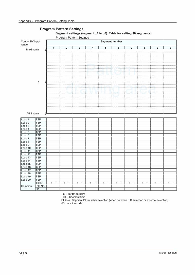
App-6 IM 04L51B01-31EN
Patterndrawing area
Program Pattern SettingsSegment settings (segment _1 to _0): Table for setting 10 segmentsProgram Pattern Settings
Control PV input range
Segment number
Maximum ( )_1 _2 _3 _4 _5 _6 _7 _8 _9 _0
( )
Minimum ( )
Loop 1 TSPLoop 2 TSPLoop 3 TSPLoop 4 TSPLoop 5 TSPLoop 6 TSPLoop 7 TSPLoop 8 TSPLoop 9 TSPLoop 10 TSPLoop 11 TSPLoop 12 TSPLoop 13 TSPLoop 14 TSPLoop 15 TSPLoop 16 TSPLoop 17 TSPLoop 18 TSPLoop 19 TSPLoop 20 TSP
CommonTIME : : : : : : : : : : : : : : : : : : : : PID No.JC
TSP: Target setpointTIME: Segment timePID No.: Segment PID number selection (when not zone PID selection or external selection)JC: Junction code
Appendix 2 Program Pattern Setting Table

App-7IM 04L51B01-31EN
Appendix
1
2
3
4
5
6
App
Index
PID number/Reference pointReference point, hysteresis, and reference deviation: Table for setting 20 loopsControl settingsWhen the PID selection is Zone PID selection, set the reference point, hysteresis, or reference deviation.
Setup item Loop (loop number)1 2 3 4 5 6 7 8 9 10
( L _ _ _ ) ( L _ _ _ ) ( L _ _ _ ) ( L _ _ _ ) ( L _ _ _ ) ( L _ _ _ ) ( L _ _ _ ) ( L _ _ _ ) ( L _ _ _ ) ( L _ _ _ )Point 1Point 2Point 3Point 4Point 5Point 6Point 7Zone PID switching hysteresisReference deviation
Setup item Loop (loop number)11 12 13 14 15 16 17 18 19 20
( L _ _ _ ) ( L _ _ _ ) ( L _ _ _ ) ( L _ _ _ ) ( L _ _ _ ) ( L _ _ _ ) ( L _ _ _ ) ( L _ _ _ ) ( L _ _ _ ) ( L _ _ _ )Point 1Point 2Point 3Point 4Point 5Point 6Point 7Zone PID switching hysteresisReference deviation
Appendix 2 Program Pattern Setting Table

App-8 IM 04L51B01-31EN
Time Event settingsTime event (1 to 16) settings (segment _1 to _0): Table for setting 10 segmentsProgram Pattern Settings
Segment_1 _2 _3 _4 _5 _6 _7 _8 _9 _0
Time event 1
Start ConditionOn time : : : : : : : : : : : : : : : : : : : :Off time : : : : : : : : : : : : : : : : : : : :
Time event 2
Start ConditionOn time : : : : : : : : : : : : : : : : : : : :Off time : : : : : : : : : : : : : : : : : : : :
Time event 3
Start ConditionOn time : : : : : : : : : : : : : : : : : : : :Off time : : : : : : : : : : : : : : : : : : : :
Time event 4
Start ConditionOn time : : : : : : : : : : : : : : : : : : : :Off time : : : : : : : : : : : : : : : : : : : :
Time event 5
Start ConditionOn time : : : : : : : : : : : : : : : : : : : :Off time : : : : : : : : : : : : : : : : : : : :
Time event 6
Start ConditionOn time : : : : : : : : : : : : : : : : : : : :Off time : : : : : : : : : : : : : : : : : : : :
Time event 7
Start ConditionOn time : : : : : : : : : : : : : : : : : : : :Off time : : : : : : : : : : : : : : : : : : : :
Time event 8
Start ConditionOn time : : : : : : : : : : : : : : : : : : : :Off time : : : : : : : : : : : : : : : : : : : :
Time event 9
Start ConditionOn time : : : : : : : : : : : : : : : : : : : :Off time : : : : : : : : : : : : : : : : : : : :
Time event 10
Start ConditionOn time : : : : : : : : : : : : : : : : : : : :Off time : : : : : : : : : : : : : : : : : : : :
Time event 11
Start ConditionOn time : : : : : : : : : : : : : : : : : : : :Off time : : : : : : : : : : : : : : : : : : : :
Time event 12
Start ConditionOn time : : : : : : : : : : : : : : : : : : : :Off time : : : : : : : : : : : : : : : : : : : :
Time event 13
Start ConditionOn time : : : : : : : : : : : : : : : : : : : :Off time : : : : : : : : : : : : : : : : : : : :
Time event 14
Start ConditionOn time : : : : : : : : : : : : : : : : : : : :Off time : : : : : : : : : : : : : : : : : : : :
Time event 15
Start ConditionOn time : : : : : : : : : : : : : : : : : : : :Off time : : : : : : : : : : : : : : : : : : : :
Time event 16
Start ConditionOn time : : : : : : : : : : : : : : : : : : : :Off time : : : : : : : : : : : : : : : : : : : :
Appendix 2 Program Pattern Setting Table

App-9IM 04L51B01-31EN
Appendix
1
2
3
4
5
6
App
Index
Time event (17 to 32) settings (segment _1 to _0): Table for setting 10 segmentsProgram Pattern Settings
Segment_1 _2 _3 _4 _5 _6 _7 _8 _9 _0
Time event 17
Start ConditionOn time : : : : : : : : : : : : : : : : : : : :Off time : : : : : : : : : : : : : : : : : : : :
Time event 18
Start ConditionOn time : : : : : : : : : : : : : : : : : : : :Off time : : : : : : : : : : : : : : : : : : : :
Time event 19
Start ConditionOn time : : : : : : : : : : : : : : : : : : : :Off time : : : : : : : : : : : : : : : : : : : :
Time event 20
Start ConditionOn time : : : : : : : : : : : : : : : : : : : :Off time : : : : : : : : : : : : : : : : : : : :
Time event 21
Start ConditionOn time : : : : : : : : : : : : : : : : : : : :Off time : : : : : : : : : : : : : : : : : : : :
Time event 22
Start ConditionOn time : : : : : : : : : : : : : : : : : : : :Off time : : : : : : : : : : : : : : : : : : : :
Time event 23
Start ConditionOn time : : : : : : : : : : : : : : : : : : : :Off time : : : : : : : : : : : : : : : : : : : :
Time event 24
Start ConditionOn time : : : : : : : : : : : : : : : : : : : :Off time : : : : : : : : : : : : : : : : : : : :
Time event 25
Start ConditionOn time : : : : : : : : : : : : : : : : : : : :Off time : : : : : : : : : : : : : : : : : : : :
Time event 26
Start ConditionOn time : : : : : : : : : : : : : : : : : : : :Off time : : : : : : : : : : : : : : : : : : : :
Time event 27
Start ConditionOn time : : : : : : : : : : : : : : : : : : : :Off time : : : : : : : : : : : : : : : : : : : :
Time event 28
Start ConditionOn time : : : : : : : : : : : : : : : : : : : :Off time : : : : : : : : : : : : : : : : : : : :
Time event 29
Start ConditionOn time : : : : : : : : : : : : : : : : : : : :Off time : : : : : : : : : : : : : : : : : : : :
Time event 30
Start ConditionOn time : : : : : : : : : : : : : : : : : : : :Off time : : : : : : : : : : : : : : : : : : : :
Time event 31
Start ConditionOn time : : : : : : : : : : : : : : : : : : : :Off time : : : : : : : : : : : : : : : : : : : :
Time event 32
Start ConditionOn time : : : : : : : : : : : : : : : : : : : :Off time : : : : : : : : : : : : : : : : : : : :
Appendix 2 Program Pattern Setting Table

App-10 IM 04L51B01-31EN
PV Event settingsPV event (1 to 16) settings (segment _1 to _0): Table for setting 10 segmentsProgram Pattern Settings
Segment_1 _2 _3 _4 _5 _6 _7 _8 _9 _0
PV event 1
Loop numberTypeSetpoint
PV event 2
Loop numberTypeSetpoint
PV event 3
Loop numberTypeSetpoint
PV event 4
Loop numberTypeSetpoint
PV event 5
Loop numberTypeSetpoint
PV event 6
Loop numberTypeSetpoint
PV event 7
Loop numberTypeSetpoint
PV event 8
Loop numberTypeSetpoint
PV event 9
Loop numberTypeSetpoint
PV event 10
Loop numberTypeSetpoint
PV event 11
Loop numberTypeSetpoint
PV event 12
Loop numberTypeSetpoint
PV event 13
Loop numberTypeSetpoint
PV event 14
Loop numberTypeSetpoint
PV event 15
Loop numberTypeSetpoint
PV event 16
Loop numberTypeSetpoint
Appendix 2 Program Pattern Setting Table

App-11IM 04L51B01-31EN
Appendix
1
2
3
4
5
6
App
Index
PV event (17 to 32) settings (segment _1 to _0): Table for setting 10 segmentsProgram Pattern Settings
Segment_1 _2 _3 _4 _5 _6 _7 _8 _9 _0
PV event 17
Loop numberTypeSetpoint
PV event 18
Loop numberTypeSetpoint
PV event 19
Loop numberTypeSetpoint
PV event 20
Loop numberTypeSetpoint
PV event 21
Loop numberTypeSetpoint
PV event 22
Loop numberTypeSetpoint
PV event 23
Loop numberTypeSetpoint
PV event 24
Loop numberTypeSetpoint
PV event 25
Loop numberTypeSetpoint
PV event 26
Loop numberTypeSetpoint
PV event 27
Loop numberTypeSetpoint
PV event 28
Loop numberTypeSetpoint
PV event 29
Loop numberTypeSetpoint
PV event 30
Loop numberTypeSetpoint
PV event 31
Loop numberTypeSetpoint
PV event 32
Loop numberTypeSetpoint
Repeat function settingsProgram Pattern Settings
Setup item SetpointRepeat functionNumber of repeat cyclesRepeat cycle start segment numberRepeat cycle end segment number
Appendix 2 Program Pattern Setting Table

App-12 IM 04L51B01-31EN
Appendix 3 Terminology
This section explains the terminology used in this manual.
Term Explanation15 V DC loop power supply A function that supplies15 V DC power to a 2-wire transmitter.Advance The act of moving from the current segment to the next segment during program
control.Alarm level The alarm status.Alarm level status The output status assigned to the alarm level.Alarm mode A mode in which alarm output action is set according to the operating status.Anti-reset windup Where there is a large deviation at the start of the control operation, for example,
integral outputs are accumulated and the PV exceeds the SP, thereby causing the output to overshoot. To avoid this, the controller provides an anti-reset windup function for suppressing an extreme integral output by stopping PID computations. Same applies to the case of undershoot. This function is running all the time.
Auto-tuning A function that automatically calculates the PID settings. It temporarily executes ON/OFF control, calculates appropriate PIDs from response data obtained, and sets them. This method is referred to as the limit cycle method.
Bias function A function that adds a bias to the PV input and uses the result in the display and control. This function is used to finely adjust the values when the values are within the accepted accuracy range but deviate from those of other devices.
Burnout A condition in which a break in the input signal is detected.Carbon potential (CP) A term indicating the carburizing potential of atmosphere for heating steel.Cascade control When cascade control is used in a feedback control system, the target setpoint
of the secondary PID is varied according to the output signal of the primary PID measuring the control target. This is used when the dead time between changes in the control output to PV input is large.Cascade control has two control computation units and provides a control function that executes cascade control from a single PID Control Module.
Cascade mode A mode in which cascade control is being used.Continuous PID control A function that outputs the PID computation result using a current (analog signal)
proportional to the PID computation value.Control mode Control modes define the controls that a single PID Control Module can execute.
Single loop control, cascade control, and loop control with PV switching are available.
Control output The act of outputting the control computation result with a current or voltage pulse.
Control period The cycle time from when a PV is received and control computation is performed to when output is delivered based on the results. This is a common setting for the system and can be set to 100 ms or 200 ms. The sampling interval (scan interval) of the analog input terminals is synchronized to the control period.
Control type PID control or ON/OFF control.Correction Factor A function used to set a compensation value on the device side and a
compensation value on the sensor side and manage them. Recorder option /AH is required.
Cycle time Cycle time is the basic cycle period for the voltage pulse output to repeat on and off during time proportional PID control.
Delay timer There are two delay timers: on-delay timer and off-delay timer. On-delay timer starts a timer when an alarm condition occurs and turns on the alarm when the timer expires. Off-delay timer starts a timer when the alarm condition clears (returns to normal condition) and turns off the alarm when the timer expires.
Derivative action An action that changes the output in proportion to the deviation derivative value (rate-of-change). The derivative time is defined as the time required with PD action to develop, when a constant-slope change in deviation is imposed, an output change due to derivative action that is exactly equal to the change due to proportional action.
Deviation Deviation = SP – PV

App-13IM 04L51B01-31EN
Appendix
1
2
3
4
5
6
App
Index
Deviation derivative type PID Because derivative actions work on the changes in the control deviation (difference between the PV and SP, quick response is exhibited to changes in the target setpoint. This method is useful when SP trackability is important.
Direct action When the SP is less the PV, the system operates to increase the OUT value (control output). The reverse of this action is reverse action.
External input In place of the analog input of the PID control module itself, an external input channel (input, math, communication) is used for the PV input.
Filter function A filter is applied if the PV input reading fluctuates greatly and the lower digits are difficult to read. The filter provides a first-order lag calculation.
Final target setpoint During program control, this is the target setpoint of each segment.Fixed-point control A control in which the target setpoint (SP) is constant.Fixed-point control mode A mode that is used when you do not want to disturb the PV as a result of the
control output (OUT) reacting too sensitively when the target setpoint (SP) is changed during continuous fixed-point control. In local mode, the output value (OUT) does not change drastically when the target setpoint (SP) is changed. The deviation is gradually removed using only the integral term (I) in response to the deviation that occurs. This is useful for fast-responding processes such as flow-rate control and pressure control.
Hold The act of holding the progress of a pattern during program control.Hysteresis There are two types of hysteresis: control hysteresis and alarm hysteresis.
Control hysteresis defines the value for turning the output on and off according to the SP during ON/OFF control. Alarm hysteresis defines the alarm’s dead band. Increasing the band reduces chattering.
Input error preset output A function that selects between 0% control output, 100% control output, or preset output when an input error occurs.
Integral action The integral action (I action) is a function that will automatically diminish the offset (steady-state deviation) that is inherently unavoidable with proportional action alone.
Linearizer approximation Linearizer approximation is used when the input signal and the required measurement signal have a non-linear relationship, for example, when trying to obtain the volume from a sphere tank level. Output values for 12 input values can be assigned.
Linearizer bias Linearizer bias is used to correct an input signal affected by sensor deterioration. Compensation values are set to results obtained by adding a bias to each of the 12 input values.
Local mode The local mode function stops program operation and performs fixed-point control.Loop control Loop control has a temperature indicator section and a target setpoint section.
Control signals are generated based on the difference between the indication (temperature measurement) and setpoint and works to bring the temperature to the setpoint.
Loop control with PV switching A function that switches between two PV inputs according to measurement ranges or the like and uses the result as the PV.
Loop number A number, which starts with the letter L, assigned to a loop. It is defined by the unit number, slot number, and loop number. Example: GX20 main unit slot 1 loop 2 Loop number: L012
Measurement input range A range of measurable input values.ON/OFF control ON/OFF control compares the SP and PV and outputs an on or off signal
according to the positive or negative deviation (PV – SP).Output limiter A function that limits the control output to the operation range between high and
low limits.Output velocity limiter Output velocity limiter prevents the control output signal from changing suddenly
in order to protect the control valves (or other actuators) and controlled process.Over-integration suppressing function
See “anti-reset windup.”
Overshoot suppressing function “Super”
A function that controls the PV from overshooting or undershooting the target setpoint.
PID channel PID channels are used to display control data and I/O data of PID control modules on trend or digital displays and save the data as recorded data. There are 26 PID channels for each module.
PID control A control in which the PV is converged to the SP by combining proportional control, integral control, and derivative control.
Appendix 3 Terminology

App-14 IM 04L51B01-31EN
PID control mode There are two PID control modes: standard PID control mode and fixed-point control mode. See “standard PID control mode” and “fixed-point control mode.” The optimal control algorithm is automatically selected according to the operation mode status to control the system.
Preset output A function that outputs a constant value (preset output value) , separate from the control output value up to that point, when the operation mode is changed to STOP or RESET.
Program control A function that can be used to change the SP over time according to a preset program pattern.
Program operation The program operation can be used to change the SP over time according to a preset program pattern. A program pattern consists of several segments.
Program pattern A program pattern consists of several segments. You can create a program pattern by setting the final target setpoint of each segment, segment time, PV events, time events, and so on.
Proportional action The proportional band (P) is defined as the amount of change in input (or deviation), as a percentage of span, required to cause the control output to change from 0% to 100%.
PV derivative type PID Control method in which stable control output is possible because derivative actions work only on the PV. Even when the SP is changed significantly, the control output does not change drastically, and the deviation is gradually eliminated.
PV event The PV event function outputs preset PV alarms, deviation alarms, and the like according to the program progression.
PV input Input such as temperature, flow rate, and pressure from the control target.PV tracking PV tracking function is used to prevent abrupt PV changes. This function forces
the SP to match the PV temporarily. Then, the SP is returned automatically to its original SP at the SP ramp rate.
Ramp-prioritized PV start During program control, control starts by prioritizing the ramp-rate of the first segment.
Ratio bias Ratio bias computing performs ratio computation and bias addition for remote input.
Reference deviation A function for switching the PID group according to the deviation.Reference Junction Compensation (RJC)
The temperature of a measurement target can be determined by measuring the temperature of the terminal section (reference contact) of the measuring instrument that a thermocouple is connected to and compensating the calculation based on the measurement results. This act is referred to as reference junction compensation (RJC).
Reference point The point for switching the PID when zone PID is in use. Up to eight points can be set.
Remote input An external input used as remote setpoints.Remote mode A mode in which external input is used for the target setpoint.Repeat function The repeat function repeatedly runs a given segment (consecutive multiple
segments also possible) in a program pattern.Reset mode A state in which program operation is stopped.Resistance-temperature detector (RTD)
An RTD is a temperature sensor that makes use of a property of metal that exhibits increasing electric resistance with increases in temperature.
Restart mode A function for selecting how to control the system after a power recovery. Available options are continue the operation before the power failed, auto, manual, and reset.
Retransmission output Retransmission output transmits PV, SP, control output (OUT), and the like using analog signals to recorders and the like.
Reverse action When the SP is greater than the PV, the system operates to increase the OUT value (control output). The reverse of this action is direct action.
Segment An element that comprise a program pattern. Up to 99 segments can be created in a pattern.
Single loop control A basic control function with two control computation units.Soak state A state in which the SP in a program pattern is constant.SP limiter function A function that limits the SP setting range (high and low limits).SP ramp-rate setting function SP ramp-rate setting function forces SP to change at a fixed rate when SP is
changed in order to prevent abrupt changes in SP.
Appendix 3 Terminology

App-15IM 04L51B01-31EN
Appendix
1
2
3
4
5
6
App
Index
Split computation output Split computation output is useful for the case where multiple operating units (up to two) for switching, for example, hot and cool water are linked for control. There are two characteristics of split computations: V-mode characteristics and Parallel-mode characteristics.
Standard PID control mode A mode in which PV derivative type PID is employed to quickly reach the new target setpoint when the target setpoint is changed. In PV derivative type PID, output P, which is proportional to the deviation caused by a target setpoint (SP) change, is immediately output in order to quickly reach the new target setpoint. This is useful for controlling temperature and other slow-responding parameters.
Standby action Standby action disables alarms until the first time the alarm condition ceases. When a value enters an area in which alarms do not occur, the stand-by action is reset.
Starting target setpoint During program control, control starts from the specified starting target setpoint regardless of the starting PV input.
Super function The Super function monitors the deviation for evidence that there is a danger of overshoot, and on sensing such danger automatically changes the setpoint temporarily to a somewhat lower value (sub-SP). Once the danger of overshoot appears diminished, the function returns the effective SP gradually to the true SP. “Fuzzy ratiocination” techniques are employed in the algorithms used to change the SP to the lower temporary value, and to return it gradually to the true SP.
Target setpoint The target setpoint of the control target. There are two types of target setpoints used in control computation: local target setpoint, which is set to the specified value, and remote target setpoint, which is varied continuously according to inputs received through the I/O channels or math channels.
Target setpoint (SP) tracking The setpoint at the start of program control.Target setpoint number SP group refers to a collection of SPs, PID groups, and alarm values. There are
multiple SP groups numbered from 1 to 8. Target setpoint number refers to this number.
Thermocouple A thermocouple is a temperature sensor made of two different types of metals that forms a closed circuit causing a current to flow when a temperature difference is detected.
Tight shut function Tight shut function fully closes the control valve (or other actuators) beyond its positioner dead band.
Time event The time event function starts a timer at the start of the segment and turns on the contact output when the specified time expires.
Time proportional PID control In time proportional PID control, the control output value of the PID computation result is converted into a ratio of the cycle on/off time. At 100% output, the output is always on. At 0% output, the output is always off. At 25% output, the output is on 25% of the cycle time and off 75% of the cycle time.
Time-prioritized PV start During program control, control starts from the starting PV regardless of the starting SP.
Universal input A function that allows the PV type to be set to thermocouple, RTD, or DC voltage/current through configuration.
Universal output A function that allows current/voltage pulse control output to be selected through configuration.
Wait Function The wait function pauses the progression of a program when the PV cannot follow the SP.
Wait function (segment switch wait)
During program control, this wait function forces the program to wait when the PV has not reached the target setpoint (TSP) before advancing to the next segment. If the PV reaches the wait zone before the wait time expires, the program advancing to the next segment at that point. If not, the program advancing to the next segment when the wait time expires.
Wait function (Wait within segment interval)
During program control, this wait function forces the program to wait when the PV tracking is slow and the deviation from the SP becomes large.
Zone PID A function for switching between PID parameter groups according to the PV or SP. This function is useful for reactors in which the chemical reaction gain changes depending on the temperature.
Appendix 3 Terminology

Blank