model h.e. steam boilers - lattnerlattner.com/userfiles/literature/lattner boiler company... ·...
TRANSCRIPT

Lattner Boiler Company
Model H.E. Steam Boilers
INSTRUCTION MANUAL
January 2006
Lattner Boiler Company 1411 9th St. SW
Cedar Rapids, IA 52404 T: (800) 345-1527 F: (319) 366-0770
E: [email protected] www.lattnerboiler.com

2
Index
General Description Page 4 A. Boiler Design B. Boiler Connections C. Boiler Trim D. Fuel Burning System E. Fuel Train F. Control Panel G. Combustion Safeguard H. Factory Tests I. Nameplates & Stamping J. Guarantees
………………………………………………………………………….4 ………………………………………………………………………….4 ………………………………………………………………………….4 ………………………………………………………………………….5 ………………………………………………………………………….5 ………………………………………………………………………….5 ………………………………………………………………………….6 ………………………………………………………………………….6 ………………………………………………………………………….6 ………………………………………………………………………….6
Section I: Installation Page 7 A. Unloading B. Rigging C. Placement of Boiler D. Combustion Air E. Stack F. Boiler Shipped with Controls
Removed G. Steam Outlet H. Blowdown Piping I. Safety Valve J. Gas Train Piping K. Boiler Feed Systems L. Electrical Connections M. Before Firing the Boiler N. Pressuretrols: Controller & Limit O. Start Up of Standard Burners
………………………………………………………………………….7 ………………………………………………………………………….7 ………………………………………………………………………….7 ………………………………………………………………………….7 ………………………………………………………………………….8 ………………………………………………………………………….8 ………………………………………………………………………….8 ………………………………………………………………………….8 ………………………………………………………………………….9 ………………………………………………………………………….9 ………………………………………………………………………...10………………………………………………………………………...11………………………………………………………………………...11………………………………………………………………………...11………………………………………………………………………...12
Section II: Boiler Care Page 14 A. General B. New Boiler Cleanout C. Water Conditions D. Water Treatments & Chemicals E. Water Softener F. Foaming, Bouncing, & Carryover G. Water Treatment Summary H. Blowdown I. Feedwater System J. Burner Adjustment K. Sight Glass L. External Inspections M. Internal Inspections
………………………………………………………………………...14………………………………………………………………………...14………………………………………………………………………...14………………………………………………………………………...14………………………………………………………………………...14………………………………………………………………………...15………………………………………………………………………...15………………………………………………………………………...15………………………………………………………………………...15………………………………………………………………………...16………………………………………………………………………...16………………………………………………………………………...16………………………………………………………………………...17
Section III: Maintenance Page 18 A. Daily Blowdown B. Weekly Maintenance C. General Maintenance D. Table 1: Recommended Testing
Schedule E. Hand Hole Removal & Re-Installation F. Sight Glass Removal & Re-Installation
………………………………………………………………………...18………………………………………………………………………...18………………………………………………………………………...18………………………………………………………………………...19 ………………………………………………………………………...20………………………………………………………………………...21
3
G. McDonnell Miller Servicing H. Warrick Relay Replacement I. Auxiliary Low Water Cut-Off Probe
Cleaning
………………………………………………………………………...22………………………………………………………………………...23………………………………………………………………………...23
Section IV: Troubleshooting Page 24 A. Normal Operation B. Basic Service Tools C. Before You Begin D. Troubleshooting
………………………………………………………………………...24………………………………………………………………………...24………………………………………………………………………...24………………………………………………………………………...25
Lattner Boiler Limited Warranty Page 26
Standard Terms & Conditions Page 27 Additional Support Literature Page 28

4
General Description
WARNING: All installation procedures must be followed completely by a competent installer familiar with boilersand boiler accessories. CAUTION: Read and follow all instructions before installing any boiler equipment. All cover plates, enclosures and guards must be maintained and in place at all times, except during maintenance and servicing.
A. Boiler Design
The Model HE is a single pass carbon steel vertical boiler of the tubeless design that includes an integral furnace and extended heat transfer surfaces. In accordance with the latest edition of the ASME Code, the boiler is constructed for either low pressure steam or high pressure steam, up to 150 psi.
1. Gas Flow The heat transfer design of the Model HE boiler provides single pass, turbulent flow to ensure maximum heated gas travel and heat transfer. Heat loop design provides even flow of heat over entire pressure vessel, ensuring high efficiency. 2. Water Circulation Feedwater make-up enters the side of the vessel below the steaming surface. Directing the make-up into a non-steaming portion of the boiler eliminates the possibility of collapsing steam bubbles and increases water circulation inside the pressure vessel. 3. Tubeless Boiler tubes are eliminated with the use of solid carbon steel loops. These loops are spot welded to the pressure vessel to enhance heat absorption into the boiler water. Fouling, plugging, and replacement of tubes is eliminated with the use of loops. 4. Furnace The combustion chamber or furnace is centrally located beneath the pressure vessel. 10, 15, and 20 horsepower models include an integral refractory lined furnace. 5. Inner Casing & Insulation A stainless steel gas barrier encases the pressure vessel and combustion chamber, ensuring even gas travel and heat transfer. This barrier is backed with 2” of mineral wool insulation. 6. Outer Casing
The outer casing is fabricated of a single 16 gauge steel jacket. The jacket is painted with high temperature enamel to ensure corrosion resistance and longevity.
7. Waterside Inspection A minimum of one hand hole inspection plate is provided in the pressure vessel (located on the top of the boiler for waterside inspection). The 10, 15, and 20 horsepower models include hand holes on the lower left side of the boiler. 8. Boiler Lifting Lug One lug is provided to facilitate lifting and rigging the boiler into place. The lug is located on the top centerline of the pressure vessel.
B. Boiler Connections
The following connections are factory installed in accordance with ASME code:
1. Steam Connection
The system supply connection is located on the top, side of the boiler and is threaded as standard. In some instances or for specific project requirements, the nozzle connection may be flanged. 2. Boiler Blowdown Valve/Drain A boiler blowdown valve is provided on either the back or left side of the pressure vessel for periodic bottom blowdown. 3. Feedwater Make-Up A threaded connection is provided on the side(s) centerline of the boiler for connection to the make-up solenoid or condensate return system. 4. Exhaust Gas Vent The connection for the stack or breaching is located at the top of the boiler. This is a sleeve connection, with the opening in accordance with the nominal dimension and rating sheets.
C. Boiler Trim The following are factory installed standard trim and control items. Trim items are provided in accordance with the ASME Code and the controls and are UL listed.
5
1. Relief Valve In compliance with the ASME Code, a steam boiler pressure relief valve is provided. Size and quantity are determined by the valve setting, valve capacity, and the ASME Code. Valve may be shipped loose to prevent possible damage during shipment. 2. Water Column Factory mounted and piped complete with gauge glass, gauge glass drain valve, gauge glass isolation valves, column drain valve, and a minimum of 1” equalized piping and crosses for inspection and clean-out. 3. Low Water Cut-Off To prevent burner operation whenever a low water condition occurs, an electronic probe-sensing device, or float operated control is furnished in the water column. This device is wired in series to the burner combustion safeguard control to prevent burner operation whenever a low water condition occurs. 4. Pump Control When a probe sensing main level control is furnished, two stainless steel probes are furnished in the water column to provide pump ON/OFF operation for water make-up. These probes are wired to an electronic interlock relay for pump or water valve control. However, if the column is a float-actuated device, a snap acting single pole single throw switch activates a pump contactor for ON/OFF pump or solenoid valve operation. 5. Auxiliary Low Water Cut-Off An additional control, separate from the primary low water control is provided to prevent burner operation if a low-low water condition exists. This device is an internal probe control located on the side of the pressure vessel, and requires manual reset whenever a low water condition occurs.
6. Steam Pressure Gauge A 3-1/2" dial pressure gauge is furnished as standard. The range of the gauge will be in accordance with the safety valve setting, based on 1.5 times the valve setting for high-pressure units, and two times the design pressure of low-pressure units. 7. Steam Pressure Controls At least two controls are furnished with each boiler: One for ON/OFF operation (controller) and one for preventing burner operation if excess steam pressure is sensed (limit). The limit control is a manual reset control. 8. Valves Standard valve piping package consists of one (1) feedwater stop valve, one (1) quick open bottom blowdown valve, and one (1) slow open blowdown valve.
D. Fuel Burning System The boiler is furnished with a UL approved atmospheric draft burner system. This system is mounted and wired integral with the front centerline of the boiler.
1. Burner Type The atmospheric draft burner is designed for Natural or LP gas only. 2. Burner Operation The burner is designed to operate in an ON/OFF mode. 3. Ignition/Pilot Gas fired units are equipped with either a thermocouple pilot (standing) or spark ignited (intermittent) pilot assembly. 4. Atmospheric Burners
HE boilers include sheet metal atmospheric burners. 5. Fuel/Air Control The control of combustion air is managed by adjusting the air shutter on each sheet metal burner and gas valve supplied with the gas train (gas inlet pressure and volume).
E. Fuel Train The burner is equipped with factory mounted fuel safety control and safety shutoff valves. Each fuel piping assembly is equipped with the following:
1. Gas Assembly Gas train is a piped and wired assembly, consisting of main gas pressure regulator, safety shutoff valve(s), manual shutoff cock(s), in accordance with the latest UL and CSD-1 requirements. Main gas valve may also function as the main gas pressure regulator.
F. Control Panel A NEMA 1A enclosed (powder coated finish) control panel is mounted integral to the burner or on an independent bracket mounted on the boiler. This panel contains following components:
1. Boiler ON/OFF Switch Provided to interrupt control power to the 120 volt control circuit. Does not disconnect the main power source. 2. Pump ON/OFF Switch Provided to isolate the pump control circuit.

6
3. Terminals
Provided for the connection of the 120 volt supply and for external connections for field wiring. 4. Relays Provided for water level and pump controls. 5. Wiring/Controls All devices and wiring are in accordance with the latest UL/NFPA 70 requirements. Each device is UL listed or recognized and bears the UL label or stamp. As standard, flexible conduit is used. Or, in accordance with specifications, thin wall or seal tight may be used to connect controls to main panel box.
G. Combustion Safeguard
1. Thermocouple Pilots Thermocouple pilots and controls are standard on models below 400,000 BTUs. 2. Solid State Control Spark-ignited pilot (intermittent) models may be provided on all models with electronic combustion safeguard controls. These pre-programmed solid state controls are mounted adjacent to the burner, provide safe start sequencing of the burner during start-up, run, normal shutdown, and safety shutdown.
H. Factory Tests
1. Pressure Vessel The boiler is subjected to an ASME certified hydrostatic pressure test to ensure the pressure vessel meets the standards of the ASME Code. In accordance with the ASME Code, this test is supervised by an independent inspection agency. Upon acceptance of the test by the authorized independent inspector, the unit is stamped with the "M" symbol for 100 psi design units or with the "S" symbol for 125 psi and greater designs. One copy of the ASME data sheet is provided to the purchaser. One copy is sent to the National Board of Pressure Vessel Inspectors. The original copy is archived at Lattner.
2. Boiler Piping Hydro Each Section I High Pressure Boiler ("S" stamped), is subjected to an additional hydrostatic pressure test. This test includes the integral steam and water trim piping and the trim valves. An ASME P-6 piping hydro certificate can be provided for an additional cost. 3. Burner/Pressure Controls
All burner and boiler controls are checked for circuit continuity after wiring is complete. Factory fire testing may be requested as on option on some sizes.
I. Nameplates & Stamping
1. National Board of Pressure Vessel Inspectors The National Board of Pressure Vessel Inspectors registration number is stamped on the pressure vessel along with the boiler serial number, year built, maximum boiler output and minimum safety valve capacity. This information is stamped on the top head of the pressure vessel. A facsimile nameplate of this data stamping is mounted near or on the front door of the boiler control panel.
J. Guarantees
1. Efficiency The boiler package is guaranteed to operate at a minimum of 75% or greater, fuel input to steam pounds per hour output efficiency. 2. Warranty The complete package is warranted for a period of one (1) year from the date of initial start-up or 18 months from the date of shipment or notice to ship, whichever occurs first. 3. Damage This guarantee does not include items that are damaged due to circumstances of carelessness, neglect, or operating the unit beyond its capacity and rating.
7
Section I: Installation
WARNING: All installation procedures must be followed completely by a competent installer familiar with boilersand boiler accessories. CAUTION: Read and follow all instructions before installing any boiler equipment. All cover plates, enclosuresand guards must be maintained and in place at all times, except during maintenance and servicing.
A. Unloading The boiler was loaded by Lattner (including any accessories) and accepted by the transport company as undamaged. Therefore, before unloading the equipment, determine whether any shipping damage is apparent. Once the equipment is lifted from the trailer, any damage sustained during transit and not filed with the transport company will be the responsibility of the rigger or purchaser.
1. Lifting The boiler will arrive secured to a wooden skid/pallet and will include a lifting lug (top of the boiler). When moving or lifting the unit, DO NOT attach slings around the boiler or to the burner in an attempt to pull the boiler. 2. Forklift If lifting with a forklift, extended forks should be used and placed beneath the skid. Care must be taken to ensure that the boiler sits correctly on the forks such that the unit does not topple. Always note the weight of the boiler relative to the lifting capacity of the forklift. 3. Crane or Boom When lifting with a crane or boom, attach the hook to the lifting lug on top of the boiler. DO NOT attach slings or chains to any part of the boiler, boiler piping, or burner.
B. Rigging Always use a competent rigger that has experience moving and setting boilers. If the unit will be moved into the permanent location with a forklift, crane, or boom follow the directions in section A. However, if moving the unit through a tight space or into an area that will not permit a forklift, etc., place the boiler on rollers or on 2” pipes and roll the boiler into place. If the unit is dragged, attach chains to the base frame only. CAUTION: DO NOT lay the boiler on its side as the jacketing will not support the weight of the boiler without sustaining damage. If the entry is too narrow for the boiler and controls to pass through, removal of the trim and controls can be executed. One should properly denote all wiring and piping connections and match mark accordingly for attachment after the boiler is placed. It may be helpful to use a digital camera to record the location of trim items for reference.
C. Placement of Boiler
1. Floor Boiler must be placed on a level, noncombustible surface. NEVER install boiler on a wood floor or any other combustible surface (i.e., carpet, linoleum).
2. Combustible Surface Underwriter’s Laboratories specifies the following minimum clearances to combustible surfaces:
Top – 48” Sides – 36” Flue Pipe – 36”
3. Non-Combustible Surface When placing boiler near non-combustible surfaces (i.e., cement or cinder block walls), maintain 18” around the boiler for servicing. NOTE: Any state or local fire and building codes requiring additional clearances take precedence over the above requirements.
D. Combustion Air
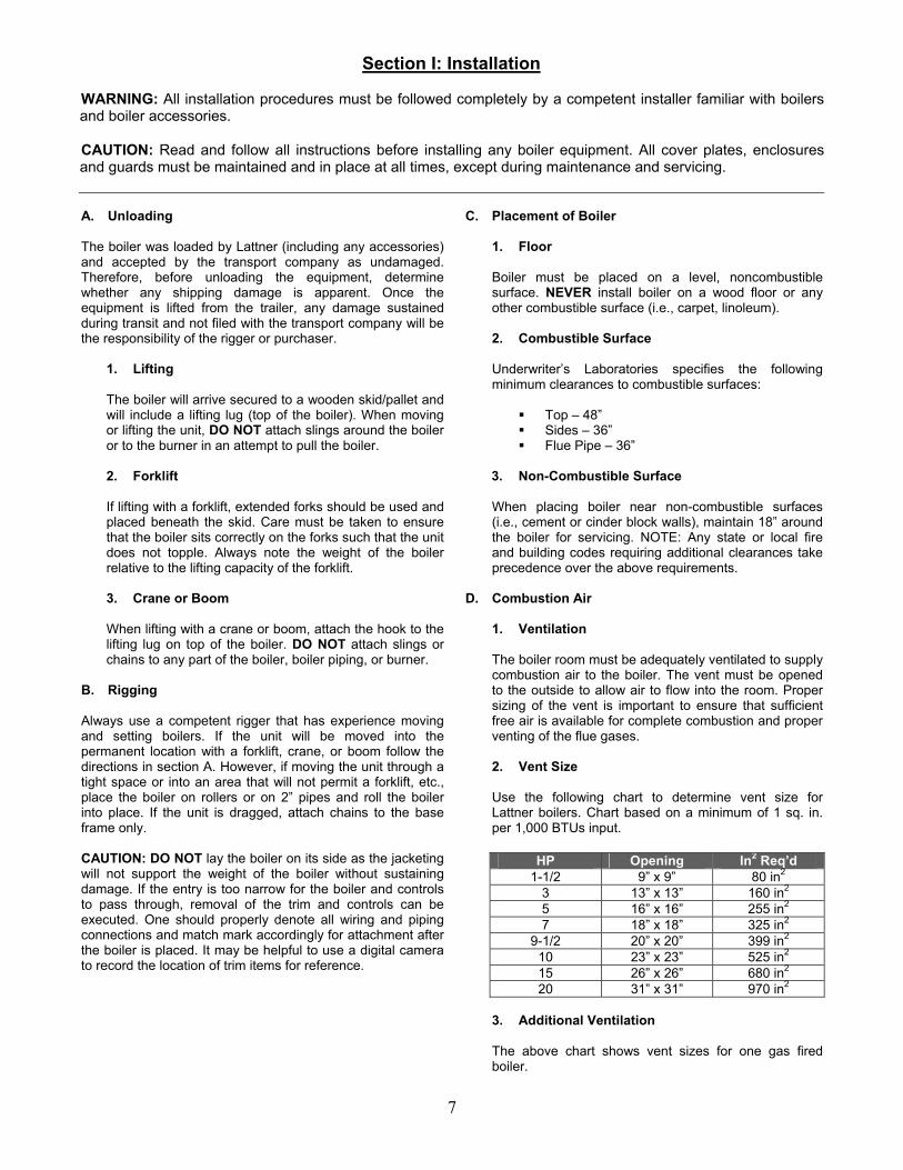
1. Ventilation The boiler room must be adequately ventilated to supply combustion air to the boiler. The vent must be opened to the outside to allow air to flow into the room. Proper sizing of the vent is important to ensure that sufficient free air is available for complete combustion and proper venting of the flue gases. 2. Vent Size Use the following chart to determine vent size for Lattner boilers. Chart based on a minimum of 1 sq. in. per 1,000 BTUs input.
HP Opening In2 Req’d 1-1/2 9” x 9” 80 in2
3 13” x 13” 160 in2 5 16” x 16” 255 in2 7 18” x 18” 325 in2
9-1/2 20” x 20” 399 in2 10 23” x 23” 525 in2 15 26” x 26” 680 in2 20 31” x 31” 970 in2
3. Additional Ventilation
The above chart shows vent sizes for one gas fired boiler.
8
If there is other equipment in the room that uses air (large water heaters, air compressors, other boilers, exhaust fans, etc.), additional venting capacity is required.
E. Stack
1. Specifications Install all stacks in compliance with state and local codes. Lattner recommends Category I Type B double wall non-positive stack for natural draft gas appliances. 2. Stack Size The entire stack must be the same size as the stack outlet on the boiler or larger. If the boiler stack is connected to other equipment, the stack size must be increased. NOTE: Any equipment with a forced draft burner must be vented separately from equipment with atmospheric burners. NEVER tie these stacks together. 3. Connections Limit connections to two 45 degree elbows. 4. Overall Length Avoid long runs of stack. A general rule is not to exceed 15 feet for every inch of stack diameter. For example, if the stack is 6” in diameter then the overall stack should not exceed 90 feet in length and height combined. 5. Horizontal Stack Avoid any horizontal runs of stack. If unavoidable, horizontal runs should have a minimum incline of 3” per foot. If a long horizontal run (4 feet or more) cannot be avoided, a draft inducer may be required to properly vent combustion gases. 6. Draft Regulation A vertical draft hood is supplied with every unit as standard equipment. 7. Walls & Ceilings When passing through combustible walls or ceilings, a stack thimble is required. The thimble must be double wall stack, 6” larger in diameter than the vent stack. The material used to close the opening between the stack and the stack thimble must be non-combustible.
F. Boiler Shipped with Controls Removed
1. Reassemble See assembly print inside boiler panel box. 2. Wiring Re-wiring the controls will be covered in L: Electrical Connections. DO NOT connect the power at this time.
G. Steam Outlet
1. Pipe Size Size steam pipe according to system requirements. 2. Outlet Size Refer to product literature sheet for steam outlet size on a particular boiler model. 3. Steam Stop Valve Install a steam stop valve in the steam line as close to the boiler as is practical. This allows boiler to be isolated from the system during service work and may be helpful in throttling steam flow. Required by ASME Code if the boiler is operated over 15 psi. Valve shall be rising stem or gate type valve. 4. Steam Piping Steam line should be pitched downward away from the boiler and toward a steam trap. If using a steam solenoid valve, the steam line should slope upward slightly to the solenoid valve, and after the solenoid valve, the steam line should slope downward. 5. Code Standards Piping must comply with all industry standards (ex. ANSI B31.1) and all state and local codes.
H. Blowdown Piping
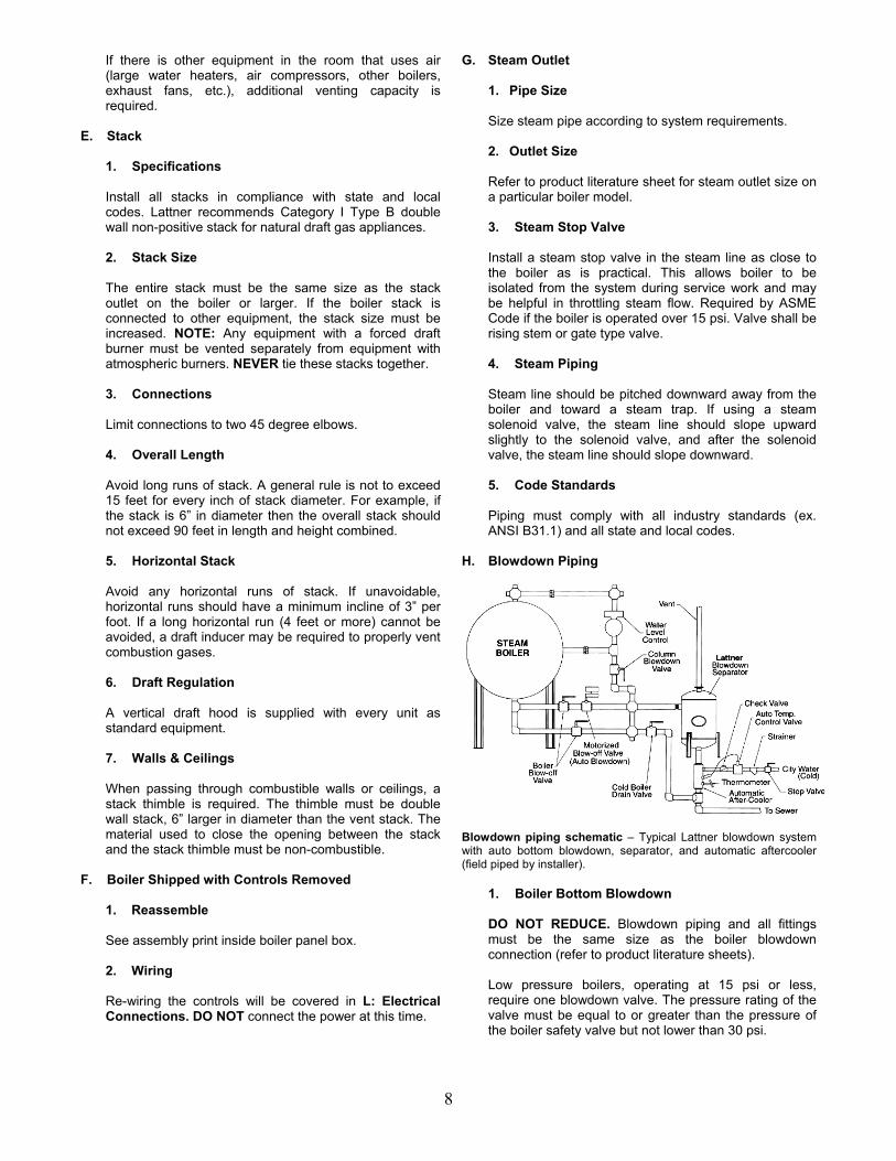
Blowdown piping schematic – Typical Lattner blowdown system with auto bottom blowdown, separator, and automatic aftercooler (field piped by installer).
1. Boiler Bottom Blowdown DO NOT REDUCE. Blowdown piping and all fittings must be the same size as the boiler blowdown connection (refer to product literature sheets). Low pressure boilers, operating at 15 psi or less, require one blowdown valve. The pressure rating of the valve must be equal to or greater than the pressure of the boiler safety valve but not lower than 30 psi.
9
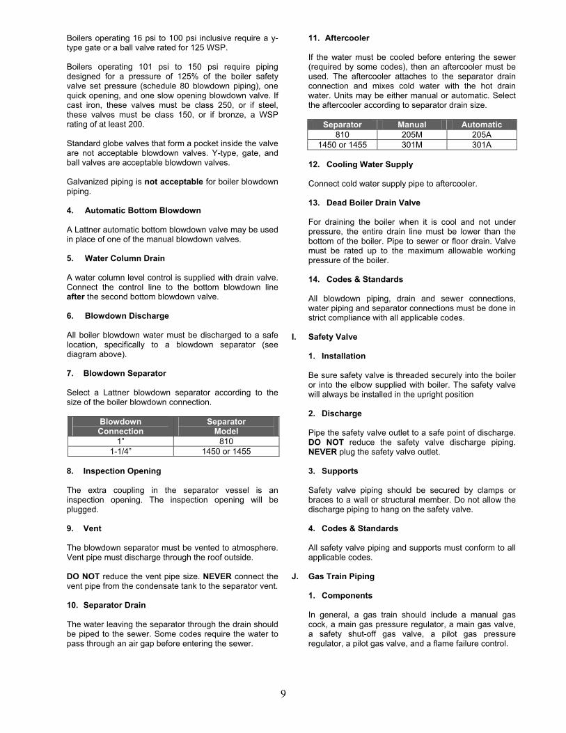
Boilers operating 16 psi to 100 psi inclusive require a y-type gate or a ball valve rated for 125 WSP. Boilers operating 101 psi to 150 psi require piping designed for a pressure of 125% of the boiler safety valve set pressure (schedule 80 blowdown piping), one quick opening, and one slow opening blowdown valve. If cast iron, these valves must be class 250, or if steel, these valves must be class 150, or if bronze, a WSP rating of at least 200. Standard globe valves that form a pocket inside the valve are not acceptable blowdown valves. Y-type, gate, and ball valves are acceptable blowdown valves. Galvanized piping is not acceptable for boiler blowdown piping. 4. Automatic Bottom Blowdown A Lattner automatic bottom blowdown valve may be used in place of one of the manual blowdown valves. 5. Water Column Drain A water column level control is supplied with drain valve. Connect the control line to the bottom blowdown line after the second bottom blowdown valve. 6. Blowdown Discharge All boiler blowdown water must be discharged to a safe location, specifically to a blowdown separator (see diagram above). 7. Blowdown Separator Select a Lattner blowdown separator according to the size of the boiler blowdown connection.
Blowdown Connection
Separator Model
1” 810 1-1/4” 1450 or 1455
8. Inspection Opening The extra coupling in the separator vessel is an inspection opening. The inspection opening will be plugged. 9. Vent The blowdown separator must be vented to atmosphere. Vent pipe must discharge through the roof outside. DO NOT reduce the vent pipe size. NEVER connect the vent pipe from the condensate tank to the separator vent. 10. Separator Drain The water leaving the separator through the drain should be piped to the sewer. Some codes require the water to pass through an air gap before entering the sewer.
11. Aftercooler If the water must be cooled before entering the sewer (required by some codes), then an aftercooler must be used. The aftercooler attaches to the separator drain connection and mixes cold water with the hot drain water. Units may be either manual or automatic. Select the aftercooler according to separator drain size.
Separator Manual Automatic
810 205M 205A 1450 or 1455 301M 301A
12. Cooling Water Supply Connect cold water supply pipe to aftercooler. 13. Dead Boiler Drain Valve For draining the boiler when it is cool and not under pressure, the entire drain line must be lower than the bottom of the boiler. Pipe to sewer or floor drain. Valve must be rated up to the maximum allowable working pressure of the boiler. 14. Codes & Standards All blowdown piping, drain and sewer connections, water piping and separator connections must be done in strict compliance with all applicable codes.
I. Safety Valve
1. Installation Be sure safety valve is threaded securely into the boiler or into the elbow supplied with boiler. The safety valve will always be installed in the upright position 2. Discharge Pipe the safety valve outlet to a safe point of discharge. DO NOT reduce the safety valve discharge piping. NEVER plug the safety valve outlet. 3. Supports Safety valve piping should be secured by clamps or braces to a wall or structural member. Do not allow the discharge piping to hang on the safety valve. 4. Codes & Standards All safety valve piping and supports must conform to all applicable codes.
J. Gas Train Piping
1. Components In general, a gas train should include a manual gas cock, a main gas pressure regulator, a main gas valve, a safety shut-off gas valve, a pilot gas pressure regulator, a pilot gas valve, and a flame failure control.
10
2. Combination Gas Valve Some Lattner gas trains include combination gas valves. Combination gas valves simultaneously function as gas pressure regulators, flame failure controls, pilot gas valves, and main gas valves. Combination gas valves may be supplied with either thermocouple (standing) pilots or spark-ignited (intermittent) pilots. Combination gas valves are only available on boilers 10 hp and smaller. 3. Diaphragm Gas Valve Some Lattner gas trains include diaphragm gas valves. Diaphragm gas valves simultaneously function as gas pressure regulators and main gas valves. Separate pilot gas valves must be used with a diaphragm gas valve. Diaphragm gas valves may be supplied with either thermocouple (standing) pilots or spark-ignited (intermittent) pilots.
4. Motorized Gas Valve With the motorized gas valve, the main gas valve and pressure regulator are two separate components. The motorized gas valve is a two piece valve. The lower section is the valve body, which is a plunger valve. The upper section is the actuator. The actuator has a small built-in hydraulic system. The hydraulic system opens and closes the valve. The motorized gas valve is a gas valve only, and has no other functions. This gas train requires a separate main gas pressure regulator, pilot gas pressure regulator and pilot valve.
a. Spark-Ignited Pilot
The boiler will be supplied with a flame safeguard control and an ignition transformer. With these controls, the boiler will have a spark-ignited pilot. This system will shut off the main and pilot gas within four seconds of a pilot failure.
b. Thermocouple Pilot The boiler will have a pilot switch and a thermocouple for igniting the main burners.
NOTE: For additional information on the gas train refer to the assembly prints and product literature sheets. 5. Gas Supply Pipe The gas pipe to the boiler must be at least the same size as the gas train supplied with the boiler. DO NOT reduce. 6. Drip Leg Gas supply piping must be installed with a proper drip leg ahead of any gas train components. 7. Gas Supply Pressure Natural Gas: Supply pressure should be between 6” and 11” water column ahead of the gas pressure regulator. Minimum supply pressure when the boiler is operating
should be 4-1/4” to 4-1/2” water column. Liquid Propane: Supply pressure is normally 11” water column. WARNING: NEVER use Teflon tape on any part of the gas train piping. This will void any warranty on the gas train assembly. 8. Codes & Standards All gas piping must be done in accordance with all applicable codes (National Fuel Gas Code, utility company requirements, local building codes etc.).
K. Boiler Feed Systems
1. Condensate Return Systems
a. Make-Up Water Supply Connect city water line to the float valve provided with the boiler feed system.
LV5 through LV16 use 1/2” NPT R1-Jr through R2 use 1/2” NPT
Install a manual shut-off valve and union in the water line. b. Pump Suction Line This is pre-piped from the factory with an isolation valve and strainer. c. Pump Discharge Line DO NOT reduce. Use 1” NPT pipe and fittings between pump and boiler. Install two spring-loaded check valves. Install a hand shut-off valve between the last check valve and the boiler. Keep the number of elbows and fittings to a minimum. d. Condensate Return Vent Condensate return tank must be properly vented to atmosphere. Vent should discharge through the roof or through a wall to the outside. Do not reduce the vent pipe size.
LV5 through LV16 use 1” NPT R1-Jr through R2 use 1” NPT
e. Overflow Pipe to floor drain. Overflow connection should be at least as large as the condensate return. f. Drain Connection Pipe to floor drain. Install a valve in the line. 1” NPT line is sufficient.
2. Solenoid Water Valve
a. Water Pressure This system will work only if the water supply

11
pressure is at least 10 psi higher than the boiler pressure. b. Water Inlet Refer to the boiler assembly print for correct connection and location of feedwater inlet. c. Piping The solenoid water valve assembly shall be piped in the following order: Y-type strainer, solenoid valve, spring loaded check valve, globe valve, and boiler. All pipe is 1/2” NPT. d. Water Supply Connect water supply to the strainer.
L. Electrical Connections CAUTION: All electrical work shall be done by a competent electrician. All wiring must be done in strict accordance with the National Electrical Code and any state or local codes.
1. Reconnecting Controls If the boiler was shipped with controls removed, re-connect the wires according to the wiring diagram (inside the panel box). All wires that need to be reconnected will have a tag indicating the control or terminals to which they must be connected. 2. Electrical Supply Supply 120 volt single phase from a separate fused disconnect. Use a 15 amp circuit breaker or fused disconnect if the boiler has a solenoid water feed valve or a pump motor 1/2 hp or less or a motor starter for a three phase pump. Use a 20 amp circuit breaker or fused disconnect if the boiler has a 3/4 hp pump motor, 120 volt single phase. 3. Power Supply Connect the power supply to the terminals in the panel box as shown on the wiring diagram. "Hot" side will be marked L1. Neutral will be marked L2. 4. Secure Connections After all wiring is complete and before any power is supplied to the boiler, be sure all wiring connections are tight.
M. Before Firing The Boiler
1. Spare Fittings Check that all unused pipe nipples are plugged or capped.
2. Float Block Remove the float block screwed into the body of the McDonnell Miller level control. Replace with a malleable iron plug (supplied with the boiler). 3. Condensate Return System Make sure there is make-up water supply to the tank. Make sure there is water in the tank. 4. Turn On Turn on the pump switch. Pump or solenoid valve should start immediately. If not, see troubleshooting section. 5. Check for Leaks While the boiler is filling, check for leaks in the piping and around boiler. If there are leaks, turn off the pump switch and fix all leaks before continuing. 6. Solenoid Feedwater Valve If a solenoid water valve is used, make sure the water supply is connected.
N. Pressuretrols: Controller & Limit
1. Standard All Lattner steam boilers will have at least two pressure switches, a "controller" and a "limit”. 2. Controller Before the boiler is started, the steam pressure is 0 psi. At this point, the controller is in the "ON" condition and is calling for heat. When the boiler switch is turned on, the boiler will fire and start generating steam. As the boiler fires, the steam pressure will rise. When the steam pressure reaches the controller's set point, the controller will shut off the burner. As steam is used, the pressure will begin to drop. When steam pressure drops enough, the controller will start the burner again. The controller will continue to operate in this manner to maintain boiler pressure.
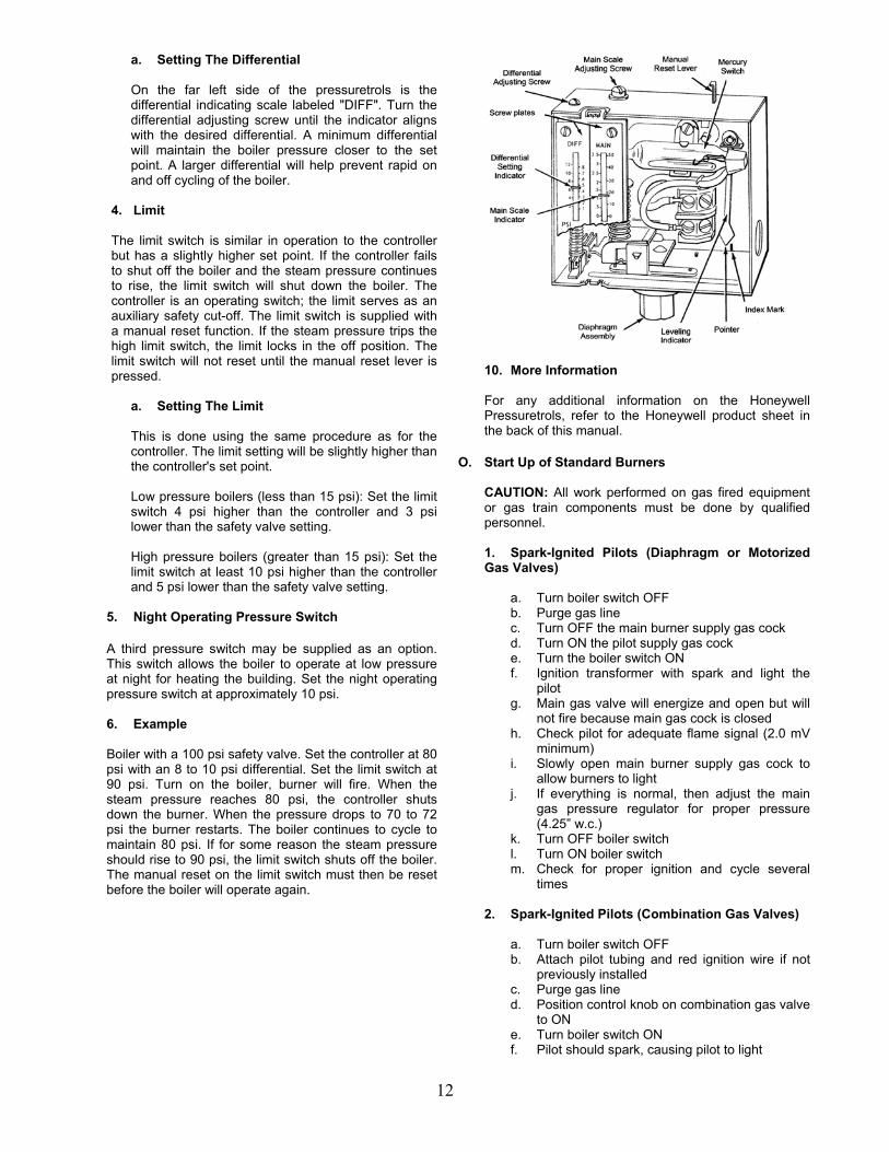
a. Setting The Controller
On the left side of the pressuretrol is the set point indicating scale labeled "MAIN". Turn the main scale adjustment screw until the set point indicator aligns with the desired operating pressure. Turn screw clockwise to increase pressure, counterclockwise to decrease pressure.
3. Differential When the boiler pressure reaches the main set point the controller shuts off the burner. The pressure must drop by a set amount before the controller will turn on the burner again. This amount is called the differential. The differential is adjustable.
12
a. Setting The Differential On the far left side of the pressuretrols is the differential indicating scale labeled "DIFF". Turn the differential adjusting screw until the indicator aligns with the desired differential. A minimum differential will maintain the boiler pressure closer to the set point. A larger differential will help prevent rapid on and off cycling of the boiler.
4. Limit The limit switch is similar in operation to the controller but has a slightly higher set point. If the controller fails to shut off the boiler and the steam pressure continues to rise, the limit switch will shut down the boiler. The controller is an operating switch; the limit serves as an auxiliary safety cut-off. The limit switch is supplied with a manual reset function. If the steam pressure trips the high limit switch, the limit locks in the off position. The limit switch will not reset until the manual reset lever is pressed.
a. Setting The Limit
This is done using the same procedure as for the controller. The limit setting will be slightly higher than the controller's set point. Low pressure boilers (less than 15 psi): Set the limit switch 4 psi higher than the controller and 3 psi lower than the safety valve setting. High pressure boilers (greater than 15 psi): Set the limit switch at least 10 psi higher than the controller and 5 psi lower than the safety valve setting.
5. Night Operating Pressure Switch A third pressure switch may be supplied as an option. This switch allows the boiler to operate at low pressure at night for heating the building. Set the night operating pressure switch at approximately 10 psi. 6. Example Boiler with a 100 psi safety valve. Set the controller at 80 psi with an 8 to 10 psi differential. Set the limit switch at 90 psi. Turn on the boiler, burner will fire. When the steam pressure reaches 80 psi, the controller shuts down the burner. When the pressure drops to 70 to 72 psi the burner restarts. The boiler continues to cycle to maintain 80 psi. If for some reason the steam pressure should rise to 90 psi, the limit switch shuts off the boiler. The manual reset on the limit switch must then be reset before the boiler will operate again.
10. More Information For any additional information on the Honeywell Pressuretrols, refer to the Honeywell product sheet in the back of this manual.
O. Start Up of Standard Burners CAUTION: All work performed on gas fired equipment or gas train components must be done by qualified personnel.
1. Spark-Ignited Pilots (Diaphragm or Motorized Gas Valves)
a. Turn boiler switch OFF b. Purge gas line c. Turn OFF the main burner supply gas cock d. Turn ON the pilot supply gas cock e. Turn the boiler switch ON f. Ignition transformer with spark and light the
pilot g. Main gas valve will energize and open but will
not fire because main gas cock is closed h. Check pilot for adequate flame signal (2.0 mV
minimum) i. Slowly open main burner supply gas cock to
allow burners to light j. If everything is normal, then adjust the main
gas pressure regulator for proper pressure (4.25” w.c.)
k. Turn OFF boiler switch l. Turn ON boiler switch m. Check for proper ignition and cycle several
times 2. Spark-Ignited Pilots (Combination Gas Valves)
a. Turn boiler switch OFF b. Attach pilot tubing and red ignition wire if not
previously installed c. Purge gas line d. Position control knob on combination gas valve
to ON e. Turn boiler switch ON f. Pilot should spark, causing pilot to light

13
g. When pilot flame is proven, main burners will light
h. Adjust valve pressure to 4.25” w.c. i. Consult valve pamphlet in back of manual for
more detailed instructions j. Cycle boiler ON and OFF several times
3. Thermocouple Pilots (Diaphragm or Motorized
Gas Valves)
a. Turn boiler switch OFF b. Attach pilot tubing and thermocouple if not
previously installed c. Purge gas line d. Turn OFF the main burner supply gas cock e. Turn ON the pilot supply gas cock f. Locate pilot switch control knob and turn to
PILOT g. Light pilot while holding knob, then release.
Pilot should stay on. Refer to specific instructions on pilot switch literature in back of manual.
h. Turn boiler switch ON i. With pilot lit, slowly open main burner supply
gas cock to allow burners to light j. Adjust main pressure regulator for proper
pressure (4.25” w.c.) k. Turn OFF boiler switch l. Turn ON boiler switch m. Check for proper ignition and cycle several
times 4. Thermocouple Pilots (Combination Gas Valves)
a. Turn boiler switch OFF b. Attach pilot tubing and thermocouple if not
previously installed c. Purge gas line d. Turn boiler switch ON e. Position control know on valve to PILOT and
hold down f. Light pilot and hold knob until thermocouple
heats up. If, after releasing knob, the pilot stays on, turn knob to ON position. Burners should light
g. Adjust valve pressure to 4.25” w.c. h. Consult combination gas valve information
pamphlet in back of manual for more detailed instructions
i. Cycle boiler on and off several times For warranty validation, complete start up check list (included with boiler) and return it to Lattner. Failure to return check list may void warranty.
5. Check for Gas Leaks Brush a soapy water solution on each connection in the main gas and pilot gas lines. Look for bubbles. If there are any gas leaks, shut off the main gas supply and fix any leaks before continuing. Repeat steps 1 through 4. Do not use a match or other types of fire to locate a gas leak. 6. Adjust The Burners
Atmospheric draft burners can only be properly set up by using combustion test equipment. Adjust air shutter (on each individual burner) and gas pressure regulator until burner objectives below are satisfactorily met. 7. Burner Tuning Objectives
The following measures are approximations only. Data may vary by location, environment, fuel, gas pressure, BTU content and more. Refer to burner manual for more specific instructions, including low-NOx burner instructions for California and Texas.
Constituent Value
Gas Supply Pressure 4.25” w.c. (minimum) Manifold Pressure 3.25” w.c. (minimum)
O2 4.5% to 6.5% CO2 8% to 10% CO Less than 100 ppm NOx Less than 60 ppm
Stack Temperature 400°F to 475°F Efficiency 78% to 82%
8. Pressuretrols Allow the boiler to reach its operating pressure. Check the pressuretrols to be certain they’re are set as described and functioning properly.
9. Level Controls Make certain the level control feeds water into the boiler and maintains a proper water level.
10. Odor It is normal for a new boiler to give an odor when it first fires. This odor will generally go away within two days.

14
Section II: Boiler Care CAUTION: Read and follow all instructions before servicing any boiler.
A. General The life expectancy of any boiler will depend on the routine care given to the boiler. The condition of the water inside the boiler is the most important factor in determining the life of the boiler. The new boiler must be cleaned, proper water treatment must be used over the life of the boiler, and a regular blowdown schedule must be followed. To ensure continuous reliable operation, it is also important that the water feed system be maintained, the burners operate correctly, and the boiler be inspected periodically. B. New Boiler Clean Out
1. Purpose
Regardless of the care used in the manufacture of steel boilers, a certain amount of oil, grease and pipe dope will still be in the boiler when shipped from the factory. Oil in a boiler can cause water to foam and bounce. This creates an unstable water line and causes water to carry over in the steam lines. To remove oil and grease from a new boiler, use the supply of Lattner Boiler Compound sent with the boiler. 2. Directions When installation is complete and boiler has been filled with water, remove the safety valve or use any capped or plugged opening above the water line. Pour in a mixture of Lattner Boiler Compound with water. Follow instructions on the label of the boiler compound and use initial dose as outlined. Fire the boiler and maintain steam pressure of at least 10 psi for a minimum of two hours. This permits the boiler compound to cook and loosen the oil and grease from all metal surfaces. Then shut off the boiler switch, allowing the boiler to cool for one hour and the steam pressure to drop to 0 psi. Open the blowdown valve to the wide open position allowing all water and steam to be blown out of the boiler. Allow boiler to cool to approximately room temperature before filling with cool water. When using a condensate return system with a boiler, it is advisable to waste all of the condensate for the first day or two. This will keep the oils not taken care of by the boiler compound from going back through the pump and into the boiler. If this is not possible then the new boiler clean out procedure becomes imperative. NOTE: Never fill a hot, empty boiler with cold water.
C. Water Conditions 1. Oxygen Scavenging Generally, boiler feedwater will contain oxygen and dissolved minerals. Inside the boiler, the heat will cause the oxygen to separate from the water.
The oxygen will then attack exposed metal surfaces. This leads to corrosion and localized pitting of the metal.
3. Scale Deposits As the water boils, the dissolved minerals will separate from the water and attach to the boiler shell forming scale deposits. Scale will deposit on all surfaces below the water line. Scale deposits will plug the piping and damage the controls. Layers of scale on the boiler shell act as an insulator, preventing heat transfer to the water. This will lower the boiler efficiency and cause the boiler shell to retain heat. Overheating the boiler shell will cause permanent damage to the pressure vessel. Scale deposits inside the boiler can retain enough heat to cause the pressure to continue to rise after the burner is shut off. The pressure may rise enough to lift the safety valve.
D. Water Treatments & Chemicals
1. Purpose of Water Treatment Water treatment chemicals are added to the boiler water to prevent the damaging effects of scale and oxygen corrosion. A complete chemical treatment program must also control the pH level in addition to providing both an oxygen scavenger and control of dissolved solids. The chemicals react with the dissolved solids and dissolved oxygen. This prevents the solids and the oxygen from attacking the boiler.
2. Selecting Water Treatment The boiler feedwater should always be tested by a competent water treatment company that can analyze the boiler water and recommend the best water treatment program for the boiler based on water quality. Some water treatment companies will ask for more samples after the boiler has been in use, to make sure that the water treatment used is adequate. There are several competent water treatment companies that can test, analyze, recommend and supply a boiler feedwater treatment program.
E. Water Softener
A water softener by itself is not a complete treatment program. A softener controls a substantial portion of the dissolved solids. However, it does not remove dissolved oxygen or control pH level. Never use zero grain soft water without additional chemical treatment. Whenever a softener is used, chemical treatment is still necessary for oxygen scavenging and controlling pH.

15
F. Foaming, Bouncing, & Carryover 1. Causes of Foaming
It is normal for the water line of Lattner boilers to fluctuate about one inch. However, excessive foaming and bouncing (an unstable water line) can be caused by several different conditions. The presence of oil or grease in the boiler water will cause serious foaming. Foaming can also be caused by excessive concentrations of boiler water solids. A third cause is excessive alkalinity (high pH level). Water that’s too soft will also cause the water level to bounce.
2. New Boiler Foaming
In a new boiler, foaming has two primary causes. Oil from the steam piping and the boiler metal has accumulated at the water line. Secondly, Lattner clean-out compound contains trisodium phosphate. This must be thoroughly flushed out of the boiler. Trisodium phosphate, if left in the boiler, will raise the alkalinity, causing foaming.
3. Carryover
Carryover (often called priming) is small droplets of water leaving the boiler with steam. Foaming, as described before, is a key cause of carryover. If the foaming problem is eliminated, the carryover should stop as well. If the system uses steam faster than the boiler can make steam, water carryover may occur as well. Be certain that all steam traps function properly, all piping is insulated, there are no leaks in the steam piping, and the burner combustion is set properly.
G. Water Treatment Summary
These are general guidelines for water treatment. Lattner is not a water treatment company and cannot make specific recommendations for each boiler installation. To ensure proper operation and extend the life of the boiler, a complete water treatment program must be used. Contact a qualified company with experience in this field to provide a treatment program for your installation. Insufficient or too much chemical treatment can damage your boiler. The following are guidelines for boiler water quality:
Constituent Value pH 8.5 to 10
Total Dissolved Solids 2,000 ppm or 116.8 grains maximum.
Oxygen 0 ppm Alkalinity Less than 300 ppm Chloride Less than 500 ppm
Sodium Phosphate Less than 100 ppm
H. Blowdown
1. Purpose of Blowdown The boiler and the boiler level controls should be blown down at least DAILY.
Blowdown removes a portion of the water in the boiler in order to reduce the amount of dissolved solids. Blowdown will also remove some of the loose deposits that may be in the boiler.
2. Blowdown Instructions The boiler may be blown down at any pressure, provided the blowdown piping is piped to a safe location (see Installation Instructions). To blowdown, open the boiler bottom blowdown valve (see assembly print) to the fully open position. Watch the sight glass. When the boiler water level drops about one inch, close the blowdown valve. Lattner recommends 30 psi for high pressure boilers. NEVER blowdown a hot boiler to a level where no water is visible in the sight glass.
3. Control Blowdown Scale can also deposit in the water level controls and piping, just as it can deposit in the boiler. The McDonnell Miller level control and auxiliary low water cut-off water column MUST also be blown down daily. If scale blocks these controls or the piping connected to them, the boiler may dry fire. Dry-firing the boiler will permanently damage the boiler shell.
I. Feedwater System
1. General
A boiler cannot operate without water. For proper operation, the boiler must have a reliable water supply.
2. Pump Cavitation Always use spring-loaded check valves in the feedwater piping. Swing check valves (even when new) are not suitable for boiler feed applications. A bad check valve will allow hot water from the boiler to back-feed to the pump. When the pump starts, this water flashes to steam. This condition, known as cavitation, causes the pump to sound like there are ball bearings in the water and prevents the pump from working properly, especially when the boiler pressure rises. Bad steam traps may also cause the pump to cavitate. Bad traps allow steam to return to the condensate tank and heat the water in the tank. As the water temperature gets above 180° F, cavitation becomes more likely and prevents the pump from working properly. 3. Check Valves & Steam Traps
To check for bad steam traps or check valves, look at the vent pipe from the condensate return tank. If there is an abnormally high steam flow from the vent, either the traps or check valves are leaking. A thermal sensor may be used to help detect which traps are malfunctioning.

16
J. Burner Adjustment
1. Danger Only competent personnel familiar with forced draft burners and having proper test equipment to measure burner input and analyze flue gases should attempt adjusting the burner. Refer to the burner manual for proper settings of the forced draft burner.
2. Insufficient Air A properly adjusted burner will burn with an orange-blue flame. If the flame burns brilliant yellow, incomplete combustion is occurring. A yellow flame will deposit soot on the boiler heating surfaces and decrease efficiency. A yellow flame in general terms is caused by too much gas or too little air. Check burner adjustment, air supply to the room, proper gas pressure, draft conditions and the actual gas input according to the gas meter. 3. Excess Air In adjusting the burner air shutters, it is also important not to open them too far. Too much air will cause the burners to backfire when lighting. When burners backfire, they frequently extinguish the pilot flame. This will shut down the boiler. Additionally, when there is excess combustion air, efficiency declines. Heat is wasted warming the excess air instead of making steam.
K. Sight Glass 1. Maintenance The sight glass and water gauge set must be properly maintained in order to observe the boiler water level. Open the bottom drain cock (on the lower sight glass fixture) periodically to flush scale and sediment out of the sight glass. 2. Regular Placement
Replace the sight glass about every six months with new gaskets and brass washers. The continual movement of water through the water gauge set wears the sight glass. The combined effects of wear and high pressure cause small cracks to develop in the sight glass over a period of time. Eventually the sight glass will shatter. This is avoided by replacing the sight glass regularly.
3. Gaskets & Washers
When installing a new sight glass, also replace the gaskets and brass washers. If the brass washers are not in place, the gasket will twist, causing the glass to break.
4. Proper Installation
Always be certain the sight glass is cut to proper length. Make sure the fixtures are plumb. If these two conditions are not checked, the glass may crack.
L. External Inspections
1. Maintenance External inspections are routine observations of the visible portions of the boiler. By noticing the normal boiler operation, many problems can be detected before they become serious. 2. Piping Check the piping for leaks. This includes steam pipes, condensate pipes, feedwater pipes, blowdown pipes and all fittings on the boiler. If leaks are found, tighten the fittings or connections. If the pipe threads show extensive corrosion, replace the section of pipe. Remember, NEVER use galvanized pipe for a steam system or for condensate lines. 3. Dust & Debris If dust, lint, or other debris collect on and around the boiler, then use pressurized air or a rag to clean the exterior surfaces. Also, it is very important to remove dust and debris that accumulate inside the boiler panel box. When working in and around the panel box always shut the power off at the circuit breaker or disconnect switch (do not use the boiler switch). Use an air hose to blow out the panel box and controls. 4. Safety Valve Check that steam is not leaking from the safety valve. If the safety valve is not seating properly, then replace it with a new valve. 5. Level Controls
When making an external boiler inspection, it is also necessary to inspect the McDonnell Miller and auxiliary low water cut-off level controls. Disassemble the McDonnell Miller control per instructions in the Maintenance section. Check for scale build-up in the float chamber, around the float ball and the float rod. Check the float for leaks. Hold the float completely submerged in a bucket of water and look for air bubbles. If the float leaks or is damaged, it must be replaced. Remove the auxiliary low water cut-off probe and remove any scale that has deposited on the probe. Important: Inspect and clean all interconnecting piping on the auxiliary low water cut-off and the McDonnell Miller. 6. Surface Rust Occasionally sheet metal surfaces will rust, especially near the stack. Water, a normal product of combustion, and the high temperatures present will cause rust. Perchloroethylene, used in dry cleaning, will accelerate corrosion. Check the entire length of the stack to be sure there is no leakage of combustion gases. Any rust appearing on the boiler jacket will only affect the boiler's appearance and should not harm the boiler operation.
17
M. Internal Inspections
1. Purpose of Inspections
Internal boiler inspections are required to check the structural integrity of the boiler shell and look for scale accumulations inside the boiler. 2. New Boiler Inspection Make the initial inspection of a new boiler within 30 days of start-up. Depending on the condition of the boiler at this time, have a second inspection in six months or less. The results of these internal inspections can be used to set a time interval for future internal inspections. 3. In Service Boilers The time between inspections will vary from 180 days to one year. This depends on the amount and the quality of the boiler feedwater, and also on how the boiler is being used. If the boiler uses large quantities of untreated hard water, the boiler may need to be inspected every 60 days. If the boiler uses minimal quantities of make-up water (i.e., closed loop systems) and the water is treated, the boiler may need to be inspected only once a year. Many state and/or city codes require annual internal boiler inspections.
4. Gaskets The hand hole gaskets and the McDonnell Miller head gasket must be replaced after each internal inspection. If any leaks are present around the gasket surfaces, replace the gasket immediately. High pressure water and steam leaks will erode the metal surfaces and cause damage to the boiler which will require expensive repairs. Keep a full set of hand hole gaskets and a McDonnell Miller head gasket in stock at all times. 5. Sight Glass A sight glass with gaskets and washers should be kept in stock. Replace the sight glass with new gaskets and washers on a regular basis. 6. Thermocouples For boilers with standing pilots, keep a thermocouple in stock at all times. Lattner uses nickel-plated thermocouples to withstand high temperatures. Thermocouples for water heaters are NOT adequate substitutes. 7. Routine Service These standard maintenance items are considered routine and are not covered under warranty.

18
Section III: Maintenance
WARNING: All maintenance procedures must be followed completely by competent personnel familiar withboilers and boiler accessories.
CAUTION: Read and follow all instructions thoroughly before working on any boiler equipment. NOTE: Certain maintenance items concerning specific components may be found in the product literaturespecifications section of this manual.
A. Daily Blowdown The boiler and controls may be blown down at any pressure but the blowdown lines must be piped to a safe location. Lattner recommends blowing down at 30 psi for high pressure boilers.
1. Boiler Blowdown
Turn the boiler blowdown valve to the full open position.
Watch the sight glass. Let the water drop one inch in the sight glass. Approximately 10 to 12 seconds.
Shut the boiler blowdown valve.
2. McDonnell Miller/Water Column Drain
Turn the McDonnell Miller drain valve to the full open position.
Leave the valve open for 3 to 5 seconds. Shut the water column drain valve.
3. Auxiliary Low Water Drain (if applicable)
Turn the auxiliary low water column drain valve to the full open position.
Leave the valve open for 3 to 5 seconds. Shut the low water column drain valve.
B. Weekly Maintenance
1. Check the sight glass for excessive wear or leaks. 2. Test the McDonnell Miller and auxiliary low water
cut-off for proper operation. By opening the blowdown valves with the boiler firing, the burners must shut off during this test. If the burners do not shut off, the control may require immediate servicing.
3. Drain the sight glass. 4. Visually inspect the boiler and water feed system for
any water or steam leaks in the piping. 5. Check the vent pipe from the condensate return tank
for excessive steam loss. This would indicate bad steam traps or check valves.
C. General Maintenance
1. Do the following every 6 to 12 months depending on water quality:
Remove hand hole plate and clean inside
boiler. Reassemble each hand hole with a new
gasket. Clean McDonnell Miller float chamber.
Reassemble the operating mechanism with a
new head gasket. Clean scale off the auxiliary low water cut-off
probe. Clean the interconnecting piping between the
boiler and McDonnell Miller. Clean the interconnecting piping between the
boiler and auxiliary low water column if applicable.
2. Open the boiler for a complete internal inspection
at least once a year. 3. Replace the sight glass with gaskets and washers
every six months or less if signs of wear appear. 4. Rebuild or replace the check valves in the water
feed line at least once a year. Always use spring-loaded check valves.
5. Inspect the pilot burner and flame scanner for soot
or dirt accumulations.

19
D. Table 1: Recommended Testing Schedule
Item Frequency Responsibility Remarks Gauges and Sight Glass Daily Operator Make visual inspection and record readings in a log. Instrument and Boiler Settings Daily Operator Make visual check against manufacturer’s
recommended specifications. Refer to product literature sheets.
Low Water Fuel Cut-Off Monthly Operator Refer to manufacturer’s instructions. Pilot and Main Fuel Valves Monthly Operator Make visual inspection. Flame Failure Response Time Monthly Operator Close manual fuel valve supply. Check safety shut-
off timing. Log results. Flame Signal Strength Monthly Operator If appropriate equipment is installed to measure
flame signal, read and log results for pilot flame. Notify service organization if readings are high, low, or fluctuating.
Hand Hole Plates Monthly Operator Visually check for leakage and replace gaskets as necessary.
Firing Rate Control Annually Service Technician Verify BTU input and gas pressure and check with combustion test/analyzer.
Igniter or Pilot Annually Operator Make visual inspection and check flame strength with appropriate equipment.
Flue, Vent, and Stack Annually Operator Make visual inspection and check for proper operation.
Pilot Turndown Test Annually Service Technician Required after any adjustments to pilot or gas pressure.
High Limit Safety Control Annually Service Technician Refer to product literature. Operating Control Annually Service Technician Refer to product literature. Safety Valve As Required Operator In accordance with ASME Boiler and Pressure
Vessel Code, “Recommended Rules for Care and Operation of Heating Boilers”.
20
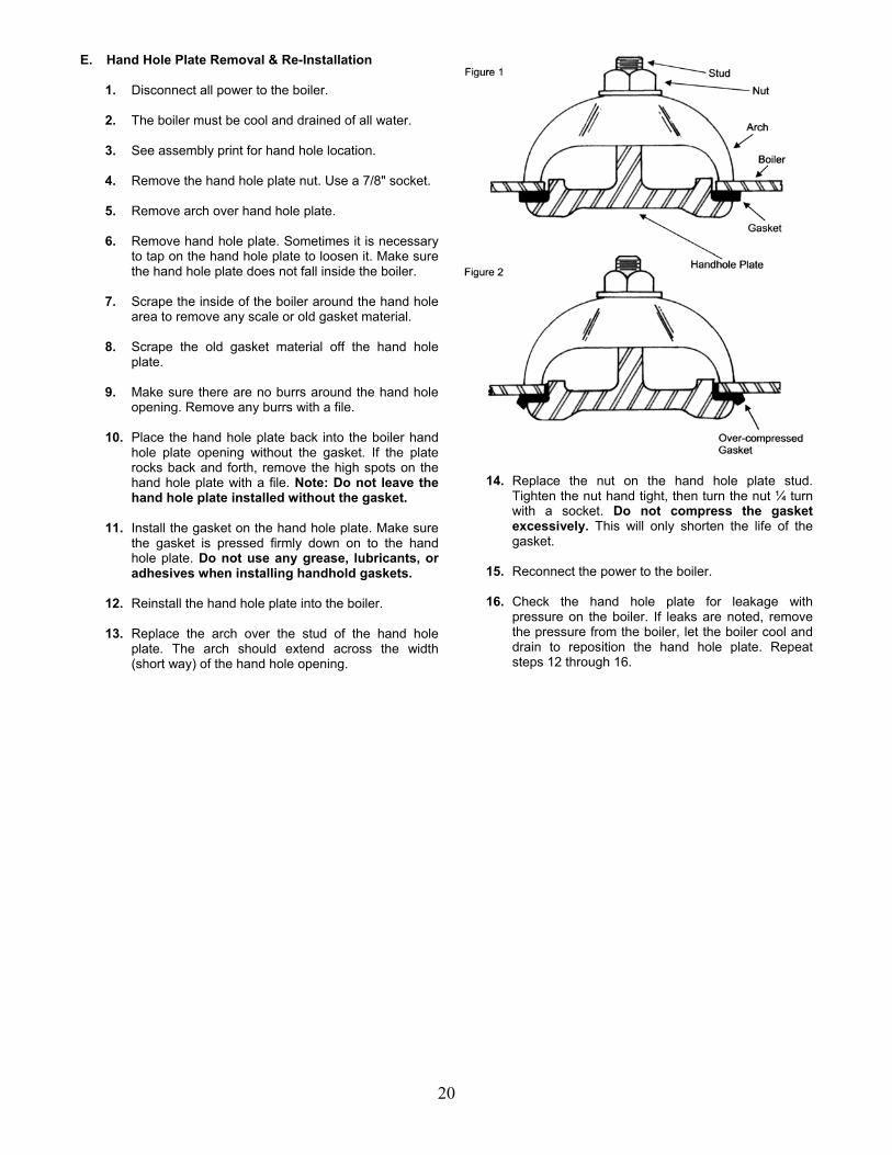
E. Hand Hole Plate Removal & Re-Installation 1. Disconnect all power to the boiler. 2. The boiler must be cool and drained of all water. 3. See assembly print for hand hole location. 4. Remove the hand hole plate nut. Use a 7/8" socket. 5. Remove arch over hand hole plate. 6. Remove hand hole plate. Sometimes it is necessary
to tap on the hand hole plate to loosen it. Make sure the hand hole plate does not fall inside the boiler.
7. Scrape the inside of the boiler around the hand hole
area to remove any scale or old gasket material. 8. Scrape the old gasket material off the hand hole
plate. 9. Make sure there are no burrs around the hand hole
opening. Remove any burrs with a file. 10. Place the hand hole plate back into the boiler hand
hole plate opening without the gasket. If the plate rocks back and forth, remove the high spots on the hand hole plate with a file. Note: Do not leave the hand hole plate installed without the gasket.
11. Install the gasket on the hand hole plate. Make sure
the gasket is pressed firmly down on to the hand hole plate. Do not use any grease, lubricants, or adhesives when installing handhold gaskets.
12. Reinstall the hand hole plate into the boiler. 13. Replace the arch over the stud of the hand hole
plate. The arch should extend across the width (short way) of the hand hole opening.
14. Replace the nut on the hand hole plate stud. Tighten the nut hand tight, then turn the nut ¼ turn with a socket. Do not compress the gasket excessively. This will only shorten the life of the gasket.
15. Reconnect the power to the boiler. 16. Check the hand hole plate for leakage with
pressure on the boiler. If leaks are noted, remove the pressure from the boiler, let the boiler cool and drain to reposition the hand hole plate. Repeat steps 12 through 16.

21
F. Sight Glass Removal & Re-Installation
1. Boiler and pump should be switched off. 2. Boiler should be cool and the water level should be
below the lower water gauge fixture. 3. Close the upper and lower water gauge valves. 4. Loosen both sight glass packing nuts (top and
bottom) with a wrench. 5. Slide glass carefully upward into the upper fixture.
Glass should lift out of the lower fixture. 6. Pull glass down, out of the upper fixture tilting the
glass slightly to clear the lower fixture. Be careful not to break the sight glass when removing.
7. Assemble the new sight glass as shown. ALWAYS
replace the gaskets and brass washers when installing a new sight glass.
8. Slide the new glass into the upper fixture. Glass
should clear the lower fixture and tilt into position. 9. Slide the sight glass down into the lower fixture until
it stops. Equalize the gap between the upper and lower fixtures by lifting the glass approximately 1/8” so it is not resting on the bottom fixture.
10. Tighten the sight glass packing nuts hand tight. 11. Use a wrench to tighten 1/4 turn past hand tight.
NEVER over tighten the sight glass. This will crack the glass and cause it to shatter under pressure.
12. Open the upper and lower gauge valves. 13. Switch on boiler and pump. 14. Do not allow the glass to leak as this will eventually
erode and thin the glass causing it to fail. A bouncing water level or water with an unusual pH or high in mineral content will also erode the inside of the glass.

22
G. McDonnell Miller Servicing
1. Disconnect all power to the boiler. 2. The boiler should be cool and drained of all water
just below the McDonnell Miller control. 3. Make sure all water is drained from the McDonnell
Miller control by opening the control blowdown valve.
4. Disconnect the wiring and conduit connection to the
McDonnell Miller. Tag all wires to ensure they are reconnected properly.
5. Remove the eight bolts holding the operating
mechanism to the McDonnell Miller body. Use a 9/16" wrench or a crescent wrench.
6. It may be necessary to tap near the base of the
operating mechanism to free it from the body. 7. Lift the McDonnell Miller operating mechanism out of
the body. Be careful to avoid damaging the float and float arm which extend into the body of the McDonnell Miller.
8. Carefully scrape the old gasket from the body and
the operating mechanism of the McDonnell Miller. 9. Remove any scale in the McDonnell Miller body.
Always check the operating mechanism for any scale that might be blocking the float or float arm.
10. Check the float for any holes. Hold the float
submerged in a bucket of water and look for any air bubbles coming from the float.
11. Always reassemble the McDonnell Miller operating
mechanism to the body with a new gasket. 12. Reinstall the eight bolts to the operating mechanism.
Draw up the bolts evenly to prevent damage to the gasket, body or operating mechanism. Do not over tighten the bolts.
13. Reconnect the McDonnell Miller per wiring diagram. 14. Reconnect all power to the boiler. 15. Use a steel rod or a hard brush and clean inside of
the piping.
16. Flush out all piping with water after cleaning. 17. Replace all pipe plugs and pipe caps. Tighten with
a wrench enough to prevent water or steam leaks. 18. Reconnect power to the boiler.
H. Cleaning Interconnecting Pipe (McDonnell Miller)
Disconnect all power to the boiler. The boiler must be cool and drained of water below the
level controls. Make sure all water is drained from the McDonnell Miller
or auxiliary low water cut-off control by opening the blowdown valve.
Clean all interconnecting piping by removing the pipe
plugs or pipe caps. Remove all 1" pipe plugs with a 13/16" wrench or a crescent wrench. Remove the pipe caps with a pipe wrench.
23
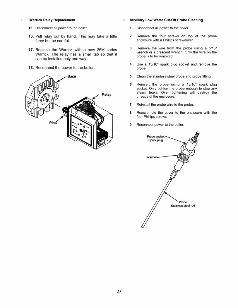
I. Warrick Relay Replacement
15. Disconnect all power to the boiler. 16. Pull relay out by hand. This may take a little
force but be careful. 17. Replace the Warrick with a new 26M series
Warrick. The relay has a small tab so that it can be installed only one way.
18. Reconnect the power to the boiler.
J. Auxiliary Low Water Cut-Off Probe Cleaning
1. Disconnect all power to the boiler.
2. Remove the four screws on top of the probe enclosure with a Phillips screwdriver.
3. Remove the wire from the probe using a 5/16"
wrench or a crescent wrench. Only the wire on the probe is to be removed.
4. Use a 13/16" spark plug socket and remove the
probe.
5. Clean the stainless steel probe and probe fitting.
6. Reinsert the probe using a 13/16" spark plug socket. Only tighten the probe enough to stop any steam leaks. Over tightening will destroy the threads of the enclosure.
7. Reinstall the probe wire to the probe.
8. Reassemble the cover to the enclosure with the
four Phillips screws.
9. Reconnect power to the boiler.

24
Section IV: Troubleshooting
WARNING: All troubleshooting procedures must be followed completely by competent personnel familiar with boilers and accessories. CAUTION: Read and follow all instructions before troubleshooting any boiler equipment. A. Normal Operation All Lattner atmospheric gas-fired boilers follow the same operating sequence:
1. Turn the pump switch ON. 2. McDonnell Miller pump control turns on the pump or
solenoid water valve. 3. Pump or solenoid valve fills boiler. 4. McDonnell Miller shuts off the pump or solenoid
water valve when water is at normal operating level. 5. Turn boiler switch to the ON position. 6. Gas valve opens and main burners light. 7. Boiler pressure will rise to the pressure controller’s
set point. The then controller will shut off the gas valve.
8. When the boiler calls for water, the McDonnell Miller
level control will turn on the pump or solenoid water valve.
9. If the pump cannot fill the boiler, the McDonnell
Miller low water cut-off will shut down the boiler. If the McDonnell Miller does not shut down the boiler, the auxiliary low water cut-off will shut down the boiler.
10. If the boiler has optional controls, refer to the wiring
diagram.
B. Basic Service Tools
The following basic equipment will aid in troubleshooting Lattner boilers. Not all equipment is needed for every repair:
1. Schematic diagram of the boiler 2. Volt/ohm meter 3. Ammeter 4. Gas pressure gauge 5. Continuity tester 6. Flue gas analyzer 7. Carbon monoxide sampler
C. Before You Begin Before you begin any troubleshooting procedures, check the following:
1. Make sure the pilot is lit. 2. Be certain boiler switch is on and that there are 115
volts supplied to the boiler control circuit. 3. Be certain pump switch is ON and check for proper
pump voltage and phase if different from boiler circuit.
4. Check if breaker is tripped or if fuse is blown. 5. Make sure there is water in the boiler. 6. Be certain manual gas cock is open and that gas is
supplied to the boiler. 7. Be certain that all manual resets have been
pushed.
Note: All Lattner boiler controls are wired in series. The boiler operating controls and limits form a series circuit. When all switches close, the boiler should fire.

25
Possible Boiler Problems Possible Causes Boiler and pump switch are ON, pump does not run and low water level in boiler.
1. Circuit breaker is tripped or fuse is blown. 2. McDonnell Miller piping is plugged. 3. McDonnell Miller float is stuck. 4. McDonnell Miller is wired incorrectly. 5. Pump or solenoid water valve is wired incorrectly.
Pump runs but does not maintain water level in boiler.
1. Valve between boiler pump and boiler is closed. 2. Bad check valve. Always replace check valves with spring-loaded check valves. 3. Bad steam trap(s). 4. Feedwater temperature is too high (pump is cavitating). 5. Strainer is plugged. 6. Pump isolation valve is closed. 7. No water supplied to pump.
Pump or solenoid overfills boiler. 1. Solenoid water valve is not seating properly.
2. McDonnell Miller float operating incorrectly (snap switches “sticking”). 3. McDonnell Miller mercury tube is malfunctioning. 4. McDonnell Miller is wired incorrectly. 5. Pump is wired incorrectly.
Boiler takes excessive time to reach pressure.
1. Burner is improperly adjusted. 2. Improper gas pressure or insufficient supply of gas to boiler. 3. Boiler flue passages need to be cleaned. 4. Scale build-up inside boiler. 5. Gas valves not operating properly. 6. Pump not feeding enough water to the boiler.
Limit switch always shuts down boiler.
1. Operating pressure switch is set higher than limit switch. 2. Scale build-up inside of boiler. 3. Operating pressure switch (Honeywell “Controller”) is not operating correctly.
Boiler shuts down on auxiliary low water cut-off.
1. Pump switch is turned OFF. 2. Probe wired incorrectly. 3. Probe has scale, dirt, or debris on it. 4. Probe not seated in probe socket properly. 5. Auxiliary level control relay wired incorrectly. 6. Foaming problem in boiler (possible chemical over treatment). 7. Water in boiler is too soft (possible water softener over treatment). 8. McDonnell Miller primary low water cut-off isn’t operating properly. 9. Pump is not functioning properly. 10. Malfunctioning check valve. Always replace check valves with spring-loaded check
valves. 11. No water supplied to the pump.
Burner fails to start.
1. Bad fuse or switch open on incoming power source or motor overload out. 2. Control circuit has an open control such as operating, limit, or low water cut-off. 3. Reset button on motor or flame safeguard programming control open (push reset
button). 4. Loose or faulty wiring. Tighten all terminal screws. Check wiring against wiring diagram
furnished with burner. 5. Regulator vent plugged.
Occasional lockout for no apparent reason.
1. Re-check microamp or D.C. voltage readings. If sufficient, check gas pressure an air damper setting. Check electrodes setting. If flame rod pilot, flame rod may have to be re-positioned.
2. Check ignition cable and electrode porcelain for damage or breaks which could cause short.
3. Check for loose or broken wires.
Flame Safeguard
For information on Honeywell flame safeguard and relay troubleshooting, refer to Honeywell technical literature number 65-0229-1.

LATTNER BOILER LIMITED WARRANTY A Lattner boiler shell is guaranteed to be constructed in accordance with the ASME Code. An independent ASME boiler inspector inspects the construction of each boiler and: (1) checks mill test reports on all materials used to ensure that the chemical and physical analysis of such materials complies with the ASME Code; (2) inspects each boiler shell during construction to see that workmanship complies with the Code; and (3) witnesses the final hydrostatic test and then places the ASME stamp on the boiler shell and signs an ASME data report certifying the boiler is ASME approved. Lattner warrants the boiler and any other equipment of its manufacture to be free from defects in material and workmanship for one (1) year from the date of shipment from the factory, provided the boiler is operated under the normal use and service for which it was intended, and only if the boiler has been properly installed by a qualified technician in accordance with but not limited to ASME, ANSI, and NFPA Codes and applicable local, state, and national codes. Lattner’s obligation under this Warranty is limited, at Lattner’s option, to replacing or repairing any defective part of the boiler or other equipment it manufactures. No allowance will be made for labor, transportation, or other charges incurred in the replacement or repair of defective parts. Merchandise not manufactured by the Company, supplied in one piece or in component assemblies, is not covered by the above warranty, but the Company will give the Purchaser the benefit of such adjustment as it can make with the manufacturer of such items. Lattner shall not be liable for special, indirect, or consequential damages. Lattner shall not be liable for any loss or damage resulting, directly or indirectly, from the use or loss of use of the boiler. This exclusion from liability includes the Purchaser’s expenses for downtime or for making up downtime, damages for which the Purchaser may be liable to other persons, or damages to property. The remedies set forth in this Warranty are exclusive, and the liability of Lattner with respect to any contract or sale shall not exceed the cost of repair or replacement of the boiler or other equipment manufactured by Lattner. The above Warranty shall not apply to any boiler or other equipment manufactured by Lattner which:
1) has been repaired or altered without Lattner’s written consent; 2) has been altered in any way so as, in the judgment of Lattner, to adversely affect the stability
or reliability of the boiler; 3) has been subject to improper water treatment, scale, corrosion, misuse, negligence, or
accident; 4) has not been operated in accordance with Lattner’s printed instructions or specifications; 5) has been operated under conditions more severe than or otherwise exceeding those set forth
in the specifications for such boiler; or 6) has not been properly installed by a qualified technical in accordance with but not limited to
ASME, ANSI and NFPA Codes and all applicable local, state and national codes. THIS WARRANTY IS EXPRESSLY MADE IN LIEU OF ALL OTHER WARRANTIES, EXPRESS OR IMPLIED. LATTNER MAKES NO WARRANTY OF MERCHANTABILITY OR OF FITNESS FOR ANY PARTICULAR PURPOSE. Purchaser must notify Lattner of a breach of Warranty within thirty (30) days after discovery thereof, but not later than the one-year guarantee period; otherwise, such claims shall be deemed waived. No allowance will be granted for any repairs or alterations made by Purchaser without Lattner’s prior verbal or written consent. Items returned to Lattner must be accompanied by a factory-supplied return goods authorization (RGA). Such authorization may be obtained by calling the factory at 319/366-0778 or by writing to P.O. Box 1527, Cedar Rapids, IA 52406. Lattner neither assumes nor authorizes any person to assume for it any other liability in connection with the sale or use of the boiler or other equipment manufactured by Lattner, and there are no oral agreements or warranties collateral to or affecting this Agreement.
LATTNER BOILER COMPANY Cedar Rapids, IA USA

STANDARD TERMS & CONDITIONS
LIMITATION ON QUOTATION
Unless otherwise stated in the quotation, the quotation will remain valid for a period of thirty (30) days from the date hereof, at which time it will automatically expire unless extended by a signed document issued by the Company, from its headquarters in Cedar Rapids, IA.
EQUIPMENT SELECTION
The Purchasers selection of sizes, types, capacities, and specifications and suitability thereof for the specific application shall be the unshared responsibility of the Purchaser or Purchaser’s representative or consultant.
PRICES
Unless defined otherwise in the quotation, prices are F.O.B. Cedar Rapids, IA – USA, exclusive of freight, storage, off-loading, installation, service, start-up, extended warranty or local delivery charges, if any.
TAXES
Purchaser shall be liable for all Federal, State, and local taxes with respect to the purchase of the equipment proposed, unless exclusively exempted from any taxes and proof thereof is on file with the Company.
PAYMENT
Purchaser shall pay with US funds, the full amount of the invoiced purchase price within 30 (30) days of the Company’s invoice, whether the equipment has shipped or has been delayed through no fault of the Company and subject to approved credit. Beginning thirty (30) days after the invoice date, Purchaser shall pay a late payment charge of two percent (2%) per month, which is an annual rate of 24%, on any unpaid portion of the purchase price. The Company reserves the right to revoke or modify these credit terms.
SHIPMENT
Any shipping date shown in the body of the quotation or order acknowledgement, represents the Company’s approximated schedule as of the date of the quotation, and is subject o change as determined by shop loading if and when this quotation should be realized as an actual sale. The Company shall no incur any liability of any kind for failure to ship on any particular date unless a firm shipping date has been expressly agreed to by an officer of the Company, in a separate written document.
CANCELLATION AND DELAYS
Subsequent to the receipt of Purchaser’s Purchase Order and the Company’s issued order acknowledgement, the Purchaser may not change nor cancel the order in whole or in part, without the written approval and acceptance by the Company of such cancellation or change. The price change to reflect the Company’s cost to implement the change, or to offset costs incurred by the Company in order preparation, engineering, purchasing, and or in actual production of the order in the event of a cancellation. In the event that Purchaser delays shipment of the equipment up the Company’s notice to ship, the equipment shall be place in storage at the Purchaser’s risk and expense, and transfer to storage shall occasion shipment and the order shall be invoice as if shipped.
RETURNS AND RESTOCKING
Equipment may be returned to Lattner at 1411 9th Street SW, Cedar Rapids, IA 52406, only upon prior written authorization of the Company. Consent, if given, will be upon the condition the purchaser assumes all carrier charges, responsibility for damages in transit, and a minimum 15% restocking charge, and the only if the so authorized material is in new and .unused condition and returned within one year from original date of shipment. The credit will be based on the original invoice price or the current price; whichever is lower, less the applicable restocking charge.
SECURITY INTEREST
For the purposes of securing payment, the Company may issue a lien on the equipment, following the invoice 30 days time, and until such time that payment has been received in full. Upon receipt of payment in full, the Company will rescind the lien.
FORCE MAJEURE
In no event shall the Company be liable for loss or damage resulting from any delay or failure to ship or other failure, loss or damage that is the proximate result of any act of government authority, revolution, riot, civil disorder, art of war, delay or default in transportation, inability to obtain materials or facilities from normal sources, fire, flood, act of God, or any cause not within the reasonable control of the Company. The Company may, without causing a breach or incurring liability, allocate goods which are in short supply irrespective of the reasons therefore among customers in any manner which the Company in its sole discretion deems advisable. If an event occurs that is beyond the control of the Company, and that even delays the Company’s performance and causes its cost of production to increase because of the delay, the Company may pass such increased cost(s) on to the Purchaser.
DAMAGE LIMITATION
Under no circumstance shall the Company be held liable for any loss of profits, down time, or any incidental or consequential damages of any kind with respect to its products or the transaction by which its products are sold.
WARRANTY AND PERFORMANCE
Products shall be warranted in accordance with the Company’s standard warranty statement, form No. 2-98. The Company’s warranty shall be voiced by any abuse, misuse, neglect, unauthorized modification or service, lack of maintenance and service, or use not in accordance with the Company’s instructions. Warranty shall also be voided if water treatment has not been provided or by improper start-up of the equipment. The Company’s sole warranty statement and this paragraph contain the Company’s sole warranty and the Company makes no implied warranty, and there is no implied warranty of merchantability or fitness for any particular purpose.
SERVICE
Unless otherwise noted herein, the cost of the equipment does not include service or installation. All services performed by the Company are subject to purchaser’s payment of the Company’s prevailing charges plus necessary travel and living expenses. Whenever service is quoted, please refer to Lattner’s Service Policy for specific details.
EXCLUSION OF OTHER TERMS
This constitutes an offer on behalf of Lattner Boiler Manufacturing (the Company); to sell the goods described in the quotation, exclusively on the terms and conditions stated. Acceptance of this by the Purchaser is hereby expressly limited to these Terms and Conditions and shall be applicable to any order issued by the Purchaser unless other terms have been agreed to in a written document issued by the Company.
GOVERNING LAW
The transaction with respect to the goods, which are subject hereof, shall be governed by the interpreted and construed in accordance with the laws of the State of Iowa. The Courts in the State of the Iowa. The Courts in the State of Iowa will have the sole jurisdiction over any claim arising under this contract of sale.
ASSIGNMENT
All sales as evidenced by the Company’s acknowledgement hall be binding up on and inure to the benefit of the Purchaser and the Company and their respective heirs, successors, or assigns.
LATTNER BOILER COMPANY
Cedar Rapids, IA USA

Lattner Boiler Company Instruction Manual – WLF Models
February 2005
48
Easy Topog-E® Boiler Installation Instructions 1. Remove old gasket and thoroughly clean the surface on boiler and on cover plate.
Sometimes it is necessary to buff each surface. 2. Place Topog-E® Gasket on handhole cover plate. Be sure the gasket is pushed down
tight on the plate. Do not use any grease, lubricant, or adhesive.
3. After cover plate is in boiler and gasket is in place, make one last cleaning swipe of the
mating surface in the boiler. Use a rag wrapped around your finger.
4. Set crab, then center plate in opening and tighten nut enough to give a snug fit. Then,
snug up with 1/4 turn of wrench.
SPECIAL NOTES: • If gasket leaks while pressure is being built up, tighten only enough to stop leakage.
Never over-compress a gasket.
• Gaskets on the bottom of a boiler shell are usually hard to install without leaking because particles of scale or sand tend to run down onto the mating surface between the time the surface is cleaned and the handhole cover plate is put into place ready

Lattner Boiler Company Instruction Manual – WLF Models
February 2005
49
to be tightened. When this happens, drain the boiler again and start over, or expect to replace the gasket in a very short time.
• As pressure builds up in the boiler the bolt and crab will loosen. It takes some time for the gasket to reach its ultimate compression, so the operator should watch this for several days and keep the bolt tight until it no longer loosens. This is especially true if the boiler is operated intermittently; i.e., shut off at night to allow pressure to drop. In this case, vacuum pressure in the boiler would suck the cover plate in and allow the water to leak out of the boiler.
• Re-using gaskets after they have been in service is not recommended!
Topog-E® Bolt Gaskets (when required) should be used with Topog-E® Handhole Gaskets. Topog-E® Gaskets are sold for use in steam, water, air, and other selected applications only. Recommendations for use of Topog-E Gaskets are based on tests believed to be reliable and on actual customer experience. Since their installation and use is beyond our control we cannot guarantee the results, whether or not such use is in accordance with directions. We disclaim any responsibility.
1224 North Utica
Tulsa, OK 74110-4682 1-800-587-7123 918-587-6649
Fax: 918-587-6961 [email protected]

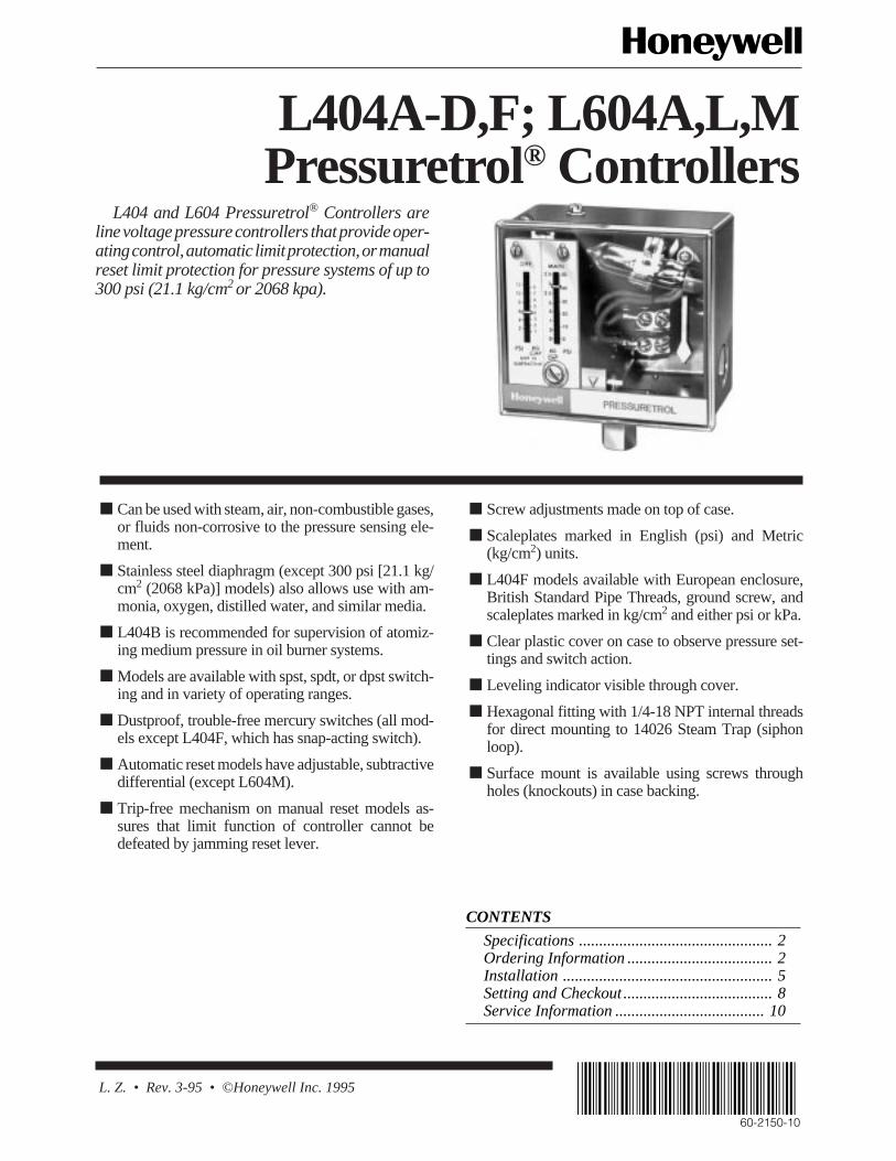
L. Z. • Rev. 3-95 • ©Honeywell Inc. 1995
L404A-D,F; L604A,L,MPressuretrol® Controllers
CONTENTS
Specifications ................................................ 2Ordering Information .................................... 2Installation .................................................... 5Setting and Checkout ..................................... 8Service Information ..................................... 10
L404 and L604 Pressuretrol® Controllers areline voltage pressure controllers that provide oper-ating control, automatic limit protection, or manualreset limit protection for pressure systems of up to300 psi (21.1 kg/cm2 or 2068 kpa).
■ Screw adjustments made on top of case.
■ Scaleplates marked in English (psi) and Metric(kg/cm2) units.
■ L404F models available with European enclosure,British Standard Pipe Threads, ground screw, andscaleplates marked in kg/cm2 and either psi or kPa.
■ Clear plastic cover on case to observe pressure set-tings and switch action.
■ Leveling indicator visible through cover.
■ Hexagonal fitting with 1/4-18 NPT internal threadsfor direct mounting to 14026 Steam Trap (siphonloop).
■ Surface mount is available using screws throughholes (knockouts) in case backing.
■ Can be used with steam, air, non-combustible gases,or fluids non-corrosive to the pressure sensing ele-ment.
■ Stainless steel diaphragm (except 300 psi [21.1 kg/cm2 (2068 kPa)] models) also allows use with am-monia, oxygen, distilled water, and similar media.
■ L404B is recommended for supervision of atomiz-ing medium pressure in oil burner systems.
■ Models are available with spst, spdt, or dpst switch-ing and in variety of operating ranges.
■ Dustproof, trouble-free mercury switches (all mod-els except L404F, which has snap-acting switch).
■ Automatic reset models have adjustable, subtractivedifferential (except L604M).
■ Trip-free mechanism on manual reset models as-sures that limit function of controller cannot bedefeated by jamming reset lever.
60-2150-10
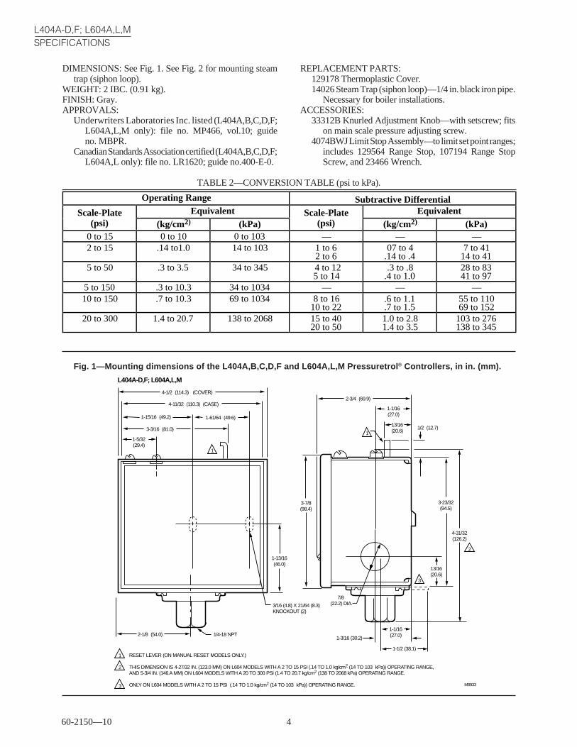
60-2150—10 4
L404A-D,F; L604A,L,MSPECIFICATIONS
Fig. 1—Mounting dimensions of the L404A,B,C,D,F and L604A,L,M Pressuretrol ® Controllers, in in. (mm).
L404A-D,F; L604A,L,M
1/4-18 NPT
1
2
1
2
3
1
3
4-1/2 (114.3) (COVER)
4-11/32 (110.3) (CASE)
3/16 (4.8) X 21/64 (8.3)KNOCKOUT (2)
1-15/16 (49.2)
3-3/16 (81.0)
1-5/32(29.4)
2-1/8 (54.0)
2-3/4 (69.9)
1-61/64 (49.6)
1-13/16(46.0)
1-1/16(27.0)
13/16(20.6)
1/2 (12.7)
3-7/8(98.4)
7/8 (22.2) DIA.
1-1/2 (38.1)
1-3/16 (30.2)
1-1/16(27.0)
13/16(20.6)
4-31/32(126.2)
3-23/32(94.5)
RESET LEVER (ON MANUAL RESET MODELS ONLY.)
THIS DIMENSION IS 4-27/32 IN. (123.0 MM) ON L604 MODELS WITH A 2 TO 15 PSI (.14 TO 1.0 kg/cm2 (14 TO 103 kPa)) OPERATING RANGE, AND 5-3/4 IN. (146.A MM) ON L604 MODELS WITH A 20 TO 300 PSI (1.4 TO 20.7 kg/cm2 (138 TO 2068 kPa) OPERATING RANGE.
ONLY ON L604 MODELS WITH A 2 TO 15 PSI (.14 TO 1.0 kg/cm2 (14 TO 103 kPa)) OPERATING RANGE. M8933
DIMENSIONS: See Fig. 1. See Fig. 2 for mounting steamtrap (siphon loop).
WEIGHT: 2 IBC. (0.91 kg).FINISH: Gray.APPROVALS:
Underwriters Laboratories Inc. listed (L404A,B,C,D,F;L604A,L,M only): file no. MP466, vol.10; guideno. MBPR.
Canadian Standards Association certified (L404A,B,C,D,F;L604A,L only): file no. LR1620; guide no.400-E-0.
REPLACEMENT PARTS:129178 Thermoplastic Cover.14026 Steam Trap (siphon loop)—1/4 in. black iron pipe.
Necessary for boiler installations.ACCESSORIES:
33312B Knurled Adjustment Knob—with setscrew; fitson main scale pressure adjusting screw.
4074BWJ Limit Stop Assembly—to limit set point ranges;includes 129564 Range Stop, 107194 Range StopScrew, and 23466 Wrench.
TABLE 2—CONVERSION TABLE (psi to kPa).
Operating Range Subtractive DifferentialScale-Plate Equivalent Scale-Plate Equivalent
(psi) (kg/cm2) (kPa) (psi) (kg/cm2) (kPa)0 to 15 0 to 10 0 to 103 — — —2 to 15 .14 to1.0 14 to 103 1 to 6
2 to 6 07 to 4
.14 to .47 to 41
14 to 415 to 50 .3 to 3.5 34 to 345 4 to 12
5 to 14.3 to .8
.4 to 1.028 to 8341 to 97
5 to 150 .3 to 10.3 34 to 1034 — — —10 to 150 .7 to 10.3 69 to 1034 8 to 16
10 to 22.6 to 1.1.7 to 1.5
55 to 11069 to 152
20 to 300 1.4 to 20.7 138 to 2068 15 to 4020 to 50
1.0 to 2.81.4 to 3.5
103 to 276138 to 345

60-2150—10 8
L404A-D,F; L604A,L,MSETTING AND CHECKOUT
SETTINGIn all models, the differential is subtractive from the
main scale set point. The upper operating point is deter-mined by the main scale set point, while the lower operat-ing point is determined by the main scale setting less thedifferential setting. The L404F and L604A (with jumperinstalled), L,M have spdt switching action. Operating pointsare shown in Fig. 10.
Fig. 10—L404 and L604 operating points.
main scale setpoint. They will not automatically return totheir former positions. To reset one of these controllers,wait until the pressure falls to the set point minus thedifferential (Fig. 10). Then depress the manual reset lever(Fig. 11) and release it. The controller will not be reset untilyou release the manual reset lever. This prevents the con-troller from becoming an automatic-reset device if the resetlever is stuck, held in, or tied down.
Fig. 11—Setting a Pressuretrol ® Controller.
Setting and Checkout
MAIN SCALE SETPOINT(SWITCH BREAKS)
SUBTRACTIVEDIFFERENTIAL
DIFFERENTIAL SETTING(SWITCH MAKES)
PRESSURERISE
L404A,C
1
MAIN SCALE SETPOINT(SWITCH MAKES)
SUBTRACTIVEDIFFERENTIAL
DIFFERENTIAL SETTING(SWITCH BREAKS)
PRESSURERISE
L404B,D
1
MAIN SCALE SETPOINT(BREAKS R-B, MAKES R-W)
SUBTRACTIVEDIFFERENTIAL
DIFFERENTIAL SETTING(MAKES R-B, BREAKS R-W)
PRESSURERISE
L404F;L604L,M
1
2
MAIN SCALE SETPOINT(MAKES R1-W, BREAKS R2-B)
SUBTRACTIVEDIFFERENTIAL
DIFFERENTIAL SETTING(BREAKS R1-W, MAKES R2-B)
PRESSURERISE
L604A
1
2
L404C,D AND L604L MANUAL RESET MODELS HAVE A SMALL, FIXEDDIFFERENTIAL. THEY CAN BE MANUALLY RESET WHEN THE PRESSUREFALLS TO THE MAIN SCALE SETPOINT MINUS THE DIFFERENTIAL.
L604M HAS A SMALL, FIXED DIFFERENTIAL OF 3.5 PSI (0.25 kg/cm2) OR 24.1 kPa.) M8942
Adjust the main scale set point for the desired operatingpressure by turning the main scale adjusting screw (Fig. 11)on the top of the case until the main scale setting indicatoris at the desired value. On an L404A,B,F with a 5 to 150 psi(.3 to 10.3 kg/cm2 [34 to 1034 kPa]) operating range, or anL604A, adjust the differential setting by turning the dif-ferential adjusting screw (Fig. 11) until the differentialsetting indicator is at the desired value. L404C,D andL604L are manual reset models: see the next paragraph.The L604M has a fixed differential. The scaleplates aremarked psi and kg/cm2.
Trip-Free Manual Reset Feature(L404C,D and L604L only)
The L404C breaks, the L404D makes, and the L604Lmakes R-W and breaks R-B when the pressure rises to the
MERCURY SWITCH
DIFF. MAIN
PSI
12
10
8
6
4
2 .1
.3
.5
.7
.8
.6
.4
.2
0
.5
120
10
30
40
503.5
3
2.5
2
1.5
0
DIAPHRAGMASSEMBLY LEVELING
INDICATOR
POINTER
INDEX MARK
MANUALRESET LEVER
MAIN SCALEADJUSTINGSCREW
DIFFERENTIALADJUSTINGSCREW
SCALEPLATES
DIFFERENTIAL SETTINGINDICATOR
MAIN SCALESETTINGINDICATOR
ADJUSTABLE DIFFERENTIAL ON THE L404A,B,F; L404L WITH A 5 TO150 PSI (0.34 TO 10.3 kg/cm2 [34 TO 134 kPa] OPERATING RANGE; AND L604A MODELS ONLY.
TRIP-FREE MANUAL RESET LEVER ON THE L404C,D AND L604L MODELS ONLY. M8943
1
2
1
2
CHECKOUTAfter the controller has is installed, wired, and set, test it
with the system in operation. First allow the system tostabilize. Then observe the operation of the controller whileraising and lowering its setpoint. Pressure should increasewhen the setpoint is raised and decrease when the set pointis lowered.
Also check the make and break points of the controller.If they do not agree with a separate, accurately calibratedpressure gauge, a slight adjustment of the scaleplate(s) maybe necessary.
Use accurate pressure testing equipment when checkingout the controller. Do not rely on inexpensive gauges. Thecontrollers are carefully calibrated at the factory.

9 60-2150—10
L404A-D,F; L604A,L,MSETTING AND CHECKOUT
Boiler InstallationIf the controller is being used on a boiler installation, test
it as follows:1. Note the boiler pressure by checking the boiler pres-
sure gauge. (To perform this test properly, the boiler shouldhave a pressure reading near the middle of the controller’smain scale range.)
2. Turn the main scale adjusting screw (Fig. 11) until themain scale setting indicator on the controller corresponds tothe boiler pressure gauge reading.
3. The L404A or C should break the control circuit(s)automatically when the boiler pressure gauge reading equalsor slightly exceeds the controller setting.
The L404B or D should make the circuit under the samecircumstances.
The L404F; L604L,M should make the R-W circuit andbreak the R-B circuit under the same circumstances.
The L604A should make the R1-W circuit and break theR2-B circuit under the same circumstances.
4. If the controller is operating properly, turn the mainscale adjusting screw (Fig. 11) until the main scale settingindicator is at the desired set point.
If a Controller Seems to Operate ImproperlyIf the controller is suspected of operating improperly, it
may be further checked as follows (Fig. 12):1. Disconnect all power to the controller, loosen the
cover screw, and remove the cover.2. Disconnect the wires from the controller.3. Connect an ohmmeter between the switch terminals.4. Lower the set point of the controller (simulating a
pressure increase) through a range greater than the differen-tial. The switch should either make or break, depending onthe model of the controller. (An L404A or C should break, anL404B or D should make, an L404F; L604L,M should breakR-B and make R-W, and an L604A should break R2-B andmake R1-W.) If it makes, the ohmmeter reads zero; if itbreaks, the ohmmeter reads infinity.
5. Raise the set point of the controller (simulating apressure decrease) through a range greater than the differen-tial. The switch should break or make, just the opposite of itsaction in step 4 (except for the L404C,D and L604L manualreset models).
NOTE: An approximation of the differential can be made byobserving the change in set point required for a resistancechange from zero to infinity.
6. If the controller operates improperly, replace it.7. When the controller is operating properly, reconnect
the wires to the terminal block, replace the cover and tightenthe cover screw, and reconnect the power.
CAUTIONDo not put the system into service until you havesatisfactorily completed all applicable tests de-scribed in this Checkout section, in the Checkoutsection of the applicable instructions for the flamesafeguard control, and any others required by theburner and boiler manufacturers.
Fig. 12—Checking controller operation usingan ohmmeter.
WB
DIFF. MAIN
PSI
12
10
8
6
4
2 .1
.3
.5
.7
.8
.6
.4
.2.5
1
3.5
3
2.5
2
1.5
0
KGCM 2 KG
CM 2
DIFF. ISSUBTRACTIVE
0
20
10
30
40
50
PSI
R1 R2
M8944
INPUT OUTPUT
ZEROADJ
0
W
R
B
SETPOINTDECREASE
MAIN SCALEADJUSTING SCREW
ZERO OHMS(INFINITY WHEN R-B BREAKS)
OHMMETER
1 AN L604, WITH JUMPER INSTALLED BETWEEN R1 AND R2, IS SHOWN; AN L404F OPERATES SIMILARLY (SPDT SWITCHING). AN L404A, B, C OR D HAS ONLY TWO TERMINALS (SPST SWITCHING); AN L404A OR C BREAKS AND L404B OR D MAKES WHEN THE SETPOINT IS DECREASED FAR ENOUGH.
1
DIFFERENTIALSETTINGINDICATOR
MAIN SCALESETTINGINDICATOR

KUNKLE PRESSURE RELIEF VALVES Installation and Operating Instructions
Pre-Installation Handling This pressure relief valve is designed to protect equipment from overpressure. The valve should be handled with care, not subjected to heavy shock loads, and protected to prevent contamination from getting inside. It should be installed correctly per A.S.M.E. Boiler & Pressure Vessel Code requirements. Failure to do so could result in property damage or serious injury to personnel. When hoisting the valve into position for installation, care should be exercised so that lifting straps do not contact the valve lift lever. Installation Always wear proper safety equipment, including safety glasses and ear protection. 1. Mount the valve in a vertical position so that the valve body is self-draining. If a body drain port is provided, make sure it is
open when required by the ASME code. Do not plug any bonnet vent openings. The inlet piping should be as short as possible, with no elbows, and equal to or greater than the size of the pressure relief valve inlet connection. This will help to limit the inlet pressure drop to 3% or less when the valve is relieving.
2. When discharge piping is connected to valve outlet, make sure it is self draining if a body drain port is not used. The valve
should not be connected to any discharge pipe that contains pressure before the valve opens or to any pipe where the pressure build-up is greater than 10% of the set pressure when the valve is open and relieving.
Discharge piping, other than a short tailpipe, must be supported. For steam service, a drip pan elbow or flexible connection
between the valve and the pipe should be used to prevent excessive pipe stress, due to thermal expansion, from being imposed on the valve body.
3. For threaded valves, to prevent sealing compound from entering and damaging the valve, apply a small amount of pipe
thread sealing compound to external threads only. Do not put any sealing compound on the first thread or on any internal threads. To do so may cause the sealing compound to enter the valve and cause seat leakage.
Do not use the valve body or bonnet for installing the valve in threaded connections. Use the wrench flats provided to
tighten the valve to the connecting pipe, and do not overtighten. To do so may cause valve leakage. 4. For flanged valves, use new gaskets and tighten the mounting studs evenly. Operation 1. Maintain a system operating pressure at least 5 psig or 10% below the set pressure of the valve, whichever is greater.
Operating too close to the valve set pressure will cause seat leakage and will shorten the time between valve maintenance. 2. Do not use the safety valve as a control valve to regulate system operating pressure. Excessive operation will cause the
seat to leak and will require more frequent valve maintenance. 3. ASME Section I and VIII valves equipped with lift levers are designed to be operated only when the system pressure is
75% of set pressure or greater. ASME Section IV valves may be operated at any set pressure. When hand operating the valve, hold it open long enough to purge any foreign matter from the seat area. If a cable or wire is attached to the lift lever for remote actuation, make sure the direction of pull is the same as it would be if the lever were pulled directly by hand.
Maintenance Maintenance should be performed on a regular basis. An initial inspection interval of 12 months is recommended. Depending on the service conditions and the condition of the valve, the inspection interval may be decreased or increased. Use only Kunkle parts for repair. Depending on the local jurisdictional requirements where the valve is installed, repairs may have to be made by a repair facility holding a VR stamp.
WARNING! Removal of the seal wires or any attempt to adjust, repair or modify this product by non-qualified or non-authorized persons voids the product guarantee and may cause serious damage to equipment, personal injury, and death. Kunkle Valve is not liable for any damage resulting from misuse or misapplication of its products.
Kunkle Valve Division Rev B 01/14/2002 Phone: 828-669-5515 953 Old US 70, Black Mountain, NC 28711 Fax: 828-669-4017

Series 150 and 157(Mercury Switch)
Series 150S and 157S(Snap Switch, All Models except 157S-RB-P)
Low Water Cut-Off/Pump ControllersFor Steam Boilers and Other Level Control Applications
Typical Applications:
– Primary or secondary pump controller/low water fuel cut-offfor steam boilers
– Motorized valve controller
– Low water cut-off
– High water cut-off
– Alarm actuator
• Before using this product read and understand instructions.
• Save these instructions for future reference.
• All work must be performed by qualified personnel trained in the proper application, instal-lation, and maintenance of plumbing, steam, and electrical equipment and/or systems in accordance with all applicable codes and ordinances.
• To prevent serious burns, the boiler must be cooled to 80˚F (27˚C) and the pressure must be 0 psi (0 bar) before servicing.
• To prevent electrical shock, turn off the electrical power before making electrical connections.
• This low water cut-off must be installed in series with all other limit and operating controls installed on the boiler. After installation, check for proper operation of all of the limit and operating controls, before leaving the site.
• We recommend that secondary (redundant) Low Water Cut-Off controls be installed on all steam boilers with heat input greater than 400,000 BTU/hour or operating above 15 psi of steam pressure. At least two controls should be connected in series with the burner control circuit to provide safety redundancy protection should the boiler experience a low water condition. Moreover, at each annual outage, the low water cut-offs should be dismantled,inspected, cleaned, and checked for proper calibration and performance.
• • To prevent serious personal injury from steam blow down, connect a drain pipe to the controlopening to avoid exposure to steam discharge.
• To prevent a fire, do not use this low water cut-off to switch currents over 7.4A, 1/3 Hp at120 VAC or 3.7A, 1/3 Hp at 240 VAC, unless a starter or relay is used in conjunction with it.
Failure to follow this warning could cause property damage, personal injury or death.
WARNINGCAUTION
! WARNING
Series 150 and 150S
Series 157 and 157S
®
Installation & MaintenanceInstructions MM-217(F)

2
Enclosure rating: NEMA 1 General Purpose
PumpCircuit Rating (Amperes)Voltage Full Load Locked Rotor Pilot Duty120 VAC 7.4 44.4 345 VA at240 VAC 3.7 22.2 120 or 240 VAC
ApproximateDistance Above
Cast Line DifferentialSetting In. (mm) In. (mm)
Pump Off 15/16 (24) 5/16 (8)Pump On 5/8 (16)
Burner On 5/8 (16) 3/8 (16)Burner Off 1/4 (6.4)
Pump Off 13/8 (41) 3/4 (19)Pump On 5/8 (16)
Burner On 7/8 (22) 7/8 (22)Burner Off 0 (0)
BURNER OFFBURNER ON
7/8"DIFFERENTIAL
(22mm)
PUMPOFF
BURNEROFF BURNER
“CUT-OFF LEVEL” AT CAST LINE
NORMAL BOILERWATER LINE
13/8"DIFFERENTIAL
(35mm)
PUMP OFFPUMP ON
3/4"DIFFERENTIAL
(19mm)
PUMP OFFPUMP ON
3/4"DIFFERENTIAL
(19mm)
PUMP OFF
BURNEROFF
NORMAL BOILERWATER LINE
113/16"DIFFERENTIAL
(46mm)
BURNER CUT-OFF LEVEL 3/8" (9.5mm) BELOWCAST LINE
OPERATIONMaximum Pressure: 150 psi (10.5 kg/cm2)
Electrical Ratings
Settings and Differential Pressures
Values are ± 8” (3.2mm).
Series 150, 150S, 157 and 157S
150 psi (10.5 kg/cm2) Levels 150 psi (10.5 kg/cm2) Levels
0 psi(0 kg/cm2)
150 psi(10.5 kg/
cm2)
ApproximateDistance Above
Cast Line DifferentialSetting In. (mm) In. (mm)
Pump Off 15/16 (24) 3/8 (16)Pump On 9/16 (14)
Burner Off 0 (0) N/A
Pump Off 17/16 (37) 3/4 (19)Pump On 11/16 (17)
Burner Off - 3/8 (-16) N/A
Model 150-MD, 150S-MD, 157-MD and 157S-MD
0 psi(0 kg/cm2)
150 psi(10.5 kg/
cm2)
PressurePressure
Alarm Circuit RatingVoltage Amps
120 VAC 1
240 VAC 1/2
Motor HorsepowerVoltage Hp
120 VAC 1/3240 VAC 1/3

3500 N. Spaulding AvenueChicago, Illinois 60618tel: 773 267-1600fax: 773 267-0991www.mcdonnellmiller.com
©2003 ITT Industries Inc.Printed in U.S.A. 10-03 210341
MAINTENANCE
SCHEDULE:• Blow down control as follows when boiler is
in operation.– Daily if operating pressure is above 15 psi.– Weekly if operating pressure is below 15 psi.
• Disassemble and inspect annually. Replace the low water cut-off/pump controller if it is worn, corroded, or if components no longer operate properly.
• Inspect the float chamber and equalizing piping annually. Remove all sediment and debris.
• Replace head mechanism every 5 years.More frequent replacement may be required when severe conditions exist such as rapid switch cycling, surging water levels, and use of water treatment chemicals.
• We recommend head mechanism replacement when the switch(es) no longer operate properly.If you choose to replace the switch(es), order the proper McDonnell & Miller replacement switch or switch assembly and follow the Repair Procedure provided.
Snap switches must be replaced as anassembly.
! CAUTION
Replacement Switch Assembly
Replacement Mercury Tubes
2-WirePump
3-WireBurner
NOTEMore frequent blow-down may be necessary dueto dirty boiler water and/or local codes.
BLOW DOWN PROCEDURE:
Blow down the control when the water in the boileris at its normal level and the burner is on. Slowlyopen the upper then the lower blow-down valvesand observe the water level fall in the sight glass.Close the valves (lower first then upper) after verifying that the pump contacts have closed andthe burner shuts off. If this does not happen,immediately shut off the boiler, correct the prob-lem and retest.For Models 158 and 158S, close the blow downvalve after the motorized valve opens and theburner shuts off. For Models 159 and 159S, closethe blow down valve after both pumps come on. Ifthis does not happen, immediately shut off theboiler and correct the problem.
To prevent serious personal injury from steampipe blow down, connect a drain pipe to thecontrol opening to avoid exposure to steamdischarge.
Failure to follow this caution could causepersonal injury.
! CAUTION
Valve #2
Valve #1
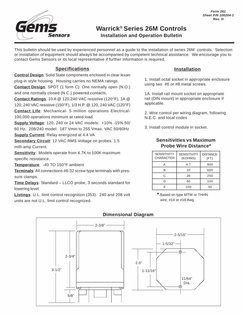
SpecificationsControl Design: Solid State components enclosed in clear lexan
plug-in style housing. Housing carries no NEMA ratings.
Contact Design: SPDT (1 form C): One normally open (N.O.)
and one normally closed (N.C.) powered contacts.
Contact Ratings: 10 A @ 120,240 VAC resistive (120°F), 1A @
120, 240 VAC resistive (150°F), 1/3 H.P. @ 120, 240 VAC (120°F)
Contact Life: Mechanical- 5 million operations Electrical-
100,000 operations minimum at rated load.
Supply Voltage: 120, 240 or 24 VAC models: +10% -15% 50/
60 Hz. 208/240 model: 187 Vmin to 255 Vmax. VAC 50/60Hz
Supply Current: Relay energized at 4.4 VA
Secondary Circuit: 12 VAC RMS Voltage on probes. 1.5
milli-amp Current.
Sensitivity: Models operate from 4.7K to 100K maximum
specific resistance.
Temperature: -40 TO 150°F ambient
Terminals: All connections #6-32 screw type terminals with pres-
sure clamps.
Time Delays: Standard – LLCO probe, 3 seconds standard for
lowering level.
Listings: U.L. limit control recognition (353). 240 and 208 volt
units are not U.L. limit control recognized.
Installation
1. Install octal socket in appropriate enclosureusing two #6 or #8 metal screws.
1A. Install rail mount socket on appropriaterail (DIN mount) in appropriate enclosure ifapplicable.
2. Wire control per wiring diagram, followingN.E.C. and local codes
3. Install control module in socket.
This bulletin should be used by experienced personnel as a guide to the installation of series 26M controls. Selectionor installation of equipment should always be accompanied by competent technical assistance. We encourage you tocontact Gems Sensors or its local representative if further information is required.
Dimensional Diagram
2-3/8”
3-1/2”
5/8”
2-3/4”
11/64”Dia.
2.0”
1-11/16”
1-5/32”
2-5/16”
Warrick® Series 26M ControlsInstallation and Operation Bulletin
Form 261Sheet P/N 100204-1
Rev. H
* Based on type MTW or THHN wire, #14 or #16 Awg
Sensitivities vs MaximumProbe Wire Distance*
SENSITIVITYCHARACTER
SENSITIVITY(KOHMS)
DISTANCE(FT)
A
B
C
D
E
4.7
10
26
50
100
900
600
250
100
50

Options:Automatic Reset: (Reset terminals notused): When the liquid rises to the electrodeon terminal 6, the control energizes, chang-ing state of the load contacts. (LED will belit) The control remains energized until theliquid level recedes below electrode on ter-minal 6. The control then de-energizes, (LEDwill not be lit) returning load contacts to origi-nal state. Unless otherwise specified, thereis a three second time delay on decreasinglevel. Liquid must be below probe on termi-nal 6 for a full three seconds before controlde-energizes.Manual Reset : (Normal ly closedpushbutton installed across terminals #7and #8): When the liquid rises to the elec-trode on terminal 6, the control will remainde-energized until the pushbutton is de-pressed. The control will then energize, (LEDwill be lit) changing the state of the con-tacts. The control remains energized until
the liquid level recedes below electrode on terminal 6. The control then de-energizes, (LED will not be lit) returning loadcontacts to their original state. Unless otherwise specified, there is a three second time delay on decreasing level. Liquidmust be below probe on terminal 6 for full three seconds before control de-energizes.Manual Reset with Optional Power Outage Feature: (Normally closed pushbutton across reset terminals) Con-trol will ignore power loss to control. With liquid above electrode on terminal 6, a power outage will cause the control tode-energize, but will automatically energize upon return of power. However, loss of liquid will cause control to de-ener-gize and remain so until liquid again rises to electrode and pushbutton is depressed.Dirty Electrode Detection: The LED will flash every half-second once the probe resistance reaches a value greaterthan the nominal control sensitivity rating. The relay state will not change until it exceeds the nominal sensitivity by morethan 25% (typically) at nominal input voltage. At which time the LED and relay contact return to the dry state. Such acondition may suggest electrode maintance is required.Test Feature Allows LLCO circuit to be tested. Holding down the reset button for 3 seconds will allow the LLCO circuitto trip which simulates the loss of water, without the need of draining the water level in the boiler. The control will return tonormal operation once the reset button is pressed a second time.
Wiring Diagram
IF METALLIC, TANK MAY BE USEDINSTEAD OF REFERENCE PROBE
Low Level Cut-0ff Probe
Reference Probe
Reset
AC Power
G LWCO
NO
L1 NC
L2
8
9
6
1
7
3
1011
54
2
Gems Sensors Inc.One Cowles RoadPlainville, CT 06062-1198Tel: 860-793-4579Fax: 860-793-4580
26M X X X X X XX XX X
Dirty Probe: Blank = No Dirty Probe, A = With Dirty Probe
Time Delay Increasing Level: 00-90 seconds. Blank = 0 seconds
Time Delay Decreasing Level: 03-90 seconds. Blank = 3 seconds
Optional Character: Optional character chart
Enclosure: 0=None, 1=NEMA 1, 4=NEMA 4
Socket Style: A=11 Pin Octal, B=DIN mount, M=None,module only
Supply Voltage: 1=120VAC, 2=240VAC, 3=24VAC, 8=208/240VAC
Sensitivity : A=4.7K, B=10K, C=26K, D=50K, E=100K
Optional Character Chart
N.C.Pushbutton
A
B
C
E
F
Y
Z
X
X
X
X
X
PowerOutage
X
X
X
X
TestFeature
X
X
X
XNo Option