model name description cfps-102
TRANSCRIPT

CFPS-10y
Model Name Description
CFPS-102 A 1.8V version
CFPS-103 A 2.5V version
CFPS-104 A 3.3V version
32.768kHz output crystal oscillator in a ceramic package, hermetically sealed with a seam sealed metal
lid
Suitable for real time clock applications
IQD Frequency Products Ltd ■ Station Road ■ Crewkerne ■ Somerset ■ TA18 8AR ■ United Kingdom
Tel: +44 (0)1460 270200 ■ Fax: +44 (0)1460 72578 ■ Email: [email protected]
Registered in England No: 06478545 ■ VAT Registration No: GB932 4502 45
CFPS-10y

CFPS-102Crystal Clock Oscillator Specification
ISSUE 5; January 2022
Outline (mm)
Recommended Solder Pad Layout
Description
32.768kHz output crystal oscillator in a ceramic package,
hermetically sealed with a seam sealed metal lid. Suitable for
real time clock applications.
Frequency Parameters
Frequency 32.768kHz
Frequency Stability ±20.00ppm to ±50.00ppm
±3ppm max per yearAgeing
Electrical Parameters
1.8V ±5%Supply Voltage
Operating Temperature Ranges
-20 to 70°C
-10 to 70°C
-40 to 85°C
Output Details
Output Compatibility CMOS
Drive Capability 15pF max
Output Control
Standby Operation:
Logic ‘1’ (>70% VS) to pad 1 enables oscillator output
Logic ‘0’ (<30% VS) to pad 1 disables oscillator output; when
disabled the oscillator output goes to the high impedance state
No connection to pad 1 enables oscillator output.
Start-up Time: 35ms max
2ms typ to 90% of final amplitude (under ideal conditions @
25°C)
Standby Current: 20µA max, 1.7µA typ @ 25°C
Environmental Parameters
Storage Temperature Range: –55 to 125°C
Shock: MIL-STD-883F, Method 2002.4: 1500G, 0.5ms, 3
times in each of 3 mutually perpendicular planes
Vibration: MIL-STD-883F, Method 2007.3: 20G
(20Hz-2000Hz), 1.52mm amplitude, 20mins in 3 mutually
perpendicular planes (total 4hrs)
Ordering Information
Frequency*
Model*
Output
Frequency Stability*
Operating Temperature Range*
Supply Voltage
(*minimum required)
Example
32.768kHz CFPS-102
CMOS ±50ppm –10 to 70C 1.8V
Compliance
CompliantRoHS Status (2015/863/EU)
CompliantREACh Status
MSL Rating (JDEC-STD-033): Not Applicable

CFPS-102Crystal Clock Oscillator Specification
ISSUE 5; January 2022
Packaging Details
Tape & reel in accordance with EIA-481-DPack Style: RL3K
Pack Size: 3,000
In tape, cut from a reelPack Style: Cutt
Pack Size: 100
Tape & reel in accordance with EIA-481-DPack Style: Reel
Pack Size: 1,000
Test Circuit Wave Form
Electrical Specification - maximum limiting values 1.80V ±5%
Frequency
Min
Temperature Range Stability
(Min)
Current
Draw
Rise and Fall
Time
Duty Cycle
°C ppm mA ns %
1.5 50-40 to 85 32.768kHz ±25.00 40/60%
1.5 50-20 to 70 ±20.00 40/60%
1.5 50-10 to 70 ±20.00 40/60%
This document was correct at the time of printing; please contact your local sales office for the latest version.
Click to view latest version on our website.

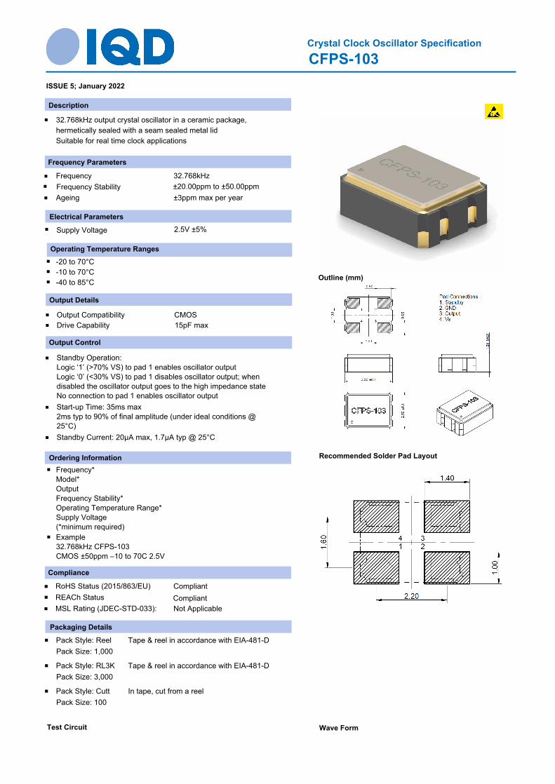
CFPS-103Crystal Clock Oscillator Specification
ISSUE 5; January 2022
Outline (mm)
Recommended Solder Pad Layout
Description
32.768kHz output crystal oscillator in a ceramic package,
hermetically sealed with a seam sealed metal lid
Suitable for real time clock applications
Frequency Parameters
Frequency 32.768kHz
Frequency Stability ±20.00ppm to ±50.00ppm
±3ppm max per yearAgeing
Electrical Parameters
2.5V ±5%Supply Voltage
Operating Temperature Ranges
-20 to 70°C
-10 to 70°C
-40 to 85°C
Output Details
Output Compatibility CMOS
Drive Capability 15pF max
Output Control
Standby Operation:
Logic ‘1’ (>70% VS) to pad 1 enables oscillator output
Logic ‘0’ (<30% VS) to pad 1 disables oscillator output; when
disabled the oscillator output goes to the high impedance state
No connection to pad 1 enables oscillator output
Start-up Time: 35ms max
2ms typ to 90% of final amplitude (under ideal conditions @
25°C)
Standby Current: 20µA max, 1.7µA typ @ 25°C
Environmental Parameters
Storage Temperature Range: –55 to 125°C
Shock: MIL-STD-883F, Method 2002.4: 1500G, 0.5ms, 3
times in each of 3 mutually perpendicular planes
Vibration: MIL-STD-883F, Method 2007.3: 20G
(20Hz-2000Hz), 1.52mm amplitude, 20mins in 3 mutually
perpendicular planes (total 4hrs)
Ordering Information
Frequency*
Model*
Output
Frequency Stability*
Operating Temperature Range*
Supply Voltage
(*minimum required)
Example
32.768kHz CFPS-103
CMOS ±50ppm –10 to 70C 2.5V
Compliance
CompliantRoHS Status (2015/863/EU)
CompliantREACh Status
MSL Rating (JDEC-STD-033): Not Applicable

CFPS-103Crystal Clock Oscillator Specification
ISSUE 5; January 2022
Packaging Details
Tape & reel in accordance with EIA-481-DPack Style: Reel
Pack Size: 1,000
Tape & reel in accordance with EIA-481-DPack Style: RL3K
Pack Size: 3,000
In tape, cut from a reelPack Style: Cutt
Pack Size: 100
Test Circuit Wave Form
Electrical Specification - maximum limiting values 2.50V ±5%
Frequency
Min
Temperature Range Stability
(Min)
Current
Draw
Rise and Fall
Time
Duty Cycle
°C ppm mA ns %
2.5 50-40 to 85 32.768kHz ±25.00 40/60%
2.5 50-20 to 70 ±20.00 40/60%
2.5 50-10 to 70 ±20.00 40/60%
This document was correct at the time of printing; please contact your local sales office for the latest version.
Click to view latest version on our website.

CFPS-104Crystal Clock Oscillator Specification
ISSUE 5; January 2022
Outline (mm)
Recommended Solder Pad Layout
Description
32.768kHz output crystal oscillator in a ceramic package,
hermetically sealed with a seam sealed metal lid
Suitable for real time clock applications
Frequency Parameters
Frequency 32.768kHz
Frequency Stability ±20.00ppm to ±50.00ppm
±3ppm max per yearAgeing
Electrical Parameters
3.3V ±5%Supply Voltage
Operating Temperature Ranges
-20 to 70°C
-10 to 70°C
-40 to 85°C
Output Details
Output Compatibility CMOS
Drive Capability 15pF max
Output Control
Standby Operation:
Logic ‘1’ (>70% VS) to pad 1 enables oscillator output
Logic ‘0’ (<30% VS) to pad 1 disables oscillator output; when
disabled the oscillator output goes to the high impedance state
No connection to pad 1 enables oscillator output
Start-up Time: 35ms max
2ms typ to 90% of final amplitude (under ideal conditions @
25°C)
Standby Current: 20µA max, 1.7µA typ @ 25°C
Environmental Parameters
Storage Temperature Range: –55 to 125°C
Shock: MIL-STD-883F, Method 2002.4: 1500G, 0.5ms, 3
times in each of 3 mutually perpendicular planes
Vibration: MIL-STD-883F, Method 2007.3: 20G
(20Hz-2000Hz), 1.52mm amplitude, 20mins in 3 mutually
perpendicular planes (total 4hrs)
Ordering Information
Frequency*
Model*
Output
Frequency Stability*
Operating Temperature Range*
Supply Voltage
(*minimum required)
Example
32.768kHz CFPS-104
CMOS ±50ppm –10 to 70C 3.3V
Compliance
CompliantRoHS Status (2015/863/EU)
CompliantREACh Status
MSL Rating (JDEC-STD-033): Not Applicable

CFPS-104Crystal Clock Oscillator Specification
ISSUE 5; January 2022
Packaging Details
Tape & reel in accordance with EIA-481-DPack Style: Reel
Pack Size: 1,000
In tape, cut from a reelPack Style: Cutt
Pack Size: 100
Tape & reel in accordance with EIA-481-DPack Style: RL3K
Pack Size: 3,000
Test Circuit Wave Form
Electrical Specification - maximum limiting values 3.30V ±5%
Frequency
Min
Temperature Range Stability
(Min)
Current
Draw
Rise and Fall
Time
Duty Cycle
°C ppm mA ns %
3.5 50-40 to 85 32.768kHz ±25.00 40/60%
3.5 50-20 to 70 ±20.00 40/60%
3.5 50-10 to 70 ±20.00 40/60%
This document was correct at the time of printing; please contact your local sales office for the latest version.
Click to view latest version on our website.

CFPS-102Crystal Clock Oscillator Specification
ISSUE 5; January 2022
Outline (mm)
Recommended Solder Pad Layout
Description
32.768kHz output crystal oscillator in a ceramic package,
hermetically sealed with a seam sealed metal lid. Suitable for
real time clock applications.
Frequency Parameters
Frequency 32.768kHz
Frequency Stability ±20.00ppm to ±50.00ppm
±3ppm max per yearAgeing
Electrical Parameters
1.8V ±5%Supply Voltage
Operating Temperature Ranges
-20 to 70°C
-10 to 70°C
-40 to 85°C
Output Details
Output Compatibility CMOS
Drive Capability 15pF max
Output Control
Standby Operation:
Logic ‘1’ (>70% VS) to pad 1 enables oscillator output
Logic ‘0’ (<30% VS) to pad 1 disables oscillator output; when
disabled the oscillator output goes to the high impedance state
No connection to pad 1 enables oscillator output.
Start-up Time: 35ms max
2ms typ to 90% of final amplitude (under ideal conditions @
25°C)
Standby Current: 20µA max, 1.7µA typ @ 25°C
Environmental Parameters
Storage Temperature Range: –55 to 125°C
Shock: MIL-STD-883F, Method 2002.4: 1500G, 0.5ms, 3
times in each of 3 mutually perpendicular planes
Vibration: MIL-STD-883F, Method 2007.3: 20G
(20Hz-2000Hz), 1.52mm amplitude, 20mins in 3 mutually
perpendicular planes (total 4hrs)
Ordering Information
Frequency*
Model*
Output
Frequency Stability*
Operating Temperature Range*
Supply Voltage
(*minimum required)
Example
32.768kHz CFPS-102
CMOS ±50ppm –10 to 70C 1.8V
Compliance
CompliantRoHS Status (2015/863/EU)
CompliantREACh Status
MSL Rating (JDEC-STD-033): Not Applicable

CFPS-102Crystal Clock Oscillator Specification
ISSUE 5; January 2022
Packaging Details
Tape & reel in accordance with EIA-481-DPack Style: RL3K
Pack Size: 3,000
In tape, cut from a reelPack Style: Cutt
Pack Size: 100
Tape & reel in accordance with EIA-481-DPack Style: Reel
Pack Size: 1,000
Test Circuit Wave Form
Electrical Specification - maximum limiting values 1.80V ±5%
Frequency
Min
Temperature Range Stability
(Min)
Current
Draw
Rise and Fall
Time
Duty Cycle
°C ppm mA ns %
1.5 50-40 to 85 32.768kHz ±25.00 40/60%
1.5 50-20 to 70 ±20.00 40/60%
1.5 50-10 to 70 ±20.00 40/60%
This document was correct at the time of printing; please contact your local sales office for the latest version.
Click to view latest version on our website.
CFPS-103Crystal Clock Oscillator Specification
ISSUE 5; January 2022
Outline (mm)
Recommended Solder Pad Layout
Description
32.768kHz output crystal oscillator in a ceramic package,
hermetically sealed with a seam sealed metal lid
Suitable for real time clock applications
Frequency Parameters
Frequency 32.768kHz
Frequency Stability ±20.00ppm to ±50.00ppm
±3ppm max per yearAgeing
Electrical Parameters
2.5V ±5%Supply Voltage
Operating Temperature Ranges
-20 to 70°C
-10 to 70°C
-40 to 85°C
Output Details
Output Compatibility CMOS
Drive Capability 15pF max
Output Control
Standby Operation:
Logic ‘1’ (>70% VS) to pad 1 enables oscillator output
Logic ‘0’ (<30% VS) to pad 1 disables oscillator output; when
disabled the oscillator output goes to the high impedance state
No connection to pad 1 enables oscillator output
Start-up Time: 35ms max
2ms typ to 90% of final amplitude (under ideal conditions @
25°C)
Standby Current: 20µA max, 1.7µA typ @ 25°C
Ordering Information
Frequency*
Model*
Output
Frequency Stability*
Operating Temperature Range*
Supply Voltage
(*minimum required)
Example
32.768kHz CFPS-103
CMOS ±50ppm –10 to 70C 2.5V
Compliance
CompliantRoHS Status (2015/863/EU)
CompliantREACh Status
MSL Rating (JDEC-STD-033): Not Applicable
Packaging Details
Tape & reel in accordance with EIA-481-DPack Style: Reel
Pack Size: 1,000
Tape & reel in accordance with EIA-481-DPack Style: RL3K
Pack Size: 3,000
In tape, cut from a reelPack Style: Cutt
Pack Size: 100
Test Circuit Wave Form

CFPS-103Crystal Clock Oscillator Specification
ISSUE 5; January 2022
Electrical Specification - maximum limiting values 2.50V ±5%
Frequency
Min
Temperature Range Stability
(Min)
Current
Draw
Rise and Fall
Time
Duty Cycle
°C ppm mA ns %
2.5 50-40 to 85 32.768kHz ±25.00 40/60%
2.5 50-20 to 70 ±20.00 40/60%
2.5 50-10 to 70 ±20.00 40/60%
This document was correct at the time of printing; please contact your local sales office for the latest version.
Click to view latest version on our website.
Printed on 20 Jan 22 12:08 using Model Data Sheet V1.2647 Page 11 of 11
Sales Office Contact Details:
USA: +1.760.318.2824
France: 0800 901 383UK: +44 (0)1460 270200
Germany: 0800 1808 443
Email: [email protected]
Web: www.iqdfrequencyproducts.com